1
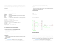
Version 2.1
CONTENT
www.PhillipsBurle.com
Replacement Turnstiles for Phillips Burle
PASSAGE USER MANUAL
TPW-321ASP
1. Preface ................................................................................. 3
2. Description of product:.......................................................... 4
2.1. Function:..................................................................... 4
2.2. Technical Specification ............................................... 5
2.3. Standard Accessories and Optional Extras................. 5
3. Structure ............................................................................... 6
3.1. Size of equipment....................................................... 6
3.2. Working Principle ....................................................... 6
3.3. Working Mode ............................................................ 7
3.4. System Integration ..................................................... 7
4. Installation ............................................................................ 8
4.1. Casework Installation ................................................. 8
4.2. Electric Installation ..................................................... 8
5. Debugging ............................................................................ 9
6. Maintenance ....................................................................... 10
Installation Diagram (Figure 1): .............................................. 12
Main Board Diagram (Figure 2): ............................................. 12
www.TURNSTILES.us * 8641 South Warhawk Rd., Conifer, Colorado 80433
Office: 303 569 6776 ext 101 * Fax: 303 679 8949 email: [email protected]
costs if the warranty period has expired. The commitment will terminate automatically if the users have
performed the following acts to the products:
1. Preface
1) Alterations, demolition and other operations by the users themselves that can not guarantee the
integrity of the product.
2) Users are not in accordance with the contents of this manual to use the products properly and lead to
Dear Customers:
damage in whole or in part.
Thank you for choosing www.TURNSTILES.us Access Control products. Our TPW Series Turnstiles
adopt the unique technologies of our company --- to lock and unlock automatically, making the turnstile
Warning:
locked accurately and reliably at zero position. The passage is convenient and safe. The equipment is
1) As the products are of high technology, if there’s any malfunction occurring to the system, please
available with standard electrical interface so as to integrate easily with various read & write device such
inform our company after-sales service department or any authorized service agents timely to handle.
as magnetic card, barcode card, ID card, and IC card, etc. The products have been designed to be
Please do not dismantle the equipment arbitrarily so as to avoid damaging the internal structure or any
available with many types of models and specifications. It can widely apply to high grade sites such as
harm to you due to improper operation.
governments, enterprises, offices which are in need of intelligent public passage management.
2) It is forbidden to sit or lean on the gate of the equipment so as to avoid any unnecessary damage to
The fully automatic passage turnstile is developed and manufactured strictly in accordance with related
the equipment.
standards of mechanical and electrical products. The products have been tested strictly and carefully.
3) The product is with the dangerous power voltage during operation. Please check the system
The equipment is of high technology. To ensure that it can work safely and reliably and to ensure the
protection ground periodically to as to avoid unnecessary harm to the users.
safety of the users, the items needed to be paid attention to has been specified specially in this manual.
4) Please refer to the manual to use the electrical interface properly so as to avoid any damage to the
Please read this manual carefully before using the equipment so as to avoid any harm to you due to
equipment or other device.
improper operation.
5) The equipment is not available with the explosion-proof design, so please do not use the equipment
Announcement:
in the explosive environment. Please select other suitable models of our company if needed.
The products are CE approved. All technologies such as product appearance, control, driving shall
belong to the www.TURNSTILES.us.
2. Description of product:
www.TURNSTILES.us reserves the rights to improve or perfect the products, so we cannot ensure that
the products you purchase will be exactly conforming to the manual. Anyway, we will check and edit the
manual periodically. The company reserves the right to make any amendments to this manual without
2.1. Function:
notice.
Customer service and technical support commitment:
TPW-321ASP is a fully automatic turnstile. Its unique drive design allows the swing to be open
Starting from the day that the customers purchase the unit, www.TURNSTILES.us will provide one-year
automatically without hand-push and to be reposition automatically. It can effectively control high
warranty, technical support and maintenance. www.TURNSTILES.us will only charge maintenance
www.TURNSTILES.us * 8641 South Warhawk Rd., Conifer, Colorado 80433
Office: 303 569 6776 ext 101 * Fax: 303 679 8949 email: [email protected]
www.TURNSTILES.us * 8641 South Warhawk Rd., Conifer, Colorado 80433
Office: 303 569 6776 ext 101 * Fax: 303 679 8949 email: [email protected]
volume human traffic (maximum up to 40 persons per minute) whole still maintaining a welcoming
atmosphere. They can easily be integrated with any electronic system for ticketing, access control or
- LCD counters to count people entering or exiting the (inside or outside)
● Drop Arm
-In the event of an emergency or isolation of the power supply the horizontal tripod arm will drop
time attendance.
automatically to create a clear walkway for escape.
2.2. Technical Specification
Drive:
Fully automatic (Brushless Motor)
Orientation:
Bi-directional
Materials:
Casework: 304 Grade Stainless Steel; Swing: Lexan Panels (Color: transparent)
Finish:
Brushed surface
● Ticket system integration
3. Structure
3.1. Size of equipment
Shell’ size:
47 ¼” (1200mm) H x 6 ½” (168) mm Diameter x 13 ¾” (350mm) Swing (Standard)
Transit speed:
30-40 persons per minute
Drive Interface:
Dry contact signal or +12V electrical level signal
Communication Interface: RS485 (≤1200mm)
Power Supply:
220V AC 50Hz (110V AC 60HZ) Max Power Rating: 50VA
Logic Voltage:
24V DC
Working Temperature: -4 F / 20 ℃ to +140 F / 60 ℃
2.3. Standard Accessories and Optional Extras
● Card reader Mounting (Please refer to TURNSTILES RFID for feasibility)
- Surface mounting only of customer supplied readers
- Card reader Pedestals
● Traffic-lights
3.2. Working Principle
- LED traffic-lights are available to give availability to transit in a specific direction.
● Remote Control
- C-TR20 Control Module: to set turnstile operation modes (free, locked or controlled by card reader)
- Single entry push-button
● Counters
www.TURNSTILES.us * 8641 South Warhawk Rd., Conifer, Colorado 80433
Office: 303 569 6776 ext 101 * Fax: 303 679 8949 email: [email protected]
The equipment consists of stainless steel shell, core, main controller, read & write device, etc.
Customers can select to mount the read & write device either supplied by our company
( www.EntraPASS.com ) , or by other suppliers according their needs. As different read & write device &
display device are to mount on different models, the position and way of mounting will differ. So the
www.TURNSTILES.us * 8641 South Warhawk Rd., Conifer, Colorado 80433
Office: 303 569 6776 ext 101 * Fax: 303 679 8949 email: [email protected]
customers just need to inform us of the mounting way & dimensions in advance if they choose to mount
their own read & write device. When the reader reads the card swiped by a user, the valid card or switch
4. Installation
will give an open signal to the main controller. The main controller will control the motor to drive the
coupled dual-cam to turn a certain angle to unlock the gate. Then the swing gate will turn 90 degrees
automatically. After the user passes through the gate, it will reset and lock automatically. When a user
4.1. Casework Installation
does not pass through the gate with the preset time, the gate will reset and lock automatically. The time
limit can be set on the main board
Step1: Check out the accessories according to packing list.
Step2: Open the cover of card reader at the top of turnstile, install client’s needed reader, at the same
3.3. Working Mode
time, extend the reader’s signal to the wire hole of turnstile, and then fix the top cover.
Step3: Open controlling door of equipment body with key, leading out the power supply and signal wire
The equipment is available with the following working modes so that the users can select according to
different situations conveniently:
1) Double direction card reading, double direction passage (Default)
2) Single direction passage by card reading, passage of the other direction forbidden
3) Single direction passage by card reading, passage of the other direction free
from wire of bottom according to the wiring diagram of main board (refer to figure2), and then lock the
controlling door.
Step4: At the position of threaded hole, thread the cable wire with 3/4”PVC conduit tube, and then bury
the cable wire to the appropriate location by cement.
Step5: According to the installation requirements of figure1 and bolt hole and threaded hole position of
base frame, confirm whether the installation position of each turnstile is correct or not, and then rebury
four M12 stone bolts at the installation position or four M12 plug bolts, after installation turnstile, fix the screw.
3.4. System Integration
Warning:
The equipment can be used separately to form a single intelligent management passage. It can also be
integrated with many other units to form more than one intelligent management passages. Meanwhile, it
can be connected with the control PC to feed back the passage and equipment status to the
administrator so as to generate various management reports. Moreover, the administrator can realize
the long distance control on the equipment via the management of PC.
1)All above operations should be operated under the power-off situation, and make sure the protective
grounding wires of system well and correctly connect.
2)When the chosen equipment is used for outdoors, build 100mm~200mm high cement mounting
platform at the equipment installation position for damp insulation; at the same time, add sun shed such kind
of sheltering facilities at the top of equipment. It is prohibited that install the turnstile to use in the open air.
4.2. Electric Installation
Step1: According to system wiring diagram, carefully check the system wiring situation, especially after
confirm the signal and plus-minus wiring of power supply are correct, the power is on.
www.TURNSTILES.us * 8641 South Warhawk Rd., Conifer, Colorado 80433
Office: 303 569 6776 ext 101 * Fax: 303 679 8949 email: [email protected]
www.TURNSTILES.us * 8641 South Warhawk Rd., Conifer, Colorado 80433
Office: 303 569 6776 ext 101 * Fax: 303 679 8949 email: [email protected]
Step2: According to the registered effective card or use switch button, check the swing’s turning angle
needed:
and direction.
a.Device number setting: according to the described methods of Appendix Main Board Diagram
(Figure 2), by P07 menu, set the turnstile address as the needed address.
b. By the management software of upper computer to open turnstile, the turnstile should reliably
5. Debugging
perform the related actions, otherwise, please carefully check the communication line, the plugging
position of communication link.
Equipment function test
Function tests as follows: (according to user’s different requirements to turnstile function, do the function
6. Maintenance
test as following items or full items)
1) Card-swiping access by single time
Swiping card at entry direction or exit direction, for legal card, electrical motor will automatically unlock
This turnstile shell is made of Matte stainless steel; please often scrub the appearance by soft textile to
by coupling double cam mechanism, and the swing will automatically open. At the same time, it will wait
keep tidy and clean. Please do not scrub the appearance by hard materials to avoid scuffing to effect elegance.
for people’s entering, when the swing turns at a certain angle to stop, and then it will automatically reset
At the same time, do not wash by water so as not to cause short circuit of electric control system to damage
and dead locked within the setting time.
the turnstile.
2)Card-swiping access by multi- times
Regularly check the connection situation of each moving position of the turnstile. If you find there is
Card-swiping access by multi-times at entry or exit direction, after one people passes, the turnstile will
loosening nut and bolt such kind of fastening pieces, please screw down in time to avoid the turnstile
automatically reset and lock. During testing for this function, the P08 function setting of the turnstile will
breakdown caused by long time moving.
be 0, otherwise, this function will be in vain.
Regularly check the connection situation of system protective ground to ensure its reliable grounding.
3)Card-swiping at one side, and freely access at the other side
Regularly check the socket connector and term-point connecting with circuit to ensure the reliable
Test for card-reading end, follow up 1) or 2) as above; for the freely access direction, slightly push the
connection.
turnstile arm along the access direction, the turnstile arm will turn along with passer. When the turnstile
arm turns at a certain angle, it will automatically return to zero position.
System menu setting description
4)Reposition function
A.1 System menu setting button
Swiping card at entry direction or exit direction, for legal card, electrical motor will automatically unlock
SET key: The function key for entry and exit from system function setting
by coupling double cam mechanism to wait for people’s entering. Within the regulated access time (set
INC key: The key to add one to the needed setting parameter
by users, the default time is 5 seconds), if there is nobody to pass, the turnstile will automatically reset,
DEC key: The key to decrease one to the needed setting parameter
and cancel this access permission without counting.
7)Press SET key to withdraw from menu setting, and switch to procedure running state.
7)Remotely control
A.2 The basic ways for entering and exiting from system function setting
When remotely control for the turnstile by managing computer, the following settings and tests are
1. The way to entering function setting
www.TURNSTILES.us * 8641 South Warhawk Rd., Conifer, Colorado 80433
Office: 303 569 6776 ext 101 * Fax: 303 679 8949 email: [email protected]
www.TURNSTILES.us * 8641 South Warhawk Rd., Conifer, Colorado 80433
Office: 303 569 6776 ext 101 * Fax: 303 679 8949 email: [email protected]
1)Under the system running state (the LED on the main controlling board of turnstile shows RUN),
press SET setting key to log-in the system function setting state, at this time, the LED shows “P00”,
Installation Diagram (Figure 1):
which means the system has been at the state of function setting.
2) Press INC key to make the system function number to be the needed function number (press INC
key each time, the system function number will be added one)
3) Press SET key to enter the state of this function parameter setting.
4) Press INC or DEC key to set parameter (INC makes the parameter number add one, DEC makes
the parameter number decrease one)
5) Press SET key to save setting value, and return to the menu function setting mode
2. Exit from the system function setting state
1)Press DEC key to make the system return to P00
2)Press SET key to exit from the menu setting, shifting to procedure running state, showing “RUN”.
3. System parameter
Each function parameter of controlling board and the implication description:
P00:The function number to enter the menu;
P01:Set the started speed of electrical motor; the value is larger, the started force moment of electrical motor is
larger, and the shock will be stronger; this suggested value is 450; this value range: 50-999
P02:Set the buffing speed after electrical motor reaches limit switch position; the value range is 50-999
P03:Set the speed-down running time for electrical motor; the unit is : mS;this value range is: 1-255;
P04:Set the high speed running time for electrical motor; this value range is : 50-999; the suggested setting
is 999;
P05:Set the smoothness when electrical motor speeds up; this suggested value is 80; this value range is
1-255;
!
Note:
All the above operations should be carried out by the qualified personnel by strictly training,
Main Board Diagram (Figure 2):
without permission, the user is prohibited to operate.
www.TURNSTILES.us * 8641 South Warhawk Rd., Conifer, Colorado 80433
Office: 303 569 6776 ext 101 * Fax: 303 679 8949 email: [email protected]
www.TURNSTILES.us * 8641 South Warhawk Rd., Conifer, Colorado 80433
Office: 303 569 6776 ext 101 * Fax: 303 679 8949 email: [email protected]
www.TURNSTILES.us
Turnstiles for Access Control
www.EntraPASS.com
Card Access Software & Hardware
www.TurnstileInstallation.com
Turnstiles Installed by qualified Engineers
www.PhillipsBurle.com
Replacement Turnstiles for Phillips Burle
www.TurnstileParts.com
Replacement Parts for most Manufacturers
www.Biometric-CCTV.com
Closed Circuit Video Recording
www.GSAGovernmentSupplier.com
Power, Racks, Surge Suppressors, Thermal and Wire Management
www.UsedTurnstiles.com
Sell the units you are replacing
www.AVLELEC.com
Soundmasking for Speech Privacy
Main Engineering Contact:
Patrick McAllister
303 670 1099
www.TURNSTILES.us * 8641 South Warhawk Rd., Conifer, Colorado 80433
Office: 303 569 6776 ext 101 * Fax: 303 679 8949 email: [email protected]
www.TURNSTILES.us * 8641 South Warhawk Rd., Conifer, Colorado 80433
Office: 303 569 6776 ext 101 * Fax: 303 679 8949 email: [email protected]