1
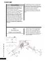
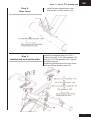
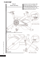
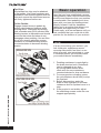
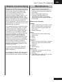
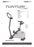
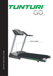
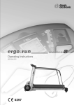
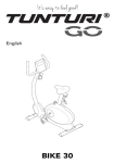
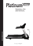
www.tunturi.com
SPRINTER BIKE PRO
USER MANUAL
Contents
Welcome ............................................. 2
Safety instructions ............................. 2
Assembly ............................................ 4
Step 1 ................................................. 4
Step 2 ................................................... 5
Step 3 ................................................... 5
Step 4 ................................................... 6
Welcome to the world of Tunturi
exercising!
Your choice shows that you really
want to invest in your well being and
condition; it also shows you really value
high quality, safe and motivating product
as your training partner. Whatever your
goal in training, we are certain this is
the training equipment to get you there.
You’ll find information about using your
exercise equipment and what makes for
efficient training at Tunturi’s website at
www.tunturi.com
Adjustments & setup.......................... 7
Adjustment of seat position .................. 7
Handlebar adjustment .......................... 7
How to use our dual function pedal ...... 7
Moving and storage............................ 8
Basic operation................................... 8
Basics on exercising .......................... 9
Maintenance ........................................ 9
Moving and storage ............................ 10
Troubleshooting .................................. 10
Owner ’s manual
•
P L AT I N U M P R O
Specifications ................................... 10
Spare parts list.....................................11
Exploded view .................................... 13
2
Safety Instructions
Read this guide through carefully
before assembling, using or servicing
your fitness equipment. Please keep
the guide somewhere safe; it will
provide you now and in the future with
the information you need to use and
maintain your equipment. Always follow
these instructions with care.
Note about your health
• Before you start any training, consult
a physician to check your state of
health.
• If you experience nausea, dizziness
or other abnormal symptoms while
exercising, stop your workout at once
and consult a physician.
• To avoid muscular pain and strain,
begin each workout by warming up
and end it by cooling down (slow
pedaling at low resistance). Don’t
forget to stretch at the end of the
workout.
Note about the exercise environment
• The equipment is not to be used
outdoors.
• Place the equipment on a firm,
level surface. Place the equipment
on a protective base to avoid any
damages to the floor beneath the
equipment.
Owner ’s manual
•
•
Make sure that the exercising
environment has adequate
ventilation. To avoid catching cold, do
not exercise in a draughty place.
In training, the equipment tolerates
an environment measuring +10°C to
+35°C. The equipment can be stored
in temperatures ranging between
-15°C and +40°C. Air humidity in the
training or storage environment must
never exceed 90%.
Note about the equipment
• If children are allowed to use
the equipment, they should be
supervised and taught to use the
equipment properly, keeping in
mind the child’s physical and mental
development and their personality.
• Before you start using the equipment,
make sure that it functions correctly
in every way. Do not use faulty
equipment.
• Press the keys with the tip of the
finger; your nails may damage the
key membrane.
• Never lean on the interface.
• Never remove the side covers. Do
not step on the frame casing.
• Only one person may use the
equipment at a time.
• Hold the handlebar for support when
getting on or off the equipment.
• Wear appropriate clothing and shoes
when exercising.
• Protect the meter from sunlight and
always dry the surface of the meter if
there are any drops of sweat on it.
• Further information on warranty
terms can be found in the warranty
booklet included with the product.
• Please note that the warranty does
not cover damage due to shipping
or negligence of adjustment or
maintenance instructions described
in this manual.
• The equipment must not be used by
persons weighing over 150 kg.
• Do not attempt any servicing or
adjustments other than those
described in this guide.
•
•
•
•
P L AT I N U M P R O
GB
Everything else must be left
to someone familiar with the
maintenance of electromechanical
equipment and authorized under
the laws of the country in question
to carry out maintenance and repair
work.
Never drop or insert any object into
any openings.
Do not use outdoors.
Do not use excessive pressure
on console control keys. They are
precision set to properly function with
little finger pressure. Pushing harder
is not going to make the unit go faster
or slower. If you feel the buttons are
not functioning properly with normal
pressure, contact your dealer.
SAVE THIS INSTRUCTION MANUAL
3
Assembly
Start by unpacking the equipment. The
detailed assembly instructions can be
found at the back of this guide. Follow
the instructions in given order.
Before assembly, check the contents of
the package. If a part is missing, please
contact your dealer with the model,
equipment serial no. And spare part no.
of the missing part. You’ll find a spare
part list at the back of this guide. The
hardware kit contents are marked with
* in the spare parts list. The directions
left, right, front and back are defined as
seen from the exercising position. Keep
the assembly tools, as you may need
them e.g. for adjusting the equipment.
Note that two people are needed for the
assembly.
Step 1:
Front and rear
support post Assembly
#81. 3/8”x3-1/2” Carriage bolt
4pcs.
#82. 3/8”
4pcs.
Cap nut
Owner ’s manual
•
P L AT I N U M P R O
#83. 3/8”x23x1.5 Curved washer 4pcs.
4
#85. 14 - 15mm
Wrench
1pcs.
The packaging includes a silicate bag for
absorbing moisture during storage and
transportation. Please dispose of the bag
once you have unpacked the equipment.
Allow at least 100 cm of clearance
around the equipment. We also
recommend opening the package and
assembling the product on a protective
base.
1. Install the front and rear support post
with four 3/8”×3-1/2” carriage bolts
(81), four 3/8” curved washers(83)
and four 3/8” cap nuts(82). The front
and rear support post are different.
Be sure to assemble the support post
with the transport wheels onto the
front of the bike.
Owner ’s manual
Step 2:
Rear cover
Step 3:
Handlebard and bottleholder
•
P L AT I N U M P R O
GB
1. Install the rear support post cover
with two M5 x 10mm screws (91).
Install the handlebar with four 5/16” x
15mm bolts (88), 5/16” split washers (49)
and four 5/16” flat washers (48). Tighten
the bolts securely.
Install the bottleholder to the main frame
with two Philips head screws (93).
5
Step 4:
Pedal assembly
Owner ’s manual
•
P L AT I N U M P R O
Right pedal
6
Left pedal
Install the Left (25L) and Right (25R)
pedal to the crank arm. Please note
that the Left pedal has a reverse
threaded bolt and needs to be tightened
in a counterclockwise direction. The
pedals are identified by either an R or L
stamped into the end of the bolt.
Owner ’s manual
Adjustments & setup
Take some time to learn how to properly
adjust the bike to your body; it will make
your workouts more pleasant and a
safer experience too. Riding the bike
when it is incorrectly adjusted can result
in discomfort and increase your risk of
injury.
Adjustment of seat possition
Seat height adjustment:
1. Standing next to the
bike, adjust seat until it
is about hip height.
2. Rotate crank arms until
the pedals are in the
vertical position
3. Place your foot in toe cage of pedal
closest to the floor and mount the
bike. Ensure that the ball of your foot
is over the center of pedal. Your leg
should be slightly bent at the knee,
about 5 degrees.
4. If your leg is too straight or your foot
cannot touch pedal you will need to
lower seat height. If your leg is bent
too much you will need to raise seat
height.
5. Dismount the bike. Loosen the quick
release lever on seat tube and adjust
up or down as necessary.
6. When seat is in the desired position,
tighten the quick release lever to
secure the seat tube.
7. Note the final position mark on the
seat tube for future reference.
Forward adjustments:
1. Sit on bike with crank
arms in the 3 and 9
o’clock positions.
For road bike training,
a proper forward/aft
position of the seat is
achieved when small bump at the top
of the shin is above pedal axle.
2. Dismount the bike. Loosen the quick
release lever under the seat and
slide the seat forward or backward
as desired; then tighten the quick
release lever.
•
P L AT I N U M P R O
GB
Handlebar adjustment
Handlebar Height Adjustment
1. The Handlebar height is
a matter of preference.
Start with a handlebar
height that is the same
as the seat’s height.
Adjusting the handlebar
higher will give the rider
a more upright position;
lower will result in a more crouched
position.
2. Raise or lower the handlebar by
loosening quick release lever on
handlebar tube and adjust by sliding
the handlebar mount up or down
as desired. Then tighten the quick
release lever to secure the handlebar
tube. Note the final position mark on
handlebar tube for future reference.
Adjustment of Handlebar’s Forward/
Aft Position:
1. Loosen the quick release lever
under the handlebar and slide the
handlebar forward or backward as
desired. Suitable forward/aft position
should allow the rider to comfortably
grasp the handlebar with a slight
bend at the elbow.
2. Tighten the quick release lever to
secure the handlebar.
How to use our dual
function pedal
Attaching Cleats to Your Shoes:
If you have questions it is recommended
that you consult a bicycle dealer for
assistance, or refer to your shoe
manufacturer’s instructions.
When fixing the cleat the lateral center
line should be under the center of the
ball of the foot. Adjust forward and
backward via the slots in the shoe sole.
Adjust laterally via play between cleat
washer and cleat. Tighten cleats very
firmly. Cleat position can be fine-tuned,
according to personal preference, after
trial use. It may take time to find your
optimum cleat set-up.
7
Toe Clips:
All standard toe clips can be attached
to the pedals. Use fixing hardware and
installation instructions supplied with toe
clips and ensure the attachment screws
are firmly tightened before use.
To Use Pedals:
Engage cleated shoes in pedals by
placing cleat between bindings while
pushing down. Disengage by twisting
heel outwards away from exercise bike.
Binding tension is adjustable and should
be set so that cleat and shoe do not
disengage when pedaling. Use an Allen
key to turn tension adjusting screws,
clockwise to increase binding tension,
counterclockwise to decrease binding
tension.
Basic operation
Now that you have established a proper
riding position, take a few minutes to ride
the bike and determine that your position
is comfortable. Start pedaling at a slow
pace with your toes and knees pointed
directly forward. Hold the handlebar
lightly and in a position that allows your
shoulders and upper body to relax.
Pedal easily, at a low resistance until you
feel confident that you could ride in that
position for the duration of your workout.
NOTE!
If at any time during your workout, you
feel chest pain, experience severe
muscular discomfort, feel faint, or are
short of breath, stop exercising at once.
If condition persist, you should consult
your medical doctor immediately
Owner ’s manual
•
P L AT I N U M P R O
1. Pedaling resistance is controlled by
the brake tension knob. Resistance
can be changed at any time
by turning brake tension knob:
clock-wise for more resistance;
counterclockwise for less resistance.
2. For emergencies or braking, press
the red resistance knob firmly to stop
the flywheel.
3. Before dismounting, apply the
brake to stop flywheel, or increase
resistance and let flywheel come to a
stop.
4. If the product is not stable, adjust
the stabilizing screws under the rear
support appropriately.
8
Owner ’s manual
Basics on exercising
Working out with this device is excellent
aerobic exercise, the principle being that
the exercise should be suitably light,
but of long duration. Aerobic exercise
is based on improving the body’s
maximum oxygen uptake, which in turn
improves endurance and fitness. The
ability of the body to burn fat as a fuel is
directly dependent on its oxygen-uptake
capacity. Aerobic exercise should be
above all pleasant. You should work up a
light sweat but you should not get out of
breath during the workout.
You should exercise at least three times
a week, 30 minutes at a time, to reach
a basic fitness level. Maintaining this
level requires a few exercise sessions
each week. Once the basic condition
has been reached, it is easily improved,
simply by increasing the number of
exercise sessions. You should start
slowly at a low pedaling speed and low
resistance, because for an overweight
person strenuous exercise may subject
the heart and circulatory system to
excessive strain. As fitness improves,
resistance and pedaling speed can be
increased gradually.
To set the exercising level, adjust the
tension knob on the handlebar for a
higher resistance.
For a higher resistance, turn the tension
knob clockwise, for a lower resistance
turn the tension knob counter-clockwise.
•
P L AT I N U M P R O
GB
Maintenance
•
•
Do not service internal parts of
pedals. If they are found to be worn
internally, we recommend replacing
the pedal.
Use of lubricants or cleaning
solutions other than those so
specified will result in diminished
performance and a shorter life span
for that part.
Maintenance Schedule
Pedals:
1. Ensure that pedals are tight in crank
arms; that all screws on pedals are
tight; and that the pedal straps are
not frayed.
2. Before each use.
Frame:
1. Wipe down by using a soft damp
clean cloth.
2. Daily.
3. Water.
Flywheel:
1. Wipe down by spraying on a rag and
applying a light coat to sides of the
flywheel.
2. Weekly.
3. WD-40 spray.
Brake pad:
1. Inspect for excessive wear or a dry
leather brake pad.
2. Weekly.
3. 3-IN-ONE Oil or 10W oil. Do not use
silicone-based lubricants.
9
moving and storage
Please follow these instructions when
carrying and moving the equipment,
because lifting it incorrectly may strain
your back or risk other accidents:
•
•
Standing in front of the device, tilt
the device slowly towards you, and
push from the front and push along
the floor on the wheels at the front
support. We recommend that you use
a protective base when transporting
the equipment.
To prevent the equipment
malfunctioning, store in a dry place
with as little temperature variation as
possible and protected from dust.
Specifications
Length...........................................107cm
Width .............................................54 cm
Height ..........................................103cm
Weight ...........................................68 kg
The Sprinter l meets the requirements
of the EU’s and therefore carries the CE
label.
The Sprinter meets EN precision and
safety standards (EN-957). Class S
and shall be used in a supervised
environment.
Due to our continuous policy of product
development, Tunturi reserves the right
to change specifications without notice.
Troubleshoot
Despite continuous quality control,
defects and malfunctions caused by
individual components may occur
in the equipment. In most cases it’s
unnecessary to take the whole device
in for repair, as it’s usually sufficient
to replace the defective part. Always
give the model, serial number of your
equipment and in case of malfunctions
also conditions of use, nature of
malfunction and any error code.
Owner ’s manual
•
P L AT I N U M P R O
When you encounter unusual behaviour
from the device, contact your local
Tunturi dealer for service.
10
If you require spare parts, always
give the model, serial number of your
equipment and the spare part number
for the part you need. The spare part list
is at the back of this manual. Use only
spare parts mentioned in the spare part
list.
NOTE!
The instructions must be followed
carefully in the assembly, use and
maintenance of your equipment.The
warranty does not cover damage due to
negligence of the assembly, adjustment
and maintenance instructions decribed
herein. Changes of modifications not
expressly approved by Tunturi Fitness
BV will void the user’s authority to
operate the equipment.
We wish you many enjoyable trainings!
Owner ’s manual
Spare parts list
Buble
1
2
3
4
5
6
7
8
9
10
11
12
14
15
16
18
19
20
21
22
23
25
26
27
29
30
31
32
33
34
35
36
37
38
Description
Main frame
Front support post
Rear support post
Handlebar post
Seat post
Handlebar
Sliding seat mount
Sliding handlebar mount
(front)
Braking pad holder
Brake pad - wool felt
Bushing
Nut
Spring (Ø13×Ø10×16L)
Nut (M10x3T)
Brake tension knob
Phillips head screw
(M6×15m/m)
Quick release lever
(8×40m/m)
Quick release lever
(8×25m/m)
Handlebar locking blocks
Flat washer (5/1”×35×3.0T)
Bottle holder
Pedal pair
Anti rotation washer
Seat
Tapping screw (5×16m/m)
Sheet metal screw
(3.5×12m/m)
Flywheel (& 32~38,66,68)
Bearing housing
Flywheel Axle
Woodruff key (5×18L)
Flywheel pulley (Ø66×22m/m)
Button head socket bolt
(5/16”×3/4”)
Flat washer (5/16”×20×3.0T)
Button head socket bolt
(5/16”×3/4”)
39
Qty
1
1
1
1
1
1
1
1
1
1
1
1
2
2
1
4
2
2
4
1
1
1
1
1
2
3
1
2
1
1
1
1
2
6
40
41
42
43
44
45
46
48
49
50
53
54
55
56
57
58
59
60
61
62
63
65
66
67
68
69
70
71
72
73
74
75
77
78
79
80
81
82
•
P L AT I N U M P R O
Phillips head screw
(M6×10m/m)
Belt
Flywheel pulley
(Ø209×21m/m)
Crank arm (L)
Crank arm (R)
Crank arm end cap (M22×1.0/
Ø23)
Crank axle
Button head socket bolt
(5/16”×1/2”)
Flat washer (5/16”×16×1T)
Split washer (5/16”×1.5T)
Transport wheel
Foot pad (& 54,72,79)
Nut 3/8”
Support post end cap
Lower tube sleeve
Upper seat tube sleeve
Bottom end cap, eye tube
Rear support post cover
Chain cover (RH)
Chain cover (LH)
Flywheel cover
Pulley cover
Bearing (6203)
Bearing (6004)
C Ring Ø17
C Ring
Hex head bolt (1/4”×3”)
Hex head bolt (1/4”)
Nyloc nut (1/4”×5.5T)
Flat head socket bolt (3/8”×2”)
Star washer (25.5×Ø16)
Belt tightener axle (&
65,67,69,70,71)
Belt tightener carriage bolt
Foam stop handlebar tube
(30×60×4T×63L)
Flat washer (Ø5/16”×23×2T)
Flat washer (3/8”×19×1.5T)
Nut (M10×1.25m/m)
Carriage bolt (3/8”×3-1/2”)
Cap nut (3/8”)
GB
6
1
1
1
1
2
1
5
4
4
2
4
4
4
2
2
2
1
1
1
1
1
2
4
1
3
1
1
1
2
1
1
1
1
1
2
2
4
4
11
83
84
85
86
88
89
90
91
92
93
94
96
97
98
99
100
101
102
103
Owner ’s manual
•
P L AT I N U M P R O
104
106
110
112
113
12
Curved washer (3/8”×23×1.5)
M5x12mm Tapping screw
Wrench (14.15m/m)
Combo M5 allen wrench & PH
screw driver
Button head socket bolt
(5/16”×5/8”)
M5x10mm Socket head cap
bolt
Tapping screw (Ø5×10m/m)
Phillips head screw
(M5×10m/m)
Speed nut clip (M5)
Tapping screw (M5×10m/m)
Tension control spring
Speaker end cap
Phillips head screw (5/16”×1”)
Tension control sleeve
bushing
Flat washer (3/8”×21×2T)
Button head socket bolt
(3/8”×3/4”)
Spring shaft, brake
Recovery spring, brake
Button head socket bolt
(5/16”×1-3/4”)
Nyloc nut (5/16” × 7T)
N35 Magnet
PH screw ( M5x30)
Spring plate (190x25x1.2T)
Nyloc nut (M5x5T)
4
2
1
2
2
1
1
1
1
Assembly kit
1
1
4
1
4
2
2
5
1
1
1
1
2
2
1
1
Owner ’s manual
•
P L AT I N U M P R O
GB
Exploded view
13
w w w.tu nt uri.com
TUNTURI FITNESS B.V.
P.O. BOX 60001
1320 AA
THE NETHERLANDS
www.tunturi.com
Version 20140513