1
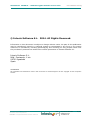
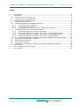
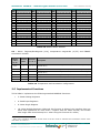
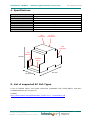
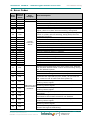
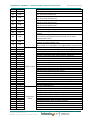
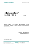
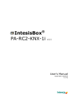
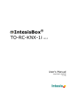
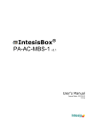
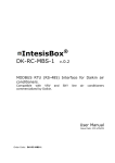
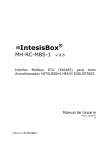
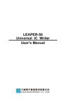
IntesisBox TO-RC-MBS-1 ® v.2.0 MODBUS RTU (EIA485) Interface for Toshiba air conditioners from the Digital Inverter & VRF lines. User Manual Issue Date: 10/2014 Order Codes: TO-RC-MBS-1 IntesisBox® Modbus - Toshiba Digital Inverter & VRF lines User’s Manual r2.0 eng © Intesis Software S.L. 2014. All Rights Reserved. Information in this document is subject to change without notice. No part of this publication may be reproduced, stored in a retrieval system or transmitted in any form or any means electronic or mechanical, including photocopying and recording for any purpose other than the purchaser’s personal use without the written permission of Intesis Software S.L. Intesis Software S.L. Milà i Fontanals, 1 bis 08700 Igualada Spain TRADEMARKS All trademarks and tradenames used in this document are acknowledged to be the copyright of their respective holders. © Intesis Software S.L. - All rights reserved This information is subject to change without notice IntesisBox® is a registered trademark of Intesis Software SL URL Email tel http://www.intesis.com [email protected] +34 938047134 2 / 23 IntesisBox® Modbus - Toshiba Digital Inverter & VRF lines User’s Manual r2.0 eng INDEX 1. Presentation .................................................................................................... 4 2. Connection ...................................................................................................... 5 2.1 Connect to the AC indoor unit ......................................................................... 5 2.2 Connection to the EIA485 bus ......................................................................... 5 3. Modbus Interface Specification ........................................................................... 6 3.1 Modbus physical layer .................................................................................... 6 3.2 Modbus Registers for Standard Functions ......................................................... 6 3.2.1 Control and status registers ...................................................................... 6 3.2.2 Configuration Registers ............................................................................ 7 3.2.3 Considerations on TO-RC-MBS-1 temperature registers ................................ 8 3.3 Modbus Registers for Advanced Functions ...................................................... 11 3.3.1 Advanced registers for Indoor Unit status ................................................. 11 3.3.2 Advanced registers for Outdoor Unit status on VRF-SHRM systems .............. 12 3.3.3 Advanced registers for Outdoor Unit status on VRF-SMMS systems .............. 13 3.3.4 Advanced registers for Outdoor Unit status on RAV systems ....................... 14 3.3.5 Advanced registers for Indoor Unit Type and Refresh Time adjustment ........ 15 3.4 DIP-switch Configuration Interface ................................................................ 16 3.5 Implemented Functions ................................................................................ 17 3.6 Device LED indicator .................................................................................... 18 3.7 EIA485 bus. Termination resistors and Fail Safe Biasing mechanism .................. 18 4. Specifications................................................................................................. 19 5. List of supported AC Unit Types ........................................................................ 19 6. Error Codes ................................................................................................... 20 © Intesis Software S.L. - All rights reserved This information is subject to change without notice IntesisBox® is a registered trademark of Intesis Software SL URL Email tel http://www.intesis.com [email protected] +34 938047134 3 / 23 IntesisBox® Modbus - Toshiba Digital Inverter & VRF lines User’s Manual r2.0 eng 1. Presentation The TO-RC-MBS-1 interface allows a complete and natural integration of Toshiba air conditioners into Modbus RTU (EIA485) networks. The TO-RC-MBS-1 is compatible with the Toshiba Digital Inverter & VRF lines. Reduced dimensions. 93 x 53 x 58 mm. Quick and easy installation. Mountable on DIN rail, wall, or even inside the indoor unit in some models of AC. External power not required. Direct connection to MODBUS RTU (EIA485) networks. TO-RC-MBS-1 is a Modbus slave device. Direct connection to the AC indoor unit. Configuration from both on-board DIP-switches and MODBUS RTU. Total Control and Supervision. Real states of the AC unit's internal variables. Allows using simultaneously the control panel and MODBUS RTU. Modbus RTU EIA485 network Modbus RTU master device TO-RC-MBS-1 Up to 63 AC indoor units TO-RC-MBS-1 SCADA PLC DDC BMS HMI Controller etc TO-RC-MBS-1 © Intesis Software S.L. - All rights reserved This information is subject to change without notice IntesisBox® is a registered trademark of Intesis Software SL URL Email tel http://www.intesis.com [email protected] +34 938047134 4 / 23 IntesisBox® Modbus - Toshiba Digital Inverter & VRF lines User’s Manual r2.0 eng 2. Connection The interface comes with two plug-in terminal blocks of 2 poles for connection to a Modbus RTU EIA485 network and to the Toshiba AB bus. (It is not mandatory to have it in the network) Control Panel Toshiba AC Indoor Unit AB AC Unit A B IntesisBox® TO-RC-MBS-1 EIA485 Internal electronic control board A+ B- A B MODBUS RTU EIA485 Bus Max. 500 m 2.1 Connect to the AC indoor unit To connect the TO-RC-MBS-1 interface to the AC indoor unit follow these steps: Disconnect mains power from the AC unit. Open the front cover of the indoor unit in order to have access to the electronic circuit. In the electronic circuit locate the socket connector marked as AB1: Using a cable connect the interface to AB bus in any point of the bus. The AB bus is the bus that connects the AC indoor unit and the wired remote controller, is a two-wire bus connecting terminals AB of both and has no specific polarity. Respect the maximum distance of 500 m for the bus length. IMPORTANT: In case of having a Toshiba’s Control Panel (not mandatory), DIP switch of the Toshiba Control Panel should be always set into Follower position. 12 Switches 1 2 Back view of the Toshiba’s Control Panel Function Toshiba’s remote controller as Follower. 2.2 Connection to the EIA485 bus Connect the EIA485 bus wires to the plug-in terminal block (the one of two poles) of TO-RCMBS-1, respect the polarity on this connection (A+ and B-). Respect the maximum distance of 1200 meters for the bus, no loop or star topologies are allowed for EIA485 bus, a terminator resistor of 120 Ω must be present at each end of the bus to avoid signal reflections and also a fail-safe biasing mechanism (see section 3.7 for more details). 1 In some models, the AB connector is not present. Find the Control Panel (remote controller) bus and connect the cable coming from the IntesisBox gateway into these cables as if they were the AB connector. © Intesis Software S.L. - All rights reserved This information is subject to change without notice IntesisBox® is a registered trademark of Intesis Software SL URL Email tel http://www.intesis.com [email protected] +34 938047134 5 / 23 IntesisBox® Modbus - Toshiba Digital Inverter & VRF lines User’s Manual r2.0 eng 3. Modbus Interface Specification 3.1 Modbus physical layer TO-RC-MBS-1 implements a MODBUS RTU (slave) interface, to be connected to an EIA485 line. It performs 8N2 (8N1-compatible) communication (8 data bits, no parity and 2 stop bit) with several available baud rates (2400 bps, 9600 bps -default-, 19200 bps and 57600 bps). 3.2 Modbus Registers for Standard Functions All registers are of type “16-bit signed Holding Register”, in standard ModBus’ big endian notation. 3.2.1 Control and status registers Register Addr (protocol address) Register Addr (PLC address) R/W 0 1 R/W Description AC unit On/Off 0: Off 1: On AC unit Mode 1 2 R/W 0: 1: 2: 3: 4: Auto Heat Dry Fan Cool AC unit Fan Speed 2 3 R/W 0: 1: 2: 3: Auto Low Mid High AC unit Vane Position 3 4 R/W 4 5 R/W 5 6 R 6 7 R/W 0: Vane Off (Stand-by) 1: POS1 (Horizontal) 2: POS2 (Horizontal) 3: POS3 (Med) 4: POS4 (Vert) 5: POS5 (Vert) 10: SWING AC unit Temperature Setpoint (ºC/ºF) (ºC/x10ºC/F)2 See section 3.2.3 below. AC unit Ambient Temperature (ºC/ºF) (ºC/x10ºC/F)2 See section 3.2.3 below. Window Contact 0: Closed 1: Open Modbus Command Disablement3 7 8 R/W 2 3 0: Modbus Commands enabled (default) 1: Modbus Commands disabled (device in monitor-only mode) Magnitude for this register can be adjusted to Celsius x 1ºC, Celsius x 10ºC (default) or Fahrenheit through DIP switches Value of this register is stored in non-volatile memory (EEPROM) © Intesis Software S.L. - All rights reserved This information is subject to change without notice IntesisBox® is a registered trademark of Intesis Software SL URL Email tel http://www.intesis.com [email protected] +34 938047134 6 / 23 IntesisBox® Modbus - Toshiba Digital Inverter & VRF lines 8 9 R/W 9 10 R/W 10 11 R 11 12 R User’s Manual r2.0 eng Remote Command Disablement 0: Remote Command enabled 1: Remote Command disabled AC unit Operation Time3 0..65535 (hours). Counts the time the AC unit is in “On” state. AC unit Alarm Status 0: No alarm condition 1: Alarm condition Error Code Indoor unit ambient temperature from external sensor (at Modbus side) 22 23 R/W -32768: Default value. No temperature is being provided from an external sensor. Any other: (ºC/x10ºC/ºF)4 See section 3.2.3 below. Current setpoint in AC indoor unit 23 24 R (ºC/x10ºC/F)2 This read-only register shows the setpoint of the indoor unit: when register “indoor unit ambient temperature from external sensor” (23 in PLC addressing) is not used, value for register 24 and register 5 will be the same. See section 3.2.3 below. 3.2.2 Configuration Registers Register Addr (protocol address) Register Addr (PLC address) R/W Description 12 13 R/W Reserved 13 14 R/W “Open Window” switch-off timeout 0..30 (minutes) Factory setting: 30 (minutes) Modbus RTU baud-rate (bps) 4 14 15 R 15 16 R 21 22 R 49 50 R 50 51 R 2400 4800 9600 19200 Device's Modbus slave address 1..63 Max number of fan speeds 3 (fixed value) Device Identification TO-RC-MBS-1: 0x1500 (5376d) Software version Magnitude for this register can be adjusted to Celsius x 1ºC, Celsius x 10ºC (default) or Fahrenheit through DIP switches S4 © Intesis Software S.L. - All rights reserved This information is subject to change without notice IntesisBox® is a registered trademark of Intesis Software SL URL Email tel http://www.intesis.com [email protected] +34 938047134 7 / 23 IntesisBox® Modbus - Toshiba Digital Inverter & VRF lines User’s Manual r2.0 eng 3.2.3 Considerations on TO-RC-MBS-1 temperature registers TO-RC-MBS-1 implements four registers containing temperature values: AC unit Temperature Setpoint (R/W) (register 5 – in PLC addressing): This is the adjustable temperature setpoint meant to be required by the user. This register can be read (Modbus function 3 or 4) or written (modbus functions 5 or 16). A remote controller connected to the AB bus of the Toshiba indoor unit will report the same temperature setpoint value as this register only when no AC unit external reference is provided from TO-RC-MBS-1 (see detail for register 23 below). AC unit ambient temperature temperature (R) (register 6 – in PLC addressing): This register reports the temperature that is actually used by the Toshiba indoor unit as reference of its own control loop. Depending on the configuration of the indoor unit, this can be the temperature reported by the sensor in in the return path of the Toshiba indoor unit or the sensor of an additional remote controller in the AB bus. It is a read-only register (modbus functions 3 or 4). AC unit external temperature reference (R/W) (register 23 – in PLC addressing): This register allows providing an external temperature reference from modbus side. AB does not directly allow for devices like TO-RC-MBS-1 to directly provide a temperature to be used as reference of the control loop of the AC indoor unit. In order to overcome that limitation and enable usage of an external temperature sensor (i.e. in Modbus side), TO-RC-MBS-1 applies following mechanism (if and only if “external reference temperature” is being used): o After a couple of values are entered in the “AC unit external reference temperature” (register 23) and “AC unit temperature setpoint” (register 5), TO-RC-MBS-1 will calculate the temperature demand they imply. (e.g. if a “temperature setpoint (register 5)” of 22ºC, and an “external temperature reference (register 23)” of 20ºC are entered, TO-RC-MBS-1 will assume that the user is demanding a +2ºC increase in temperature). o By knowing at all times the ambient temperature actually used by the indoor unit to control its own operation (register 6), TO-RC-MBS-1 can calculate the required setpoint so to apply the demand desired by the user (following the example above, if TO-RC-MBS-1 reads an “ambient temperature” (register 6) of 24ºC in the indoor unit, it will apply a final setpoint of 24ºC + 2ºC = 26ºC). o From this point on, whenever TO-RC-MBS-1 detects that the ambient temperature reported by the indoor unit changes (register 6), it will also change the required setpoint accordingly, in order to keep the demand required by the user at any time (following the example above, if TO-RCMBS-1 receives a new value for temperature coming from the indoor unit pf 25ºC, TO-RC-MBS-1 will automatically adjust the setpoint required to the AC indoor unit to 25ºC + 2ºC = 27ºC) o In general, TO-RC-MBS-1 is constantly applying the following formula: SAC = Su – ( Tu – T AC ) Where: SAC - setpoint actually applied to the indoor unit Su - setpoint written at modbus side / TO-RC-MBS-1 register 5 © Intesis Software S.L. - All rights reserved This information is subject to change without notice IntesisBox® is a registered trademark of Intesis Software SL URL Email tel http://www.intesis.com [email protected] +34 938047134 8 / 23 IntesisBox® Modbus - Toshiba Digital Inverter & VRF lines User’s Manual r2.0 eng Tu - external temperature reference written at Modbus side / PA-RCMBS-1 register 23 TAC - ambient temperature that the indoor unit is using as reference of its own control loop register 6 Whenever TO-RC-MBS-1 detects a change in any of the values of { Su , Tu , TAC }, it will send the new corresponding setpoint (SAC) to the indoor unit. o After startup, value for “external temperature reference” (register 23) has value -32768 (0x8000). This value means that no external temperature is being provided through TO-RC-MBS-1. In this scenario, setpoint shown or written in register 5 will always have same value as the actual setpoint of the indoor unit. o Note that, using the “external temperature reference” (register 23) (i.e. writing a value different from -32768 / 0x8000 in it) has following relevant consequences: Setpoint reported by any additional remote controller or monitoring device from Toshiba in AB, in general will be different from the one entered in register 5 of TO-RC-MBS-1, since the mechanism above is being applied. User will not be able to change setpoint using any remote controller from Toshiba, as setpoint of the indoor unit will become exclusively controlled by the mechanism explained above (i.e. the setpoint obtained in that mechanism will always be enforced in the indoor unit). Current setpoint in AC indoor unit (R) (register 24 – in PLC addressing): As detailed in previous point, actual setpoint in the indoor unit and setpoint requested from TO-RC-MBS-1 might differ (when a value in register 23 – “external temperature reference” is put). This register always informs of the actual setpoint being used by the indoor unit – this is also the setpoint that will show an additional remote controller from Toshiba in the AB bus. Additionally, note that temperature values all these three registers are expressed according to the temperature format configured through its onboard DIP-Switches (See “3.4 - © Intesis Software S.L. - All rights reserved This information is subject to change without notice IntesisBox® is a registered trademark of Intesis Software SL URL Email tel http://www.intesis.com [email protected] +34 938047134 9 / 23 IntesisBox® Modbus - Toshiba Digital Inverter & VRF lines User’s Manual r2.0 eng DIP-switch Configuration Interface”). Following formats are possible: Celsius value: Value in Modbus register is the temperature value in Celsius (i.e. a value “22” in the Modbus register must be interpreted as 22ºC) Decicelsius value: Value in Modbus register is the temperature value in decicelsius (i.e. a value “220” in the Modbus register must be interpreted as 22.0ºC) Fahrenheit value: Value in Modbus register is the temperature value in Fahrenheit (i.e. a value “72” in the Modbus register must be interpreted as 72ºF (~22ºC). © Intesis Software S.L. - All rights reserved This information is subject to change without notice IntesisBox® is a registered trademark of Intesis Software SL URL Email tel http://www.intesis.com [email protected] +34 938047134 10 / 23 IntesisBox® Modbus - Toshiba Digital Inverter & VRF lines User’s Manual r2.0 eng 3.3 Modbus Registers for Advanced Functions 3.3.1 Advanced registers for Indoor Unit status These registers are only available when the indoor unit type selected on S1 is different from default. Please, check section 3.4 for more information. Register Addr (protocol address) Register Addr (IU - 1) * 25 + 4000 (IU - 1) * 25 + 4001 R (IU - 1) * 25 + 4001 (IU - 1) * 25 + 4002 R (IU - 1) * 25 + 4002 (IU - 1) * 25 + 4003 R (IU - 1) * 25 + 4003 (IU - 1) * 25 + 4004 R (IU - 1) * 25 + 4004 (IU - 1) * 25 + 4005 R (IU - 1) * 25 + 4005 (IU - 1) * 25 + 4006 R (IU - 1) * 25 + 4010 (IU - 1) * 25 + 4011 R Room temperature (During Control) R Room temperature (Remote Controller) (PLC address) R/W Description IU exist (IU - 1) * 25 + 4012 (IU - 1) * 25 + 4013 R (IU - 1) * 25 + 4014 R (IU - 1) * 25 + 4014 (IU - 1) * 25 + 4015 R (IU - 1) * 25 + 4015 (IU - 1) * 25 + 4016 R (IU - 1) * 25 + 4016 (IU - 1) * 25 + 4017 R (IU - 1) * 25 + 4017 (IU - 1) * 25 + 4018 R (IU - 1) * 25 + 4018 (IU - 1) * 25 + 4019 R (IU - 1) * 25 + 4019 (IU - 1) * 25 + 4020 R © Intesis Software S.L. - All rights reserved This information is subject to change without notice IntesisBox® is a registered trademark of Intesis Software SL 0 0 1 0..15 IU defrost 1 0: Off 1: On IU filter alarm 0: No alarm 1: Alarm 1 IU thermo ON 1 0: Cool 1: Heat x1 ºC x1 ºC Indoor coil temperature (TC1) x1 ºC Indoor discharge temperature (TF) 1 x1 ºC Indoor coil temperature (TC2) 2 x1 ºC Indoor coil temperature (TCJ) 2 x1 ºC Indoor suction temperature (TA) (IU - 1) * 25 + 4013 MSB - OU address ; LSB - IU address IU duty (IU - 1) * 25 + 4012 0: Doesn’t exist 1: Exist IU address (IU - 1) * 25 + 4011 Priority x1 ºC Only for VRF systems 1 1 1 0 Revolutions indoor fan RPS Only for RAV systems 0 Indoor PMV opening x1, x10 Pulses Only for VRF systems Running hours indoor fan URL Email tel http://www.intesis.com [email protected] +34 938047134 1 0 11 / 23 IntesisBox® Modbus - Toshiba Digital Inverter & VRF lines (IU - 1) * 25 + 4020 (IU - 1) * 25 + 4021 (IU - 1) * 25 + 4021 (IU - 1) * 25 + 4022 User’s Manual r2.0 eng x100 hours Only for RAV systems Time filtersign R 0 Hours Only for RAV systems Estimated supply air temperature R 0 x1 ºC Only for RAV systems NOTE: IU stands for the Indoor Unit index (1..8). 3.3.2 Advanced registers for Outdoor Unit status on VRF-SHRM systems These registers are only available when the indoor unit type selected on S1 is different from default. Please, check section 3.4 for more information. Register Addr Register Addr (protocol address) (PLC address) 4200 4201 R 4210 4211 R 4211 4212 R 4212 4213 R 4213 4214 R 4214 4215 R 4215 4216 R 4216 4217 R 4217 4218 R 4218 4219 R 4219 4220 R 4220 4211 R 4221 4222 R 4223 4224 R 4224 4225 R 4225 4226 R © Intesis Software S.L. - All rights reserved This information is subject to change without notice IntesisBox® is a registered trademark of Intesis Software SL R/W Description Priority Outdoor Unit duty 1 15 Td1-Compressor 1 Discharge Temp. x1 ºC Td2-Compressor 2 Discharge Temp. x1 ºC Pd – High Pressure Sensor MPa Ps - Low Pressure Sensor MPa TS – Suction Temp. x1 ºC TL – Liquid Temp. x1 ºC TU – Low Pressure Saturated Temp. x1 ºC Compressor 1 Current A Compressor 2 Current A PMV1 + 2 Opening 2 2 2 2 x1 ºC TO - Outside ambient temperature 2 2 x1 ºC TE - Outdoor Heat Exchanger Temp. 2 1 2 1 2 2 0..100 Compressor 1, 2 2 0: Off 1: On Outdoor Fan Mode 2 0..31 Outdoor Unit Size 2 HP URL Email tel http://www.intesis.com [email protected] +34 938047134 12 / 23 IntesisBox® Modbus - Toshiba Digital Inverter & VRF lines User’s Manual r2.0 eng 3.3.3 Advanced registers for Outdoor Unit status on VRF-SMMS systems These registers are only available when the indoor unit type selected on S1 is different from default. Please, check section 3.4 for more information. Register Addr Register Addr (protocol address) (PLC address) 4200 4201 R Outdoor Unit duty 4210 4211 R High-pressure pressure (Pd) R/W Description 4211 4212 R 4213 R 4214 R 4215 R detention sensor detention discharge discharge discharge Suction temperature (TS) 4216 4217 R Outdoor coil temperature 1 (TE1) 4217 4218 R Outdoor coil temperature 2 (TE2) 4218 4219 R Temperature at liquid side (TL) 4219 4220 R Outside ambient temperature (TO) 4220 4221 R PMV1 + 2 opening 4221 4222 R PMV4 opening 4222 4223 R Compressor 1 current (I1) 4223 4224 R Compressor 2 current (I2) 4224 4225 R Compressor 3 current (I3) 4225 4226 R Outdoor fan current (IFan) 4226 4227 R Compressor 1 revolutions 4227 4228 R Compressor 2 revolutions 4228 4229 R Compressor 3 revolutions 4229 4230 R Outdoor fan mode 4230 4231 R Compressor IPDU temperature 4231 4232 R © Intesis Software S.L. - All rights reserved This information is subject to change without notice IntesisBox® is a registered trademark of Intesis Software SL 2 x1 ºC x1 ºC x1 ºC 2 1 2 x1 ºC x1 ºC 1 2 x1 Pulse 2 x1 Pulse 1 x10 A 2 x10 A 2 x10 A 2 x10 A 2 x10 RPS 2 x10 RPS 2 x10 RPS 2 x1 mode 1 heat sink 2 heat sink 2 x1 ºC Compressor IPDU temperature 2 x1 ºC R 2 x1 ºC 4216 2 x1 ºC 4215 2 X100 MPa Compressor 3 temperature (Td3) 2 X100 MPa Compressor 2 temperature (Td2) 4214 sensor Compressor 1 temperature (Td1) 4213 1 15 Low-pressure pressure (Ps) 4212 Priority 2 x1 ºC URL Email tel http://www.intesis.com [email protected] +34 938047134 13 / 23 IntesisBox® Modbus - Toshiba Digital Inverter & VRF lines 4232 4233 R Compressor IPDU temperature 4233 4234 R 4234 4235 R 4235 4236 R 4236 4237 R 4237 4238 R 4238 4239 R 3 heat sink heat sink IPDU recovery 2 0: Normal 1: Recovery controlled Pressure release ∗5 2 0: Normal 1: Recovery controlled Discharge temperature release ∗5 0: Normal 1: Recovery controlled Follower unit release (U2/U2/U4 outdoor units) ∗5 0: Normal 1: Recovery controlled Outdoor unit horsepower 2 x1 ºC Heating/cooling controlled ∗5 2 x1 ºC Outdoor fan temperature User’s Manual r2.0 eng 2 2 0 x1 HP 3.3.4 Advanced registers for Outdoor Unit status on RAV systems These registers are only available when the indoor unit type selected on S1 is different from default. Please, check section 3.4 for more information. Register Addr Register Addr (protocol address) (PLC address) 4400 4401 R 4410 4411 R 4411 4412 R TO temperature outdoor 4412 4413 R Compressor temperature R/W Description Priority OU duty 1 0..15 TE temperature (evaporator) x1 ºC 1 x1 ºC discharge 4414 R Suction temperature TS 4414 4415 R Temperature thyristor THS 4415 4416 R Compressor current 4416 4417 R Temperature at liquid side TL 4417 4418 R Compressor revolutions 4418 4419 R Revolutions lower Fan 4419 4420 R 4420 4221 R © Intesis Software S.L. - All rights reserved This information is subject to change without notice IntesisBox® is a registered trademark of Intesis Software SL x1 ºC x1 ºC x1 ºC RPS RPS x100 hours URL Email tel 2 0 1 A Revolutions upper Fan RPS Running hours compressor 2 x1 ºC 4413 2 http://www.intesis.com [email protected] +34 938047134 2 2 0 0 2 14 / 23 IntesisBox® Modbus - Toshiba Digital Inverter & VRF lines User’s Manual r2.0 eng 3.3.5 Advanced registers for Indoor Unit Type and Refresh Time adjustment These registers are only available when the indoor unit type selected on S1 is different from default. Please, check section 3.4 for more information. Register Addr Register Addr (protocol address) (PLC address) R/W Description Priority Indoor Unit Type 4450 4451 R 4451 4452 R/W 0: Not defined (extra signals disabled) 1: RAV 2: VRF (SMMS) 3: VRF (SHRM) Refresh Time Adjust 1..4 0 - Refresh Time Adjust This parameter indicates the polling cadence when reading priority signals. Priorities are defined as follows and can’t be modified: 0: Update on start-up 1: High priority 2: Low priority The higher the value, the fastest the priority signals will update. The cadence is defined by: 1: One high priority signal and one low priority signal polling. 2: Two high priority signals and one low priority signal polling. 3: Three high priority signals and one low priority signal polling. 4: Four high priority signals and one low priority signal polling. © Intesis Software S.L. - All rights reserved This information is subject to change without notice IntesisBox® is a registered trademark of Intesis Software SL URL Email tel http://www.intesis.com [email protected] +34 938047134 15 / 23 IntesisBox® Modbus - Toshiba Digital Inverter & VRF lines User’s Manual r2.0 eng 3.4 DIP-switch Configuration Interface All configuration values on TO-RC-MBS-1 can be written and read from ModBus interface. Though, some of them can also be setup from its on-board DIP-switch interface. They are DIP-switches S1*, S3* and S4 on the device, in the following location: S1 S1 ON 1 2 3 4 AC UNIT AC Unit IntesisBox® TO-RC-MBS-1 EIA485 A B ON 1 2 3 4 5 6 7 8 ON 1 2 3 4 S3 S4 S4 S3 The following table applies for configuration of the interface through these DIP-switches: S1 – Indoor Unit type Binary value b0…b4 Decimal value Switches 1 2 3 4 00xx 0 x x IU type not defined, (default) 10xx 1 x x RAV 01xx 2 x x VRF-SMMS 11xx 3 x x VRF-SHRM Description Table 3.1 Indoor Unit Type S3 – Modbus protocol: Slave address and baudrate Binary value b0…b8 Decimal value Switches 1 2 3 4 5 6 7 8 xxxxxx00 0 x x x x x x 2400bps xxxxxx10 1 x x x x x x 4800bps xxxxxx01 2 x x x x x x 9600bps (- default value) xxxxxx11 3 x x x x x x 19200bps Description Table 3.2 Modbus baud rate © Intesis Software S.L. - All rights reserved This information is subject to change without notice IntesisBox® is a registered trademark of Intesis Software SL URL Email tel http://www.intesis.com [email protected] +34 938047134 16 / 23 IntesisBox® Modbus - Toshiba Digital Inverter & VRF lines User’s Manual r2.0 eng Add Switches 1 2 3 4 5 6 7 8 Add Switches 1 2 3 4 5 6 7 8 Add Switches 1 2 3 4 5 6 7 8 Add Switches 1 2 3 4 5 6 7 8 0 x x 16 x x 32 x x 48 x x 1* x x 17 x x 33 x x 49 x x 2 x x 18 x x 34 x x 50 x x 3 x x 19 x x 35 x x 51 x x 4 x x 20 x x 36 x x 52 x x 5 x x 21 x x 37 x x 53 x x 6 x x 22 x x 38 x x 54 x x 7 x x 23 x x 39 x x 55 x x 8 x x 24 x x 40 x x 56 x x 9 x x 25 x x 41 x x 57 x x 10 x x 26 x x 42 x x 58 x x 11 x x 27 x x 43 x x 59 x x 12 x x 28 x x 44 x x 60 x x 13 x x 29 x x 45 x x 61 x x 14 x x 30 x x 46 x x 62 x x 15 x x 31 x x 47 x x 63 x x Table 3.3 Modbus Slave address S4 – Other: Degrees/Decidegress (x10), temperature magnitude (ºC/ºF) and EIA485 termination resistor Binary value b0…b4 Decimal value Switches 1 2 3 4 Description 0xxx 0 x x x Temperature values in Modbus register are represented in degrees (x1) (default value) 1xxx 1 x x x Temperature values in Modbus register are represented in decidegrees (x10) x0xx 0 x x x Temperature values in Modbus register are represented in Celsius degrees (default value) x1xx 1 x x x Temperature values in Modbus register are represented in Fahrenheit degrees xxx0 0 x x x EIA485 bus without termination resistor (default value) xxx1 1 x x x Internal termination resistor of 120Ω connected to EIA485 bus** Table 3.4 Temperature and termination configuration 3.5 Implemented Functions TO-RC-MBS-1 implements the following standard MODBUS functions: * 3: Read Holding Registers 4: Read Input Registers 6: Write Single Register 16: Write Multiple Registers (Although this function is allowed, the interface does not allow write operations on more than 1 register with the same request, this means that length field should always be 1 when using this function for writes) Default value Only in the interfaces connected at both ends of the bus must be activated the termination resistor. More information in section 3.7 ** © Intesis Software S.L. - All rights reserved This information is subject to change without notice IntesisBox® is a registered trademark of Intesis Software SL URL Email tel http://www.intesis.com [email protected] +34 938047134 17 / 23 IntesisBox® Modbus - Toshiba Digital Inverter & VRF lines User’s Manual r2.0 eng 3.6 Device LED indicator The device includes two LED indicators to signal its different possible operational states. In this section their meaning is explained L1 (yellow) Operation ON Blinking 500 ms Flashing 100 ms L1 (yellow) & L2 (red) Operation ON Pulse 5 sec Alternate blinking 500 ms 3.7 EIA485 bus. mechanism OFF 500 ms 1900 ms OFF -500 ms Termination Meaning Communication error Normal operation (configured and working) Meaning Device start-up EEPROM failure resistors and Fail Safe Biasing EIA485 bus requires a 120Ω terminator resistor at each end of the bus to avoid signal reflections. In order to prevent fail status detections by the receivers "listening" the bus when all the transmitters outputs are in three-state (high impedance), it is also required a fail-safe biasing mechanism. This mechanism provides a safe status (a correct voltage level) in the bus when all the transmitters’ outputs are in three-state. The TO-RC-MBS-1 device includes an on-board terminator resistor of 120Ω that can be connected to the EIA485 bus by using DIP-switch P5 (see below). Fail safe biasing of the EIA485 bus must only be supplied by one of the devices connected to the bus. The device providing fail safe biasing or terminator resistor should be the one connected at one end of the bus. At the other end of the bus, if there is also a TO-RC-MBS1 device, select the 120Ω terminator resistor through DIP-switch P5, or if there is a master device not providing internal 120Ω terminator resistor, connect an external 120Ω resistor in the bus terminal block connection of such master device. Some Modbus RTU EIA485 master devices can provide also internal 120Ω terminator resistor and/or fail safe biasing (consult the technical documentation of the master device connected to the EIA485 network in every case). © Intesis Software S.L. - All rights reserved This information is subject to change without notice IntesisBox® is a registered trademark of Intesis Software SL URL Email tel http://www.intesis.com [email protected] +34 938047134 18 / 23 IntesisBox® Modbus - Toshiba Digital Inverter & VRF lines User’s Manual r2.0 eng 4. Specifications Dimensions: Weight: Operating Temperature: Stock Temperature: Operating Humidity: Stock Humidity: Isolation voltage: Isolation resistance: Modbus Media: 93 x 53 x 58 mm 85 g 0 . . . 40ºC 0 . . . 40ºC <95% RH, non-condensing <95% RH, non-condensing 1000 VDC 1000 MΩ Compatible with Modbus RTU - EIA485 networks LED Indicator AC Unit connection DIP Switches DIP Switches 58 mm EIA485 Port 53 mm 93 mm 5. List of supported AC Unit Types A list of Toshiba indoor unit model references compatible with TO-RC-MBS-1 and their available features can be found in: Toshiba: http://www.intesis.com/pdf/IntesisBox_TO-RC-xxx-1_Compatibility.pdf © Intesis Software S.L. - All rights reserved This information is subject to change without notice IntesisBox® is a registered trademark of Intesis Software SL URL Email tel http://www.intesis.com [email protected] +34 938047134 19 / 23 IntesisBox® Modbus - Toshiba Digital Inverter & VRF lines User’s Manual r2.0 eng 6. Error Codes Error Code Error in Control Panel 0 21 22 23 24 N/A C01 C02 C03 C04 25 C05 26 C06 2C 30 31 32 33 34 35 36 37 38 39 3A 3C 3D 3F C12 C16 C17 C18 C19 C20 C21 C22 C23 C24 C25 C26 C28 C29 C31 41 E01 42 43 E02 E03 44 E04 45 E05 46 E06 47 E07 48 E08 49 E09 4A E10 4B E11 4C E12 Error category TO-RC-MBS-1 Error Description No active error Duplicated setting of control address Central control number of units mis-matched Incorrect wiring of central control Incorrect connection of central control System Controller fault, error in transmitting comms signal, i/door or o/door unit not working, wiring fault System Controller fault, error in receiving comms signal, i/door or o/door unit not working, wiring fault, CN1 not connected correctly Batch alarm by local controller Transmission error from adaptor to unit Central Reception error to adaptor from unit Controller Duplicate central address in adaptor Issues Duplicate adaptor address Mix of PAC & GHP type units on adaptor Memory fault in adaptor Incorrect address setting in adaptor Host terminal software failure Host terminal hardware failure Host terminal processing failure Host terminal communication failure Reception error of S-DDC from host terminal Initialization failure of S-DDC Configuration change detected by adaptor Remote control detecting error from indoor unit, Address not set/Auto address failed. Check interconnecting wiring etc. Re-address system. Remote detecting error from indoor unit, Indoor unit detecting error from remote, Indoor seeing error from outdoor. Qty of i/d units connected are less than qty set. Check; all i/d units are ON, reset turn off all units wait 5min power up Indoor unit detecting error from outdoor unit, Error in sending comms signal Outdoor unit detecting error from indoor unit, Error in Addressing and receiving comms signal Communication Outdoor unit detecting error from indoor unit, Error in Problems sending comms signal Incorrect setting indoor/controller, Indoor address duplicated Incorrect setting indoor/controller, Remote address duplicated or IR wireless controller not disabled Indoor unit detecting error from 'option' plug, Error in sending comms signal Indoor unit detecting error from 'option' plug, Error in receiving comms signal Auto addressing failed, Auto address connector CN100 shorted during auto addressing © Intesis Software S.L. - All rights reserved This information is subject to change without notice IntesisBox® is a registered trademark of Intesis Software SL URL Email tel http://www.intesis.com [email protected] +34 938047134 20 / 23 IntesisBox® Modbus - Toshiba Digital Inverter & VRF lines 4D 4E E13 E14 4F E15 50 E16 51 E17 52 E18 54 58 E20 E24 59 E25 5A E26 5D E29 5F E31 61 62 63 64 65 66 67 68 6A 6B 6C 6D 70 71 72 74 77 78 7D 7E 7F 81 82 83 85 86 87 88 8B 8C 8D 8F 95 F01 F02 F03 F04 F05 F06 F07 F08 F10 F11 F12 F13 F16 F17 F18 F20 F23 F24 F29 F30 F31 H01 H02 H03 H05 H06 H07 H08 H11 H12 H13 H15 H21 Sensor Faults Compressor Issues User’s Manual r2.0 eng Indoor unit failed to send signal to remote controller Setting Failure, Duplication of master indoor units Auto addressing failed, Number of indoor units connected are less than number set Auto addressing failed, Number of indoor units connected are more than number set Group control wiring error, Main indoor unit not sending signal for sub indoor units Group control wiring error, Main indoor unit not receiving signal for sub indoor units Auto addressing failed, No indoor units connected Auto addressing failed, Error on sub outdoor unit Auto addressing failed, Error on outdoor unit address setting Auto addressing failed, Quantity of main and sub outdoor units do not correspond to the number set on main outdoor unit P.C.B. Auto addressing failed, Sub outdoor unit not receiving comms for main outdoor unit Between units, Comms failure with MDC, does E31 remain after power is re-instated? If so replace PCB. & power PCB Indoor Heat Exch inlet temp sensor failure (E1) Indoor Heat Exch freeze temp sensor failure (E2) Indoor Heat Exch outlet temp sensor failure (E3) Outdoor Discharge temp sensor failure (TD) or (DISCH1) Outdoor Discharge temp sensor failure (DISCH2) Outdoor Heat Exch temp sensor failure (C1) or (EXG1) Outdoor Heat Exch temp sensor failure (C2) or (EXL1) Outdoor Air temp sensor failure (TO) Indoor inlet temp sensor failure Indoor outlet temp sensor failure Outdoor Intake sensor failure (TS) GHP - Cooling water temperature sensor failure Outdoor High pressure sensor failure GHP - Cooling water temperature sensor fault GHP - Exhaust gas temperature sensor fault GHP Clutch coil temperature fault Outdoor Heat Exch temp sensor failure (EXG2) Outdoor Heat Exch temp sensor failure (EXL2) Indoor EEPROM error Clock Function (RTC) fault Outdoor EEPROM error Compressor Fault, Over current (Comp1) Compressor Fault, Locked rota current detected (Comp1) Compressor Fault, No current detected (Comp1) Compressor Fault, Discharge temp not detected (Comp1) Compressor Fault, Low Pressure trip Compressor Fault, Low oil level Compressor Fault, Oil sensor Fault (Comp1) Compressor Fault, Over current (Comp2) Compressor Fault, Locked rota current detected (Comp2) Compressor Fault, No current detected (Comp2) Compressor Fault, Discharge temp not detected (Comp2) Compressor Fault, Over current (Comp3) © Intesis Software S.L. - All rights reserved This information is subject to change without notice IntesisBox® is a registered trademark of Intesis Software SL URL Email tel http://www.intesis.com [email protected] +34 938047134 21 / 23 IntesisBox® Modbus - Toshiba Digital Inverter & VRF lines 96 97 99 9B 9C 9F C1 H22 H23 H25 H27 H28 H31 L01 C2 L02 C3 C4 L03 L04 C5 L05 C6 L06 C7 C8 C9 CA CB CD CF D0 D1 D2 D3 D5 E1 L07 L08 L09 L10 L11 L13 L15 L16 L17 L18 L19 L21 P01 E2 P02 E3 P03 E4 P04 E5 P05 E9 EA EB EC EE P09 P10 P11 P12 P14 EF P15 F0 P16 F1 P17 F2 P18 F3 P19 F4 P20 Incorrect Settings Indoor Unit Problems User’s Manual r2.0 eng Compressor Fault, Locked rota current detected (Comp3) Compressor Fault, No current detected (Comp3) Compressor Fault, Discharge temp not detected (Comp3) Compressor Fault, Oil sensor fault (Comp2) Compressor Fault. Oil sensor (connection failure) Compressor Fault. IPM trip (IMP current on temperature) Setting Error, Indoor unit group setting error Setting Error, Indoor/outdoor unit type/model missmatched Duplication of main indoor unit address in group control Duplication of outdoor unit system address 2 or more controllers have been set as 'priority' in one system - shown on controllers set as 'priority' 2 or more controllers have been set as 'priority' in one system - shown on controllers not set as 'priority' Group wiring connected on and individual indoor unit Indoor unit address/group not set Indoor unit capacity code not set Outdoor unit capacity code not set Group control wiring incorrect Indoor unit type setting error, capacity Indoor unit paring fault Water heat exch unit setting failure Miss-match of outdoor unit with different refrigerant 4-way valve failure Water heat exch unit duplicated address Gas type setup failure Indoor unit fault, Fan motor thermal overload Outdoor unit fault, Compressor motor thermal overload, over or under voltage Outdoor unit fault, Compressor discharge temperature too high (Comp1) over 111 ºC. Low on ref gas, exp valve, pipework damage. Outdoor unit fault, High pressure trip Outdoor unit fault, Open phase on power supply. Check power on each phase, inverter pcb, control pcb Indoor unit fault, Ceiling panel incorrectly wired Indoor unit fault, Condensate float switch opened GHP - Water Heat exch low temp (frost protection) fault Indoor unit fault, Fan DC motor fault Input from leak detector (If fitted) Refrigerant loss, high discharge temp and EEV wide open and low compressor current draw. Outdoor unit fault, Open phase on compressor power supply Outdoor unit fault, Compressor discharge temperature too high (Comp2) over 111 degC. Low on ref gas, exp valve, pipework damage. Outdoor unit fault, By-pass valve failure Outdoor unit fault, 4 way valve failure, i/door temp rises in cooling or fills in heating. Check wiring, coil, pcb output, valve operation. Ref gas, high temp/pressure fault, heat exch temp high C2, 55-60 degC, cooling over-load, sensor fault. © Intesis Software S.L. - All rights reserved This information is subject to change without notice IntesisBox® is a registered trademark of Intesis Software SL URL Email tel http://www.intesis.com [email protected] +34 938047134 22 / 23 IntesisBox® Modbus - Toshiba Digital Inverter & VRF lines F6 P22 FA P26 FC P29 FD P30 FF P31 65535 (-1) N/A TO-RC-MBS-1 User’s Manual r2.0 eng Outdoor unit fan motor fault, fan blade jammed, check connections, does fan turn freely, motor resistance 3040ohm on each pair, no fan fault, yes pcb fault. Outdoor unit fault, Compressor overcurrent - check winding resistance, Inverter failure - check internal resistance term HIC + & - to UVW 200-300Kohm or more Outdoor unit fault, Inverter circuit fault - Motor-current Detection Circuit (MDC) fault, check comp windings, sensors C1 & TS, if ok possible pcb failure. Indoor unit fault, System controller detected fault on sub indoor unit Simultaneous operation multi control fault, Group controller fault Error in the communication of TO-RC-MBS-1device with the AC unit In case you detect an error code not listed, contact your nearest Toshiba technical support service. © Intesis Software S.L. - All rights reserved This information is subject to change without notice IntesisBox® is a registered trademark of Intesis Software SL URL Email tel http://www.intesis.com [email protected] +34 938047134 23 / 23