1
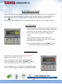
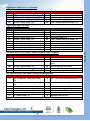
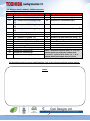
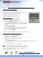
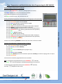
Pocket Quick Reference Guide On the TOSHIBA RBC-AMT32E / RBC-AMS41E Remote Controllers Cool Designs Ltd makes every effort to ensure that the information provided within this publication is correct and error free, however we cannot guarantee that it is free of inaccuracies, errors or omissions. Users should seek to clarify this information for themselves prior to basing any decisions upon such information. Quick Reference Guide To assist service engineers working on Toshiba air conditioning equipment, there is a large quantity of data available via the standard remote controller, either the RBC-AMT32E or the RBC-AMS41E, this data is NOT available via an Infrared remote or the RBC-AS21E2 simplified remote controller. Accessing the data is a simple process of pressing a sequence of buttons on the remote controller. Fault Code Guide Current fault codes are displayed automatically on the left of the remote controller, (Four figure display in Black) fault code history can be accessed by pressing “Test and Set” (The two yellow buttons) together and holding for 4 seconds. Each controller will hold four fault codes per unit controlled, the first displayed fault code is the youngest and the fourth will be the oldest. To scroll through the faults use the “TEMP” buttons. Refer to the Technical Handbook for fault code diagnosis and descriptions Data Retrieval Guide System data can be obtained by pressing “Test and CL” together and holding for 4 seconds Codes are displayed on the right of the remote display To scroll through the codes use the “TEMP ” buttons. Data is displayed on the left of the remote controller. Data is available for “0, 1, 2, 3 & 4 Series” Digital/Super Digital Inverter and VRF equipment (SMMS, SHRM, SMMSI & SHRMi). Cool Designs Ltd makes every effort to ensure that the information provided within this publication is correct and error free, however we cannot guarantee that it is free of inaccuracies, errors or omissions. Users should seek to clarify this information for themselves prior to basing any decisions upon such information. Digital/Super digital “0-1-2-3” series data Code 00 01 02 03 04 Indoor Data Room Temp (Control Temp) (oC) Room Temp. (Remote Controller) (oC) TA Return Air Temp. (oC) TC Coil – Vapour Temp. (oC) TCJ Coil – Liquid Temp. (oC) Digital/Super digital “4” series Code Indoor Data 00 Room Temp (Control Temp) (oC) 01 Room Temp. (Remote Controller) (oC) 02 TA Return Air Temp. (oC) 03 TC Coil – Vapour Temp. (oC) 04 TCJ Coil – Liquid Temp. (oC) 07 Fan Speed (rpm) F2 Fan Run Time (x 100h) F3 Filter Duration Timer ( x 1h) F8 Discharge Temp. (Indoor – If fitted) (oC) Code 60 61 62 63 65 Outdoor Data TE Sub-cooled Liquid Temp. (oC) TO Ambient Temp. (oC) TD Discharge Temp. (oC) TS Suction Temp. (oC) THS – Inverter Heat Sink Temp. (oC) Code 60 61 62 63 65 6A 70 72 73 F1 Outdoor Data TE Sub-cooled Liquid Temp. (oC) TO Ambient Temp. (oC) TD Discharge Temp. (oC) TS Suction Temp. (oC) THS – Inverter Heat Sink Temp. (oC) Operation Current (A) Compressor Frequency (Hz) Fan Speed (Lower) – (rpm) Fan Speed (Upper) – (rpm) Compressor Run Time (x 100h) Data Retrieval VRF indoor data for Mini SMMS / SMMS / SMMSI & SHRM equipment Code Indoor Data Code Indoor Data o 00 Room Temp (Control Temp) ( C) 06 Indoor Discharge Temp (If Used) - (oC) 01 Room Temp. (Remote Controller) (oC) 08 PMV Position (0 – 10) o 02 TA Return Air Temp. ( C) 0A Number of Connected Indoor Units (No.) o 03 TCJ Coil – Liquid Temp. ( C) 0b Indoor Capacity (x 10 = HP) o 04 TC2 Coil – PMV Pipe Temp. ( C) 0C Number of Outdoor Units (No.) o 05 TC1 Coil – Vapour Temp ( C) 0d Outdoor Capacity ( x 10 = HP) VRF Outdoor data for Mini SMMS / SMMS & SHRM equipment Code Outdoor Data Code Outdoor Data *0 Td1 - Compressor 1 Discharge Temp. *8 TU – Low Pressure Saturated Temp. (oC) (oC) *1 Td2 - Compressor 2 Discharge Temp. *9 Compressor 1 Current (A) (oC) *2 Pd – High Pressure Sensor (MPa) *A Compressor 2 Current (A) *3 Ps - Low Pressure Sensor (MPa) *b PMV1 + 2 Opening (0 – 100) o *4 TS – Suction Temp. ( C) *d Compressor 1, 2 ON/OFF *5 TE - Outdoor Heat Exchanger Temp. (oC) *E Outdoor Fan Mode (0 – 31) o *6 TL – Liquid Temp. ( C) *F Outdoor Unit Size (HP) Note. * Would be replaced with 1, 2, 3 or 4 to obtain data from respective outdoor unit. Cool Designs Ltd makes every effort to ensure that the information provided within this publication is correct and error free, however we cannot guarantee that it is free of inaccuracies, errors or omissions. Users should seek to clarify this information for themselves prior to basing any decisions upon such information. VRF Outdoor data for SMMSi / SHRMi equipment Code *0 *1 *2 *3 *4 *5 *6 *7 *8 *9 *A *B *C *D *E *F Outdoor Data Pd – High Pressure Sensor (MPa) Ps – Low Pressure Sensor (MPa) Td1 – Compressor 1 Discharge Temp. (oC) Td2 – Compressor 2 Discharge Temp. (oC) Td3 – Compressor 3 Discharge Temp. (oC) TS – Suction Temp. (oC) TE1 – Outdoor Coil Temp. (oC) TE2 – Outdoor Coil Temp. (oC) TL – Liquid Temp. (oC) TO – Outdoor Ambient Temp. (oC) PMV 1 + 2 Opening PMV 4 Opening Compressor 1 Current (A) Compressor 2 Current (A) Compressor 3 Current (A) Outdoor Fan Current (A) Code #0 #1 #2 Outdoor Data Compressor 1 Revolutions (rps) Compressor 2 Revolutions (rps) Compressor 3 Revolutions (rps) #3 Outdoor Fan Mode #4 Compressor IPDU 1 Heat Sink Temp. (oC) #5 Compressor IPDU 2 Heat Sink Temp. (oC) #6 Compressor IPDU 3 Heat Sink Temp. (oC) #7 Outdoor Fan IPDU Heat Sink Temp. (oC) #8 Heating / Cooling Recovery Controlled #9 Pressure release #A Discharge Temp. Release #B Follower Unit Release #F Outdoor Unit Size (HP) Note. * Would be replaced with 1, 2, 3 or 4 to obtain data from respective outdoor unit. # would be replaced with either 5, 6, 7, 8 to obtain data from outdoor units 1,2,3 or 4 For descriptions that are more detailed please, refer to the relevant technical service manual. NOTES: Cool Designs Ltd makes every effort to ensure that the information provided within this publication is correct and error free, however we cannot guarantee that it is free of inaccuracies, errors or omissions. Users should seek to clarify this information for themselves prior to basing any decisions upon such information. Common Configurable Control Options *Accessed via Toshiba hard wired remote controller RBC-AMT32E and RBC-AMS41E Relocation of room temperature sensing from return air to remote controller sensor Press and hold the TEST, SET & CL Buttons simultaneously for 4 seconds The Engineering Menu is accessed at item code 10 Use the Temperature Buttons to navigate to item code 32 Use the Timer Buttons to adjust the value from 0000 to 0001 Press SET to acknowledge the change Press Test to exit the Engineering Menu The display will go blank and then flash SETTING whilst the system reconfigures Automatic restart after power failure Press and hold the TEST, SET & CL Buttons simultaneously for 4 seconds Common Configurable Options When SETTING stops flashing press ON/OFF Button to restart the operation The Engineering Menu is accessed at item code 10 Use the Temperature Buttons to navigate to item 28 Use the Timer Buttons to adjust the value from 0000 to 0001 Press SET to acknowledge the change Press Test to exit the Engineering Menu The display will go blank and then flash SETTING whilst the system reconfigures When SETTING stops flashing press ON/OFF Button to restart the operation Cool Designs Ltd makes every effort to ensure that the information provided within this publication is correct and error free, however we cannot guarantee that it is free of inaccuracies, errors or omissions. Users should seek to clarify this information for themselves prior to basing any decisions upon such information. Simplified Instructions for the RBC-AMS41E Remote Controller Setting Present Time and Day of Week Press and hold SCHEDULE for 4 seconds, (setting appears on screen) Press DAY until the correct day of the week is indicated Press TIME up and down keys to set current time Press SET to confirm entries. Day and time now set. Setting ON and OFF Times (scheduled operations) 1. 2. 3. 4. 5. 6. 7. 8. 9. 10. 11. Press PROGRAM, display will flash PG-01 Press DAY until Monday is selected then Press SET Press SET, PG-01 will stop flashing Press TIME up and down keys until required ON TIME is displayed Press SCHEDULE until blinks (symbol denotes start operation) Press SET Press UNIT, PG-02 will appear Press SET, PG-02 will stop flashing Press TIME up and down keys until required OFF TIME is displayed Press SCHEDULE until blinks (denotes stop operation) Press SET and then PROGRAM The bar now underlining MONDAY indicates that times have now been entered Copying From Monday to Remaining Days of Week 1. 2. 3. 4. 5. 6. 7. 8. Press PROGRAM, display will flash PG-01 Press DAY key and select Monday Press SET Press UNIT key until PG-CP appears (program copy) Press SET Press DAY and select Tuesday Press SET (Monday times have now been copied into Tuesday) to continue copying return to step 4 Press PROGRAM The times have now been programmed into the controller N.B. To activate the programmed times press SCHEDULE, will flash, Press SET, remains displayed, scheduled programming now activated. To deactivate the programmed times press SCHEDULE, Press CL, disappears from screen. will flash, Cool Designs Ltd makes every effort to ensure that the information provided within this publication is correct and error free, however we cannot guarantee that it is free of inaccuracies, errors or omissions. Users should seek to clarify this information for themselves prior to basing any decisions upon such information. Time, Temperature and Mode Selection when Programming the RBC-AMS41E Setting Present Time and Day of Week Press and hold SCHEDULE for 4 seconds, (setting appears on screen) Press DAY until the correct day of the week is indicated Press TIME up and down keys to set current time Press SET to confirm entries. Day and time now set. Setting Scheduled Operations with Mode and Temperature functionality Press PROGRAM, display will flash PG-01 Press DAY until Monday is selected then Press SET Press SET, PG-01 will stop flashing Press TIME up and down keys until required ON TIME is displayed Press MODE key selecting desired mode of operation Press TEMPERATURE up & down arrows to set desired temperature Press SCHEDULE until blinks (symbol denotes start operation) Press SET Press UNIT, PG-02 will appear Press SET, PG-02 will stop flashing Press TIME up and down keys until required OFF TIME is displayed Press SCHEDULE until blinks (symbol denotes stop operation) Press SET and then PROGRAM The bar now underlining MONDAY indicates that times have now been entered Copying From Monday to Remaining Days of Week 9. 10. 11. 12. 13. 14. 15. 16. Press PROGRAM, display will flash PG-01 Press DAY key and select Monday Press SET Press UNIT key until PG-CP appears (program copy) Press SET Press DAY and select Tuesday Press SET (Monday times have now been copied into Tuesday) to continue copying return to step 4 Press PROGRAM Common Configurable Options 12. 13. 14. 15. 16. 17. 18. 19. 20. 21. 22. 23. 24. The times have now been programmed into the controller N.B. To activate the programmed times press SCHEDULE, will flash, Press SET, remains displayed, scheduled programming now activated. To deactivate the programmed times press SCHEDULE, Press CL, disappears from screen. will flash, Cool Designs Ltd makes every effort to ensure that the information provided within this publication is correct and error free, however we cannot guarantee that it is free of inaccuracies, errors or omissions. Users should seek to clarify this information for themselves prior to basing any decisions upon such information. Contact details: Cool Designs Ltd Technical Support 07590 775510 Monday – Friday 07.30 to 19.30 Toshiba Air Conditioning 24/7 technical support 0870 843 0333 (Option 7) Text back service 07624 803 017 (Type fault code in lower case no spaces) Try our on-line training videos on YouTube. Cool Designs Ltd reserves the right to change the product specifications, data and images without notice Cool Designs Ltd makes every effort to ensure that the information provided within this publication is correct and error free, however we cannot guarantee that it is free of inaccuracies, errors or omissions. Users should seek to clarify this information for themselves prior to basing any decisions upon such information.