1
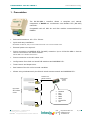
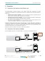
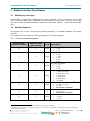
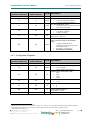
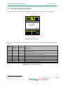
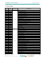
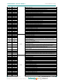
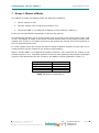
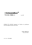
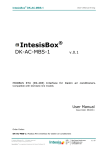
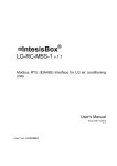
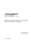
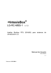
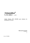
IntesisBox DK-RC-MBS-1 ® v.0.8 MODBUS RTU (RS-485) Interface for Daikin air conditioners. Compatible with VRV and commercialized by Daikin. SKY line air conditioners User Manual Issue Date: 2013/02/26 Order Code: DK-RC-MBS-1 IntesisBox® DK-RC-MBS-1 User’s Manual r2 eng © Intesis Software S.L. 2012. All Rights Reserved. Information in this document is subject to change without notice. No part of this publication may be reproduced, stored in a retrieval system or transmitted in any form or any means electronic or mechanical, including photocopying and recording for any purpose other than the purchaser’s personal use without the written permission of Intesis Software S.L. Intesis Software S.L. Milà i Fontanals, 1 bis 08700 Igualada Spain TRADEMARKS All trademarks and tradenames used in this document are acknowledged to be the copyright of their respective holders. © Intesis Software S.L. - All rights reserved This information is subject to change without notice ® IntesisBox is a registered trademark of Intesis Software SL URL Email tel http://www.intesis.com [email protected] +34 938047134 2 / 17 IntesisBox® DK-RC-MBS-1 User’s Manual r2 eng INDEX 1. Presentation .................................................................................................... 4 2. Connection ...................................................................................................... 5 2.1 Connection of the interface to the AC indoor unit ............................................... 5 2.2 Connection of the interface to Modbus ............................................................. 5 3. Modbus Interface Specification ........................................................................... 6 3.1 Modbus physical layer .................................................................................... 6 3.2 Modbus Registers .......................................................................................... 6 3.2.1 Control and status registers ...................................................................... 6 3.2.2 Configuration Registers ............................................................................ 7 3.2.3 Considerations on DK-RC-MBS-1 temperature registers ............................... 8 3.3 DIP-switch Configuration Interface .................................................................. 9 3.4 Implemented Functions ................................................................................ 11 3.5 Device LED indicator .................................................................................... 11 3.6 RS485 bus. Termination resistors and Fail Safe Biasing mechanism ................... 11 4. Specifications................................................................................................. 13 5. List of supported AC Unit Types. ....................................................................... 13 6. Error Codes ................................................................................................... 14 7. Annex 1: Master of Mode................................................................................. 17 © Intesis Software S.L. - All rights reserved This information is subject to change without notice ® IntesisBox is a registered trademark of Intesis Software SL URL Email tel http://www.intesis.com [email protected] +34 938047134 3 / 17 IntesisBox® DK-RC-MBS-1 User’s Manual r2 eng 1. Presentation The DK-RC-MBS-1 interface allows a complete and natural integration of Daikin air conditioners into Modbus RTU (RS-485) networks. Compatible with all SKY Air and VRV models commercialized by DAIKIN Reduced dimensions. 93 x 53 x 58 mm. Quick and easy installation. Mountable on DIN rail, wall, or even inside the indoor unit in some models of AC. External power not required. Direct connection to MODBUS RTU (RS-485) networks. Up to 63 DK-RC-MBS-1 devices can be connected in the same network. DK-RC-MBS-1 is a Modbus slave device. Direct connection to the AC indoor unit. Configuration from both on-board DIP-switches and MODBUS RTU. Total Control and Supervision. Real states of the AC unit's internal variables. Allows using simultaneously the IR and wired remote controls and MODBUS RTU. Modbus RTU RS485 network Modbus RTU master device DK-RC-MBS-1 Up to 63 AC indoor units DK-RC-MBS-1 SCADA PLC DDC BMS HMI Controller etc DK-RC-MBS-1 © Intesis Software S.L. - All rights reserved This information is subject to change without notice ® IntesisBox is a registered trademark of Intesis Software SL URL Email tel http://www.intesis.com [email protected] +34 938047134 4 / 17 IntesisBox® DK-RC-MBS-1 User’s Manual r2 eng 2. Connection 2.1 Connection of the interface to the AC indoor unit The DK-RC-MBS-1 connects directly to the Daikin P1/P2 Bus. Depending on which controllers are available the recommended connection methods are the following (details in Figure 2.1): Wired remote control available. Connect the gateway as Slave in parallel with the wired remote controllers (Wall controller acts as master). Infrared remote control available. Connect the gateway as Master in parallel with the infrared remote controller (Infrared receiver) as Slave. No remote control available Connect the gateway directly to the P1/P2 bus of the indoor unit as Master when there is no Daikin remote controller Disconnect mains power from the AC unit and use a 2 wire cable with a diameter of 0.75mm2 to 1.25mm2 for the connection of DK-RC-MBS-1, Daikin’s remote controller and its corresponding indoor unit. Screw the suitably peeled cable ends in the corresponding P1/P2 terminals of each device, as summarized in Figure 2.1. Maximum P1/P2 bus length is 500 meter, cable has no polarity. 2.2 Connection of the interface to Modbus Use the EIA485 connector in the DK-RC-MBS-1 to connect to the Modbus network. 53 mm Remote Control For wall mount extract the upper and lower staples until you hear the "click". DAIKIN AC Indoor Unit P1 P2 AC Unit IntesisBox® DK-RC-MBS-1 Internal electronic control board EIA485 P1 P2 A+ B- 90 mm P1 P2 MODBUS RTU EIA485 Bus Max. 500 m 53 mm Connection to P1 P2 bus. Two wires cable. AC Indoor Unit P1 P2 AC Unit IntesisBox® DK-RC-MBS-1 EIA485 Internal electronic control board A+ B- P1 P2 MODBUS RTU EIA485 Bus Max. 500 m Figure 2.1 DK-RC-MBS-1 Connection diagrams © Intesis Software S.L. - All rights reserved This information is subject to change without notice ® IntesisBox is a registered trademark of Intesis Software SL URL Email tel http://www.intesis.com [email protected] +34 938047134 5 / 17 IntesisBox® DK-RC-MBS-1 User’s Manual r2 eng 3. Modbus Interface Specification 3.1 Modbus physical layer DK-RC-MBS-1 implements a MODBUS RTU (slave) interface, to be connected to an RS-485 line. It performs 8N2 (8N1-compatible) communication (8 data bits, no parity and 2 stop bit) with several available baudrates (2400 bps, 9600 bps -default-, 19200 bps and 57600 bps). 3.2 Modbus Registers All registers are of type “16-bit signed Holding Register”, in standard ModBus’ big endian notation. The registers are accessible as “Holding registers” or “Input Registers” 3.2.1 Control and status registers Register Addr (protocol address) Register Addr (PLC address) R/W 0 1 R/W Description AC unit On/Off 0: Off 1: On AC unit Mode1 1 2 R/W 0: 1: 2: 3: 4: Auto Heat Dry Fan Cool AC unit Fan Speed1 2 3 R/W 1: Low 2: Mid 3: High AC unit Vane Position1 3 4 R/W 1: POS1 (Horizontal) 2: POS2 (Horizontal) 3: POS3 (Med) 4: POS4 (Vert) 5: POS5 (Vert) 10: SWING AC unit Temperature Setpoint2,3 4 1 2 3 5 R/W 5 6 R 6 7 R/W 16..32ºC (ºC/x10ºC) 60..90ºF See section 3.2.3 below. AC unit Return Path Temperature2, 3 (ºC/x10ºC/F)2 See section 3.2.3 below. Window Contact 0: Closed 1: Open See Section 5 for detail on indoor unit model differences and function availability Magnitude for this register can be adjusted to Celsius x 1ºC, Celsius x 10ºC (default) or Fahrenheit through DIP switches S4 Check Table 3.4 for details © Intesis Software S.L. - All rights reserved This information is subject to change without notice ® IntesisBox is a registered trademark of Intesis Software SL URL Email tel http://www.intesis.com [email protected] +34 938047134 6 / 17 IntesisBox® DK-RC-MBS-1 7 Register Addr (PLC address) 8 8 9 Register Addr (protocol address) User’s Manual r2 eng R/W -R/W 9 10 R/W 10 11 R 11 12 R Description Reserved Remote Command Disablement3 0: Remote Command enabled 1: Remote Command disabled AC unit Operation Time4 0..65535 (hours). Counts the time the AC unit is in “On” state. AC unit Alarm Status 0: No alarm condition 1: Alarm condition Error Code Information in section 6 Indoor unit ambient temperature from external sensor (at Modbus side) 22 23 R/W -32768: Default value. No temperature is being provided from an external sensor. Any other: (ºC/x10ºC/ºF)5 See section 3.2.3 below. 3.2.2 Configuration Registers 12 Register Addr (PLC address) 13 13 14 Register Addr (protocol address) R/W Description R/W Reserved “Open Window” switch-off timeout6,4 R/W 0..30 (minutes) Factory setting: 30 (minutes) Modbus RTU baud-rate (bps) 4 5 6 7 14 15 R 15 16 R 21 22 R 49 50 R 50 51 R 2400 4800 9600 19200 Device's Modbus slave address 1..63 Max number of fan speeds7 2 3 Device Identification DK-RC-MBS-1: 0x800 Software version This value is stored in non-volatile memory Magnitude for this register can be adjusted to Celsius x 1ºC, Celsius x 10ºC (default) or Fahrenheit through DIP switches S4 Once window contact is open, a count-down to switch off the AC Unit will start from this configured value Configured with S1 (Table 3.1) © Intesis Software S.L. - All rights reserved This information is subject to change without notice ® IntesisBox is a registered trademark of Intesis Software SL URL Email tel http://www.intesis.com [email protected] +34 938047134 7 / 17 IntesisBox® DK-RC-MBS-1 User’s Manual r2 eng 3.2.3 Considerations on DK-RC-MBS-1 temperature registers DK-RC-MBS-1 implements three registers containing temperature values: AC unit Temperature Setpoint (R/W) (register 5 – in PLC addressing): This is the adjustable temperature setpoint meant to be required by the user. This register can be read (Modbus function 3 or 4) or written (Modbus functions 5 or 16). A remote controller connected to the P1P2 bus of the Daikin indoor unit will report the same temperature setpoint value as this register. AC unit return path temperature (R) (register 6 – in PLC addressing): This register always shows the temperature reported by the sensor placed in the return path temperature of the Daikin indoor unit. It is a read-only register (Modbus functions 3 or 4). AC unit external reference temperature (R/W) (register 23 – in PLC addressing): This register allows providing an external temperature reference from Modbus side. If an external temperature is provided through this register, indoor unit will use it as reference for its temperature control loop. o o o o For this temperature to take effect it is required that the Daikin AC indoor unit is configured in such a way that it uses the “thermostat sensor in the remote controller” (this is, DK-RC-MBS-1 will act as thermostat sensor providing a temperature sensor reading). This configuration is done via a Daikin remote controller connected to the indoor unit (Config mode “10” – first code value “2” – second code value “1”) and must be done by Daikin authorized installers at the time of the installation of the AC. The value of this register only takes effect when DK-RC-MBS-1 is set as “master” of P1P2 bus, with respect to an additional remote controller in the bus (see section “2.1 - Connection of the interface to the AC indoor unit” and “3.3 - DIP-switch Configuration Interface”) Register value after DK-RC-MBS-1 startup is -32768, which means that no temperature reference is provided to the AC indoor unit. In that case, AC indoor unit will use its own return path temperature sensor as reference for its control loop. Additionally, note that temperature values all these three registers are expressed according to the temperature format configured through its onboard DIP-Switches (See “3.3 - DIP-switch Configuration Interface”). Following formats are possible: Celsius value: Value in Modbus register is the temperature value in Celsius (i.e. a value “22” in the Modbus register must be interpreted as 22ºC) Decicelsius value: Value in Modbus register is the temperature value in decicelsius (i.e. a value “220” in the Modbus register must be interpreted as 22.0ºC) Fahrenheit value: Value in Modbus register is the temperature value in Fahrenheit (i.e. a value “72” in the Modbus register must be interpreted as 72ºF (~22ºC). © Intesis Software S.L. - All rights reserved This information is subject to change without notice ® IntesisBox is a registered trademark of Intesis Software SL URL Email tel http://www.intesis.com [email protected] +34 938047134 8 / 17 IntesisBox® DK-RC-MBS-1 3.3 User’s Manual r2 eng DIP-switch Configuration Interface In this section the values of the configuration switches and their meaning are specified: L1 L2 S1 ON 1 2 3 4 P1 P2 AC Unit IntesisBox® DK-RC-MBS-1 EIA485 A+ B- ON 1 2 3 4 5 6 7 8 ON 1 2 3 4 S3 S4 Figure 3.1 DK-RC-MBS S1 – AC unit configuration: Master/Slave, Master/Slave of Operating Mode, Fan speeds and Vanes Binary value b0…b4 Decimal value Switches 1 2 3 4 Description 0xxx 0 x x x Slave– A Daikin BRC Controller must be present in P1 P2, configured as Master (default value). 1xxx 1 x x x Master in P1 P2 bus – Daikin BRC Controller not needed in P1 P2. If existing, BRC must be configured as slave x0xx 0 x x x Master of VRV Operation Mode (For VRV only)8 x1xx 1 x x x VRV slave of Operating Mode (For VRV only) (default value) xx0x 0 xx1x 1 x x x x x x Indoor unit has 2 Fan Speeds (default value) Indoor unit has 3 fan speeds xxx0 0 x x x Indoor unit has no Vanes xxx1 1 x x x Indoor unit has Vanes (default value) Table 3.1 S1 switch configuration 8 Explained in section 7 © Intesis Software S.L. - All rights reserved This information is subject to change without notice ® IntesisBox is a registered trademark of Intesis Software SL URL Email tel http://www.intesis.com [email protected] +34 938047134 9 / 17 IntesisBox® DK-RC-MBS-1 User’s Manual r2 eng S3 – Modbus protocol: Slave address and baudrate Add Switches 1 2 3 4 5 6 7 8 Add Switches 1 2 3 4 5 6 7 8 Add Switches 1 2 3 4 5 6 7 8 Add Switches 1 2 3 4 5 6 7 8 0 x x 16 x x 32 x x 48 x x 1* x x 17 x x 33 x x 49 x x 2 x x 18 x x 34 x x 50 x x 3 x x 19 x x 35 x x 51 x x 4 x x 20 x x 36 x x 52 x x 5 x x 21 x x 37 x x 53 x x 6 x x 22 x x 38 x x 54 x x 7 x x 23 x x 39 x x 55 x x 8 x x 24 x x 40 x x 56 x x 9 x x 25 x x 41 x x 57 x x 10 x x 26 x x 42 x x 58 x x 11 x x 27 x x 43 x x 59 x x 12 x x 28 x x 44 x x 60 x x 13 x x 29 x x 45 x x 61 x x 14 x x 30 x x 46 x x 62 x x 15 x x 31 x x 47 x x 63 x x Table 3.2 S3 Modbus Slave address Binary value b0…b8 Decimal value Switches 1 2 3 4 5 6 7 8 xxxxxx00 0 x x x x x x 2400bps xxxxxx10 1 x x x x x x 4800bps xxxxxx01 2 x x x x x x 9600bps (default value) xxxxxx11 3 x x x x x x 19200bps Description Table 3.3 S3 Modbus baud rate S4 – Other: Degrees/Decidegress (x10), temperature magnitude (ºC/ºF) and EIA485 termination resistor Binary value b0…b4 Decimal value Switches 1 2 3 4 Description 0xxx 0 x x x Temperature values in Modbus register are represented in degrees (x1) (default value) 1xxx 1 x x x Temperature values in Modbus register are represented in decidegrees (x10) x0xx 0 x x x Temperature values in Modbus register are represented in Celsius degrees (default value) x1xx 1 x x x Temperature values in Modbus register are represented in Fahrenheit degrees (value for S4-1 (x1/x10) is ignored) xxx0 0 x x x EIA485 bus without termination resistor (default value) xxx1 1 x x x Internal termination resistor of 120Ω connected to EIA485 bus** Table 3.4 S4: Temperature and termination configuration * Default value Only in the interfaces connected at both ends of the bus must be activated the termination resistor, not in the rest. ** © Intesis Software S.L. - All rights reserved This information is subject to change without notice ® IntesisBox is a registered trademark of Intesis Software SL URL Email tel http://www.intesis.com [email protected] +34 938047134 10 / 17 IntesisBox® DK-RC-MBS-1 3.4 User’s Manual r2 eng Implemented Functions DK-RC-MBS-1 implements the following standard MODBUS functions: 3: Read Holding Registers 4: Read Input Registers 6: Write Single Register 16: Write Multiple Registers (Although this function is allowed, the interface does not allow write operations on more than 1 register with the same request, this means that length field should always be 1 when using this function for writes) 3.5 Device LED indicator The device includes two LED indicators (check Figure 3.1) to signal its different possible operational states. In this section their meaning is explained L1 (yellow) Operation Blinking Flashing L2 (red) Operation Pulse ON 500 ms 100 ms OFF 500 ms 1900 ms ON 3 sec OFF -- L1 (yellow) & L2 (red) Operation ON Pulse 5 sec Alternate blinking 500 ms 3.6 OFF -500 ms Meaning Communication error Normal operation (configured and working) Meaning Undervoltage Meaning Device start-up Flash checksum not OK RS485 bus. Termination resistors and Fail Safe Biasing mechanism RS485 bus requires a 120Ω terminator resistor at each end of the bus to avoid signal reflections. The DK-RC-MBS-1 device includes an on-board terminator resistor of 120Ω that can be connected to the RS485 bus by using DIP-switch (Table 3.4) A fail safe biasing circuit has also been included in the board of DK-RC-MBS-1, it can be connected to the RS485 bus by placing the internal jumper JP1(see details in Figure 3.2). This fail safe biasing of the RS485 bus must only be supplied by one of the devices connected to the bus Some Modbus RTU RS485 master devices can provide also internal 120Ω terminator resistor and/or fail safe biasing (consult the technical documentation of the master device connected to the RS485 network in every case). © Intesis Software S.L. - All rights reserved This information is subject to change without notice ® IntesisBox is a registered trademark of Intesis Software SL URL Email tel http://www.intesis.com [email protected] +34 938047134 11 / 17 IntesisBox® DK-RC-MBS-1 User’s Manual r2 eng Location of jumpers and DIP-switches for RS485 bus Termination resistor or Fail Safe Biasing selection: ON 1 2 3 4 Jumpers placed Fail safe biasing circuit connected to the RS485 bus JP1 1 JP2: ON (jumper placed) ON 1 2 3 4 5 6 7 8 ON 1 2 3 4 Figure 3.2 Fail Safe jumper ON 1 2 3 4 To access to internal jumpers JP2 and JP3, extract the top cover of the interface inserting a small screw-driver or clip in the holes located at both sides of the cover. P1 P2 AC Unit IntesisBox® DK-RC-MBS-1 EIA485 A+ BON 1 2 3 4 5 6 7 8 ON 1 2 3 4 Figure 3.3 Accessing the jumpers © Intesis Software S.L. - All rights reserved This information is subject to change without notice ® IntesisBox is a registered trademark of Intesis Software SL URL Email tel http://www.intesis.com [email protected] +34 938047134 12 / 17 IntesisBox® DK-RC-MBS-1 User’s Manual r2 eng 4. Specifications Dimensions: Weight: Operating Temperature: Stock Temperature: Operating Humidity: Stock Humidity: Isolation voltage: Isolation resistance: Modbus Media: 93 x 53 x 58 mm 85 g -40 . . . 85ºC -40 . . . 85ºC <95% RH, non-condensing <95% RH, non-condensing 1000 VDC 1000 MΩ Compatible with Modbus RTU - RS485 networks AC Unit connection LED Indicator DIP Switches DIP Switches 58 mm RS485 Port 53 mm 93 mm 5. List of supported AC Unit Types. A list of Daikin indoor unit model references compatible with DK-RC-MBS-1 and their available features can be found in: http://www.intesis.com/pdf/IntesisBox_DK-RC-xxx-1_AC_Compatibility.pdf © Intesis Software S.L. - All rights reserved This information is subject to change without notice ® IntesisBox is a registered trademark of Intesis Software SL URL Email tel http://www.intesis.com [email protected] +34 938047134 13 / 17 IntesisBox® DK-RC-MBS-1 User’s Manual r2 eng 6. Error Codes Error Code Modbus 0 17 18 19 20 21 22 23 24 25 26 27 28 30 31 32 33 36 37 38 39 40 41 42 43 44 45 46 47 48 49 50 52 53 54 55 56 57 58 59 60 61 62 63 64 65 66 67 68 69 70 71 72 73 74 75 76 77 79 80 81 82 83 84 87 91 92 93 95 96 97 Error in Remote Controller N/A A0 A1 A2 A3 A4 A5 A6 A7 A8 A9 AA AH AJ AE AF C0 C3 C4 C5 C6 C7 C8 C9 CA CH CC CJ CE CF E0 E1 E3 E4 E5 E6 E7 E8 E9 EA EH EC EJ EE EF H0 H1 H2 H3 H4 H5 H6 H7 H8 H9 HA HH HC HE HF F0 F1 F2 F3 F6 FA FH FC FE FF J0 Error category Indoor Unit Outdoor Unit Error Description No active error External protection devices activated Indoor unit PCB assembly failure Interlock error for fan Drain level system error Temperature of heat exchanger (1) error Temperature of heat exchanger (2) error Fan motor locked, overload, over current Swing flap motor error Overcurrent of AC input Electronic expansion valve drive error Heater overheat Dust collector error / No-maintenance filter error Capacity setting error (indoor) Shortage of water supply Malfunctions of a humidifier system (water leaking) Malfunctions in a sensor system Sensor system of drain water error Heat exchanger (1) (Liquid pipe) thermistor system error Heat exchanger (1) (Gas pipe) thermistor system error Sensor system error of fan motor locked, overload Sensor system of swing flag motor error Sensor system of over-current of AC input Suction air thermistor error Discharge air thermistor system error Contamination sensor error Humidity sensor error Remote control thermistor error Radiation sensor error High pressure switch sensor Protection devices activated Outdoor uni9t PCB assembly failure High pressure switch (HPS) activated Low pressure switch (LPS) activated Overload of inverter compressor motor Over current of STD compressor motor Overload of fan motor / Over current of fan motor Over current of AC input Electronic expansion valve drive error Four-way valve error Pump motor over current Water temperature abnormal (Site installed) Protection device activated Malfunctions in a drain water Ice thermal storage unit error Malfunctions in a sensor system Air temperature thermistor error Sensor system of power supply error High Pressure switch is faulty Low pressure switch is faulty Compressor motor overload sensor is abnormal Compressor motor over current sensor is abnormal Overload or over current sensor of fan motor is abnormal Sensor system of over-current of AC input Outdoor air thermistor system error Discharge air thermistor system error Pump motor sensor system of over current is abnormal Water temperature sensor system error Sensor system of drain water is abnormal Ice thermal storage unit error (alarm) No.1 and No.2 common protection device operates. No.1 protection device operates. No.2 protection device operates Discharge pipe temperature is abnormal Temperature of heat exchanger(1) abnormal Discharge pressure abnormal Oil temperature is abnormally high Suction pressure abnormal Oil pressure abnormal Oil level abnormal Sensor system error of refrigerant temperature © Intesis Software S.L. - All rights reserved This information is subject to change without notice ® IntesisBox is a registered trademark of Intesis Software SL URL Email tel http://www.intesis.com [email protected] +34 938047134 14 / 17 IntesisBox® DK-RC-MBS-1 User’s Manual r2 eng 98 99 100 101 102 103 104 105 106 107 108 109 111 112 113 116 117 118 119 120 121 122 123 125 129 130 132 133 134 135 136 142 145 146 147 148 J1 J2 J3 J4 J5 J6 J7 J8 J9 JA JH JC JE JF L0 L3 L4 L5 L6 L7 L8 L9 LA LC P0 P1 P3 P4 P5 P6 P7 PJ U0 U1 U2 U3 Pressure sensor error Current sensor error Discharge pipe thermistor system error Low pressure equivalent saturated temperature sensor system error Suction pipe thermistor system error Heat exchanger(1) thermistor system error Heat exchanger(2) thermistor system error Oil equalizer pipe or liquid pipe thermistor system error Double tube heat exchanger outlet or gas pipe thermistor system error Discharge pipe pressure sensor error Oil temperature sensor error Suction pipe pressure sensor error Oil pressure sensor error Oil level sensor error Inverter system error Temperature rise in a switch box Radiation fin (power transistor) temperature is too high Compressor motor grounded or short circuit, inverter PCB fault Compressor motor grounded or short circuit, inverter PCB fault Over current of all inputs Compressor over current, compressor motor wire cut Stall prevention error (start-up error) Compressor locked, etc. Power transistor error Communication error between inverter and outdoor control unit Shortage of refrigerant (thermal storage unit) Power voltage imbalance, open phase Sensor error of temperature rise in a switch box Radiation fin temperature sensor error DC current sensor system error AC or DC output current sensor system error Total input current sensor error Capacity setting error (outdoor) Low pressure drop due to insufficient refrigerant or electronic expansion valve error, etc. Reverse phase, Open phase Power voltage failure / Instantaneous power failure Failure to carry out check operation, transmission error 149 U4 150 U5 151 U6 152 U7 153 U8 154 U9 155 UA 156 UH 157 158 159 UC UJ UE 160 UF 209 210 211 212 213 214 217 219 220 221 222 223 224 226 227 228 229 241 242 243 244 245 258 259 60 61 62 63 64 65 68 6A 6H 6C 6J 6E 6F 51 52 53 54 40 41 42 43 44 31 32 Communication error between indoor unit and outdoor unit, communication error between outdoor unit and BS unit Communication error between remote control and indoor unit / Remote control board failure or setting error for remote control Communication error between indoor units Communication error between outdoor units / Communication error between outdoor unit and ice thermal storage unit Communication error between main and sub remote controllers (sub remote control error) / Combination error of other indoor unit / remote control in the same system (model) Communication error between other indoor unit and outdoor unit in the same system / Communication error between other BS unit and indoor/outdoor unit Combination error of indoor/BS/outdoor unit (model, quantity, etc.), setting error of spare parts PCB when replaced Improper connection of transmission wiring between outdoor and outdoor unit outside control adaptor Centralized address duplicated Attached equipment transmission error Communication error between indoor unit and centralized control device Failure to carrey out check operation Indoor-outdoor, outdoor-outdoor communication error, etc. All system error PC board error Ozone density abnormal Contamination sensor error Indoor air thermistor system error Outdoor air thermistor system error HVU error (Ventiair dust-collecting unit) Dumper system error Door switch error Replace the humidity element Replace the high efficiency filter Replace the deodorization catalyst Simplified remote controller error Fan motor of supply air over current or overload Fan motor of return air over current / Fan motor of return air overload Inverter system error (supply air side) Inverter system error (return air side) Humidifying valve error Chilled water valve error Hot water valve error Heat exchanger of chilled water error Heat exchanger of hot water error The humidity sensor of return air sensor Outdoor air humidity sensor error System Others © Intesis Software S.L. - All rights reserved This information is subject to change without notice ® IntesisBox is a registered trademark of Intesis Software SL URL Email tel http://www.intesis.com [email protected] +34 938047134 15 / 17 IntesisBox® DK-RC-MBS-1 260 261 262 263 267 268 269 339 345 347 349 65535 33 34 35 36 3A 3H 3C M2 M8 MA MC N/A DK-RC-MBS-1 User’s Manual r2 eng Supply air temperature sensor error Return air temperature sensor error Outdoor air temperature sensor error Remote controller temperature sensor error Water leakage sensor 1 error Water leakage sensor 2 error Dew condensation error Centralized remote controller PCB error Communication error between centralized remote control devices Centralized remote control devices inappropriate combination Centralized remote controller address setting error Error in the communication of DK-RC-MBS-1 device with the AC unit In case you detect an error code not listed, contact your nearest Daikin technical support service. © Intesis Software S.L. - All rights reserved This information is subject to change without notice ® IntesisBox is a registered trademark of Intesis Software SL URL Email tel http://www.intesis.com [email protected] +34 938047134 16 / 17 IntesisBox® DK-RC-MBS-1 User’s Manual r2 eng 7. Annex 1: Master of Mode The master of mode only applies under the following conditions: 1. The AC system is VRV 2. The VRV system uses a Heat pump outdoor unit 3. The DK-RC-MBS-1 is configured as Master of the P1/P2 bus (Table 3.1) If they are not matched the parameter is going to be ignored. The Heat pump outdoor unit of a VRV system can only work in one mode (either Heat, Cool or fan). The Master of mode is the indoor unit that defines which is the working mode of the outdoor unit. If there is no Master of mode in the system the first AC unit to be turned On is the one controlling the mode. In a VRV system there can only be one device acting as Master of Mode. If more than one is configured this way the system is not going to work properly. When a DK-RC-MBS-1 is configured as Master of Mode it can control all the modes of the system (section 3.2.1). The Mode selection of all the other gateways and remote controllers is going to be affected by the one chosen by the Master of Mode (detailed in Table 7.1) Master of Mode Heat Dry Fan Cool Slave of Mode Heat, Fan Cool, Fan, Dry Fan Cool, Fan, Dry Table 7.1 Mode correspondence © Intesis Software S.L. - All rights reserved This information is subject to change without notice ® IntesisBox is a registered trademark of Intesis Software SL URL Email tel http://www.intesis.com [email protected] +34 938047134 17 / 17