1
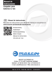
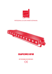
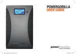
User Manual WEB
Charger for
Li-Ion Batteries
EN
User Manual
Language specific user manuals are available on
www.mascot.no/downloads/usermanuals
Bruksanvisning
Käyttöohjeet
Bedienungsanleitung
Mode d’emploi
Manual de instrucciones
Istruzioni per l’uso
MASCOT ELECTRONICS AS
P.O.Box 177, N-1601 Fredrikstad, NORWAY
Phone: +47 69 36 43 00 • Telefax: +47 69 36 43 01
E-mail: [email protected] • Web: www.mascot.no
Doc.no. 5170 - Part No. 205170 - 30.04.2015
IMPORTANT SAFETY INSTRUCTIONS!
TO REDUCE THE RISK OF FIRE AND ELECTRIC SHOCK:
READ THROUGH THESE INSTRUCTIONS PRIOR TO USING THE PRODUCT.
CAREFULLY FOLLOW THESE INSTRUCTIONS WHEN USING THE PRODUCT.
RETAIN THESE INSTRUCTIONS FOR FUTURE REFERENCE.
ding to standard EN/IEC 60529, but must not be
immersed in water for longer periods of time.
CAUTION! DOUBLE POLE / NEUTRAL FUSING!
Products marked with the “double square symbol”
are double insulated (Insulation Class II). Products
without this mark are Class I (relies on safety earth
for protection).
WARNING: To avoid risk of electric shock, Class
I products must only be connected to a supply
mains with protective earth.
This product is designed for indoor use.
(Not applicable to products marked ”IP67”)
IP41
IP44
IP67
A version of this product marked ”IP41” may be
available. This version is protected against ingress
of solid objects larger than 1.0 mm and the effects
of vertically falling drops of water according to
standard EN/IEC 60529.
At the end of their service life electric and
electronic equipment and their accessories shall
not be discarded with the municipal waste but be
disposed of using separate collection, treatment,
recovery/recycling and environmentally sound
disposal. This also applies to any potentially bio
hazardous parts and accessories. If in doubt;
contact your local authorities to determine the
proper method.
A version of this product marked ”IP44” may be
available. This version is protected against ingress
of solid objects larger than 1.0 mm and the effects
of water splashed against the enclosure from any
direction according to standard EN/IEC 60529.
A version of this product, marked with a symbol
with two drops of water and/or ”IP67”, may be
available. This version is filled with a potting
compound and is dust-tight and protected against
the effects of temporary immersion in water accor-
Technical specifications for your product:
See tables, the marking on the
product or www.mascot.no
2
Cautions to observe prior to use
• The intended use for this product is to charge a
battery or a battery powered electrical accessory
(NiCd/NiMH, Lead-Acid, Lithium-Ion or LiFePO4
batteries) or to be used as a Power Supply to
power an electrical accessory. Please see the
marking on the product you have to verify the
type of product you have and read the applicable
instructions and technical specifications included with this manual.
• The product is “switched on” by inserting the
mains plug into the mains socket and “switched
off” by disconnecting the mains plug from the
mains socket.
• The product may be connected to an IT type
mains supply.
• For use in U.S.A.:
- Be sure to use 125V 15A receptacle configuration before plugging in.
- Use a UL817-standard compliant mains cord
(plug type NEMA 1-15, cord type SJT or SVT).
• This product may be used by unskilled operators, under the condition that these instructions
are followed.
• For use outside U.S.A:
Use a mains cord compliant with the country
specific requirements.
• Unskilled operators may contact the supplier
or manufacturer for assistance, if needed, in
setting up, using or maintaining this product and
to report unexpected operation or events.
• The time from powering this product until its full
function starts may exceed 15 seconds.
• This appliance can be used by children aged
from 8 years and above and persons with
reduced physical, sensory or mental capabilities
or lack of experience and knowledge if they have
been given supervision or instruction concerning
use of the appliance in a safe way and understand the hazards involved. Children shall not
play with the appliance.
• Should an operational error or unexpected
change in the performance occur during use;
disconnect the product from the mains immediately by disconnecting the mains plug from the
mains socket and contact the supplier
• When not in use please think about disconnecting the product from the mains. This will
reduce the risk of hazards, reduce the products
environmental impact and save electricity costs.
• Do not allow animals to come into contact
with this product. Some animals are known to
cause damage to cables etc which may be a
potential for risk of electric shock and excessive
temperatures. Also, cables and small parts may
represent a strangulation risk for the animal.
• To avoid overheating make sure there is sufficient room for the circulation of air around the
product when in use. Do not cover it up.
• Even though this product complies with relevant
safety standards it should not be in contact with
human skin for long periods as some people
may get allergies or injuries from long-term
contact with moderate temperatures and/or
plastic materials.
• If the product is equipped with a mains cord,
please check that the cord is not damaged. If
the cord is damaged, the product must not be
used until the cord is replaced. Replacement
should be carried out by qualified personnel.
• Prior to using this product with accessories and/
or interconnected equipment please carefully
read its respective User Manuals.
• The mains socket outlet used should always be
easily accessible to facilitate immediate removal
of the products mains supply should an operational error occur during use. If the product has a
detachable mains cord the appliance coupler may
be used as a disconnect device.
• If the product is supplied with exchangeable
output plugs, please see separate page for
assembly.
3
• Output cables having a modular plug ( similar to
a telephone connector) must never be connected to a telephone outlet.
nently wired to the building installation:
Installation must only be carried out by qualified
service personnel, following the below instructions:
- The protective earth conductor must be min.
0.75 mm2.
- Connect the protective earth conductor to the
external protective earthing system.
- Verify that the protective earth terminal used is
connected to the external protective earthing
system.
- Verify the integrity of the external protective
earthing system.
• Products with a welded plastic housing are
not repairable. Please contact your supplier for
replacement part.
• This product contains hazardous voltages and
there are no user replaceable parts inside the
product. Never attempt to remove the cover.
• WARNING: No modification of this equipment is
allowed. Any repair/service should be carried out
by qualified personnel who may get assistance
by contacting the manufacturer or the manufacturer’s agent.
• This product converts the mains voltage to
a safety extra low voltage.
Some products may be treated as Applied
Part (Type BF) according to standard EN/IEC
60601-1 and may come in physical contact with
a patient.
• Products specified to have automatic polarity
protection must be switched off if a battery is
connected with reverse polarity. The protection
will be automatically reset when the polarity has
been corrected.
• This product must be operated in an environment within temperature range +5 to +40°C,
humidity 15 - 93 % RH and atmospheric pressure 70 - 106 kPa (700 - 1060 hPa).
• In chargers specified to have a replaceable fuse
as polarity protection the fuse must be replaced
if the battery has been connected with reverse
polarity. When replacing the fuse; a fuse of the
same type and rating must be used.
• Expected service life of this product and accessories delivered with this product is three (3)
years, if operated as indicated above. However;
the guarantee times indicated in document
”TERMS OF SALES AND DELIVERY FOR MASCOT AS” apply (available at www.mascot.com).
• If the product is specified to comply with the
standard for Medical Electrical Equipment (standards based on IEC60601-1) it complies with
some of the requirements for medical electrical
equipment and may be used in medical applications and hospital environments.
• Environmental parameters during transport and
storage between uses: temperature range -25 to
+85 °C, humidity 15 - 93% RH NC and atmospheric pressure 70 - 106 kPa (700 - 1060 hPa).
• The product must not be used in the vicinity of
flammable anesthetic gases or in other environments with flammable or explosive atmosphere.
• If stored for longer periods of time the
environmental parameters should be within
the temperature range +5 to +35°C, humidity
range 10 - 75% RH NC and atmospheric pressure 70 - 106 kPa (700 - 1060 hPa) to maintain
the products expected service life.
• If the product is specified to comply with the
standard for Medical Electrical Equipment
for Home Healthcare Environment (standard
IEC60601-1-11) it may be used in medical
applications used in a home healthcare environment.
• Expected shelf life of this product is one (1) year,
if stored as indicated above.
• This product complies with the requirements to
electromagnetic compatibility for medical electric equipment and for use in residential, office
NOTE: Products relying on safety earth for
protection (Class I) may not be used in home
healthcare environment unless they are perma4
or light industrial environment but all electric
products imply a potential for electromagnetic
or other interference between the product and
other devices. If such interference is suspected
please disconnect the product from the mains
and consult a qualified technician, your supplier
or the manufacturer.
degraded by such chemicals. Also make sure to
position, operate and store such products away
from UV-light and direct sunlight.
• Position, operate and store this product only
under reasonable foreseeable environmental
conditions with respect to magnetic fields,
EM-fields, electrostatic discharges, pressure or
variations in pressure, acceleration etc.
• No special maintenance procedure is required
but if the product gets dusty or dirty it should be
wiped clean using a dry cloth while the product
is disconnected from the mains. No other maintenance should be necessary.
• If this product is used with or mounted in a
vehicle it may only be used when the vehicle is
not in use.
• For products having a plastic casing, please
avoid any contact with lotions, oils, grease
and solvents as most types of plastic may be
• When in use, position this product so that the label can be read – within 40 cm of the operator.
Cautions to observe prior to charging Li-Ion-batteries
• Li-Ion chargers are designed for charging Li-Ion
(LI) batteries only. Make sure you have the
correct battery charger for the chemistry and
number of cells in series. If the number of cells
in series in the battery pack is not known you
can calculate it by dividing the voltage indicated
by 3.6VDC for LI (e.g. a 14.4VDC LI battery
contains 4 Li-Ion cells).
Make sure the charge voltage indicated on the
charger corresponds to the number of battery
cells in series multiplied by 4.2VDC (e.g. a 4 cell
LI battery is typically charged using 16.8VDC).
• We recommend that you connect the charger to
the mains before connection is made to the battery. This will reduce the sparks that may occur
due to difference in potential between charger
terminals and battery terminals. Note! Make sure
the charger terminals are not short-circuited and
ensure that the polarity is correct.
• Please ensure correct polarity when connecting
to the battery terminals. Reverse polarity connection may, in some chargers (see the chargers
specifications), result in a fuse blowing, requiring
replacement or leaving the charger useless.
NOTE: The voltages indicated above are typical
and may vary between battery types and battery
makes. If in doubt; consult the specifications for
your battery.
• The charge cycle starts when the charger is
connected to the mains.
• If the charger is disconnected from the mains
voltage during a charge cycle the charger will
start a new charge cycle when it is reconnected
to the mains.
• Make sure the specifications for your battery allows for the maximum charge current indicated
on the charger.
• The recommended minimum and maximum
battery capacity for which the specific charger
can be used vary from battery to battery. Please
follow the datasheet and recommendations from
the battery manufacturer. In our tables we use
typical 1C as a maximum current for Li-Ion cells.
• Make sure the specifications for your battery
allows for the environmental conditions present
during charging.
• Never attempt to charge batteries that are not
rechargeable.
5
1C means that charge current for a 1Ah battery
should be max 1A. Thus the typical minimum
capacity recommendation is 1Ah for a 1A
charger. For max battery capacity we have used
C/40 for chargers with timer (and/or uC) and
100 times current detection levels for chargers
using only this termination method. For a 1A
charger with 0.1A current detection level the
max capacity recommended will be 100 x 0.1A
= 10Ah. Again this is just typical recommendations. Please read recommendations and
datasheets from battery manufacturer.
How to connect exchangeable
DC-output plugs
1. To connect for desired polarity, both plug ends
are clearly marked.
3
3
2. When connected, the female plug is also
marked on each side to identify plug polarity.
12
1 2
3. Shows the center polarity of the plug.
How to connect exchangeable AC-plugs
The following exchangeable AC plugs are available:
Type 018110 - ”EURO”
250V 2.5A (EN50075/IEC83 C5 II)
Type 018111 - ”US”
125V 2.5A
(NEMA 1-15 / CSA-C22.2 No.42)
Type 018112 - ”UK”
250V 13A (BS 1363)
Type 018114 - ”AUS”
250V 10A (AS/NZS 3112)
Mains Cord Set is available on request if you wish your product to be ”DeskTop”
6
Explanation of Li-Ion battery charge cycle
(See tables for methods for each charger model.)
Charging method A
STEP 1 – CONSTANT CURRENT CHARGE
To start a charge cycle; connect the charger to the mains.
The charger is in constant current mode, charging with the maximum current indicated on
the charger, the LED-indication on the charger is ORANGE. This step allows rapid charging
of your battery until the battery reaches typically 80 - 95% of its capacity.
Orange
Orange
STEP 2 – CONSTANT VOLTAGE CHARGE
The charger is in constant voltage mode, charging with a decreasing current until the current
is below the chargers charge termination level (indicated on the charger). The LED-indication
on the charger is ORANGE. The battery is charged to its full capacity at the end of this step
Orange
STEP 3 –CHARGE COMPLETE
The LED-indication on the charger is GREEN and the battery is fully charged.
For Li-Ion batteries the charge current is zero and the battery has been charged it its full
capacity. After end of charge battery voltage will remain at “Step 2” level even if output voltage
of charger is indicated as lower in the diagram. The charger will return to Step 1 if the battery
is used. A load larger than the cut-off current will initiate a new charge cycle.
Orange
Orange
Orange
Green
Green
Yellow
Green
Yellow
Yellow
Yellow
Yellow
Diagram: A
Yellow
INDICATOR: ORANGE
INDICATOR: GREEN
Charge Voltage
Charge Voltage
Charge Current
Cut-Off Current
Step 1
CC Charge
Step 2
CV Charge
7
Li-Ion diagrammer
Step 3
Charge complete
Diagram: A
Charging method B
INDICATOR: ORANGE
INDICATOR: GREEN
Orange
STEP 1 - CONSTANT CURRENT CHARGE
To start a charge cycle; connect the charger to the mains.
Orange
Voltage
The charger is in constant current mode, Charge
charging with
the maximum current indicated on
Charge
Voltage
the charger, the LED-indication on the charger is ORANGE. This step allows
rapid charging
Orange
Orange
of your battery until the battery voltage has increased to a certain set level

Orange
STEP 2 - CONSTANT VOLTAGE CHARGE
Green
When the battery voltage has increased to a certain set level the charger enters constant
Orange
voltage mode, charging with a decreasing current until the current is below the chargers
Charge Current
Green
charge termination level (indicated on the charger). The LED-indication on the charger is
ORANGE. When the battery has reached typically 90 - 95% of its full capacity the charge
Orange
Yellow
Green
current has dropped below a set level and the LED-indication on the charger changes to
YELLOW to indicate that the battery is almost fully charged and may be ready for use.
Yellow
The constant voltage charge continues and the battery reaches its full capacity at the end
Yellow
Orange
of this step
Yellow
Cut-Off Current

Yellow
STEP 3 - CHARGE
COMPLETE
Step 1
Step 3
Step 2
CC Charge
CV the
Charge
The LED-indication
on the charger is GREEN and
battery is fully charged. Charge complete Green
Yellow
For Li-Ion batteries the charge current is zero and the battery has been charged to its full
capacity. After end of charge battery voltage will remain at “Step 2” level even if output voltage
of charger is indicated as lower in the diagram. The charger will return to Step 1 if
Yellow
the battery is used. A load larger than the cut-off current will initiate a new charge cycle.
Li-Ion diagrammer
Diagram: B
INDICATOR: ORANGE
Yellow
INDICATOR:
YELLOW
INDICATOR: GREEN
Charge Voltage
Charge Voltage
Charge Current
Cut-Off Current
Step 1
CC Charge
Step 2
CV Charge
8
Li-Ion diagrammer
Step 3
Charge complete
Diagram: B
Charging method C
INDICATOR: ORANGE
INDICATOR:
YELLOW
Orange
INDICATOR: GREEN
STEP 1 – CONSTANT CURRENT CHARGE
Charge
Voltage
To start a charge cycle; connect the charger
to the
mains.
Charge
Voltage
The charger is in constant current mode, charging with the maximum current
indicated
on
the charger, the LED-indication on the charger is ORANGE (or RED 9640). This step allows
rapid charging of your battery until the battery reaches typically 80 - 95% of its capacity.
STEP 2 – CONSTANT VOLTAGE (TIMER) CHARGE
The charger is in constant voltage mode, charging with a decreasing current. The LEDCharge Current
indication on the charger is YELLOW. The charger is now in timer mode indicated by the
YELLOW LED and will remain in this mode until time interval is completed. The battery is
charged to its full capacity at the end of this step.
STEP 3 - CHARGE COMPLETE
The LED-indication on the charger is GREEN and the battery is fully charged.
Cut-Off
For Li-Ion batteries the charge current is zero
and theCurrent
battery has been charged to its
full capacity. Step 1
Step 3
Step 2
Charge
Charge
complete
Charge
The chargeCC
voltage
is at standby level whichCV
means
that the charger can continue
to be
connected to the battery. After end of charge battery voltage will remain at “Step 2” level
even if output voltage of charger is indicated as lower in the diagram.
The charger will return to Step 1 if the battery is used. A load larger than the constant
current level in Step 1 will initiate a new charge cycle.
Orange
Orange
Green
Orange
Orange
Yellow
Green
Orange
Yellow
Li-Ion diagrammer
Yellow
Green
Yellow
Yellow
Yellow
Diagram: C
INDICATOR: ORANGE
INDICATOR:
YELLOW
INDICATOR: GREEN
Charge Voltage
Charge Voltage
Charge Current
Cut-Off Current
Step 1
CC Charge
Step 2
CV Charge
9
Step 3
Charge complete
10
1.3A < 4.2V
4.2V > 100mA
<100mA
1.3Ah – 10Ah
1.0A < 4.2V
4.2V > 100mA
< 100mA
1Ah – 10Ah
6 cell (21.6V)
0.6A < 25.2V
25.2V > 100mA
< 100mA
0.6Ah – 10Ah
0.4A < 25.2V
25.2V > 100mA
< 100mA
0.4Ah – 10Ah
Orange CC ch.:
100-240Vac Orange CV ch.:
50-60Hz
Green ch. complete:
Rec. batt. capacity:
Orange CC ch.:
100-240Vac Orange CV ch.:
50-60Hz
Green ch. complete:
Rec. batt. capacity:
Charge LED indicator
Orange CC ch.:
100-240Vac Orange CV ch.:
50-60Hz
Green ch. complete:
Rec. batt. capacity:
Orange CC ch.:
100-240Vac Orange CV ch.:
50-60Hz
Green ch. complete:
Rec. batt. capacity:
2240
2241
2740
2740
2240
2241
1 cell (3.6V)
Input voltage
Input voltage
Charge LED indicator
0.35A < 29.4V
29.4V > 100mA
< 100mA
0.35Ah – 10Ah
0.56A < 29.4V
29.4V > 100mA
< 100mA
0.56Ah – 10Ah
7 cell (25.2V)
1.0A < 8.4V
8.4V > 100mA
< 100mA
1Ah – 10Ah
1.3A < 8.4V
8.4V >100mA
<100mA
1.3Ah – 10Ah
2 cell (7.2V)
Charge diagram A
0.3A < 33.6V
33.6V > 100mA
< 100mA
0.3Ah – 10Ah
0.45A < 33.6V
33.6V > 100mA
< 100mA
0.45Ah – 10Ah
8 cell (28.8V)
0.7A < 12.6V
12.6V >100mA
< 100mA
0.7Ah – 10Ah
1.2A < 12.6V
12.6V >100mA
< 100mA
1.2Ah – 10Ah
3 cell (10.8V)
0.27A < 37.8V
37.8V > 100mA
< 100mA
0.27Ah – 10Ah
0.4A < 37.8V
37.8V > 100mA
< 100mA
0.?Ah – 10Ah
9 cell (32.4V)
0.6A < 16.8V
16.8V > 100mA
< 100mA
0.6Ah – 10Ah
0.9A <16.8V
16.8V >100mA
< 100mA
0.9Ah – 10Ah
4 cell (14.4V)
Technical data (If not appearing in table see marking on the product)
0.25A < 42V
42V > 100mA
< 100mA
0.25Ah – 10Ah
0.35A < 42V
42V > 100mA
< 100mA
0.35Ah – 10Ah
10 cell (36V)
0.5A < 21V
21V > 100mA
< 100mA
0.7Ah – 10Ah
0.7A < 21V
21V >100mA
<100mA
0.7Ah – 10Ah
5 cell (18V)
11
11 cell (39.6V)
0.32A < 46.2V
46.2V > 100mA
< 100mA
0.3Ah – 10Ah
0.22A < 46.2V
46.2V > 100mA
< 100mA
0.2Ah – 10Ah
Charge LED indicator
Orange CC ch.:
100-240Vac Orange CV ch.:
50-60Hz
Green ch. complete:
Rec. batt. capacity:
Orange CC ch.:
100-240Vac Orange CV ch.:
50-60Hz
Green ch. complete:
Rec. batt. capacity:
2240
2241
2740
Input voltage
0.2A < 50.4V
50.4V > 100mA
< 100mA
0.2Ah – 10Ah
0.3A < 50.4V
50.4V > 100mA
< 100mA
0.3Ah – 10Ah
12 cell (43.2V)
0.18A < 54.6V
54.6V > 100mA
< 100mA
0.2Ah – 10Ah
0.27A < 54.6V
54.6V > 100mA
< 100mA
0.3Ah – 10Ah
13 cell (46.8V)
0.17A < 58.8V
58.8V > 100mA
< 100mA
0.15Ah – 10Ah
0..26A < 58.8V
58.8V > 100mA
< 100mA
0.3Ah – 10Ah
14 cell (50.4V)
0.15A < 67.2V
67.2V > 100mA
< 100mA
0.15Ah – 10Ah
0.22A < 67.2V
67.2V > 100mA
< 100mA
0.2Ah – 10Ah
16 cell (57.6V)
12
3.3A < 21V
21V > 1.6A
21V < 1.6A
< 300mA
3.3Ah – 30Ah
4.5A < 21V
21V > 1.9A
21V < 1.9A
< 300mA
4.5Ah – 30Ah
3.5A < 16.8V
16.8V > 1.6A
16.8V < 1.6A
< 300mA
3.5Ah – 30Ah
6A < 16.8V
16.8V > 2.7A
16.8V < 2.7A
< 300mA
6Ah – 30Ah
4.5A < 12.6V
12.6V > 1.8A
12.6V < 1.8A
< 300mA
4Ah – 30Ah
7A < 12.6V
12.6V > 3.1A
12.6V < 3.1A
< 300mA
7Ah – 30Ah
4.5A < 8.4V
8.4V > 1.8A
8.4V < 1.8A
< 300mA
4Ah – 30Ah
8A < 8.4V
8.4V > 3.5A
8.4V < 3.5A
< 300mA
8Ah – 30Ah
4.5A < 4.2V
4.2V > 1.8A
4.2V < 1.8A
< 300mA
4Ah – 30Ah
8.5A < 4.2V
4.2V > 3.8A
4.2V < 3.8A
< 300mA
8.5Ah – 30Ah
Orange CC ch.:
100-240Vac Orange CV ch.:
Yellow CV ch.:
50-60Hz
Green ch. complete:
Rec. batt. capacity:
Orange CC ch.:
100-240Vac Orange CV ch.:
Yellow CV ch.:
50-60Hz
Green ch. complete:
Rec. batt. capacity:
Orange CC ch.:
220-240Vac Orange CV ch.:
Yellow CV ch.:
50-60Hz
Green ch. complete:
Rec. batt. capacity:
220-240Vac
2641
per
channel
2440
2840
3240
3340
N.A.
1.4A < 21V
21V > 0.6A
21V < 0.6A
< 100mA
1.4Ah – 10Ah
1.8A < 16.8V
16.8V > 0.85A
16.8V < 0.85A
< 100mA
1.8Ah – 10Ah
2.3A < 12.6V
12.6V > 0.9A
12.6V < 0.9A
< 100mA
2.3Ah – 10Ah
2.7A < 8.4V
8.4V > 1.15A
8.4V < 1.15A
< 100mA
2.7Ah – 10Ah
2.7A < 4.2V
4.2V > 1.15A
4.2V < 1.15A
< 100mA
2.7Ah – 10Ah
10-30Vdc
3044
N.A.
2.8A < 21V
21V > 1.5A
21V < 1.5A
< 250mA
2.8Ah – 25Ah
3.5A < 16.8V
12.6V > 1.7A
12.6V < 1.7A
< 250mA
3.5Ah – 25Ah
4.0A < 12.6V
12.6V > 2A
12.6V < 2A
< 250mA
4Ah – 25Ah
4.0A < 8.4V
8.4V > 2A
8.4V < 2A
< 250mA
4Ah – 25Ah
4.0A < 4.2V
4.2V > 2A
4.2V < 2A
< 250mA
4Ah – 25Ah
Orange CC ch.:
Orange CV ch.:
Yellow CV ch.:
Green ch. complete:
Rec. batt. capacity:
10-30Vdc
2544
N.A.
1.6A < 21V
21V > 0.7A
21V < 0.7A
< 100mA
1.6Ah – 10Ah
2.0A < 16.8V
16.8V > 0.85A
16.8V < 0.85A
< 100mA
2Ah – 10Ah
2.3A < 12.6V
12.6V > 0.9A
12.6V < 0.9A
< 100mA
2.3Ah – 10Ah
2.7A < 8.4V
8.4V > 1.15A
8.4V < 1.15A
< 100mA
2.7Ah – 10Ah
3.0A < 4.2V
4.2V > 1.15A
4.2V < 1.15A
< 100mA
3Ah – 10Ah
Orange CC ch.:
Orange CV ch.:
Yellow CV ch.:
Green ch. complete:
Rec. batt. capacity:
N.A.
1.6A < 21V
21V > 0.7A
21V < 0.7A
< 100mA
1.6Ah – 10Ah
2.0A < 16.8V
16.8V > 0.85A
16.8V < 0.85A
< 100mA
2Ah – 10Ah
2.3A < 12.6V
12.6V >1.0A
12.6V < 1.0A
< 100mA
2.3Ah – 10Ah
2.2A < 14.7V
14.7V > 1A
14.7V < 1A
13.7V < 250mA
11Ah – 12.5Ah
2.7A < 4.2V
4.2V >1.15A
4.2V < 1.15A
< 100mA
2.7Ah – 10Ah
Orange CC ch.:
100-240Vac Orange CV ch.:
Yellow CV ch.:
50-60Hz
(20-60Vdc) Green ch. complete:
Rec. batt. capacity:
2541
2542
N.A.
5 cell (18V)
4 cell (14.4V)
3 cell (10.8V)
2 cell (7.2V)
1 cell (3.6V)
Input voltage
Charge LED indicator
Charge diagram B
13
10 cell (36V)
0.8A <42V
42V >0.35A
42V <0.35A
<100mA
0.8Ah – 10Ah
0.8A <42V
42V >0.4A
42V <0.4A
<100mA
0.8Ah – 10Ah
1.4A <42V
42V >0.6A
42V <0.6A
<100mA
1.4Ah – 10Ah
0.7A <42V
42V >0.3A
42V <0.3A
<100mA
0.7Ah – 10Ah
1.8A <42V
42V >0.8A
42V <0.8A
<200mA
1.8Ah – 20Ah
2.4A <42V
42V >1.2A
42V <1.2A
<300mA
2.4Ah – 30Ah
15A < 42V
42V > 7A
42V < 7A
< 3A
15Ah – 300Ah
9 cell (32.4V)
0.9A <37.8V
37.8V >0.35A
37.8V <0.35A
<100mA
0.9Ah – 10Ah
0.9A <37.8V
37.8V >0.35A
37.8V <0.35A
<100mA
0.9Ah – 10Ah
1.6A <37.8V
37.8V >0.8A
37.8V <0.8A
<250mA
1.6Ah – 25Ah
0.8A <37.8V
37.8V >0.35A
37.8V <0.35A
<100mA
0.8Ah – 10Ah
1.9A <37.8V
37.8V >0.8A
37.8V <0.8A
<200mA
1.9Ah – 20Ah
2.7A <37.8V
37.8V >1.3A
37.8V <1.3A
<300mA
2.7Ah – 30Ah
17A < 37.8V
37.8V > 7A
37.8V < 7A
< 3A
17Ah – 300Ah
8 cell (28.8V)
1.0A <33.6V
33.6V >0.4A
33.6V <0.4A
<100mA
1Ah – 10Ah
1.0A <33.6V
33.6V >0.4A
33.6V <0.4A
<100mA
1Ah – 10Ah
1.7A <33.6V
33.6V >0.8A
33.6V <0.8A
<250mA
1.7Ah – 25Ah
0.9A <33.6V
33.6V >0.4A
33.6V <0.4A
<100mA
0.9Ah – 10Ah
2.1A <33.6V
33.6V >0.8A
33.6V <0.8A
<300mA
2.1Ah – 30Ah
3A <33.6V
33.6V >1.4A
33.6V <1.4A
<300mA
3Ah – 30Ah
19A < 33.6V
33.6V > 7A
33.6V < 7A
< 3A
19Ah – 300Ah
7 cell (25.2V)
1.2A <29.4V
29.4V >0.5A
29.4V <0.5A
<100mA
1.2Ah – 10Ah
1.2A <29.4V
29.4V >0.5A
29.4V <0.5A
<100mA
1.2Ah – 10Ah
2.0A <29.4V
294V >1A
29.4V <1A
<250mA
2Ah – 25Ah
1.0A <29.4V
29.4V >0.5A
29.4V <0.5A
<100mA
1.0Ah – 10Ah
2.5A <29.4V
29.4V >0.8A
29.4V <0.8A
<300mA
2.5Ah – 30Ah
3.5A <29.4V
29.4V >1.6A
29.4V <1.6A
<300mA
3.5Ah – 30Ah
22A < 29.4V
29.4V > 7A
29.4V < 7A
< 3A
22Ah – 300Ah
6 cell (21.6V)
1.4A <25.2V
25.2V >0.6A
25.2V <0.6A
<100mA
1.4Ah – 10Ah
1.4A <25.2V
25.2V >0.6A
25.2V <0.6A
<100mA
1.4Ah – 10Ah
2.3A <25.2V
25.2V >1.1A
25.2V <1.1A
<250mA
2.3Ah – 25Ah
1.2A <25.2V
25.2V >0.6A
25.2V <0.6A
<100mA
1.4Ah – 10Ah
2.8A <25.2V
25.2V >1.6A
25.2V <1.6A
<300mA
2.8Ah – 30Ah
3.9A <25.2V
25.2V >1.7A
25.2V <1.7A
<300mA
3.9Ah – 30Ah
25A < 25.2V
25.2V > 10A
25.2V < 10A
< 3A
25Ah – 300Ah
Charge LED indicator
Orange CC ch.:
100-240Vac Orange CV ch.:
Yellow CV ch.:
50-60Hz
(20-60Vdc) Green ch. complete:
Rec. batt. capacity:
Orange CC ch.:
Orange CV ch.:
Yellow CV ch.:
Green ch. complete:
Rec. batt. capacity:
Orange CC ch.:
Orange CV ch.:
Yellow CV ch.:
Green ch. complete:
Rec. batt. capacity:
10-30Vdc
10-30Vdc
Orange CC ch.:
100-240Vac Orange CV ch.:
Yellow CV ch.:
50-60Hz
Green ch. complete:
Rec. batt. capacity:
Orange CC ch.:
100-240Vac Orange CV ch.:
Yellow CV ch.:
50-60Hz
Green ch. complete:
Rec. batt. capacity:
Orange CC ch.:
220-240Vac Orange CV ch.:
Yellow CV ch.:
50-60Hz
Green ch. complete:
Rec. batt. capacity:
Orange CC ch.:
Orange CV ch.:
220-240Vac Yellow CV ch.:
Green ch. complete:
Rec. batt. capacity:
2541
2542
2544
3044
2641
per
channel
2440
2840
3240
3340
Input voltage
14
16 cell (57.6V)
0.5A < 67.2V
67.2V > 0.2A
67.2V < 0.2A
< 100mA
0.5Ah – 10Ah
0.5A < 67.2V
67.2V > 0.2A
67.2V < 0.2A
< 100mA
0.5Ah – 10Ah
0.8A < 67.2V
67.2V > 0.35A
67.2V < 0.35A
< 100mA
0.8Ah – 10Ah
0.45A < 67.2V
67.2V > 0.2A
67.2V < 0.2A
< 100mA
0.45Ah – 10Ah
1A < 67.2V
67.2V > 0.6A
67.2V < 0.6A
< 100mA
1Ah – 10Ah
1.5A < 67.2V
67.2V > 0.6A
67.2V < 0.6A
< 200mA
1.5Ah – 20Ah
10A < 67.2V
67.2V > 4A
67.2V < 4A
< 2A
10Ah – 200Ah
14 cell (50.4V)
0.6A < 58.8V
58.8V > 0.25A
58.8V < 0.25A
< 100mA
0.6Ah – 10Ah
0.6A < 58.8V
58.8V > 0.25A
58.8V < 0.25A
< 100mA
0.6Ah – 10Ah
1A < 58.8V
58.8V > 0.4A
58.8V < 0.4A
< 100mA
1Ah – 10Ah
0.5A < 58.8V
58.8V > 0.25A
58.8V < 0.25A
< 100mA
0.5Ah – 10Ah
1.3A < 58.8V
58.8V > 0.6A
58.8V < 0.6A
< 100mA
1.3Ah – 10Ah
1.7A < 58.8V
58.8V > 0.7A
58.8V < 0.7A
< 300mA
1.7Ah – 30Ah
11A < 58.8V
58.8V > 4A
58.8V < 4A
< 2A
11Ah – 200Ah
13 cell (46.8V)
0.6A < 54.6V
54.6V > 0.25A
54.6V < 0.25A
< 100mA
0.6Ah – 10Ah
0.6A < 54.6V
54.6V > 0.25A
54.6V < 0.25A
< 100mA
0.6Ah – 10Ah
1.1A < 54.6V
54.6V > 0.45A
54.6V < 0.45A
< 100mA
1.1Ah – 10Ah
0.5A < 54.6V
54.6V > 0.25A
54.6V < 0.25A
< 100mA
0.5Ah – 10Ah
1.35A < 54.6V
54.6V > 0.6A
54.6V < 0.6A
< 100mA
1.35Ah – 10Ah
1.8A < 54.6V
54.6V > 0.8A
54.6V < 0.8A
< 300mA
1.8Ah – 30Ah
12A < 54.6V
54.6V < 5A
54.6V < 5A
< 2A
12Ah – 200Ah
12 cell (43.2V)
0.7A < 50.4V
50.4V > 0.3A
50.4V < 0.3A
< 100mA
0.7Ah – 10Ah
0.7A < 50.4V
50.4V > 0.3A
50.4V < 0.3A
< 100mA
0.7Ah – 10Ah
1.2A < 50.4V
50.4V > 0.5A
50.4V < 0.5A
< 100mA
1.2Ah – 10Ah
0.6A < 50.4V
50.4V > 0.25A
50.4V < 0.25A
< 100mA
0.6Ah – 10Ah
1.45A < 50.4V
50.4V > 0.6A
50.4V < 0.6A
< 200mA
1.45Ah – 20Ah
2A < 50.4V
50.4V > 0.9A
50.4V < 0.9A
< 300mA
2.2Ah – 30Ah
13A < 50.4V
50.4V < 5A
50.4V < 5A
< 2A
13Ah – 200Ah
11 cell (39.6V)
0.7A < 46.2V
46.2V > 0.3A
46.2V < 0.3A
< 100mA
0.7Ah – 10Ah
0.7A < 46.2V
46.2V > 0.3A
46.2V < 0.3A
< 100mA
0.7Ah – 10Ah
1.3A < 46.2V
46.2V > 0.6A
46.2V < 0.6A
< 100mA
1.3Ah – 10Ah
0.6A < 46.2V
46.2V > 0.25A
46.2V < 0.25A
< 100mA
0.6Ah – 10Ah
1.6A < 46.2V
46.2V > 0.8A
46.2V < 0.8A
< 200mA
1.6Ah – 20Ah
2.2A < 46.2V
46.2V > 0.9A
46.2V < 0.9A
< 300mA
2.2Ah – 30Ah
14A < 46.2V
46.2V > 5A
46.2V < 5A
< 2A
14Ah – 200Ah
Charge LED indicator
Orange CC ch.:
100-240Vac Orange CV ch.:
Yellow CV ch.:
50-60Hz
(20-60Vdc) Green ch. complete:
Rec. batt. capacity:
Orange CC ch.:
Orange CV ch.:
Yellow CV ch.:
Green ch. complete:
Rec. batt. capacity:
Orange CC ch.:
Orange CV ch.:
Yellow CV ch.:
Green ch. complete:
Rec. batt. capacity:
10-30Vdc
10-30Vdc
Orange CC ch.:
100-240Vac Orange CV ch.:
Yellow CV ch.:
50-60Hz
Green ch. complete:
Rec. batt. capacity:
Orange CC ch.:
100-240Vac Orange CV ch.:
Yellow CV ch.:
50-60Hz
Green ch. complete:
Rec. batt. capacity:
Orange CC ch.:
220-240Vac Orange CV ch.:
Yellow CV ch.:
50-60Hz
Green ch. complete:
Rec. batt. capacity:
Orange CC ch.:
Orange CV ch.:
220-240Vac Yellow CV ch.:
Green ch. complete:
Rec. batt. capacity:
2541
2542
2544
3044
2641
per
channel
2440
2840
3240
3340
Input voltage
15
Orange CC ch.:
100-240Vac Yellow Timer CV ch.:
50-60Hz
Green ch. complete:
Rec. batt. capacity:
9940
9941
2040
2041
2042
2140
2A < 25.2V
25.2V < 2A (4h)
complete
2Ah – 80Ah
1.3A < 25.2V
25.2V < 1.3A (4h)
complete
1.3Ah – 52Ah
Orange CC ch.:
100-240Vac Yellow Timer CV ch.:
50-60Hz
Green ch. complete:
Rec. batt. capacity:
9640
9641
6 cell (21.6V)
1.5A < 25.2V
25.2V < 1.5A (4h)
complete
1.5Ah – 60Ah
Red/Orange CC ch.:
220-240Vac Yellow Timer CV ch.:
50-60Hz
Green ch. complete:
Rec. batt. capacity:
Charge LED indicator
Orange CC ch.:
100-240Vac Yellow Timer CV ch.:
50-60Hz
Green ch. complete:
Rec. batt. capacity:
2040
2041
2042
2140
Input voltage
N.A.
Orange CC ch.:
100-240Vac Yellow Timer CV ch.:
50-60Hz
Green ch. complete:
Rec. batt. capacity:
9940
9941
N.A.
N.A.
1 cell (3.6V)
Red/Orange CC ch.:
220-240Vac Yellow Timer CV ch.:
50-60Hz
Green ch. complete:
Rec. batt. capacity:
Charge LED
indicator
9640
9641
Input voltage
2A < 29.4V
29.4V < 2A (4h)
complete
2Ah – 80Ah
1.3A < 29.4V
29.4V < 1.3A (4h)
complete
1.3Ah – 52Ah
1.5A < 29.4V
29.4V < 1.5A (4h)
complete
1.5Ah – 60Ah
7 cell (25.2V)
N.A.
N.A.
2.7A < 8.4V
8.4V < 2.7A (4h)
complete
2,7Ah –108Ah
2 cell (7.2V)
Charge diagram C
4 cell (14.4V)
5 cell (18V)
9 cell (32.4V)
3.5A < 16.8V
16.8V < 3.5A (4h)
complete
3.5Ah – 140Ah
2A < 16.8V
16.8V < 2A (4h)
complete
2Ah – 80Ah
0.9A < 37.8V
0.9A < 42V
37.8V < 0.9A (4h) 42V < 0.9A (4h)
complete
complete
0.9Ah – 36Ah
0.9Ah – 36Ah
1A < 42V
42V < 1A (4h)
complete
1Ah – 40Ah
10 cell (36V)
2A < 21V
21V < 2A (4h)
complete
2Ah – 80Ah
1.3A < 21V
21V < 1.3A (4h)
complete
1.3Ah – 52Ah
1.7A < 33.6V
1.5A < 37.8V
1.4A < 42V
33.6V < 1.7A (4h) 37.8V < 1.5A (4h) 42V < 1.4A (4h)
complete
complete
complete
1.7Ah – 68Ah
1.5Ah – 60Ah
1.4Ah – 56Ah
1A < 33.6V
33.6V < 1A (4h)
complete
1Ah – 40Ah
1.3A < 33.6V
1.1A < 37.8V
33.6V < 1.3A (4h) 37.8V < 1.1A (4h)
complete
complete
1.3Ah – 52Ah
1.1Ah – 44Ah
8 cell (28.8V)
4A < 12.6V
12.6V < 4A (4h)
complete
4Ah – 400Ah
2.3A < 12.6V
12.6V < 2.3A (4h)
complete
2.3Ah – 92Ah
2.7A < 12.6V
2.4A < 16.8V
1.5A < 21V
12.6V < 2.7A (4h) 16.8V < 2.4A (4h) 21V < 1.5A (4h)
complete
complete
complete
2.7Ah – 108Ah
2.4Ah – 96Ah
1.5Ah – 60Ah
3 cell (10.8V)
16
N.A.
Orange CC ch.:
100-240Vac Yellow Timer CV ch.:
50-60Hz
Green ch. complete:
Rec. batt. capacity:
Orange CC ch.:
100-240Vac Yellow Timer CV ch.:
50-60Hz
Green ch. complete:
Rec. batt. capacity:
9940
9941
2040
2041
2042
2140
1.3A < 46.2V
46.2V < 1.3A (4h)
complete
1.3Ah – 52Ah
N.A.
11 cell (39.6V)
Red/Orange CC ch.:
220-240Vac Yellow Timer CV ch.:
50-60Hz
Green ch. complete:
Rec. batt. capacity:
Charge LED indicator
9640
9641
Input voltage
1.2A < 50.4V
50.4V < 2A (4h)
complete
1.2Ah – 48Ah
N.A.
N.A.
12 cell (43.2V)
1.1A < 54.6V
54.6V < 1.1A (4h)
complete
1.1Ah – 44Ah
N.A.
N.A.
13 cell (46.8V)
1A < 58.8V
58.8V < 1A (4h)
complete
1Ah – 40Ah
N.A.
N.A.
14 cell (50.4V)
N.A.
N.A.
N.A.
16 cell (57.6V)