1
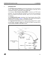
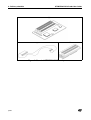
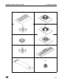
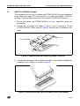
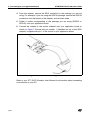
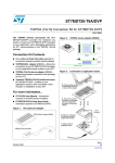
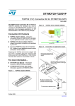
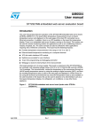
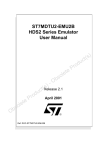
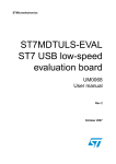
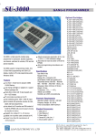
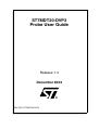
ST7MDT20-DVP3
Probe User Guide
Release 1.4
December 2004
Ref: DOC-ST7MDT20-DVP3
INSTRUCTIONS FOR USE—WARNING
This product is conform to the 89/336/EEC Directive. It complies with the ITE EN55022 (1998 edition)
standard for EMC emissions and the 55024 (1998 edition) immunity standards.
This product is an FCC Class-A apparatus. In a residential environment, it may cause
radioelectrical disturbances.
In addition, this development board is not contained in an outer casing; consequently, it cannot be
immune against electostatic discharges (ESD). Please refer to Appendix A EMC Conformity and Safety
Requirements on page 34 for relevant safety information.
USE IN LIFE SUPPORT DEVICES OR SYSTEMS MUST BE EXPRESSLY AUTHORIZED.
STMicroelectronics PRODUCTS ARE NOT AUTHORIZED FOR USE AS CRITICAL COMPONENTS IN
LIFE SUPPORT DEVICES OR SYSTEMS WITHOUT THE EXPRESS WRITTEN APPROVAL OF
STMicroelectronics. As used herein:
1. Life support devices or systems are those
which (a) are intended for surgical implant into
the body, or (b) support or sustain life, and whose
failure to perform, when properly used in
accordance with instructions for use provided
with the product, can be reasonably expected to
result in significant injury to the user.
2. A critical component is any component of a life
support device or system whose failure to
perform can reasonably be expected to cause the
failure of the life support device or system, or to
affect its safety or effectiveness.
Table of Contents
Chapter 1:
1.1
Introduction . . . . . . . . . . . . . . . . . . . . . . . . . . . . . . . . . . . . . . . . . . 5
About the user manuals... ............................................................................. 7
Chapter 2:
Delivery checklist . . . . . . . . . . . . . . . . . . . . . . . . . . . . . . . . . . . . . . 8
Chapter 3:
Connecting to your application board . . . . . . . . . . . . . . . . . . . . 12
3.1
3.2
3.3
3.4
3.5
3.6
3.7
Chapter 4:
4.1
4.2
Chapter 5:
SDIP42 and SDIP32 packages ................................................................... 13
TQFP80 (14 x 14) package ........................................................................ 15
TQFP64 (14 x 14) package ........................................................................ 16
TQFP64 (10 x 10) package ........................................................................ 17
TQFP44 (10 x 10) package ........................................................................ 18
TQFP32 (7 x 7) package ............................................................................ 19
Installing HE10 connectors on your application board ................................ 22
Emulation characteristics . . . . . . . . . . . . . . . . . . . . . . . . . . . . . . 29
On-chip peripherals configuration ............................................................... 29
Emulation functional limitations and discrepancies .................................... 31
Programming with your ST7MDT20-DVP3 . . . . . . . . . . . . . . . . . 33
Appendix A EMC Conformity and Safety Requirements . . . . . . . . . . . . . . . . 34
Product Support . . . . . . . . . . . . . . . . . . . . . . . . . . . . . . . . . . . . . . . . . . . . . . . . . 35
3/38
Table of Contents
4/38
ST7MDT20-DVP3 Probe User Guide
1
1 - Introduction
INTRODUCTION
The ST7-DVP3 series emulators are the latest generation of low cost emulators
for ST7. These emulators are based on a modular design so that they can be
configured to emulate a specific MCU and package type.
Your emulator’s Main Emulation Board (MEB) is common to all DVP3 series
emulators. This board provides the connection to your host PC. For information
about this connection and emulator features, refer to your ST7-DVP3 Emulator
User Manual.
The ST7MDT20-DVP3 probe, consisting of the Target Emulation Board (TEB),
Adapter Kit and flat cables (Figure 1), is what gives your emulator the versatility to
emulate MCUs from different families, with different packages.
The Target Emulation Board contains target-emulating hardware that is specific
to an ST7 MCU, or a family of MCUs. Your ST7MDT20-TEB/DVP emulates MCUs
in the ST72321, ST72324 and ST72521 families.
ST7MDT20-DVP3
Probe
Figure 1: ST7MDT25-DVP3 probe
5/38
1 - Introduction
ST7MDT20-DVP3 Probe User Guide
Flat cables connect your TEB to your application board. However, connecting to
your application board also requires the use of the appropriate adapters and
sockets provided in an Adapter Kit.
Adapter Kits provide all the components you will need to adapt the flat cables to
one of the supported MCU packages: TQFP80 (14 x 14), TQFP64 (14 x 14), TQFP64
(10 x 10), TQFP44 (10 x 10), TQFP32 (7 x 7), SDIP42, SDIP32. Table 2 provides a list of
components for each Adapter Kit. In general, Adapter Kits consist of (Figure 1):
•
An Adapter that receives the flat cables from the TEB and provides a
connection for the Device Adapter.
•
A Device Adapter that adapts the connection to a socket that is specific to
your MCU’s package.
•
A Socket that matches your MCUs package. It is soldered onto your
application board in place of your MCU.
•
It may also include one or more additional flat cables when necessary.
Thanks to the modularity of the ST7-DVP3 series emulators, the components of
the ST7MDT20-DVP3 probe allow you to adapt any DVP3 Main Emulation Board
to emulate MCUs in the ST72321, ST72324 and ST72521 families.
6/38
ST7MDT20-DVP3 Probe User Guide
1.1
1 - Introduction
About the user manuals...
This manual will help you connect your DVP3 emulator to your application board.
This document also contains information about the emulation characteristics of
your ST7MDT10-DVP3 probe and connection accessories.
For information about the software and additional hardware intended for use with
this TEB, refer to the following documents that are included with your emulator:
ST7 Visual Develop User Manual - build and debug your application software
ST7-DVP3 Emulator User Manual - set up instructions for your DVP3 emulator
ST7xxxx Datasheet - includes debugging and programming information that is
specific to your MCU
Because of the modularity of the DVP3 emulator, this guide is delivered with the
following kits:
1.1.1
•
ST7MDT20-TEB/DVP
•
ST7MDT20-DVP3 emulator
Revision history
Date
Revision
Description
Oct 2002
1.1
• Updated template and internal links
Apr 2003
1.2
• Updated supported devices
Apr 2004
1.3
• Updated Section 2– description of ordering codes
• Added Section 3.7– Pin descriptions for connecting flat
cables directly to the user’s application board
Dec 2004
1.4
• Added Table 1– Revision history table
• Replace “ST7 Visual Debug” with “ST7 Visual Develop”
• Replace “passive probe” terminology with adapter
• Updated Section 1– with improved description of product
structure
• Corrected Section 2– description of adapter kit ordering
codes
Table 1: ST7MDT20-DVP3 Probe User Guide revision history
7/38
2 - Delivery checklist
2
ST7MDT20-DVP3 Probe User Guide
DELIVERY CHECKLIST
The ST7MDT20-DVP3 TEB and connection accessories are typically delivered as
part of the ST7MDT20-DVP3 emulator. In addition to the items listed in this
section, the emulator contains the Main Emulation Board, power supply and the
connection cables needed to connect to your PC. For more information, refer to the
delivery check list in your ST7-DVP3 Emulator User Manual.
When ordering an ST7MDT20-DVP3 emulator, you will receive a complete
emulator (MEB, TEB and flat cables) along with adapters and sockets to emulate
microcontrollers in SDIP32 and SDIP42 packages. To received the connection
accessories to emulate microcontrollers in one of the other supported packages,
you must order the appropriate adapter kitadapter kit. Table 2 shows the
accessories delivered for each ordering code. They are illustrated in Figure 3.
If you already own an ST7-DVP3 emulator, your emulator’s MEB can be adapted
to emulate devices in the ST72321, ST72324 or ST72521 families with the
appropriate target emulation board (ordering code: ST7MDT20-TEB/DVP) and the
adapters and sockets that correspond to your microcontroller’s package.
Ordering code
ST7MDT20-DVP3
MCU
package
Contents
SDIP32
One ST7-DVP3 Main Emulation Board
(ref.: MB352) with the components listed in the
ST7-DVP3 Emulator User Manual.
SDIP42
(a) One ST7MDT20-DVP3 TEB (ref.: DB525)
(b) Two 50-pin flat cables.
(c) An SDIP/SDIP adapter (ref.: DB529)
(a) One ST7MDT20-DVP3 TEB (ref.: DB525)
ST7MDT20-TEB/
DVP
SDIP32
SDIP42
(b) Two 50-pin flat cables.
(c) An SDIP/SDIP adapter (ref.: DB529)
Does not include the ST7-DVP3 Main Emulation Board
(ref.: MB352) and associated components listed in the
ST7-DVP3 Emulator User Manual.
Table 2: Ordering codes and associated components
8/38
ST7MDT20-DVP3 Probe User Guide
Ordering code
2 - Delivery checklist
MCU
package
Contents
(b) 1 additional 50-pin flat cable1
ST7MDT20-T80/DVP
TQFP80
(14 x14)
(d) TQFP80/64/44 adapter (ref.: DB530)
(e) TQFP80 device adapter (ref.: DB531)
(f) YAMAICHI TQFP80 socket with cover
(ref.: IC149-080-051-S5)
(b) 1 additional 50-pin flat cable1
ST7MDT20-T64/DVP
TQFP64
(14 x 14)
(d) TQFP80/64/44 adapter (ref.: DB530)
(g) TQFP64 14x14 device adapter (ref.: DB543)
(h) TQFP64 socket and cover (not shown)
(refs. CAB 3303262 and CAB 3303307)
(b) 1 additional 50-pin flat cable1
MDT20-T6A/DVP
TQFP64
(10 x 10)
(d) TQFP80/64/44 adapter (ref.: DB530)
(e) TQFP64 10x10 device adapter (ref.: DB583)
(f) YAMAICHI TQFP64 10x10 socket with cover
(ref.: IC149-064-075-B5)
(b) 1 additional 50-pin flat cable1
ST7MDT20-T44/DVP
TQFP44
(10 x 10)
(d) TQFP80/64/44 adapter (ref.: DB530)
(i) TQFP44 device adapter (ref.: DB544)
(j) YAMAICHI TQFP44 socket with cover
(ref.: IC149-044-052-S5)
(k) TQFP32 adapter (ref.: DB545)
ST7MDT20-T32/DVP
TQFP32
(7x7)
2
(l) TQFP32 flex adapter (ref.: DB522)
(m) IRONWOOD TQFP32 connector
(ref.: SK-UGA06/32A-01)
Table 2: Ordering codes and associated components
1) Connecting the DB530 adapter to the emulator requires three 50-pin flat cables.
Two flat cables are already included in the ST7MDT20-DVP3.
2) You can replace the ST7MDT20-DVP3’s TQFP32 adapter with the actual ST7
by using an IRONWOOD clam shell socket (ref.: CA-QFE32SA-L-Z-T-02D1442). This socket is not provided with the adapter kitemulator.
9/38
2 - Delivery checklist
ST7MDT20-DVP3 Probe User Guide
(a)
(b)
(c)
Figure 2: Standard ST7MDT20-DVP3 components
10/38
ST7MDT20-DVP3 Probe User Guide
2 - Delivery checklist
(d)
(e)
(f)
(g)
(h)
(i)
(j)
(k)
(l)
(m)
Figure 3: Adapter kit components
11/38
3 - Connecting to your application board
3
ST7MDT20-DVP3 Probe User Guide
CONNECTING TO YOUR APPLICATION BOARD
In addition to providing the firmware to emulate your MCU, the ST7MDT20-DVP3
emulator serves as the hardware interface between your host PC and your
application. Your DVP3 emulator comes with the connectors and adapters for a
specific package type. These accessories allow you to connect your emulator to
your application board in place of your ST7 microcontroller.
ST7MDT20-DVP3 emulator with
SDIP42 adapter
DVP3 Main
Emulation Board
ST7MDT20-DVP3
Target Emulation Board
50-pin flat cables
Adapter connected
to MCU socket on
the application board
Figure 4: DVP3 to application board connection
You can also install two or three HE10 type connectors (depending on the MCU
you wish to emulate) directly on your application board. Doing so will allow you to
connect the emulator to your application board without using a device adapter or
socket.
This chapter provides information about connecting to your application board:
12/38
•
Section 3.1 — for microcontrollers in a SDIP32 and SDIP42 packages
•
Section 3.2 — for microcontrollers in a TQFP80 (14 x 14) package
•
Section 3.3 — for microcontrollers in a TQFP64 (14 x 14) package
•
Section 3.4 — for microcontrollers in a TQFP64 (10 x 10) package
•
Section 3.5 — for microcontrollers in a TQFP44 (10 x 10) package
•
Section 3.6 — for microcontrollers in a TQFP32 (7 x 7) package
•
Section 3.7 — with HE10 connectors installed on the application board
ST7MDT20-DVP3 Probe User Guide
3.1
3 - Connecting to your application board
SDIP42 and SDIP32 packages
This procedure tells you how to connect the ST7MDT20-DVP3 to your application
board when your target ST7 microcontroller is in either the SDIP42 or SDIP32
package. These packages require only the standard ST7MDT20-DVP3 parts.
1
Ensure that neither the ST7MDT20-DVP3 nor your application board are
powered up.
2
Connect the two 50-pin flat cables to the J1 and J2 connectors on the
ST7MDT20-DVP3 TEB as shown in Figure 5. Note that the J3 connector is not
used.
J3 is not used
Figure 5: Connecting the two 50-pin flat cables to the TEB
3
Connect the other end of the two 50-pin flat cables to the adapter provided with
standard kit (ref.: DB529), as shown in Figure 6.
Figure 6: Connecting the two 50-pin flat cables to the SDIP adapter
13/38
3 - Connecting to your application board
ST7MDT20-DVP3 Probe User Guide
4
From the adapter, remove the SDIP connector for the package you are not
using. For example, if you are using the SDIP42 package, remove the SDIP32
connectors from the bottom of the adapter, and set them aside.
5
Solder a socket corresponding to the package you are using (SDIP32 or
SDIP42) onto your application board.
6
Connect the adapter to the socket soldered onto your application board as
shown in Figure 7. Ensure that pin number 1 (identified on top of the SDIP
adapter) is aligned with pin 1 of the socket on your application board.
Figure 7: SDIP connection to application board
Refer to your ST7-DVP3 Emulator User Manual for information about connecting
your emulator to your PC.
14/38
ST7MDT20-DVP3 Probe User Guide
3.2
3 - Connecting to your application board
TQFP80 (14 x 14) package
To connect the ST7MDT20-DVP3 to your application board when your target ST7
microcontroller is in the TQFP80 package, you will need the ST7MDT20-DVP3
with the ST7MDT20-T80/DVP adapter kit.
1
Ensure that the emulator and application board are powered off.
2
Connect one end of each of the three 50-pin flat cables to connectors J1, J2 and
J3 on the ST7MDT20-DVP3 TEB.
3
Connect the other end of each of the three 50-pin flat cables to the TQFP80/64/
44 adapter (ref.: DB530), as shown in Figure 8.
4
Solder the TQFP80 (14 x 14) Yamaichi socket onto your application board.
5
Fix the device adapter (ref.: DB531) to the Yamaichi socket that is soldered on
your application board, using the provided screws (see Figure 8). Ensure that
the device adapter’s pin 1 indicator is aligned with the socket’s pin 1 indicator.
Flat cables
Adapter
Device adapter
Pin 1 indicators
Socket
Figure 8: Connection for TQFP80
6
Connect the adapter to the device adapter as shown in Figure 8.
Refer to your ST7-DVP3 Emulator User Manual for information about connecting
your emulator to your PC.
15/38
3 - Connecting to your application board
3.3
ST7MDT20-DVP3 Probe User Guide
TQFP64 (14 x 14) package
To connect the ST7MDT20-DVP3 to your application board when your target ST7
microcontroller is in the TQFP64 package, you will need the ST7MDT20-DVP3
with the ST7MDT20-T64/DVP adapter kit.
1
Ensure that the emulator and application board are powered off.
2
Connect one end of each of the three 50-pin flat cables to connectors J1, J2 and
J3 on the ST7MDT20-DVP3 TEB.
3
Connect the other end of each of the three 50-pin flat cables to the TQFP80/64/
44 adapter (ref.: DB543), as shown in Figure 9.
4
Solder the TQFP64 (14 x 14) socket onto your application board.
5
Fix the device adapter (ref.: DB531) to the socket soldered on your application
board using the provided screws (see Figure 9). Ensure that the device
adapter’s pin 1 indicator is aligned with the socket’s pin 1 indicator.
Flat cables
Adapter
Device adapter
Pin 1 indicators
(flat corner on the socket)
Socket
Figure 9: Connection for TQFP64
6
Connect the adapter to the device adapter as shown in Figure 9.
Refer to your ST7-DVP3 Emulator User Manual for information about connecting
your emulator to your PC.
16/38
ST7MDT20-DVP3 Probe User Guide
3.4
3 - Connecting to your application board
TQFP64 (10 x 10) package
To connect the ST7MDT20-DVP3 to your application board when your target ST7
microcontroller is in the TQFP64 10x10 package, you will need the ST7MDT20DVP3 with the ST7MDT20-T6A/DVP adapter kit.
1
Ensure that the emulator and application board are powered off.
2
Connect the one end of each of the three 50-pin flat cables to connectors J1, J2
and J3 on the ST7MDT20-DVP3 TEB.
3
Connect the other end of each of the three 50-pin flat cables to the TQFP80/64/
44 adapter (ref.: DB530), as shown in Figure 10.
4
Solder the TQFP64 (10 x 10) Yamaichi socket onto your application board.
5
Fix the device adapter (ref.: DB583) to the Yamaichi socket soldered on your
application board using the provided screws (see Figure 10). Ensure that the
device adapter’s pin 1 indicator is aligned with the socket’s pin 1 indicator.
Flat cables
Adapter
Device adapter
Pin 1 indicators
Socket
Figure 10: Connection for TQFP64 10x10
6
Connect the adapter to the device adapter as shown in Figure 10.
Refer to your ST7-DVP3 Emulator User Manual for information about connecting
your emulator to your PC.
17/38
3 - Connecting to your application board
3.5
ST7MDT20-DVP3 Probe User Guide
TQFP44 (10 x 10) package
To connect the ST7MDT20-DVP3 to your application board when your target ST7
microcontroller is in the TQFP44 package, you will need the ST7MDT20-DVP3
with the ST7MDT20-T44/DVP adapter kit.
1
Ensure that the emulator and application board are powered off.
2
Connect the one end of each of the three 50-pin flat cables to connectors J1, J2
and J3 on the ST7MDT20-DVP3 TEB.
3
Connect the other end of each of the three 50-pin flat cables to the TQFP80/64/
44 adapter (ref.: DB530), as shown in Figure 11.
4
Solder the TQFP44 (10 x 10) Yamaichi socket onto your application board.
5
Fix the device adapter (ref.: DB544) to the Yamaichi socket soldered on your
application board using the provided screws (see Figure 11). Ensure that the
device adapter’s pin 1 indicator is aligned with the socket’s pin 1 indicator.
Flat cables
Adapter
Device adapter
Pin 1 indicators
Socket
Figure 11: Connection for TQFP44
6
Connect the adapter to the device adapter as shown in Figure 11.
Refer to your ST7-DVP3 Emulator User Manual for information about connecting
your emulator to your PC.
18/38
ST7MDT20-DVP3 Probe User Guide
3.6
3 - Connecting to your application board
TQFP32 (7 x 7) package
To connect the ST7MDT20-DVP3 to your application board when your target ST7
microcontroller is in the TQFP32 package, you will need the ST7MDT20-DVP3
with the ST7MDT20-T32/DVP adapter kit.
Because of the small size of the TQFP32 connector, a specific flex adapter has
been designed in order to minimize the mechanical stress applied to this
connector.
1
Ensure that the emulator and application board are powered off.
2
Connect the DB522 flex adapter to the TEB adapter (ref.: DB545) as shown in
Figure 12
Figure 12: Flex PCB mounted on TEB adapter
19/38
3 - Connecting to your application board
3
ST7MDT20-DVP3 Probe User Guide
Connect the TEB adapter to connectors J1 and J2 of the ST7MDT20-DVP3
TEB as shown in Figure 13.
Figure 13: DVP3 configuration for TQFP32 emulation
4
Solder the TQFP32 connector (Ironwood SK-UGA06/32A-01) onto your
application board as shown in Figure 14
Pin 1 indicators
Figure 14: TQFP32 connector
5
20/38
Connect the flex adapter to the TQFP32 connector, ensuring that pin 1 of the
flex cable adapter is aligned with pin 1 of the socket. Pin 1 is identified by a
white triangle.
ST7MDT20-DVP3 Probe User Guide
Note:
3 - Connecting to your application board
The TQFP32 connector provided in the adapter kit does not support the replacement of the
flex cable by an actual ST7 TQFP32 device. This can be done if you use an IRONWOOD
clam shell socket (ref.: CA-QFE32SA-L-Z-T-02-D1442), which is not provided with the kit.
Refer to your ST7-DVP3 Emulator User Manual for information about connecting
your emulator to your PC.
21/38
3 - Connecting to your application board
3.7
ST7MDT20-DVP3 Probe User Guide
Installing HE10 connectors on your application board
This section provides information about installing connectors on your application
board for the connection with your emulator. Doing this will allow you to connect
your emulator to the application board without using the device adapters and/or
sockets described in the preceding sections. To do this you can install connectors
on your application board that correspond to W1 and W2 connectors of the DB530
adapter, or to the 50-pin flat cable connectors.
Whichever option you choose, you will have to orient all connectors correctly and
ensure the necessary pin connections according to the specifications provided in
this section.
3.7.1
Orientation of the connectors
To receive the DB530 flat cable adapter
When designing your application board with the 40-pin, SAMTEC connectors
corresponding to W1 and W2 on the flat cable adapter, be sure to orient them
correctly. The schematic in Figure 15 shows the orientation of the W1 and W2
connectors in relation to the adapter’s J1, J2 and J3 connectors.
1400 mils
(35.65 mm)
DB530 Adapter
(top view)
Figure 15: Orientation of J1 and J2 connectors
W1 and W2 on this adapter are SAMTEC connectors (REF.: TFM 120-22-S-D-A).
When installing the corresponding connectors to receive the W1 and W2
connectors, you must ensure a distance of 1400 mills between the connectors,
measured as shown in Figure 15.
22/38
ST7MDT20-DVP3 Probe User Guide
3 - Connecting to your application board
To receive emulator flex cables
You can also choose to install 50-pin HE10 connectors on your application board
to receive the emulator’s flex cables. In this case ensure that the orientation
corresponds to that used for the adapter DB530 (see Figure 15).
3.7.2
Relaying the connectors to your application
The following sections provide the pin specifications required for connecting your
emulator to your application board.
When installing the 40-pin connectors corresponding to W1 and W2 on your
application board, follow the pin correspondence provided for:
•
W1 (40-pin HE10 type connector) in Table 3
•
W2 (40-pin HE10 type connector) in Table 4
When installing the 50-pin HE10 connectors corresponding to J1, J2 and J3 on
your application board, follow the pin correspondence provided for:
•
J1 (50-pin HE10 type connector) in Table 5
•
J2 (50-pin HE10 type connector) in Table 6
•
J3 (50-pin HE10 type connector) in Table 7
23/38
3 - Connecting to your application board
ST7MDT20-DVP3 Probe User Guide
Pin specification for W1 connector:
Pin N°
Name
Description/
Comments
Pin N°
Name
Description/
Comments
1
PH6
I/O port H bit 6
2
PH7
I/O port H bit 7
3
GND
to connect to GND
4
OSC2
also called OSCOUT
5
OSC1
also called “OSCIN”
6
VCC
Main Supply Voltage
7
PE0
I/O port E bit 0
8
PE1
I/O port E bit 1
9
PE2
I/O port E bit 2
10
PE3
I/O port E bit 3
11
PE4
I/O port E bit 4
12
PE5
I/O port E bit 5
13
PE6
I/O port E bit 6
14
PE7
I/O port E bit 7
15
PB0
I/O port B bit 0
16
PB1
I/O port B bit 1
17
PB2
I/O port B bit 2
18
PB3
I/O port B bit 3
19
PG0
I/O port G bit 0
20
PG1
I/O port G bit 1
21
PG2
I/O port G bit 2
22
PG3
I/O port G bit 3
23
PB4
I/O port B bit 4
24
PB5
I/O port B bit 5
25
PB6
I/O port B bit 6
26
PB7
I/O port B bit 7
27
PD0
I/O port D bit 0
28
PD1
I/O port D bit 1
29
PD2
I/O port D bit 2
30
PD3
I/O port D bit 3
31
PG6
I/O port G bit 6
32
PG7
I/O port G bit 7
33
PD4
I/O port D bit 4
34
PD5
I/O port D bit 5
35
PD6
I/O port D bit 6
36
PD7
I/O port D bit 7
37
VAREF
ADC analog reference
38
39
VCC
Main Supply Voltage
40
GND
to connect to GND
Table 3: Pin correspondence for W1 connector
24/38
ST7MDT20-DVP3 Probe User Guide
3 - Connecting to your application board
Pin specification for W2 connector:
Pin N°
Description/
Comments
Name
Pin N°
Name
Description/
Comments
1
PH4
I/O port H bit 4
2
PH5
I/O port H bit 5
3
EVD
External Voltage
Detector
4
TLI
Top Level Interrupt
5
reserved
6
/RESET MCU reset
7
PA6
I/O port A bit 6
8
PA7
I/O port A bit 7
9
PA4
I/O port A bit 4
10
PA5
I/O port A bit 5
11
VCC
Main Supply Voltage
12
GND
to connect to GND
13
PA2
I/O port A bit 2
14
PA3
I/O port A bit 3
15
PA0
I/O port A bit 0
16
PA1
I/O port A bit 1
17
PC6
I/O port C bit 6
18
PC7
I/O port C bit 7
19
PH2
I/O port H bit 2
20
PH3
I/O port H bit 3
21
PH0
I/O port H bit 0
22
PH1
I/O port H bit 1
23
PC4
I/O port C bit 4
24
PC5
I/O port C bit 5
25
PC2
I/O port C bit 2
26
PC3
I/O port C bit 3
27
PC0
I/O port C bit 0
28
PC1
I/O port C bit 1
29
VCC
Main Supply Voltage
30
GND
to connect to GND
31
PF6
I/O port F bit 6
32
PF7
I/O port F bit 7
33
PF4
I/O port F bit 4
34
PF5
I/O port F bit 5
35
PF2
I/O port F bit 2
36
PF3
I/O port F bit 3
37
PF0
I/O port F bit 0
38
PF1
I/O port F bit 1
39
PG4
I/O port G bit 4
40
PG5
I/O port G bit 5
Table 4: Pin correspondence for W1 connector
Caution:
Pin #5 is reserved and must not be connected.
25/38
3 - Connecting to your application board
ST7MDT20-DVP3 Probe User Guide
Pin specification for J1 connector:
Pin N°
Description/
Comments
Name
Pin N°
Description/
Comments
Name
1
GND
to connect to GND
2
GND
3
PC7
I/O Port C bit 7
4
reserved
5
EVD
External Voltage
Detector
6
7
PD0
I/O port D bit 0
8
9
PD1
I/O port D bit 1
10
11
PD2
I/O port D bit 2
12
13
PD3
I/O port D bit 3
14
15
PD4
I/O port D bit 4
16
17
PD5
I/O port D bit 5
18
19
reserved
21
VAREF
ADC analog reference
22
23
VCC
Main Supply Voltage
24
25
PE0
I/O port E bit 0
26
27
PE1
I/O port E bit 1
28
29
PC6
I/O port C bit 6
30
31
TLI
Top Level Interrupt
32
33
OSC2
also called
“OSCOUT”
34
35
PF0
I/O port F bit 0
36
37
PF1
I/O port F bit 1
38
39
PF2
I/O port F bit 2
40
41
PF3
I/O port F bit 3
42
43
PF4
I/O port F bit 4
44
45
PF5
I/O port F bit 5
46
47
PF6
I/O port F bit 6
48
reserved
49
PF7
I/O port F bit 7
50
GND
GND
to connect to GND
to connect to GND
reserved
20
GND
to connect to GND
reserved
GND
to connect to GND
to connect to GND
Table 5: Pin correspondence for J1 connector
Caution:
26/38
Pins #4, 18, 19, 34 and 48 are reserved. They must not be connected.
ST7MDT20-DVP3 Probe User Guide
3 - Connecting to your application board
Pin specification for J2 connector:
Pin N°
Name
Description/
Comments
Pin N°
Name
1
GND
to connect to GND
2
GND
3
PA0
I/O port A bit 0
4
reserved
5
PA1
I/O port A bit 1
6
7
PA2
I/O port A bit 2
8
9
PA3
I/O port A bit 3
10
11
PA4
I/O port A bit 4
12
13
PA5
I/O port A bit 5
14
15
PA6
I/O port A bit 6
16
17
PA7
I/O port A bit 7
18
19
/RESET MCU reset
20
21
PB0
I/O port B bit 0
22
23
PB1
I/O port B bit 1
24
25
PB2
I/O port B bit 2
26
27
PB3
I/O port B bit 3
28
29
PB4
I/O port B bit 4
30
31
PB5
I/O port B bit 5
32
33
PB6
I/O port B bit 6
34
35
PB7
I/O port B bit 7
36
37
OSC1
also called “OSCIN”
38
39
PC0
I/O port C bit 0
40
41
PC1
I/O port C bit 1
42
43
PC2
I/O port C bit 2
44
45
PC3
I/O port C bit 3
46
47
PC4
I/O port C bit 4
48
reserved
49
PC5
I/O port C bit 5
50
GND
GND
Description/
Comments
to connect to GND
to connect to GND
reserved
GND
to connect to GND
reserved
GND
to connect to GND
to connect to GND
Table 6: Pin correspondence for W1 connector
Caution:
Pins #4, 18, 34 and 48 are reserved. They must not be connected.
27/38
3 - Connecting to your application board
ST7MDT20-DVP3 Probe User Guide
Pin specification for J3 connector:
Pin N°
Description/
Comments
Name
1
reserved
3
PD6
5
Pin N°
Name
2
GND
I/O port D bit 6
4
reserved
PD7
I/O port D bit 7
6
7
PE2
I/O port E bit 2
8
9
PE3
I/O port E bit 3
10
11
PE4
I/O port E bit 4
12
13
PE5
I/O port E bit 5
14
15
PE6
I/O port E bit 6
16
17
PE7
I/O port E bit 7
18
19
PG0
I/O port G bit 0
20
21
PG1
I/O port G bit 1
22
23
PG2
I/O port G bit 2
24
25
PG3
I/O port G bit 3
26
27
PG4
I/O port G bit 4
28
29
PG5
I/O port G bit 5
30
31
PG6
I/O port G bit 6
32
33
PG7
I/O port G bit 7
34
35
PH0
I/O port H bit 0
36
37
PH1
I/O port H bit 1
38
39
PH2
I/O port H bit 2
40
41
PH3
I/O port H bit 3
42
43
PH4
I/O port H bit 4
44
45
PH5
I/O port H bit 5
46
47
PH6
I/O port H bit 6
48
reserved
49
PH7
I/O port H bit 7
50
GND
GND
Description/
Comments
to connect to GND
to connect to GND
reserved
GND
to connect to GND
reserved
GND
to connect to GND
to connect to GND
Table 7: Pin correspondence for W1 connector
Caution:
28/38
Pins #1, 4, 18, 34 and 48 are reserved. They must not be connected.
ST7MDT20-DVP3 Probe User Guide
4 - Emulation characteristics
4
EMULATION CHARACTERISTICS
4.1
On-chip peripherals configuration
You can configure certain on-chip peripherals in ST7 Visual Develop’s MCU
Configuration dialog box so that the ST7-DVP3 accurately emulates your target
device.
The on-chip peripheral options available for configuration for the ST7MDT20-DVP3
are described in this section.
MCU
The MCU Selection tab in STVD7’s Project Settings window allows you to select
from a list of MCUs that are supported by the software. The STVD7 release notes
provide the most up to date list of supported microcontrollers for your emulator.
FOSC
The clock frequency (FOSC) options are summarized in Table 8 below.
Clock options
Clock Source Location
16 MHz
8 MHz
4 MHz
2 MHz
On probe
External
Provided by user via the EXTCLK pin on connector
W3 of the ST7 DVP3 MEB (MB352)
Table 8: Clock frequency options
FCPU
The CPU frequency (FCPU) is always in the range from 250 KHz to 8 MHz even if
slow mode or PLL are selected.
The link between FCPU and FOSC is the following:
-
if PLL is OFF:
FCPU = (FOSC / 2) / Slow mode
-
if PLL is ON:
FCPU = (FOSC * 2) / Slow mode
29/38
4 - Emulation characteristics
ST7MDT20-DVP3 Probe User Guide
Timer_A and Timer_B
Two 16-bit timers, Timer A and Timer B, are available. They consist of a 16-bit
free-running counter driven by a programmable prescaler. Both timers feature
output compare, pulse width modulation (PWM) and input capture functions with
associated registers.
You can choose between two options: Frozen_when_not_run and
Free_when_not_run. If you choose the Frozen_when_not_run option, the
counter will run while the application runs, but when a breakpoint is encountered,
the counter will stop. If you choose the Free_when_not_run option, the counter
will continue to run even if a breakpoint is encountered.
Note:
The EXTCLK_A pin of the timer is not frozen when the program is stopped.
CSS (Clock Security System)
This option allows you to Enable or Disable the clock security system function
(CSS) which includes the clock filter and the backup safe oscillator. When enabled,
the selected OSCRANGE is used to determine the operating frequency range, and
when the frequency is out of range, the clock source will be switched to the backup
oscillator.
OSCRANGE
This option allows you to select the normal operating frequency range for the Clock
Security System (CSS). The following operating frequency range options are
available:
•
HS: 16..8 MHz
•
MS: 8..4 MHz
•
MP: 4..2 MHz
•
LP: 2..1 MHz
PLL
This option allows you to Enable or Disable the PLL which allows the multiplication
by two of the main input clock frequency. The PLL is guaranteed only when the
input frequency is between 2 and 4 MHz.
Refer to the datasheet of your target ST7 MCU for more information on the PLL.
30/38
ST7MDT20-DVP3 Probe User Guide
4 - Emulation characteristics
RSTC (Reset clock cycle selection)
This option allows you to select the number of CPU cycles applied during the
RESET phase and when exiting HALT mode. You can choose between 4096 CPU
cycles and 256 CPU cycles.
VD (Voltage detection)
This option allows you to enable the voltage detection block (EVD only) with a
selected lowest threshold for the LVD and AVD (VDD ~3v). This option is available
only for packages having EVD pin (80 & 64 pins).The options available are:
•
EVD_off — EVD is disabled.
•
EVD_on — EVD is enabled
Refer to Emulation functional limitations and discrepancies on page 31 for more
information.
WDG.HALT (Watchdog halt)
There are two options: Reset or No Reset. If this option is set to Reset, when the
Watchdog is enabled and a Halt instruction is encountered in the executable code,
a chip reset will be performed. If this option is set to No Reset, no chip reset will be
performed.
WDG.SW (Watchdog)
This option allows you to choose whether the watchdog timer is enabled by
software or by hardware.
Refer to the datasheet of your target ST7 MCU for more information on the
watchdog timer.
4.2
Emulation functional limitations and discrepancies
•
All evolutions of discrepancies according to the hardware used are available in
a specific window of the debugger. You can access to this information in ST7
Visual Develop’s Emulator discrepancies dialog box under Emulator menu.
•
In reference to the option VD (Voltage detection) on page 31:
•
The LVD option is always turned off in HALT/Active HALT mode, no matter
what the selected VD option is.
Power supply configuration of the ST7 DVP3 can be either 3.3 V or 5 V through
the SW1 switch located on the ST7-DVP3 MEB (DB352). Consequences on
Port I/Os are the following:
31/38
4 - Emulation characteristics
32/38
ST7MDT20-DVP3 Probe User Guide
-
Port G and H I/Os are always TTL 3.3 V compatible whatever the SW1
position chosen.
-
Other than Port G and H I/Os are 3.3 V or 5 V CMOS compatible
depending of the SW1 position chosen.
ST7MDT20-DVP3 Probe User Guide
5
5 - Programming with your ST7MDT20-DVP3
PROGRAMMING WITH YOUR ST7MDT20-DVP3
Once bug-free and ready for operation, your application program needs to be
transferred into an ST7 MCU program space.
Refer to the ST7-DVP3 Emulator User Manual for instructions on how to program
using STVP7.
33/38
Appendix A EMC Conformity and Safety Requirements
ST7MDT20-DVP3 Probe User Guide
APPENDIX A EMC CONFORMITY AND SAFETY REQUIREMENTS
This product respects the EMC requirements of the European guideline 89/336/
EEC under the following conditions:
•
Any tester, equipment, or tool used at any production step, or for any
manipulation of semiconductor devices, must have its shield connected to
ground.
•
All provided ferrites must be attached as described in the hardware installation
instructions of the relevant user manual(s).
•
The product must be placed on a conductive table top, made of steel or clean
aluminum, or covered by an antistatic surface (superficial resistivity equal to or
higher than 0.5 MΩ/cm2), grounded through a ground cable (conductive cable
from protected equipment to ground isolated with a 1 MΩ resistor placed in
series). All manipulation of finished must be done at such a grounded
worktable.
34/38
•
The worktable must be free of all non-antistatic plastic objects.
•
An antistatic floor covering grounded through a conductive ground cable (with
serial resistor between 0.9 and 1.5 MΩ) should be used.
•
It is recommended that you wear an antistatic wrist or ankle strap, connected to
the antistatic floor covering or to the grounded equipment.
•
If no antistatic wrist or ankle strap is worn, before each manipulation of the
powered-on tool, you must touch the surface of the grounded worktable.
•
It is recommended that antistatic gloves or finger coats be worn.
•
It is recommended that nylon clothing be avoided while performing any
manipulation of parts.
•
If you are using this product under conditions where there may be blackouts or
power surges (such as during an electrical storm), it is recommended that you
isolate it by elevating it at least 10 cm above the grounded work surface using
blocks of insulating material.
ST7MDT20-DVP3 Probe User Guide
Product Support
PRODUCT SUPPORT
If you experience any problems with this product, or if you need spare parts or
repairs, contact the distributor or the STMicroelectronics sales office where you
purchased the product. Phone numbers for major sales regions are provided in the
Contact List, below.
In addition, at our Internet site mcu.st.com, you will find a complete listing of ST
sales offices and distributors, as well as documentation, software downloads and
user discussion groups to help you answer questions and stay up to date with our
latest product developments.
Software updates
All our latest software and related documentation are available for download from
the ST Internet site, mcu.st.com. For information about firmware and hardware
revisions, call your distributor or ST using the Contact List provided below.
Hardware spare parts
Your development tool comes with the hardware you need to set it up, connect it to
your PC and connect to your application. However, some components can be
bought separately if you need additional ones. You can order extra components,
such as sockets and adapters, from STMicroelectronics, from the component
manufacturer or from a distributor.
Sockets
Complete documentation and ordering information for P/TQFP sockets from
Yamaichi, Ironwood, CAB and Enplas are provided at the following Internet sites:
www.yamaichi.de
www.ironwoodelectronics.com
www.cabgmbh.com
www.enplas.com
Connectors
Complete documentation and ordering information for SAMTEC connectors is
provided at www.samtec.com.
35/38
Product Support
ST7MDT20-DVP3 Probe User Guide
Getting prepared before you call
Collect the following information about the product before contacting ST or your
distributor:
36/38
1
Name of the company where you purchased the product.
2
Date of purchase.
3
Order Code: Refer to the side your emulators box. The order code will depend
on the region in which is was ordered (i.e. the UK, Continental Europe or the
USA).
4
Serial Number: The serial number is found on the Global Reference card
provided with the emulator.
5
TEB (Target Emulation Board) hardware and firmware versions: The hardware
and firmware versions can be found by opening an STVD7 session, entering
the debug context and selecting Help>About from the main menu. The TEB
version numbers are given in the Target box – scroll downwards until you find
the TEB version (hardware) and TEB PLD version (firmware).
6
Target Device: The sales type of the ST microcontroller you are using in your
application.
ST7MDT20-DVP3 Probe User Guide
Product Support
Contact List
North America
Canada and East Coast
Mid West
STMicroelectronics
Lexington Corporate Center
10 Maguire Road, Building 1, 3rd floor
Lexington, MA 02421
Phone: (781) 402-2650
STMicroelectronics
1300 East Woodfield Road, Suite 410
Schaumburg, IL 60173
Phone: (847) 585-3000
West coast
STMicroelectronics, Inc.
1060 E. Brokaw Road
San Jose, CA 95131
Phone: (408) 452-8585
Note:
For American and Canadian customers seeking technical support the US/
Canada is split in 3 territories. According to your area, contact the appropriate
sales office from the list above and ask to be transferred to an 8-bit
microcontroller Field Applications Engineer.
Europe
France +33 (0)1 47 40 75 75
Germany +49 89 46 00 60
U.K. +44 162 889 0800
Asia/Pacific Region
Japan +81 3 3280 4120
Hong-Kong +85 2 2861 5700
Sydney +61 2 9580 3811
Taipei +88 6 2 2378 8088
37/38
3
8
Information furnished is believed to be accurate and reliable. However, STMicroelectronics assumes no responsibility for the
consequences of use of such information nor for any infringement of patents or other rights of third parties which may result from its use.
No license is granted by implication or otherwise under any patent or patent rights of STMicroelectronics. Specifications mentioned in this
publication are subject to change without notice. This publication supersedes and replaces all information previously supplied.
STMicroelectronics products are not authorized for use as critical components in life support devices or systems without express written
approval of STMicroelectronics.
The ST logo is a registered trademark of STMicroelectronics.
All other names are the property of their respective owners
© 2004 STMicroelectronics - All rights reserved
STMicroelectronics group of companies
Australia – Belgium - Brazil - Canada - China – Czech Republic - Finland - France - Germany - Hong Kong - India - Israel - Italy - Japan Malaysia - Malta - Morocco - Singapore - Spain - Sweden - Switzerland - United Kingdom - United States of America
www.st.com