1
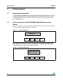
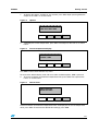
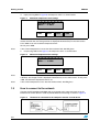
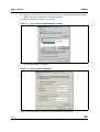
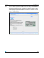
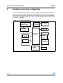
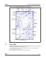
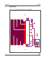
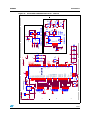
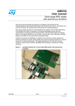
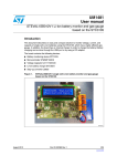
UM0504
User manual
ST72321M9 embedded web server evaluation board
Introduction
This user manual describes the operation of the ST72321M9 embedded web server board.
(STEVAL-CDE001V1). The board offers temperature measurement via an on-board
temperature sensor and displays it on the web page of the client PC connected via an
Ethernet connection. In addition, there is an LCD available on the board for temperature
display. There is an embedded web server firmware running on the board. This system can
be used for remote monitoring solution for applications such as air conditioning control in
industry, hospitals, etc. The same concept can also be utilized for other applications
requiring web or Ethernet connectivity. The board has the following features:
■
Provides temperature measurements in the range of -55 °C to 150 °C
■
Ethernet-based temperature monitoring on a computer terminal
■
16*2 dot matrix interface LCD module
■
Switches are provided for user interface
■
10-pin ICC programming and debugging connector
■
Webpage is stored in internal flash of the microcontroller
The board operates on 5 V power supply. The board is comprised of the ST72F321M9 as
the controller, with operating voltage range of 3.8 V to 5.5 V, Flash 60 KB, and the LQFP80
14x14 package. The microcontroller senses the temperature of the environment through an
LM135 analog temperature sensor by using the analog-to-digital converter (ADC), and then
the resulting temperature value is sent to the web page and displayed in HTML format on
the computer terminal via the Ethernet hub. Since the temperature value is also available on
the LCD mounted on the board, this can be used in absence of a web interface such as a
front panel temperature display of a refrigerator, air conditioner, or any other home
appliance.
Figure 1.
April 2008
ST72321M9 embedded web server board (order code: STEVALCDE001V1)
Rev 1
1/37
www.st.com
Contents
UM0504
Contents
1
2
3
2/37
Getting started . . . . . . . . . . . . . . . . . . . . . . . . . . . . . . . . . . . . . . . . . . . . . . 6
1.1
Powering on the board . . . . . . . . . . . . . . . . . . . . . . . . . . . . . . . . . . . . . . . . 6
1.2
User interface to the ST72321M9 embedded web server board . . . . . . . . 6
1.3
How to connect to the network . . . . . . . . . . . . . . . . . . . . . . . . . . . . . . . . . . 8
Hardware layout and configuration . . . . . . . . . . . . . . . . . . . . . . . . . . . . 12
2.1
Power supply . . . . . . . . . . . . . . . . . . . . . . . . . . . . . . . . . . . . . . . . . . . . . . 13
2.2
Clock source . . . . . . . . . . . . . . . . . . . . . . . . . . . . . . . . . . . . . . . . . . . . . . . 14
2.3
Reset source . . . . . . . . . . . . . . . . . . . . . . . . . . . . . . . . . . . . . . . . . . . . . . 14
2.4
Temperature sensor . . . . . . . . . . . . . . . . . . . . . . . . . . . . . . . . . . . . . . . . . 15
2.5
Potentiometer R23 . . . . . . . . . . . . . . . . . . . . . . . . . . . . . . . . . . . . . . . . . . 15
2.6
Serial Flash . . . . . . . . . . . . . . . . . . . . . . . . . . . . . . . . . . . . . . . . . . . . . . . 15
2.7
SPI serial bus EEPROM . . . . . . . . . . . . . . . . . . . . . . . . . . . . . . . . . . . . . . 16
2.8
Potentiometer R43 . . . . . . . . . . . . . . . . . . . . . . . . . . . . . . . . . . . . . . . . . . 16
2.9
Potentiometer R47 . . . . . . . . . . . . . . . . . . . . . . . . . . . . . . . . . . . . . . . . . . 16
2.10
Potentiometer R14 . . . . . . . . . . . . . . . . . . . . . . . . . . . . . . . . . . . . . . . . . . 17
2.11
Display devices . . . . . . . . . . . . . . . . . . . . . . . . . . . . . . . . . . . . . . . . . . . . . 17
2.12
Switches . . . . . . . . . . . . . . . . . . . . . . . . . . . . . . . . . . . . . . . . . . . . . . . . . . 18
2.13
Ethernet driver RTL8019AS . . . . . . . . . . . . . . . . . . . . . . . . . . . . . . . . . . . 18
2.14
RS232 level converter U6 . . . . . . . . . . . . . . . . . . . . . . . . . . . . . . . . . . . . . 18
2.15
Level shifter U10 . . . . . . . . . . . . . . . . . . . . . . . . . . . . . . . . . . . . . . . . . . . . 18
2.16
Charge pump . . . . . . . . . . . . . . . . . . . . . . . . . . . . . . . . . . . . . . . . . . . . . . 19
2.17
LEDs . . . . . . . . . . . . . . . . . . . . . . . . . . . . . . . . . . . . . . . . . . . . . . . . . . . . 19
2.18
Development and debug support . . . . . . . . . . . . . . . . . . . . . . . . . . . . . . . 19
Connector details . . . . . . . . . . . . . . . . . . . . . . . . . . . . . . . . . . . . . . . . . . 20
3.1
Power supply connector . . . . . . . . . . . . . . . . . . . . . . . . . . . . . . . . . . . . . . 20
3.2
RS232 connector VB1 . . . . . . . . . . . . . . . . . . . . . . . . . . . . . . . . . . . . . . . 20
3.3
ICC connector J29 . . . . . . . . . . . . . . . . . . . . . . . . . . . . . . . . . . . . . . . . . . 21
3.4
Serial Flash connector J16 . . . . . . . . . . . . . . . . . . . . . . . . . . . . . . . . . . . . 22
3.5
Wrap area CONN1 . . . . . . . . . . . . . . . . . . . . . . . . . . . . . . . . . . . . . . . . . . 22
UM0504
Contents
3.6
Ethernet connector J22 . . . . . . . . . . . . . . . . . . . . . . . . . . . . . . . . . . . . . . 22
4
Schematics . . . . . . . . . . . . . . . . . . . . . . . . . . . . . . . . . . . . . . . . . . . . . . . 24
5
Bill of materials . . . . . . . . . . . . . . . . . . . . . . . . . . . . . . . . . . . . . . . . . . . . 28
Appendix A ST72F321M9T6 connection details . . . . . . . . . . . . . . . . . . . . . . . . . 34
Revision history . . . . . . . . . . . . . . . . . . . . . . . . . . . . . . . . . . . . . . . . . . . . . . . . . . . . 36
3/37
List of tables
UM0504
List of tables
Table 1.
Table 2.
Table 3.
Table 4.
Table 5.
Table 6.
Table 7.
Table 8.
Table 9.
Table 10.
Table 11.
Table 12.
Table 13.
Table 14.
Table 15.
Table 16.
Table 17.
Table 18.
Table 19.
Table 20.
Table 21.
Table 22.
Table 23.
Table 24.
Table 25.
Table 26.
4/37
Power related jumpers . . . . . . . . . . . . . . . . . . . . . . . . . . . . . . . . . . . . . . . . . . . . . . . . . . . . 14
Jumper J3 settings for Y1 . . . . . . . . . . . . . . . . . . . . . . . . . . . . . . . . . . . . . . . . . . . . . . . . . . 14
Jumper settings for U2 . . . . . . . . . . . . . . . . . . . . . . . . . . . . . . . . . . . . . . . . . . . . . . . . . . . . 14
Temperature sensor pin configuration . . . . . . . . . . . . . . . . . . . . . . . . . . . . . . . . . . . . . . . . 15
Pin configuration . . . . . . . . . . . . . . . . . . . . . . . . . . . . . . . . . . . . . . . . . . . . . . . . . . . . . . . . . 15
Serial Flash . . . . . . . . . . . . . . . . . . . . . . . . . . . . . . . . . . . . . . . . . . . . . . . . . . . . . . . . . . . . . 15
Jumper settings . . . . . . . . . . . . . . . . . . . . . . . . . . . . . . . . . . . . . . . . . . . . . . . . . . . . . . . . . 16
Pin configuration . . . . . . . . . . . . . . . . . . . . . . . . . . . . . . . . . . . . . . . . . . . . . . . . . . . . . . . . . 16
Jumper settings . . . . . . . . . . . . . . . . . . . . . . . . . . . . . . . . . . . . . . . . . . . . . . . . . . . . . . . . . 16
Pin configuration . . . . . . . . . . . . . . . . . . . . . . . . . . . . . . . . . . . . . . . . . . . . . . . . . . . . . . . . . 16
Jumper settings . . . . . . . . . . . . . . . . . . . . . . . . . . . . . . . . . . . . . . . . . . . . . . . . . . . . . . . . . 17
Pin configuration . . . . . . . . . . . . . . . . . . . . . . . . . . . . . . . . . . . . . . . . . . . . . . . . . . . . . . . . . 17
Jumper settings . . . . . . . . . . . . . . . . . . . . . . . . . . . . . . . . . . . . . . . . . . . . . . . . . . . . . . . . . 17
LCD connections to microcontroller . . . . . . . . . . . . . . . . . . . . . . . . . . . . . . . . . . . . . . . . . . 17
Jumper settings . . . . . . . . . . . . . . . . . . . . . . . . . . . . . . . . . . . . . . . . . . . . . . . . . . . . . . . . . 18
Charge pump . . . . . . . . . . . . . . . . . . . . . . . . . . . . . . . . . . . . . . . . . . . . . . . . . . . . . . . . . . . 19
RS232 pin configuration . . . . . . . . . . . . . . . . . . . . . . . . . . . . . . . . . . . . . . . . . . . . . . . . . . . 20
Jumper settings with enabled loopback on RS232 . . . . . . . . . . . . . . . . . . . . . . . . . . . . . . . 21
ICC connector pin configuration . . . . . . . . . . . . . . . . . . . . . . . . . . . . . . . . . . . . . . . . . . . . . 21
Jumper settings . . . . . . . . . . . . . . . . . . . . . . . . . . . . . . . . . . . . . . . . . . . . . . . . . . . . . . . . . 21
Pin description . . . . . . . . . . . . . . . . . . . . . . . . . . . . . . . . . . . . . . . . . . . . . . . . . . . . . . . . . . 22
Serial Flash pinout . . . . . . . . . . . . . . . . . . . . . . . . . . . . . . . . . . . . . . . . . . . . . . . . . . . . . . . 22
Pin description . . . . . . . . . . . . . . . . . . . . . . . . . . . . . . . . . . . . . . . . . . . . . . . . . . . . . . . . . . 23
BOM . . . . . . . . . . . . . . . . . . . . . . . . . . . . . . . . . . . . . . . . . . . . . . . . . . . . . . . . . . . . . . . . . . 28
ST72321 details . . . . . . . . . . . . . . . . . . . . . . . . . . . . . . . . . . . . . . . . . . . . . . . . . . . . . . . . . 34
Document revision history . . . . . . . . . . . . . . . . . . . . . . . . . . . . . . . . . . . . . . . . . . . . . . . . . 36
UM0504
List of figures
List of figures
Figure 1.
Figure 2.
Figure 3.
Figure 4.
Figure 5.
Figure 6.
Figure 7.
Figure 8.
Figure 9.
Figure 10.
Figure 11.
Figure 12.
Figure 13.
Figure 14.
Figure 15.
Figure 16.
Figure 17.
Figure 18.
Figure 19.
Figure 20.
Figure 21.
Figure 22.
Figure 23.
ST72321M9 embedded web server board (order code: STEVAL-CDE001V1) . . . . . . . . . . 1
The user interface . . . . . . . . . . . . . . . . . . . . . . . . . . . . . . . . . . . . . . . . . . . . . . . . . . . . . . . . . 6
Default display state . . . . . . . . . . . . . . . . . . . . . . . . . . . . . . . . . . . . . . . . . . . . . . . . . . . . . . . 6
Options . . . . . . . . . . . . . . . . . . . . . . . . . . . . . . . . . . . . . . . . . . . . . . . . . . . . . . . . . . . . . . . . . 7
Current temperature display . . . . . . . . . . . . . . . . . . . . . . . . . . . . . . . . . . . . . . . . . . . . . . . . . 7
Default limits . . . . . . . . . . . . . . . . . . . . . . . . . . . . . . . . . . . . . . . . . . . . . . . . . . . . . . . . . . . . . 7
Maximum temperature limit settings . . . . . . . . . . . . . . . . . . . . . . . . . . . . . . . . . . . . . . . . . . . 8
Minimum temperature limit settings . . . . . . . . . . . . . . . . . . . . . . . . . . . . . . . . . . . . . . . . . . . 8
The board is connected to the computer terminal via hub device . . . . . . . . . . . . . . . . . . . . 8
Network and dial-up connection window . . . . . . . . . . . . . . . . . . . . . . . . . . . . . . . . . . . . . . . 9
Local area connection properties window. . . . . . . . . . . . . . . . . . . . . . . . . . . . . . . . . . . . . . 10
Internet protocol properties . . . . . . . . . . . . . . . . . . . . . . . . . . . . . . . . . . . . . . . . . . . . . . . . . 10
HTML web page . . . . . . . . . . . . . . . . . . . . . . . . . . . . . . . . . . . . . . . . . . . . . . . . . . . . . . . . . 11
Hardware block diagram . . . . . . . . . . . . . . . . . . . . . . . . . . . . . . . . . . . . . . . . . . . . . . . . . . . 12
ST72321M9 embedded web server board layout . . . . . . . . . . . . . . . . . . . . . . . . . . . . . . . . 13
Power supply connector (J22) . . . . . . . . . . . . . . . . . . . . . . . . . . . . . . . . . . . . . . . . . . . . . . 20
RS232 connector (DB9) . . . . . . . . . . . . . . . . . . . . . . . . . . . . . . . . . . . . . . . . . . . . . . . . . . . 20
ICC connector J29 . . . . . . . . . . . . . . . . . . . . . . . . . . . . . . . . . . . . . . . . . . . . . . . . . . . . . . . 21
Ethernet connector figure . . . . . . . . . . . . . . . . . . . . . . . . . . . . . . . . . . . . . . . . . . . . . . . . . . 23
ST72321M9 embedded web server - ST72F321M9T6 . . . . . . . . . . . . . . . . . . . . . . . . . . . 24
ST72321M9 embedded web server - ethernet . . . . . . . . . . . . . . . . . . . . . . . . . . . . . . . . . . 25
ST72321M9 embedded web server - temperature sensor, LCD, serial Flash and
level translator . . . . . . . . . . . . . . . . . . . . . . . . . . . . . . . . . . . . . . . . . . . . . . . . . . . . . . . . . . 26
ST72321M9 embedded web server - power supply . . . . . . . . . . . . . . . . . . . . . . . . . . . . . . 27
5/37
Getting started
UM0504
1
Getting started
1.1
Powering on the board
The ST72321M9 embedded web sever board is designed to be powered by a 5 V DC power
supply through the power jack (J22) on the board. J1 is provided to measure the current
consumption of the board. By default J1 shall be fitted. Once the board is powered up, the
power LED (D5) glows.
1.2
User interface to the ST72321M9 embedded web server
board
There are 4 switches as keys and a 2x16 LCD display to offer the user interface functionality.
The user interface on the board appears as shown.
Figure 2.
The user interface
LCD Screen
SW3
SW4
SW5
SW6
When the power is switched on, the default output on the LCD will look as shown below
which means that the system is ready to take command. The highlighted switch in grey
shows which keys are active to receive the command.
Figure 3.
Default display state
ST7 WEBSERVER PR
ESS SW3 TO CONT.
SW3
6/37
SW4
SW5
SW6
UM0504
Getting started
1.
To display the options available at any moment, press SW3. Upon pressing SW3, the
output on the LCD is as shown below:
Figure 4.
Options
TEMP=SW4 SET
LIMIT=SW5 EXIT=SW6
SW3
2.
SW4
SW5
SW6
To display the current temperature, press SW4. The output on the LCD is as shown
below:
Figure 5.
Current temperature display
TEMP.=……C
TO EXIT =SW6
SW3
SW4
SW5
SW6
The SW6 can be used to exit from any menu.
To move to the default display state and to use other available options, SW6 is pressed.
3.
To set the maximum and minimum temperature limit, press SW5. The output on the
LCD is as shown below:
Figure 6.
Default limits
LIMIT: MAX=100
MIN=0 SET=SW5
SW3
SW4
SW5
SW6
Default maximum and minimum temperature limits are displayed. To set new temperature
limits, press SW5. To maintain the default limit settings, press SW6.
7/37
Getting started
4.
UM0504
Upon pressing SW5 in Figure 6, the output on LCD is as shown below.
Figure 7.
Maximum temperature limit settings
FOR MAX USE R47
MAX=…… & SW5
SW3
SW4
SW5
SW6
To set the maximum temperature limit, rotate the potentiometer (POT) R47. As the user
rotates the POT R47, the change of limit is displayed simultaneously on the LCD screen.
Press SW5 to set new maximum temperature limit.
To exit, press SW6.
Note:
If the current temperature is more than the maximum limit, D8 LED glows.
5.
On pressing SW5 in the Figure 7, the output on LCD is as shown below.
Figure 8.
Minimum temperature limit settings
FOR MIN USE R43
MIN=……. & SW6
SW3
SW4
SW5
SW6
Note:
To set the minimum temperature limit, rotate the potentiometer R43. As the user rotates the
POT R43, the change of limit is displayed simultaneously on the LCD screen. To exit, press
SW6. The minimum temperature limit is set.
Note:
If the current temperature is less than the minimum limit, D9 LED glows.
1.3
How to connect to the network
Connect the ST72321M9 embedded web server board to the computer terminal via the
Ethernet hub /switch device in order to provide Ethernet interfacing as shown in Figure 9.
Figure 9.
8/37
The board is connected to the computer terminal via hub device
UM0504
Getting started
To display the webpage on the computer terminal, enter the IP address of the board in the
address bar of the standard browser (Internet Explorer, Mozilla Firefox etc.)
Note:
http://192.168.2.3/ST72321M9.htm (IP address of board)
TCP/IP settings
To display the page on the computer, TCP/IP must be configured properly in Windows.
●
Step1: Open the network and dial-up connections in the control panel. This window
shows all devices that can be used to form network connections and their status. The
window is as shown below:
Figure 10. Network and dial-up connection window
9/37
Getting started
●
UM0504
Step2: To view and set the IP settings of the client PC, right click the desired network
device (Local Area Connection) and select properties.
The window as shown in Figure 11 is displayed.
Figure 11. Local area connection properties window
●
Step3: Select Internet Protocol (TCP/IP) in above window and click properties. Then
the following window is displayed:
Figure 12. Internet protocol properties
Here, enter the IP address and Subnet mask for the client and press ok.
10/37
UM0504
Note:
Getting started
Set the IP address of the client pc to be different from the IP address of the embedded web
server board. For example, 192.168.2.2 can be set as shown in Figure 12.
After making the required connections and setting the IP address, the user puts a request
for the temperature by typing http://192.168.2.3/ST72321M9.htm in the address bar. Then
the following page is displayed on the screen.
Figure 13. HTML web page
11/37
Hardware layout and configuration
2
UM0504
Hardware layout and configuration
The ST72321M9 embedded web server board is designed around the ST72F321M9 in an
80-pin LQFP package. The hardware block diagram Figure 14 illustrates the connection
between the ST72F321M9 and peripherals (LCD, temperature sensor, Ethernet EEPROM,
serial Flash and debugging connector). Figure 15 will help you locate these features on the
actual web server board.
Figure 14. Hardware block diagram
SERIAL
FLASH
M45PE80-VMP6G
LEVEL
CONVERTER
ST232ABDR
LEVEL
SHIFTER
ST2378ETTR
RS232
CONNECTOR
ICC
CONNECTOR
RESET
LCD
JHD162A
ST72F321M9T6
CONTROLLER
SWITCHES
ETHERNET
DRIVER
RTL8019AS
ETHERNET
CONNECTOR
RJ45
User Interface
TEMPEARTURE
SENSOR
LM135Z
12/37
EEPROM
UM0504
Hardware layout and configuration
Figure 15. ST72321M9 embedded web server board layout
MIN LIMIT
POT. R43
TEMP.
SENSOR
J28, J30
RESET
EXTENSION
HEADER
RS232
MAX LIMIT
POT. R47
CONNECTOR
ST72F321M9T6
U6
POWER
CONNECT
OR
ICC
CONNECTOR
ETHERNET
CONNECTOR
J6
ETHERNET
DRIVER
U3
LCD
CONTRAST
POT. R14
SF
CONNECTOR
LEVEL
SHIFTER
ST2378ETTR
CHARGE
PUMP
ST662ABN
LCD MODULE
SWITCHES
SW3, SW4, SW5, SW6
2.1
Power supply
The ST72321M9 embedded web sever board is designed to be powered by a 5 V DC power
supply through the power jack (J22) on the board.
U12 (KF33BD-TR) mounted on the board generates the 3.3 V DC power supply which
power(s) some parts of the board.
The power supply is configured by setting the related jumpers.
13/37
Hardware layout and configuration
Table 1.
UM0504
Power related jumpers
Jumper
Description
JP21(1)
Put jumper on JP21 to obtain 3.3 V
Default: not connected
J1
Put jumper to provide 5 V power to board.
Default: connected
1. Make sure to ground the test point (TP1) to activate U12.
The LED D5 glows when the ST72321M9 embedded web server board is powered correctly.
2.2
Clock source
Two separate clock sources are available on the board for ST72321M9 and RTL8019AS.
●
Y1, 16MHz Crystal for ST72321M9 microcontroller
●
U2, 20MHz Crystal for RTL8019AS Ethernet driver clock settings for microcontroller
are done using Jumper J3
Table 2.
Jumper J3 settings for Y1
Pin no.
Description
2-3
Put jumper on pins 2 & 3 to enable the external clock to the
microcontroller. This can be used for programming the microcontroller
through the ICC tool
1-2
Put jumper on pins 1 & 2 to enable on- board 16 MHZ Crystal resonator
clock to the microcontroller
Default setting
Put jumper on pins 1 & 2
U2 footprint on the board has the provision to mount the oscillator in the JC08 or JC14
package or the 2-pin quartz crystal per availability. If the user wants to connect the crystal,
then J36 jumper has to be fitted.
Table 3.
2.3
Jumper settings for U2
Jumper
Description
J36
Put jumper to connect the crystal at U2.
Default: Jumper FITTED.
Reset source
The reset signal of ST72321M9 embedded web server board is active low and the reset
source includes:
14/37
●
Reset IC STM1001TWX6F
●
RC circuit (R36 & C37)
●
Reset button SW2
UM0504
2.4
Hardware layout and configuration
Temperature sensor
The board is provided with the temperature sensor LM135Z which is powered by a 5 V
supply through resistor R25.
Table 4.
Temperature sensor pin configuration
Pin no.
2.5
Description
Pin connection
1
V-
Connected to GND
2
V+
Output pin connected to AIN1/PD1 of ST72321M9
3
ADJ
Connected to pin 2 of POT R23. This is required for calibration.
Potentiometer R23
Potentiometer R23 is used to calibrate the temperature sensor for 2.98 V at 250 °C.
Table 5.
Pin configuration
Pin no.
2.6
Pin connection
1
Connected to GND
2
Connected to ADJ pin(3) of LM135
3
Connected to 5 V
Serial Flash
The 1 Mbyte serial Flash U9 is powered by fixed 3.3 V.
The serial Flash is interfaced to the microcontroller using the SPI interface. Since both are
operating on different voltage levels, a level shifter is connected between the serial flash and
the microcontroller.
Table 6.
Note:
Serial Flash
Feature
Description
Sales type
M45PE80-VMP6G or G/T or TG are the possible values
Capacity
1 Mbyte, Page erasable.
Interface
SPI
Package
VFQFPN8
Operating voltage
2.7 V to 3.6 V
In the current version of the solution, the web page is embedded in the internal flash of the
controller. For future use, serial flash is available to store the large size web page. Also refer
to Section 2.14 and Section 3.4.
15/37
Hardware layout and configuration
2.7
UM0504
SPI serial bus EEPROM
A SPI based EEPROM (U4) is powered by 5 V.The EEPROM is interfaced with Ethernet
driver RTL8019AS.
Table 7.
Jumper settings
Jumper
Description
J4
Put the jumper to disable the write protection
J5
Put the jumper to end the hold condition
Note:
U4 is not mounted on the board. The footprint is available on the board for future usage.
2.8
Potentiometer R43
Potentiometer R43 is used by the ADC of ST72321M9 to set a minimum temperature limit
for the thermostat.
Table 8.
Pin configuration
Pin no.
Table 9.
2.9
Pin connection
1
Connected to GND
2
Connected to PD0/AIN0 through J23
3
Connected to 5 V
Jumper settings
Jumper
Description
J23
Put a jumper on J23 to connect pin 2 of R43 to PD0 of ST72321M9 to enable the ADC
channel AIN0
Default: connected
Potentiometer R47
Potentiometer R43 is used by the ADC of ST72321M9 to set a maximum temperature limit.
Table 10.
Pin configuration
Pin no.
16/37
Pin connection
1
Connected to GND
2
Connected to PD2/AIN2 through J37
3
Connected to 5 V
UM0504
Hardware layout and configuration
Table 11.
Jumper settings
Jumper
J37
2.10
Description
Put a jumper on J37 to connect pin 2 of R47 to PD2 of ST72321M9 to enable the ADC
channel AIN2 default: connected
Potentiometer R14
Potentiometer R14 is used to adjust the contrast of the LCD.
Table 12.
Pin configuration
Pin no.
2.11
Pin connection
1
Connected to GND
2
Connected to CNT (pin no.3) of 16x2 LCD
3
Connected to 5 V
Display devices
16*2 alphanumeric LCD JHD162A is available as the display unit on the board to provide the
user interface. The LCD module is powered by a 5 V supply.
Table 13.
Table 14.
Jumper settings
Jumper
Description
J7
Put the jumper to power on the backlight of LCD.
LCD connections to microcontroller
Pin no.
Description
Pin connection
1
GND
Connected to GND
2
VCC
Connected to + 5 V supply
3
CNT
Connected to PIN2 of R14
4
RS
Connected to PB1 of ST72321M9
5
RWR
Connected to PB2 of ST72321M9
6
CE
Connected to PB0 of ST72321M9
7
D0
Connected to PA0 of ST72321M9
8
D1
Connected to PA1 of ST72321M9
9
D2
Connected to PA2 of ST72321M9
10
D3
Connected to PA3 of ST72321M9
11
D4
Connected to PA4 of ST72321M9
12
D5
Connected to PA5 of ST72321M9
17/37
Hardware layout and configuration
Table 14.
2.12
UM0504
LCD connections to microcontroller (continued)
Pin no.
Description
Pin connection
13
D6
Connected to PA6 of ST72321M9
14
D7
Connected to PA7 of ST72321M9
15
AN0
Connected to +5 V through R17
16
CAT
Connected to PD3 through J7
Switches
SW2 is the reset switch. SW3, SW4, SW5, SW6 are used to provide keyboard functionality
to the LCD on the board. SW7 acts as the DIP switch (not mounted on the board). It can be
used for setting the IP address of the web server. (It will need firmware modification).
2.13
Ethernet driver RTL8019AS
It is a 100-pin PQFP package full duplex Ethernet controller.
●
Features:
–
It is operated on a 20 MHZ clock
–
Supports 4 diagnostic LED pins with programmable outputs
Three LED's D1 (LED-LINK), D2(LED-RX), D3(LED-TX)) are available on the board.
2.14
RS232 level converter U6
The ST232ABDR is used to provide the voltage levels required for RS232 communication. It
has a supply voltage range of 4.5 to 5.5 V and a transmitter output voltage swing of ± 9 V.
2.15
Level shifter U10
ST2378ETTR is used to act as a ±15 kV ESD-protected level translator providing the level
shifting necessary to allow data transfer in a multi-voltage system. This is connected
between the serial flash and microcontroller since serial flash is operating on 3.3 V.
Table 15.
Note:
18/37
Jumper settings
Jumper
Description
J14
Put jumper on J14 to connect the pin no.19 (MISO) to PC4 of ST72321M9
J15
Put jumper on J15 to connect the pin no.13 (MOSI) to PC5 of ST72321M9
J17
Put jumper on J17 to connect the pin no.17 (SCK) to PC6 of ST72321M9
J18
Put jumper on J18 to connect the pin no.5 (NSS) to PC0 of ST72321M9
To program the serial Flash externally using the external serial programmer above, jumpers
should not be fitted. For the details of external serial flash connector refer to Section 3.4.
UM0504
2.16
Hardware layout and configuration
Charge pump
The charge pump (U7) is used for programming the flash memory of the microcontroller.
The charge pump provides 12 V from 5 V input. It is used for IAP application. The firmware
needs to be updated for IAP application implementation.
Table 16.
Charge pump
Feature
Description
Sales type
ST662ABN
Package
DIP-8
Note:
U7 is not mounted on the board.
2.17
LEDs
LEDs D6, D7, D8 and D9 are connected to PF0, PF1, PE6 and PE7 respectively.
D8 is the “temperature above maximum limit” indicator. D9 is the “temperature below
minimum temperature limit” indicator.
2.18
Development and debug support
The STVD7 is used as the development environment. The InDart STX from Softec is used
for programming the ST72321M9. The Indart STX or EMU3 are the debugging tools.
19/37
Connector details
UM0504
3
Connector details
3.1
Power supply connector
The ST72321M9 embedded web server board can be powered from a DC 5 V power supply
via the external power supply jack (J22).
Figure 16. Power supply connector (J22)
3.2
RS232 connector VB1
Table 17.
RS232 pin configuration
Pin no.
Description
1
Data carrier detect(CD)
2
Receive data connected to R1IN of ST232
3
Transmit data connected to T1OUT of ST232
4
Data terminal ready(DTR)
5
Signal ground
6
Data set ready (DSR)
7
Request to send (RTS) connected to T2OUT of ST232
8
Clear to send (CTS) connected to R2IN of ST232
9
Ring indicator
Figure 17. RS232 connector (DB9)
20/37
UM0504
Connector details
Table 18.
3.3
Jumper settings with enabled loopback on RS232
Jumper
Description
J11
Put jumper on J11 to connect the pin DTR to DSR of DB9
J12
Put jumper on J12 to connect the pin DTR to CD of DB9
J8
Put jumper on J8 to connect the RTS to CTS of DB9
ICC connector J29
It is used for programming & debugging.
Figure 18. ICC connector J29
Table 19.
Table 20.
ICC connector pin configuration
PIN no.
Description
1
GND
2
ICCDATA connected to PC4 of ST72321M9
3
GND
4
ICCCLK connected to PC6 of ST72321M9
5
GND
6
ICCRESET connected to reset pin ST72321M9
7
VDD_APPLI
8
ICC_VPP
9
ICCOSC to provide the external ICC clock.
10
GND
Jumper settings
Jumper
Description
JP31
Put jumper on JP31 to provide the +5 V to ICC connector on PIN no.7
Default: put jumper on JP31 to allow programming and debugging through ICC
connector.
21/37
Connector details
UM0504
Table 20.
Jumper settings
Jumper
Description
Pin 1 & 2
Put jumper on pins 1 & 2 to get 12 V supply from programming tool for
programming the microcontroller Flash (Default)
Pin 2 & 3
Put jumper on pins 2 & 3 to get 12 V supply from U7 for programming
the microcontroller flash for IAP (in application programming).
J10
3.4
Serial Flash connector J16
The serial Flash connected on the board can be programmed externally using SF
programmer via this SF_Conn connector J16.
Table 21.
Pin description
Pin no
Description
Pin No:
Description
1
GND
8
SF_Q
2
3.3 V
9
GND
3
GND
10
SF_D
4
SF_NSS
11
NC
5
GND
12
RESET_1
6
SF_SCK
13
OE
7
GND
14
W_PR
These jumpers are provided for the user to connect large serial flash using an external
daughter board.
Table 22.
3.5
Serial Flash pinout
Jumper
Description
JP19-JP20
SF_PINOUT
Wrap area CONN1
This general purpose area is kept on the PCB for the user’s usage.
3.6
Ethernet connector J22
CONN2 (RJ45) is 10/100 Base T SINGLE PORT TAB UP LED G/Y. It has a built-in
transformer with turns ratio 1:1. It is connected to Ethernet driver RTL8019AS.
22/37
UM0504
Connector details
Figure 19. Ethernet connector figure
Table 23.
Pin description
Pin no.
Description
Pin no.
Description
1
TxData+
5
Shield
2
TxData-
6
RxData-
3
RxData+
7
Shield
4
Shield
8
Shield
23/37
A
B
10uF/25v
C1
VDD_0
VDD_1
VDD_2
VDD_3
5
41
59
76
29
C8
1
J3
C2
0.1uF/25V
osc1
2
OSC1
ICC_EXTCLK
OSC2
3
4
C4
C5
0.1uF/25V 0.1uF/25V
CLK_SEL
C3
0.1uF/25V
osc2
EVD
ST72F321M9T6
GND
TL1
3
RESET
C6
0.1uF/25V
Date:
Size
Title
5v
5v
5v
2
3
2
1
VSS_3
VSS_2
VSS_1
VSS_0
VSSA
Thursday, November 22, 2007
Document Number
1
EMBEDDED WEB SERVER
VAREF
VPP
OSC1
75
vdd_0
vdd_1
vdd_2
vdd_3
55
56
57
58
61
62
63
64
PA0
PA1
PA2
PA3
PA4
PA5
PA6
PA7
OSC2
74
CRYSTAL
16MHz
33pFY1
C7 33pF
5v
5
6
7
8
13
14
15
16
PB0
PB1
PB2
PB3
PB4
PB5
PB6
PB7
PA7
PA6
PA5
PA4
PA3
PA2
PA1
PA0
43
44
45
46
47
48
53
54
PC0
PC1
PC2
PC3
PC4
PC5
PC6
PC7
EVD
67
C
17
18
19
20
23
24
25
26
PD0
PD1
PD2
PD3
PD4
PD5
PD6
PD7
PB7
PB6
PB5
PB4
PB3
PB2
PB1
PB0
TL1
68
PC7
PC6
PC5
PC4
PC3
PC2
PC1
PC0
77
78
79
80
1
2
3
4
PE0
PE1
PE2
PE3
PE4
PE5
PE6
PE7
D
2
RESET
66
3
33
34
35
36
37
38
39
40
PF0
PF1
PF2
PF3
PF4
PF5
PF6
PF7
4
VAREF
27
PD7
PD6
PD5
PD4
PD3
PD2
PD1
PD0
9
10
11
12
31
32
21
22
PG0
PG1
PG2
PG3
PG4
PG5
PG6
PG7
VPP/ICCSEL
65
24/37
49
50
51
52
69
70
71
72
Sheet
1
1
ST
of
VSS_3
VSS_2
VSS_1
VSS_0
J2
VSSA
30
73
60
42
HEADER 3
1
28
U1
PH0
PH1
PH2
PH3
PH4
PH5
PH6
PH7
PG0
PG1
PG2
PG3
PG4
PG5
PG6
PG7
PF0
PF1
PF2
PF3
PF4
PF5
PF6
PF7
PE0
PE1
PE2
PE3
PE4
PE5
PE6
PE7
4
Rev
1
A
B
C
D
4
PH0
PH1
PH2
PH3
PH4
PH5
PH6
PH7
5
Schematics
UM0504
Schematics
Figure 20. ST72321M9 embedded web server - ST72F321M9T6
A
B
C
C17
33pF
X2
2
1
5V
5
1
1
U2
GND
NC
OUT
VCC
R12
10k
5
7
8
9
10
11
12
13
15
16
18
19
20
21
22
23
24
25
26
27
50
51
C
R8 10k
C
2
3
4
5
6
7
8
9
10
5V
EEDI
EESK
PF2
R13
10k
73
33
65
78
79
80
74
77
81
82
84
85
66
67
68
69
71
72
32
31
R11
10k
PH3
PH4
PH5
PH6
PH7
X2
R5 10k
EEDO
X1
0.1uF/25V
PH0
PH1
PH2
2
3
4
5
6
7
8
9
10
10
9
8
7
6
5
4
3
2
3
2
29
30
34
96
C16
0.1uF/25V
1
R1
10k
4
1
6
7
5
6
7
5
BD6_IRQS0
BD5_IRQS1
BD4_IRQS2
BA14_PL0
BD7_PL1
BD3_IOS0
BD2_IOS1
BD1_IOS2
BD0_IOS3
BA21_PNP
BA20_BS0
BA19_BS1
BA18_BS2
BA17_BS3
BA16_BS4
SMEMWB
SMEMRB
BA15
RSTDRV
JP
U3
SD0
SD1
SD2
SD3
SD4
SD5
SD6
SD7
SD8
SD9
SD10
SD11
SD12
SD13
SD14
SD15
4
BCSB
EECS
AUI
CD+
CD-
INT0
INT1
INT2
INT3
INT4
INT5
INT6
INT7
IOCHRDY
TX+
TXRX+
RX-
TPOUT+
TPOUTTPIN+
TPIN-
LED0
LED1
LED2
LEDBNC
RTL8019AS
IORB
IOWB
AEN
IOCS16B
SA0
SA1
SA2
SA3
SA4
SA5
SA6
SA7
SA8
SA9
SA10
SA11
SA12
SA13
SA14
SA15
SA16
SA17
SA18
SA19
X1
X2
5V
6
17
47
57
70
89
20MHZXJC08/JC14/CRYSTAL
PLACE CRYSTAL/JC08/JC14 IN U2
C9
10k
R10
75
76
64
54
53
4
3
2
1
100
99
98
97
35
49
48
56
55
45
46
59
58
61
62
63
60
36
37
38
39
40
41
42
43
95
94
93
92
91
90
88
87
R2
470
EECS
R6
10k
5V
R3
470
D1
LED
5V
5v
GND
3
R7
10k
3
C10
0.1uF/25V
TPOUT+
TPOUTTPIN+
TPIN-
PG0
PG1
PG2
PG3
PG4
PG5
PG6
PG7
1
2
4
1
2
D
5
5V
D3
LED
5v
C11
0.1uF/25V
TL1
R4
470
D2
LED
1
2
J36
X1
R84
200
D
SCK
HOLD
W
VCC
J4
HOLD CONN
7
3
8
GND
NC
TDN
TDP
TCP
RCT
RDN
RDP
SH2
SH1
J5
C14
0.1uF/25V
2
Date:
Size
Title
C87
100nF
C86
100nF
100nF
C88
RJ-45
TABUP
CONN
14
13
R82
100
Thursday, November 22, 2007
Document Number
3
ST7 EMBEDDED WEB SERVER
ETHERNET I/O
8
7
6
5
4
3
2
1
CONN2
RJ-45_LED
TPINTPIN+
TPOUTTPOUT+
TCT
C12
C13
0.1uF/25V 0.1uF/25V
C19
0.1uF
5
Q
S
U4
WR PR CONN
5V
Sheet
ST
1
R52
100
5V
1
3
of
C91
4
10pF
C95
C90
10pF
R49
100
5V
5V
0.1uF
TPOUT-
R76
100
TPOUT+
R53
0
TCT
R83
100 R75
100
SERIAL SPI BUS EEPROM
M95010-WMN6TP/W
EEDI
6
2
EEDO
EESK
1
EECS
C15
0.1uF/25V
2
VSS
4
1
2
1
2
33pF
9
D1
D3
11
C
C18
D2
10
D4
12
VDD
VDD
VDD
VDD
VDD
VDD
GND
GND
GND
GND
GND
GND
14
28
44
52
83
86
Rev
1
A
B
C
D
UM0504
Schematics
Figure 21. ST72321M9 embedded web server - ethernet
25/37
A
B
C
D
11
10
12
9
T1IN
T2IN
R1OUT
R2OUT
C1+
C1C2+
C2-
U6
ST232ABDR
PE0
PE2
PE1
PE3
1
3
4
5
0.1uF/25V
C25
0.1uF/25V
V+
2
5v
LM135Z/LM235Z
V-
OE_ST2378E
2
4
6
8
10
12
14
5
14
7
13
8
6
2
3.3V
SF_NSS
SF_SCK
SF_Q
SF_D
RESET_1
W_PR
R23
20k
SF EXT PROG CONN
R31
220
CON14AP J16
1
3
5
7
9
11
13
V-
V+
R25
5k
0.1uF/25V
C22
T1OUT
T2OUT
R1IN
R2IN
TEMPERATURE SENSOR
1
TEMP_SENSOR_I/P
U8
ADJ 3
RS-232 CKT
C24
5V
16
VCC
GND
15
PD1
R18
PC0
PC6
PC5
PC4
J12
HEADER 2
J11
HEADER 2
J8
HEADER 2
R19
R16
R15
0.1uF/25V
C23
VB1
4
J181
J17 1
J151
R32
4.7k
OE_ST2378E
2 NSS
2 SCK
2 MOSI
2 MISO
2
1
1-4-6 LOOP BACK
2
1
CTSB-RTSB LOOPBACK
2
1
J141
33
33
33
33
0.1uF/25V
C21
3.3V
5v
20
19
3
17
5
15
7
13
9
11
VCC
I/OVCC1
I/OVCC2
I/OVCC3
I/OVCC4
I/OVCC5
I/OVCC6
I/OVCC7
I/OVCC8
OE
VL
I/OVL1
I/OVL2
I/OVL3
I/OVL4
I/OVL5
I/OVL6
I/OVL7
I/OVL8
GND
U10
ST2378ETTR
C32
0.1uF/25V
1
2
18
4
16
6
14
8
12
10
3
5v
3.3V
5v
3.3V
SF_Q
SF_D
SF_SCK
SF_NSS
5v
2
3
4
5
6
7
8
9
10
GND
C
10k
R30
C33
0.1uF/25V
R14
20k POT
3.3V
LCD
3
LEVEL TRANSLATOR
5
9
4
8
3
7
2
6
1
SUB-D 9, male
10
11
1
2
ALPHA- NUM LCD
16*2 LCA1
GND
VCC
CNT
RS
RWR
CE
D0
D1
D2
D3
D4
D5
D6
D7
AN0
CAT
PF7
Date:
Size
Title
C34
10nF
R26
10k
10k
R29
220nF
R21
10k
1
2
3
4
CON4
U9
8
7
6
5
3.3V
W_PR
Thursday, November 22, 2007
Document Number
4
100nF
C28
8
7
6
5
Sheet
1
2
3
4
C30
VPP
PD3
4
of
ST
1
R24
10k
1
4.7uF/16V
CON4
J20
W_PR
SF_Q
4.7uF/16V
C29
SF_Q
Q
VSS
VCC
w
ST7 EMBEDDED WEB SERVER
2
U7
SERIAL FLASH
1
2
3
4
J19
D
C
RESET
S
J7
CON2
C1-SHDN
C1+ GND
C2-VOUT
C2+ VCC
5v
ME45PE80-VMP6TG
5v
Q1
2STR2215
C27
SF_D
1
SF_SCK 2
RESET_1 3
SF_NSS 4
R28
10k
500
220nF
C31
0.1uF/25V
2.2k
R20
C26
SF_D
SF_SCK
RESET_1
SF_NSS
R27
10k
3.3V
J9
TP1
CHARGE PUMP
R17
1
2
3
4
5
6
7
8
9
10
11
12
13
14
15
16
PB1
PB2
PB0
PA0
PA1
PA2
PA3
PA4
PA5
PA6
PA7
1
1
2
4
1
4
1
2
3
J10
1
Rev
1
SF_WR_PR
J13
R22
10k
VPP_ICC
ST662ABDR
2
26/37
1
5
A
B
C
D
Schematics
UM0504
Figure 22. ST72321M9 embedded web server - temperature sensor, LCD, serial
Flash and level translator
A
B
C
D
1
2
3
2
1
J24
3
2
1
3
2
1
CON3
5v
J27 CON3
J26
5v
R39
10k
CON3
3 J25 CON3
2
1
3
2
1
ICC VDD
J31
PD7
PD6
PD5
PD4
R38
10k
SWITCHES
R40
10k
5V
J29
R41
10k
2
4
6
8
10
ISP HEADER
16
15
14
13
12
11
10
9
D5
LED
470
R35
PB4
PB5
PB6
PB7
PF3
PF4
PF5
PF6
ICC_DATA
ICC_CLK
PC4
PC6
RESET
ICC HEADER
VPP_ICC
PE7
PE6
PF1
PF0
470
470
R44
R45
R46
10k
5v
470
R42
R37 470
C39
4.7uF/25V
LED’S
C38
0.1uF/25V
5v
DIP SWITCH
SW DIP-8
SW7
2
1
1
2
3
4
5
6
7
8
SW6
2
1
1
2
SW4
SW5
2
SW3
1
D4
6.2V
ICC_EXTCLK
1
3
5
7
9
3.3V
ADAPTER SOCKET
J22
J1 Used to measure
the total current
consumption of the
board
4
1
2
J1
HEADER 2
1
2
1
9
8
7
6
5
4
3
2
2
2
2
2
J21
1
2
3
4
3.3V
KF33BD-TR
D9
D8
D7
D6
1
1
1
1
Date:
Size
Title
5V
J28
5v
CON50A
8
7
6
5
5v
R43
50k
R47
50k
2
4
6
8
10
12
14
16
18
20
22
24
26
28
30
32
34
36
38
40
42
44
46
48
C41
100nF
TP1
VSS
/RST
VCC
3
1
2
5V
J23
PD0
GND
GND
3.3V
VDD_0
PC0
PC2
PC4
PH0
PH2
PC6
PA0
PA2
VDD_1
PA4
PA6
VPP
EVD
PH4
PH6
VSS_2
OSC1
PE0
PE2
GND
GND
5V
PE5
PE7
PB1
PB3
PG1
PG3
PB5
PB7
PD1
PD3
PG7
PD5
PD7
VSSA
VSS_3
PG5
PF1
PF3
PF5
PF7
5v
Sheet
GND
2
ST
of
4
Rev
1
1
100nF
R36 1M
C37
100nF
C35
4.7k
5v
R33
J30
1
3
5
7
9
11
13
15
17
19
21
23
25
27
29
31
33
35
37
39
41
43
45
47
CONN1
2
1
1
1
1
1
CON50A
2
4
6
8
10
12
14
16
18
20
22
24
26
28
30
32
34
36
38
40
42
44
46
48
MHOLEJ35
MHOLEJ35
MHOLEJ34
MHOLEJ34
MHOLEJ33
MHOLEJ33
MHOLEJ32
MHOLEJ32
WRAP CONN
2
1
GND
PE4
PE6
PB0
PB2
PG0
PG2
PB4
PB6
PD0
PD2
PG6
PD4
PD6
VAREF
VDD_3
PG4
PF0
PF2
PF4
PF6
GND
20X20 2.54 GRID
WRAP AREA
SW2
RESET
RESET
STM1001MWX6F
U11
RESET CKT
HEADER 2
1
2
DAUGHTER BOARD CONNECTORS
Thursday, November 22, 2007
Document Number
2
PD2
J37
HEADER 2
1
3
5
7
9
11
13
15
17
19
21
23
25
27
29
31
33
35
37
39
41
43
45
47
1
R34
10k
C40
100nF
5v
ST7 EMBEDDED WEB SERVER
GND
VSS_0
PC1
PC3
PC5
PH1
PH3
PC7
PA1
PA3
VSS_1
PA5
PA7
RESET
TL1
PH5
PH7
OSC2
VDD_2
PE1
PE3
GND
C42
100nF
OUTPUT INPUT
GND
GND
GND
GND
NC
INHIBIT
U12
1
3.3V SUPPLY
2uF
C36
2
2
RESET
3
KF33_SEL
1
2
5
A
B
C
D
UM0504
Schematics
Figure 23. ST72321M9 embedded web server - power supply
27/37
Bill of materials
UM0504
5
Bill of materials
Table 24.
BOM
Index Qty
Ref.
Value-generic
part number
Package
Man.
Manufacturer‘s
ordering
code/orderable part
number
Suppl.
Supp. ordering
code
Comment
Devices
1
1
U1
Microcontroller
LQFP80
14x14
ST
ST72F321M9T6
2
1
U4
SPI EEPROM
SO-8
ST
M95010-WMN6TP/W
3
1
U6
RS232
Transreceiver
SO-16
ST
ST232ABDR
4
1
U7
Charge pump
SO-8
ST
ST662ABD-TR
Not
mounted
5
1
U8
Temperature
sensor
TO92
ST
LM235Z
LM135Z
can also be
used.
6
1
U9
Serial Flash
VFQFPN8
ST
M45PE80-VMP6TG
7
1
U10
Level
translator
TSSOP20
ST
ST2378ETTR
8
1
U11
Reset
supervisor
SOT23-3
ST
STM1001TWX6F
9
1
U12
Voltage
regulator
SO-8
ST
KF33BD-TR
10
1
Q1
PNP power
transistor
SOT-23
ST
2STR2215
11
1
U3
Ethernet
controller
PQFP-100
Realte
kΩ
RTL8019AS
Not
mounted
Not
mounted
Crystals and oscillator
1
2
28/37
1
1
Y1
U2
Q16.0-SS430-30/30
SS4
(HC49/U4
H) 11.35
mm x
4.35 mm
Q20.0-SS430-30/30
SS4
(HC49/U4
H) 11.35
mm x
4.35 mm
Jauch
Jauch
Q16.0-SS4-30-30/30
Q20.0-SS4-30-30/30
Additionally
user has
the
provision of
JCO08,
JCO14
oscillators
UM0504
Table 24.
Index Qty
Bill of materials
BOM (continued)
Ref.
Value-generic
part number
Package
Man.
Manufacturer‘s
ordering
code/orderable part
number
Suppl.
Supp. ordering
code
Comment
Connectors and jumpers
1
1
CONN2
RJ45 With
(Ethern Magnetics and
et)
G/YLED
2
1
CONN1
WRAP CONN
3
5
SW3,S
W4,
SW5,
SW6,
SW2
Push button
switch
(6 mm X 6
mm ) push
button
Any
4
2
TP2,TP
1
Test point
Berg-stick
pin
Any
5
1
SW7
Switch
DIP-8
Any
17
J1,J8,J
11,J12,
J23,J4,
J5,J7,J
13,J14,
J15,J17
,J18,J2
1,J23,J
37,J31
Header 1x2
Jumper 2
pin, 2.54
mm pitch
Any
7
J2,J3,J
10,J24,
J26,J25
,J27
Header 1x3
Jumper 3
pin, 2.54
mm pitch
Any
J29
ICC header
Header
2x5pin,
2.54
mmx2.54
mm pitch
Any
J22
POWER JACK
2.5 mm
Power
JACK14.17
8.96 mm
CUI
Any
Any
6
7
8
9
1
1
TYCO
Electro
nics
10
2
J28,J30
Header
2x25pin
Header
2x25pin,
2.54 mm x
2.54 mm
pitch
11
2
J19,J20
HEADER 1x4
Jumper 4
pin, 2.54
mm pitch
5-6605758-4
RS
Comp 6154412
onents
Not mounted
PJ-102B
29/37
Bill of materials
Table 24.
Index Qty
12
13
14
1
1
1
UM0504
BOM (continued)
Value-generic
part number
Package
Man.
J16
CON14AP
Header
2x7pin,
2.54 mm x
2.54 mm
pitch
Any
16*2
LCA1
16 CHAR x
2ROW 5x8
DRIVING
MODE 1/16D
CHAR LCD
VB1
ER connector,dsub,pcb right
angle plug,440
w/screwlock,0.
318 footprint,9
pin cont
Ref.
Manufacturer‘s
ordering
code/orderable part
number
Suppl.
Supp. ordering
code
Comment
JHD162A
Not
mounted
Any
Passive components (capacitors)
1
1
C1
10 µF/25 V
Tantalum/Elect
rolytic
EIA 352821/ size B
Any
2
1
C39
4.7 µF/25 V
Tantalum/Elect
rolytic
EIA 352821/ size B
Any
3
2
4.7 µF/16 V
C29,C3
Tantalum/Elect
0
rolytic
EIA 352821/ size B
Any
30/37
Mount
when using
RJ45
without
internal
Capacitor
on Pin8 for
example 16605758-1
else
replace
with 0R
Not mounted
UM0504
Table 24.
Index Qty
Bill of materials
BOM (continued)
Ref.
Value-generic
part number
Package
Man.
100 nF
SMD0805
Any
4
30
C2,C3,
C4,C5,
C6,C9,
C10,
C11,
C12,
C13,
C14,
C15,
C16,
C19,
C21,
C22,
C23,
C24,
C25,
C31,
C32,
C33,
C38,
C91,
C28,
C35,
C37,
C40,
C41,
C42
5
4
C7,C8,
C17,
C18
33 pF
SMD0805
Any
6
2
C26,C2
7
220 nF
SMD0805
Any
7
1
C34
10 nF
SMD0805
Any
8
1
C36
2.2 µF
SMD0805
Any
9
1
C88
1 nF/ 0 Ω
SMD0805
Any
Manufacturer‘s
ordering
code/orderable part
number
Suppl.
Supp. ordering
code
Comment
Mount 0-Ω
resistance
in place of
this
capacitor
for Ethernet
connector
with built-in
capacitor.
For
example 56605758-4
31/37
Bill of materials
Table 24.
Index Qty
10
2
UM0504
BOM (continued)
Ref.
Value-generic
part number
Package
Man.
Manufacturer‘s
ordering
code/orderable part
number
C90,
C95
10 pF
SMD0805
Any
Not mounted
Passive components (resistors)
8
R2, R3,
R4,R35,
R37,
R42,
R44,
R45
470
SMD0805
Any
2
28
R6,R7,
R10,
R11,
R12,
R13,
R21,
R22,
R24,
R26,
R27,
R28,
R29,
R34,
R38,
R39,
R40,
R41
10 kΩ
SMD0805
Any
3
1
R17
500
SMD0805
Any
4
2
R25
5.1 kΩ
SMD0805
Any
5
1
R84
200
SMD0805
Any
6
1
R15,
R16,
R18,
R19
33
SMD0805
Any
7
2
R20
2.2 kΩ
SMD0805
Any
8
3
R31
220
SMD0805
Any
9
6
R32,
R33
4.7 kΩ
SMD0805
Any
10
5
R36
1M
SMD0805
Any
5
R83,
R75,
R52,
R76,
R49,
R53
SMD0805
Any
1
11
32/37
Not mounted
Suppl.
Supp. ordering
code
Comment
UM0504
Table 24.
Bill of materials
BOM (continued)
Ref.
Value-generic
part number
Package
Man.
R82
0
SMD0805
Any
13
R1,R5,
R8,R30,
R46
10 kΩ
2.54 mm
10-pin
resistor
pack
Any
14
R14,
R23,
R43,
R47
20 kΩ POT
Index Qty
12
1
4
Manufacturer‘s
ordering
code/orderable part
number
Suppl.
Supp. ordering
code
Comment
3296 W top BOUR
adjust
NS
Diode
1
8
D1,D2,
D3,D5,
D6,D7,
D8,D9
2
1
D4
LEDs
6.2 V Zener
diode
3 mm LED
Any
Any
Other information
1
4
MHOLE
32,MH
OLE33,
MHOLE
34,MH
OLE35
Mounting
Holes
2.5 mm
hole
33/37
ST72F321M9T6 connection details
Appendix A
Table 25.
UM0504
ST72F321M9T6 connection details
ST72321 details
ST72321 details
DEV BRD function
Microcontroller function
PA0
D0
PA1
D1
PA2
D2
PA3
D3
PA4
D4
PA5
D5
PA6
D6
I2C Data
PA7
D7
I2C CLK
PB0
LCD_E
PWM3
PB1
LCD_RS
PWM2
PB2
LCD_RW
PWM1
PB3
PWM0
PB4
DIP-0
PWM-ART external clock
PB5
DIP-1
PWM-ART input capture 1
PB6
DIP-2
PWM-ART input capture 2
PB7
DIP-3
PC0
Serial Flash CE
ADC analog input 12
PC1
ADC analog input 13
PC2
Timer B input capture 2
PC3
Timer B input capture 1
PC4
SPI MISO serial Flash, ICC_DATA
ICC data input
PC5
SPI MOSI serial Flash
ADC analog input 14
PC6
SPI SCLK serial Flash, ICC_CLK
SPI serial clock/ICC clock output
PC7
SPI slave select/ADC analog input 15
PD0
MIN LIMIT POT
ADC analog input 0
PD1
Temp_sensor_I/P
ADC analog input 1
PD2
Max limit POT
ADC analog input 2
PD3
LCD_LED
ADC analog input 3
PD4
SWITCH3
ADC analog input 4
PD5
SWITCH4
ADC analog input 5
34/37
UM0504
Table 25.
ST72F321M9T6 connection details
ST72321 details (continued)
ST72321 details
DEV BRD function
Microcontroller function
PD6
SWITCH5
ADC analog input 6
PD7
SWITCH3
ADC analog input 7
PE0
RS232 TX
SCI transmit data out
PE1
RS232 RX
SCI receive data In
PE2
RS232 RTSB
PE3
RS232 CTSB
PE4
PE5
PE6
D8(LED)
PE7
D9(LED)
PF0
D6(LED)
Main clockout (fCPU)/ADC analog I/P 8
PF1
D7(LED)
Beep signal output
PF2
RSTDRV Ethernet
PF3
DIP-4
TIMERA O/P COMPARE 2, ADC9
PF4
DIP-5
TIMERA O/P COMPARE 1, ADC10
PF5
DIP-6
TIMERA I/P CAPTURE 2, ADC11
PF6
DIP-7
TIMERA I/P CAPTURE 1
PF7
CHG_PUMP
TIMERA EXT clock source
Ethernet connections
PG0
SD0 ethernet
PG1
SD1 ethernet
PG2
SD2 ethernet
PG3
SD3 ethernet
PG4
SD4 ethernet
PG5
SD5 ethernet
PG6
SD6 ethernet
PG7
SD7 ethernet
PH0
IORB ethernet
PH1
IOWB ethernet
PH2
AEN ethernet
PH3
SA0 ethernet
PH4
SA1 ethernet
PH5
SA2 ethernet
35/37
Revision history
Table 25.
UM0504
ST72321 details (continued)
ST72321 details
DEV BRD function
PH6
SA3 ethernet
PH7
SA4 ethernet
Microcontroller function
Crystal/ceramic resonators
OSC2
OSCOUT
OSC1
OSCIN
Revision history
Table 26.
36/37
Document revision history
Date
Revision
22-Apr-2008
1
Changes
Initial release
UM0504
Please Read Carefully:
Information in this document is provided solely in connection with ST products. STMicroelectronics NV and its subsidiaries (“ST”) reserve the
right to make changes, corrections, modifications or improvements, to this document, and the products and services described herein at any
time, without notice.
All ST products are sold pursuant to ST’s terms and conditions of sale.
Purchasers are solely responsible for the choice, selection and use of the ST products and services described herein, and ST assumes no
liability whatsoever relating to the choice, selection or use of the ST products and services described herein.
No license, express or implied, by estoppel or otherwise, to any intellectual property rights is granted under this document. If any part of this
document refers to any third party products or services it shall not be deemed a license grant by ST for the use of such third party products
or services, or any intellectual property contained therein or considered as a warranty covering the use in any manner whatsoever of such
third party products or services or any intellectual property contained therein.
UNLESS OTHERWISE SET FORTH IN ST’S TERMS AND CONDITIONS OF SALE ST DISCLAIMS ANY EXPRESS OR IMPLIED
WARRANTY WITH RESPECT TO THE USE AND/OR SALE OF ST PRODUCTS INCLUDING WITHOUT LIMITATION IMPLIED
WARRANTIES OF MERCHANTABILITY, FITNESS FOR A PARTICULAR PURPOSE (AND THEIR EQUIVALENTS UNDER THE LAWS
OF ANY JURISDICTION), OR INFRINGEMENT OF ANY PATENT, COPYRIGHT OR OTHER INTELLECTUAL PROPERTY RIGHT.
UNLESS EXPRESSLY APPROVED IN WRITING BY AN AUTHORIZED ST REPRESENTATIVE, ST PRODUCTS ARE NOT
RECOMMENDED, AUTHORIZED OR WARRANTED FOR USE IN MILITARY, AIR CRAFT, SPACE, LIFE SAVING, OR LIFE SUSTAINING
APPLICATIONS, NOR IN PRODUCTS OR SYSTEMS WHERE FAILURE OR MALFUNCTION MAY RESULT IN PERSONAL INJURY,
DEATH, OR SEVERE PROPERTY OR ENVIRONMENTAL DAMAGE. ST PRODUCTS WHICH ARE NOT SPECIFIED AS "AUTOMOTIVE
GRADE" MAY ONLY BE USED IN AUTOMOTIVE APPLICATIONS AT USER’S OWN RISK.
Resale of ST products with provisions different from the statements and/or technical features set forth in this document shall immediately void
any warranty granted by ST for the ST product or service described herein and shall not create or extend in any manner whatsoever, any
liability of ST.
ST and the ST logo are trademarks or registered trademarks of ST in various countries.
Information in this document supersedes and replaces all information previously supplied.
The ST logo is a registered trademark of STMicroelectronics. All other names are the property of their respective owners.
© 2008 STMicroelectronics - All rights reserved
STMicroelectronics group of companies
Australia - Belgium - Brazil - Canada - China - Czech Republic - Finland - France - Germany - Hong Kong - India - Israel - Italy - Japan Malaysia - Malta - Morocco - Singapore - Spain - Sweden - Switzerland - United Kingdom - United States of America
www.st.com
37/37