1
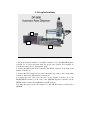
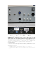
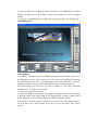
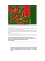
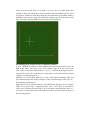
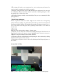
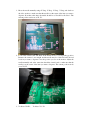
DP2600 Automatic Solder Paste Dispenser
User’s Manual
SMT MAX
125 Business Center Drive
Unit G
Corona, CA92880
(951)278-0720
http://www.SMTmax.com
DP2600
Thanks for purchasing our DP2600 automatic solder paste dispenser. The DP2600 is built
on a precise, heavy duty, general purpose XYZ movement table, driven by stepper motors.
In addition to the dispensing capability, additional tools can be mounted on it
conveniently.
NOTES and WARNINGS
1) Turn on the machine before starting the software.
2) All units displayed in the software are stepper motor steps, not measured distance.
3) Do not put any item on the machine platform which may block the movement of the
dispensing needle.
4) Do not put your fingers directly under the dispensing needle.
5) Immediately press down the red emergency button or turn off the machine power on
the machine control box if the machine is not working properly.
6) The machine will not work if the emergency button is in the pressed down position.
7) Please save the custom shipping crate for warranty returns.
1. Set up Instructions
3
2
1
1) Set up the dispenser machine (1), machine controller box (2), and QK982B dispenser
controller (3) on a flat and stable table. Set up the video monitor and computer on
convenient locations close to the dispenser group.
2) Connect the RS232 cable from computer to the RS232 connector on the back of the
machine controller (2).
3) Connect the X,Y,Z stepper motor cables, emergency stop cable to the corresponding
connectors on the back of the machine controller (2).
4) Connect the relay cable from the back of the machine controller (2) to the
FOOTSWITCH connector on the back of the QK982B dispenser controller. Set the
SETUP switches on the back of QK982B to all OFF positions.
5) Connect the air hose from a air compressor to the AIR IN connector on the back of
QK982B.
Back of the machine control box
Back of the QK982 paste dispenser controller
2. Computer Software Installation and Interface
The DP2600 software was developed and tested on Windows XP, not tested on any other
operating systems. The software should be installed on a computer which does not have
other applications which may interfere with the operation of the DP2600. Auto back up or
update should be disabled or scheduled to not overlay in time with the DP2600. Network
connection is not recommended, or plug the network cable only when it is used.
1. Install the software:
1). Create a new fold on your computer, name it to whatever you like. There are only two
files included in the software:
a). DP2600.exe, this is the actually program. Copy it to your working fold.
b). DeskWinAPI.dll. Copy it to either the working fold or the C:/windows/system32
fold.
2). Create a shortcut by clicking the left mouse button on the DP2600 icon, and then
clicking the right mouse button. Drag and place the shortcut icon on the computer
desktop.
3). Copy any other PCB Gerber files, dispensing or placing list files to the working fold.
2. DP2600 Interface
Control Buttons:
1). LoadPCB: click this button to load a PCB file in Gerber format. The file can be any of
the different layers: top, bottom, ground, power, silk screen, paste, solder mask, drill draw,
etc. Some files take less time to open and display, while others may take a long time.
Generally speaking, solder paste files should be used for paste dispensing purpose.
Note: The software now works only on positive coordinates, i.e., the origin of the PCB
design has to be set at the lower left corner.
2). About: shows the software version.
3). Center: If a PCB file is loaded into the program, clicking this button scales the display
to fit in the center of the display window. If a dispensing list is loaded, it centers the X
and Y sliding bars. It does nothing if there are no PCB or dispensing list files.
4). Zoom In: zooms in the display. Zoom in is based on the center of the display window.
5). Zoom Out: zooms out the display. Zoom out is based on the center of the display
window.
6). Step Sizes: stepper motor steps to move the dispensing needle.
7). +X, -X, +Y, -Y, +Z, -Z: move the dispensing needle in positive or negative directions
in steps specified in 6).
8). Home: moves the dispensing needle to machine home position. All the X,Y and Z
home switches are in closed status after homing.
9). Load Offset: loads an offset file into the program. Offset files specify the relative
location of the PCB board on the platform. Different offset files can be saved for different
PCB boards.
10). Save Offset: saves an offset file.
11). Z Limit: specifies the max. length the dispensing needle can go down. This value can
be changed by directly typing in another number. Set its value just a little greater than the
necessary downward travel distance. This prevents accidentally bends the needle.
12). COM1, COM2: RS232 communication port status. The program uses COM1 by
default. It can be changed by checking the COM2 radio button.
13). Needle Height:
• The first number shows the set position when the needle travels down. Dispensing is
preformed at this level. Clicking the Down button moves the needle to the down
position. Check the Needle Low Pos. box and click +Z or –Z to adjust this
position.
• The second number shows the up position. This position is useful only when in
continuous dispensing mode. The needle raises to this level, instead of going all
the way up to the machine up limit. Clicking the Up button moves the needle to
the up position. Check the Needle Up Pos. box and click +Z or –Z to adjust this
position.
• Note: The software will issue a warning message if the down position is greater than
the Z Limit. Fist enter a greater Z Limit value, then adjust this position.
• Both the Down and Up positions can be changed by directly typing in different
values.
14). PCB Offset:
• The X and Y values show the current offset, from the machine home position.
• Go Offset: click on this button moves the dispensing needle to the offset.
• Adj. Offset: check this box and click +X, -X, +Y and –Y to adjust the offset.
• Set Current: click this button to set the offset to the current needle position.
15). Dispensing Controls:
• Machine On: click on anywhere on the display window will move the needle to that
location if this box is checked.
• Dispenser On: controls immediate dispensing.
• Continuous: adding new items to the dispensing list continuously.
• Dispensing Spd.: dispensing speed. It controls the overall dispensing speed. The
smaller of this number, the slower.
• Dot Size: controls dispensing dot size. The smaller of this number, the smaller of the
dot size. This number actually controls how long the needle stays in the down
position while the compressed air is applied to the solder paste syringe.
• Go Home/Every Run: the needle goes to the machine home position after it finishes
a dispensing list, or starts a new one. Uncheck this box to disable this function.
• Interactive Disp.: runs a dispensing list by selecting the start item, end item, steps
between each stop.
• Run Dispensing: dispenses a complete list.
• Display List: click this button to open the dispensing list window.
16). Current Position: shows the current needle position.
3. Operations
1. Turn on the machine power on the back of the machine control box.
2. Start the DP2600 program by double-clicking on the DP2600 icon with the left mouse
button.
The machine should perform a home operation if all connections are good. It will issue a
“Serial port COM 1 not initialized” error message if the RS232 cable is not plugged in, or
if the machine control box is not powered on.
Note: if this is the first time you use the machine, do not mount the solder paste syringe
yet at this time. Get familiar with the software and the machine before doing that.
Click on the Zoom Out button, a rectangle in red color shows up. This is the valid
machine working area. The numbers show the machine steps the machine travels to the X
and Y limits. A white dot inside the working area shows the Offset point. This normally is
the PCB board lower left corner. Two white lines reaching to the X and Y limits specify
the position that a rectangle PCB board can be placed on the platform.
The following steps do not need to be performed in sequence:
3. Load a PCB file by clicking on the LoadPCB button. The display window shows the
PCB design, with a scale ration of 1:1, and coordinate origin at the lower left corner.
Click on the Center button if the PCB is too big or too small inside the display window.
Or use the Zoom In or Zoom Out buttons to check details, and use horizontal and vertical
sliding bars to adjust the view area.
Different colors in the PCB graph does not have actual physical meanings. They just
show different shapes, like circles, rectangles, round cornered rectangles, lines, texts, etc.
4. Generating a dispensing list
Dispensing list can be generated directly on the PCB design displayed on the computer.
There are two major types of dispensing items: lines or dots. They are generated in
similar ways. Click the left mouse button on a point where a dispensing lines starts, or a
dot needs to be placed, then click on the right mouse button, a selection window shows as
the following pictures:
Selecting the Start Dispensing to start a solder paste line, or selection Dot to dispense a
dot at the current location.
If the Start Dispensing is selected, a red circle shows at the current location with a gray
line connected from the red circle to the current mouse location. The gray lines moves
with the mouse.
Click the left mouse button at the dispensing stop location. The selection window shows
up again. Select the Stop Dispensing option to complete a dispensing line. Another small
window pops up:
This small window also shows up if Dot is selected at the dispensing start location.
Click Ok to add this new generated dispensing item to the list, or Cancel to discard it. The
Dispensing List window shows up at this time.
The dispensing list can be edited, saved or opened in the Dispensing List window. The
list shows the dispensing start and stop locations, line or dot, dot size, and more
information. The edit boxes below the list correspond to the highlighted item in the list.
Double click on a dispensing item, or type in the sequence number in the first edit box, to
show the data in the edit boxes. The corresponding values can be changed by directly
entering new values in the edit boxes.
The X-Offset, Y-Offset and Z-Offset values are not used now. Will be added later if
necessary. The Dot Size value specifies the dot size for the current item.
Control buttons in the Placing Parts List window:
• Open: opens and loads a saved list.
• Save: saves a list.
• Delete: deletes the currently selected item.
• Clr List: clears the entire list. The saved list will not be affected.
• UpdateDisplay: updates the display window.
• Go To Item: moves the dispensing needle to the selected item.
• Dispense Item: performs dispensing for the selected item.
The dispensing list can also be created continuously if the Continuous box is checked:
• Click the left mouse button on a dispensing start location:
• Click the right mouse button and select Dot to add a dispensing dot, or Cancel to
discontinue.
• Or drag the mouse to another location and click the left mouse button again to add a
dispensing line.
5. Syringe Mounting
After getting familiar with the machine and software, a syringe can be mounted to test the
real work.
The syringe should be mounted when the Z direction is at the down position. Click the
Down button in the needle height group to do this. Find a piece of thick paper (like an
airline ticket) or a thin credit card, place it on the circuit board; hold the syringe with the
needle to be used on it; tight the screws on the syringe mounting adapter. Do not tight too
much. It is better that the syringe can still move up and down in trials. This can save you
a few bent needles.
The circuit board should be placed on the platform parallel to both the X and Y axis.
Circuit board position can be fixed simply by using some screws attached to the
pre-drilled holes on the platform. The circuit board should be placed as close to the
machine home position as possible to prevent unnecessary machine travels.
Load the Gerber file into the program. Click with the left mouse button on some specific
points, and check if the needle moves to corresponding positions on the board.
Click on a specific point on the computer display.
Check on the video monitor if the needle moves to the corresponding position on the
circuit board. If not, adjust the Offset with the +X, -X, +Y, or –Y buttons while the Adj.
Offset box is checked. Uncheck the Adj. Offset box after adjusting the offset.
6. Paste Dispenser Options
1) The paste dispenser has the following settings that effect its operation
a) The compressed air regulator setting on your air compressor.
b) Pressure setting on the front panel of the QK982B paste dispenser that
determines the amount of force applied to the paste syringe.
c) The regulator setting for the the "pull back" (to prevent drip) vacuum, also
found on the front panel of QK982B. The vacuum setting can be minimum for
solder paste dispensing.
d) Dispensing speed which is set by the value of the Dispensing Spd on the
software for lines, or by the value of Dot Size for dots.
e) Needle size.
f) Solder paste grade.
2) The settings will require some experimentation to arrive at the proper performance, but
once found and documented they should be repeatable.
3) The paste syringe should be stored in the refrigerator(not the freezer) if it is not used
for a while(days). Place it in vertical direction to prevent air bubbles getting into it. Use
the supplied cap to seal the front outlet.
4) Self refilled syringes normally contain air bubbles. They are not recommended for fine
pitch applications.
7. Needle Height Adjustment
Besides air pressure, needle size, needle height are also critical factors in dispensing
quality. Generally speaking, the distance from the needle tip to the circuit board should
equal the needle inner diameter. The needle will smear the new dispensed paste if it is too
close to the circuit board. The paste will be pulled up if the needle is too far from the
circuit board.
8. Dispensing
There are several options in the software to dispense paste.
1). Dispense only one item: this is achieved by clicking the Dispense Item button in the
Dispensing List window. It dispenses only the highlighted item. It may be necessary to
redispense some points if they are missed in the first time.
2). Dispensing selected sequential items in the dispensing list: this is achieved by clicking
the Interactive Disp button on the software.
3). Dispensing a complete list: this is achieved by clicking the Run Dispensing button on
the software.
DP2600 NEW SYSTEM:
Note: if you do not have or do not want to use PCB file, you can do as following steps:
1. Move the needle manually using +X Step, -X Step, +Y Step, -Y Step, and check on
the video monitor to make sure that the needle is at the center of the item you want to
dispense. Note that at this time, the needle should be at “Needle Low Position”. The
current position can be set as X1, Y1.
2. Look at the circuit board and check if the needle moves to corresponding position.
Because the camera is not straight and the needle may be a little bit bend, the real
location you want to dispense is not the position you see on the monitor. Adjust the
needle manually and at the same time check the circuit board to make sure that the
needle is at the center of the item you want to dispense. The current position can be
set as X2, Y2.
3. X-offset = X2-X1;
Y-offset = Y2 –Y1
4. Now, you can add a new item to you dispensing list. Look at the video monitor, Move
the needle manually using +X Step, -X Step, +Y Step, -Y Step and make sure that it is
located at the center of the item you want to dispense. If you want to dispense a dot
you can get the value of current position (X, Y) first. and then set Start X, Stop X as X,
Set Start Y, Stop Y as Y. also you need to set X-offset and Y-offset( we have already
calculated these two value at step 3). If you want to dispense a line, you need to get
the values of Start X, Stop X, Start Y and Stop Y. And use the same X-offset and
Y-offset value which we have already calculated.
4. Troubleshooting
1. If the machine does not move at all: check RS232 serial cable connection, power
supply to the machine control box, stepper motor cables.
Also, the RED emergency button should be in the UP position. The machine will not
move if this button is pushed down.
2. Home positioning problems: check if X, Y and Z home switches are working correctly.
The Y home switch can be found under the platform.
3. No paste coming out of the needle:
a). Check if the needle is clogged.
b). Try a bigger needle.
c). Check air pressure on the air compressor and QK982B dispenser controller. Higher air
pressure can be used in the beginning and adjust it smaller once paste comes out
smoothly.
4. Contact us for technical support.
Contact:
SMT MAX
125 Business Center Drive, Unit G
Corona, CA92880
USA
Phone: (951)278-0720
Email: [email protected]
Web: http://www.SMTmax.com


![PCR-258-Tip Kit Manual [110125]](http://vs1.manualzilla.com/store/data/005777628_1-f6da4e9104aae97408b67d66533e329f-150x150.png)