1
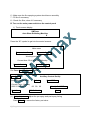
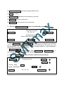
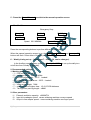
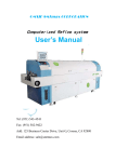
AE-250DS
Automatic Wave Soldering
Machine
User’s Manual
Omxie/SMTmax Corp.
www.smtmax.com
Copyright
1|Page
© 2006
Index of Content
1. Specifications
2. Power Supply
3. Operations
4. Maintenance
5. Warnings
6. Wave Soldering Techniques
7. Contact/Technical Support
2|Page
1. Specifications
1. Features
1. Applications:
(1)The AE-250DS wave soldering machine can be used for through hole
electronics assembling. The AE-250DS is a new design, easy to operate and maintain.
(2)It can be used either leaded or lead free assembling.
2. Preheating
(1)Preheating and filtration zone is designed as a module.
(2)Appliction of high-efficiency hot air circulation preheater.
(3)Heating elements have extended life, and easy to be replaced.
3. Flux spraying system
(1) Intelligent auto-tracking spraying system
(2) Auto speed adjustment
(3) Self-cleaning, no manual cleaning necessary
(4) Spray filters installed
4. Conveyor
(1)Rail conveyor system for smooth PCB transportation
(2)Closed loop conveyor speed adjustment
(3)Titanium clips for solder free operation
(4)Step-less height adjustment
(5)Loading board moves at the same speed
5. Soldering pot
(1)External heated soldering pot for reduced solder spills and oxidization
(2)Soldering pot easy cleaning
6. Control system
(1)Overheat warning. All motors have overload protection
(2)Mitsubishi PLC controllers are used, easy operation and high reliability.
(3)Optimized temperature sensing and controlling programs
3|Page
2. Specifications
Max. PCB width
PCB conveyor height
PCB conveyor speed
Preheating length
Preheating zones
Preheating Temperature
Suitable solders
Preheating power
Wave solder pot power
Solder pot capacity
Solder pot temperature
Temperature control
Flux storage tank
Power supply
Warm up power
Operation power
Air supply
Weight
Temperature
Shelf Dimensions
Equipment Dimensions
250mm
760±10mm
0~1.8m/min
800mm
1
room~200℃
Leaded, lead free
4.5KW
6KW
200KG
room~300℃
PLC
Max 5.2L
3 phase/5 wires, 380V or
220V
12KW
5KW
2
4-7kg/cm 12.5L/min
500kg
±2℃
L2000*W1000*H1600 (mm)
L2500*W1000*H1600 (mm)
3. Structure
A. Main parts
1. Frame;
2. Conveyor system: goes through flux spray, preheat, soldering pot and
cooling. PCB width adjustable
3. Flux spraying: to clean the PCB
4. Preheat: to dry the PCB and flux, reduce heat shock when it goes through the
soldering pot
5. Soldering pot: solder the PCB with the solder wave
6. Cooling: cooling with natural or refrigerated air
7. Controls: Optional PLC, computer controls
B. Modules
1. The machine has a front door, the electrical control box is under the front
door. The front door can be opened to inspect the inside.
2. The machine also has a back door, which can be opened to add flux, adjust
soldering pot height, adjust PCB forwarding angle, and change wave shape.
4|Page
3. The control panels are located at the front. The main LCD control panel is at
the upper left corner, which can be used to set up the operation of the
machine, including machine time, preheat and soldering pot temperatures
and ON/OFF of the machine.
4. The wave height and conveyor speed control panels are at the front upper
right corner.
5. The spray control panel is located at the back, which can be accessed by
opening the back door. Three separate air regulators can be used to adjust
the spray volume, spray press and spray movement cylinder frequency.
C. Transportation system
1. The transportation system is driven by a special motor with chain attached to
it. PCB clips are connected on the chain to fix PCB’s. A input adaptor board is
mounted at the input side.
D. Heating
1. Preheating: preheat is infrared
2. Soldering pot: external heating mode. Both straight and U shaped heating
elements are mounted on the outside of the soldering pot. Heat is transferred
through the walls of the soldering pot.
2. Power supply
Three phases/5 wires, 380/220V AC.
3. Operations
1. Operation
A. Get ready
1)Check loosed or shorted connections
2)Check if the conveyor is clean of objects which may prevent its movement
3)Check if the preheat area is clean, without obstacles
2
4)Check compressed air 4-7kg/cm
5) Check power supply connections, ground connection should be≤10Ω
5|Page
6)Make sure the flux spraying system should move smoothly
7)Fill flux if necessary
8)Check flux filter, clean it if necessary
B. Turn on the main power switch on the control panel
1) Touch screen display
SMTmax
Auto Wave Soldering Machine
▼
Press the “▼” symbol to get into the control screens.
Main menu
Temperature Control
Automatic Control
Working normally
Current time: 00 H 00 M 00 S Monday
Manual Control
▲
Auxiliary Control
2)
) Press Auxiliary Control button:
Auto Control
Auxiliary Control Set Up
Spray Adjustment ####
Default
Current Time:Monday
0000 Y 00 M 00 D
Main Menu
Shut Off Timer
00:00:00
30S Calibration
Weekly On/Off Time
Clock
(1). Spray Adjustment Adjust the pre-spray and post-spray timing
Press Default to restore the factory set value
6|Page
(2) Weekly On/Off Time: set up the weekly ON/OFF time
(3) Clock time set up
(4) 30S Calibration calibrate the current time to seconds
(5) Main Menu returns to main menu
(6) Auto Control Enter into auto set up sub-menu
3) Press the Temperature Control button in the Main Menu screen.
Temperature Control
00:00:00
Preheat Off
Soldering Pot Off
Temperature too low
Current Time: 00 H 00 M 00 S Monday
Auto Control
Main Menu
Manual Control
Press Preheat Off and Soldering Pot Off buttons to turn the preheat and soldering
pot on, set up the desired temperature; preheat and soldering pot will warm up to the
set temperature; the low temperature warning message pops up if the temperature
drops to the low boundary temperature:
Temperature too low
When the Ready message pops up, press Auto Control or Manual Control, to
switch to the Auto sub menu or Manual sub menu.
4) Press the Auto Control button, the Auto control screen shows up:
Auto Control
Emergency Stop
High wave
Low Wave
Counter:0000
Reset
Speed:##.# M/MIN
Auto Stop
7|Page
00:00:00
Transport
Auxiliary Set up
5)Press the Manual Control to switch to the manual operation screen
00:00:00
Emergency Stop
Spray Off
Shift Left
High Wave
Fine Wave
Shift Right
Conveyor Off
Speed:00.0 MM/Min
Manual Operation Off
Press the corresponding buttons to perform different operations:
When the manual operation screen is up, the High Wave Fine Wave and Conveyor Off
buttons will flash. Press either of them to perform the required operation.
6) Weekly timing set up (factory set 7:00-22:30, can be changed)。
In the Auxiliary control screen, press the Weekly On/Off Tim to set up the daily turn
on/off time from Sunday to Saturday.
2. Recommended settings:
1. Working parameters:
(1) PCB move angle:4~6°
(2) conveyor speed:0.9~1.3 M/Min.
(3) preheat temperature:150 °C (leaded)
(4) soldering pot temperature:250°C (leaded)
(5) flux: no clean
(6) solder wave height:7MM
(7) solder should be higher than:1/2~2/3 PCB thickness
(8) Through hole part leg length:≤4MM
2. Other parameters:
3
(1) External ventilation capacity:≥2000M /H
(2) Input in-line adaptor speed:≤wave soldering machine conveyor speed
(3) Output in-line adaptor speed:≥wave soldering machine conveyor speed
8|Page
5. Maintenance
1. Check conveyor transportation system and lubrication
(1) Gears of the input and output mechanism, and the PCB width adjustment
should be lubricated at least once in two months with high quality grease.
(2) The stainless steel pipes on the PCB width adjustment system should be
clean, and lubricated once in two weeks with high temperature grease.
(3) Transportation and width adjustment chains should be lubricated weekly
(4) The ball bearing on the wave soldering generator propeller should be
lubricated with high temperature grease weekly
2. Make sure no loose parts on the transportation system
(1) Check if the hex nut is tight on the transportation motor mounting, locking
mechanism should work properly;
(2) Reception board on the input side should be securely mounted;
(3) Check all bolts, nuts and screws are tight on the input side;
(4) Check if the transportation rail is parallel
3. Check if the PCB clips are in good working condition
(1) PCB clips can be taken off to adjusted
(2) Make sure the spring on the PCB clip works properly
4. Check the preheat zone, make sure no strange objects, dust, and flux residue.
(1) The preheat zone should be cleaned at least once a month; keep it clean all
the time
(2) Take off the screen steel board; please check if there are objects fall in, and
clean if necessary
5. Check flux filter and clean flux residues
(1) The flux filter should be cleaned at least once in two weeks, with warm water
(2) Keep the flux ventilation clean
6. Make sure the spray nozzle is clean and working properly; Make the spray
moves smoothly.
(1) Spray nozzle cleaning:
• Nozzle daily clean: the spray nozzle should be cleaned daily:fill the small flux
bucket with alcohol, turn its valve on and turn the valve from the bigger flux
bucket off, spray for 5~10 minutes.
• Weekly cleaning: take the spray nozzle off and for two hours, and rinse with clean
water.
9|Page
7. Check soldering pot for oxidization and residues
(1) To reduce the soldering pot oxidization, bean oil, anti-oxidization chemical or
alloy can be added into the pot
(2) The soldering pot should be inspected every hour. Oxidization residues
should be cleaned at that time
8. Check if the wave is smooth. The soldering pot should be cleaned completely
in every 200 hours.
(1) If too much residue accumulate in inside the solder wave channel, it may
affect shape of the wave, bubbles in the soldering pot, and also may cause
the motor to stop
(2) Remove the wave outlet and clean out the oxidization residues near it by
loose the mounting screws.
(3) All the solder in the solder pot should be replaced after a few months. The
metal alloy degrades after long time of use.
9. Check if the PCB clips cleaning pot has enough clean water. The water should
be replaced every week. Do not turn on the clips cleaning motor if there is no water in
the pot.
10. Check if the flux hose has holes
11. Check if the oil sprayer has enough oil. Add if necessary.
12. Keep the machine clean all the time.
6. Warnings
1. Do not let flux get into the preheating zone and soldering pot
2. Do not let flux get on high temperature area and electronic circuits
3. Do not turn on the soldering pot if there is no solder in it
4. Make sure the machine has good ground connection
5. Make sure the solder level is 20mm below the edge of the soldering pot, and 40mm
above the bottom. The best time to add solder is when the machine just turned on in the
morning. Try not to add solder when the machine is about to be turned off. Otherwise
the solder will spoil the next time the machine is turned on.
6. Do not touch the soldering pot, preheat zone and other high temperature areas when
the machine is on
7. Turn off the heat before releasing the used solder; remember to close the solder
release valve.
8. The emergency stop button should be used if accident happens
9. Keep the control box(with electronic circuits) clean to prevent electrical accidents
10. Slowly adjust the wave height, from low to high. Do not set the wave too high to get
out of the soldering pot
10 | P a g e
11. Do not let unrelated persons touching the control panel to prevent series personal
accidents and machine damages
7. Wave Soldering Techniques
Most problems in wave soldering are: false soldering, bad soldering shape, bridge,
stretching spike, holes, explosion, broken, black color and small balls.
1. False soldering
The soldering point looks dull or has small balls. Main causes:
1、Soldering pot temperature too low or too high
2、Conveyor moving too fast, or too slow
3、Component itself difficult to solder
2. No touch or too much touch
This happens when the component has a large metal area
No touch: metal surface has broken solder lines
Thin solder layer: solder does not have contact with the metal at all
Too much touch: wave too high and too much solder get on the metal
Causes:
1.
The component itself cannot be soldered
2.
Flux not good enough or expired
3.
Component surface too dirty
4.
Wave soldering time or temperature set up error
5.
Solder too old
3. Loose soldering
1.
Solder does not have good and enough contact at the soldering temperature
2.
PCB or component shakes during cooling period
3.
Component leg has bad preprocess
4. Too much or too little solder
1.
Too much solder on the soldering point, covers the component leg completely
2.
Not enough solder in the pot
3.
PCB pad oxidized or PCB has uneven surface
4.
Bad PCB soldering pad. Too big soldering pads, too thin component leg or
wire for the pad, etc.
5.
Soldering pad not co-center with the drill, conveyor moving too fast,
component leg too thin
5. Holes
Main reason is the solder does not fill the drill completely.
Causes
1.
Drill hole too big for the component leg
2.
Drill hole off center
3.
Broken soldering pad
4.
Drill hole oxidized, or has strange objects around it
5.
Component leg or wire too dirty, oxidized or bad preprocessing
11 | P a g e
6.
Bad PCB manufacturing
6. Bubbles
Small bubbles on the soldering point
1.
Too much flux, or the flux not completely evaporated when the PCB reaches
the soldering pot
2.
Workshop too much humidity, or residues left from PCB manufacturing
3.
Solder in the pot has air bubbles, or PCB itself carries air bubbles because of
dirty surface, oil, and other reasons
4.
Component leg too big for the drill hole
7. Rough soldering point
Rough soldering point looks rough and uneven on the surface. This is mostly
caused by shaking of the PCB in the cooling period.
8. Dull or sandy soldering point
The soldering point looks dull and gray, sometimes also sandy.
Causes:
1.
Solder too old, needs to be replaced
2.
Not enough tin in the solder
3.
Bad flux, flux stayed on soldering pad too, the bad gets eroded
4.
Too much anti-oxidization oil in the solder
5.
Too high soldering pot temperature
9. Cooling
Small cracks on the soldering point
1.
Soldering pot temperature not high enough
2.
Conveyor moves too fast, not enough soldering contact time
3.
PCB design problem
10. Stretched sharp point
1.
Too small PCB angle, best at 6°-7°
2.
Too much metal inside the solder mix
3.
Temperature, conveyor speed, and flux density all needs to be adjusted
11. Bridges
This is the most common and most complicated problem in wave soldering
Solutions:
1.
Solder quality
2.
Adjust conveyor moving speed when the PCB reaches the wave
3.
Check for PCB soldering pads clearance
4.
Dirty PCB surface
5.
Solder expired or contaminated
6.
Check flux freshness, and density
7.
PCB itself has very uneven heat property
8.
Component legs to long out of the drill holes
9.
PCB moving speed, and angle
12 | P a g e
8. Contact/ Technical Support
For more information or technical support please see below for contact.
SMTmax/ Omxie Corporation
125 Business Center Drive Unit G
Corona, CA 92880 USA
Tel: (951) 543-4543 Fax: (951) 582-9422
Email: [email protected]
13 | P a g e