1
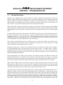
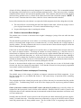
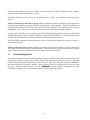
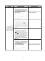
SERVICE MANUAL
McDonald’s SinBaD Series
SINGLE BASKET DISPENSER
FOR YOUR SAFETY
Do not store or use gasoline or other
flammable liquids and vapors in the
vicinity of this or any other appliance.
This document is to be inserted
into the Non-Fryer Section of
the Equipment Manual.
MANUFACTURED FOR
McDONALD’S®
BY FRYMASTER, L.L.C.
P.O. BOX 51000
SHREVEPORT, LOUISIANA 71135-1000
PHONE 1 (318) 865-1711
1 (800) 24 FRYER
TABLE OF CONTENTS
WARRANTY STATEMENT .................................................................................................................... Page i
TROUBLESHOOTING.............................................................................................................................Page 1-1
COMPONENT REPLACEMENT .............................................................................................................Page 2-1
PARTS LIST ............................................................................................................................................Page 3-1
APPENDIX A .......................................................................................................................................... Page A-1
Frymaster L.L.C., 8700 Line Avenue 71106, 5489 Campus Drive 71129
P.O. Box 51000, Shreveport, Louisiana 71135-1000
TEL 318-865-1711 FAX (Parts) 318-219-7140 (Tech Support) 318-219-7135
Printed in the United States
Service Hotline
1-800-24-FRYER
AUGUST 2004
U.S. $7.00
8195862
xx
DANGER
IMPROPER INSTALLATION, ADJUSTMENT, ALTERATION, SERVICE OR MAINTENANCE CAN CAUSE PROPERTY
DAMAGE, INJURY, OR DEATH. READ THE INSTALLATION, OPERATING, AND MAINTENANCE INSTRUCTIONS
THOROUGHLY BEFORE INSTALLING, OPERATING, OR SERVICING THIS EQUIPMENT.
DANGER
DO NOT ATTEMPT TO REPAIR OR REPLACE ANY COMPONENT OF THIS EQUIPMENT UNLESS ALL POWER TO THE
EQUIPMENT HAS BEEN DISCONNECTED.
DANGER
FOR YOUR SAFETY, DO NOT STORE OR USE GASOLINE OR OTHER FLAMMABLE VAPORS AND LIQUIDS IN THE
VICINITY OF THIS OR ANY OTHER APPLIANCE.
DANGER
FRYMASTER EQUIPMENT IS MANUFACTURED FOR USE WITH THE TYPE VOLTAGE SPECIFIED ON THE EQUIPMENT
RATING PLATE. FOR PROPER ELECTRICAL INSTALLATION PROCEDURES IN THE UNITED STATES, REFER TO THE
LATEST EDITION OF THE NATIONAL ELECTRIC CODE (ANSI/N.F.P.A. NO 70). IN CANADA, REFER TO THE CANADIAN
ELECTRICAL CODE PART 1 (CSA-22.1.) FOR INSTALLATION IN COUNTRIES OTHER THAN THE UNITED STATES AND
CANADA, REFER TO THE NATIONAL CODE APPROPRIATE FOR THE COUNTRY IN WHICH THE EQUIPMENT IS BEING
INSTALLED.
WARNING
DO NOT OPERATE THIS EQUIPMENT UNLESS ALL SERVICE AND ACCESS PANELS ARE IN PLACE AND PROPERLY
SECURED.
WARNING
COMPUTERS
FCC
This device complies with Part 15 of the FCC rules. Operation is subject to the following two conditions: 1) This device may
not cause harmful interference, and 2) This device must accept any interference received, including interference that may
cause undesired operation. While this device is a verified Class A device, it has been shown to meet the Class B limits.
CANADA
This digital apparatus does not exceed the Class A or B limits for radio noise emissions as set out by the
ICES-003 standard of the Canadian Department of Communications.
Cet appareil numerique n’emet pas de bruits radioelectriques depassany les limites de classe a et b prescrites
dans la norme NMB-003 edictee par le ministre des communications du Canada.
HAZARD COMMUNICATION STANDARD (HCS) – WHEN THE PROCEDURES IN THIS MANUAL INCLUDE
THE USE OF CHEMICAL PRODUCTS, THE PRODUCTS WILL BE PRINTED IN BOLD FACE, FOLLOWED BY
THE ABBREVIATION HCS IN THE TEXT PORTION OF THE PROCEDURE.
SEE THE HAZARD
COMMUNICATION STANDARD (HCS) MANUAL FOR THE APPROPRIATE MATERIAL SAFETY DATA SHEET
(MSDS).
xx
McDonald’s SinBaD SINGLE BASKET DISPENSER
WARRANTY STATEMENT
Frymaster L.L.C. makes the following limited warranties to the original purchaser only for this equipment and
replacement parts:
Warranty Provisions
Frymaster L.L.C. warrants all components against defects in material and workmanship for a period
of one year.
All parts, with the exception of fuses, are warranted for one year after installation date of cabinet.
If any parts, except fuses, become defective during the first year after installation date, Frymaster will
also pay straight-time labor costs to replace the part, plus up to 100 miles/160 km of travel (50
miles/80 km each way).
Parts Return
All defective in-warranty parts must be returned to a Frymaster Factory Authorized Service Center
within 60 days for credit. After 60 days, no credit will be allowed.
Warranty Exclusions
This warranty does not cover equipment that has been damaged due to misuse, abuse, alteration, or
accident such as:
•
•
•
•
•
•
Improper or unauthorized repair;
Failure to follow proper installation instructions and/or scheduled maintenance procedures as prescribed in the manual shipped with the unit;
Improper maintenance;
Damage in shipment;
Abnormal use;
Removal, alteration, or obliteration of the rating plate.
This warranty also does not cover:
•
•
•
Transportation or travel over 100 miles/160 km (50 miles/80 km each way), or travel time over
two-hours;
Overtime or holiday charges;
Consequential damages (the cost of repairing or replacing other property that is damaged), loss of
time, profits, use or any other incidental damages of any kind.
There are no implied warranties of merchantability or fitness for any particular use or purpose. For
international warranty, the above paragraphs apply, except that the customer is responsible for freight and
duty charges.
i
xx
McDonald’s SinBaD SINGLE BASKET DISPENSER
CHAPTER 1: TROUBLESHOOTING
1.1
Functional Description
When the unit is plugged into an electrical outlet, line voltage is supplied to the transformer. Placing the
ON/OFF switch in the ON position supplies 24VAC to the motor interface board. The motor interface board
supplies 12VDC to the controller and 24VDC to the dispense motor and drum motor. The drum motor will
activate briefly as the computer in the controller “wakes up,” then motor logic circuits in the controller will
turn it back off. If closed, the dispensing chute door will open and remain open.
When the ON/OFF switch is placed in the ON position, the controller automatically enters the STANDBY
mode. When in the STANDBY mode, the batch weight selector switch circuits are disabled and the CLEAN
and PROGRAM circuits are enabled. No indicator LEDs are illuminated when the unit is in the STANDBY
mode.
Pressing the RUN switch places the controller in the RUN mode and causes the RUN mode indicator above
the switch to illuminate. Every time the unit is placed in the RUN mode, the controller will perform an
initialization process to “zero” the load cell. The dispensing chute door will open and remain open
throughout the process to ensure accuracy. When in the RUN mode, the batch weight selector switch circuits
are enabled and the CLEAN and PROGRAM circuits are disabled.
The load cell is an aluminum bar that acts as a bridge resistor. One end of the load cell is fixed. The load cell
arms, dispensing chute, and dispense motor are attached to the opposite end. Their weight causes a slight
distortion of the bar, which changes the bar’s resistance.
During the zeroing process, circuitry in the controller measures the resistance associated with the weight of
the empty dispensing chute, the dispense motor, and the load cell arms. It compares this to a factoryprogrammed resistance range and, if within the range, records this as the “zero” value. If the resistance is
outside of tolerance, the unit goes into a zero failure mode, signified by blinking of the RUN mode indicator
and the PROGRAM mode indicator.
During programming of the batch selector switches, the controller measures the difference between the
previously determined “zero” resistance and the resistance associated with the new weight. It records the
differential so that a batch weight always corresponds to the “zero” resistance plus the differential resistance,
not a specific resistance value. This avoids erratic batches caused by fluctuations in the “zero” weight.
When a batch weight selector is pressed, the controller activates the drum motor to transfer fries to the
dispensing chute. When the fries enter the chute, their weight further distorts the load cell, causing a change
in resistance. When the resistance is equal to the “zero” resistance plus the resistance differential associated
with the batch weight selector pressed, the controller signals the drum motor to stop.
A proximity sensor at the rear of the dispensing well senses when a basket has been inserted into the well. It
signals the controller, which in turn activates the dispense motor to dump the fries. When the door reaches
the full open position, a flag on the dispense motor shaft is detected by a Hall effect sensor that signals the
controller. The controller in turn reverses the current to the motor, closing the door. When the door reaches
the closed position, another Hall effect sensor detects the flag on the motor shaft and signals the controller.
The controller reduces power to the dispense motor to approximately 1VDC, causing the motor to hold the
door closed. A built-in 1½-second delay allows the load cell to stabilize before the controller reactivates the
1-1
drum motor to reload the dispensing chute. If a basket has been pre-positioned beneath the dispensing chute,
the unit will dispense the batch as soon as the load cell is satisfied and begin loading another batch. The
second batch will be held until the first batch is removed and a new basket is inserted. The process continues
until the unit is placed in the STANDBY mode or the ON/OFF switch is placed in the OFF position.
1.2
Troubleshooting and Problem Isolation
This section is intended to provide technicians with a general knowledge of the broad problem categories
associated with this equipment, and the probable causes of each.
Problems you are likely to encounter can be grouped into three categories:
a.
b.
c.
Failures to “zero”
Erratic or inaccurate batch weights
Failures to function correctly
A series of troubleshooting guides is also included at the end of the chapter to assist in identifying some of
the more common problems.
1.2.1
Failures to “Zero”
As discussed in Section 1.1, the unit determines batch weights by comparing the load cell resistance to a prerecorded resistance value equal to the empty or “zero” resistance value plus a resistance differential value
corresponding to a particular batch weight. When the load cell resistance is equal to the “zero” resistance
plus the resistance differential, the load cell is “satisfied” and the drum motor is stopped. Although each load
cell is theoretically identical, in actuality any given cell may have a slightly different resistance from any
other cell. Consequently, the cell must be “zeroed” to determine and record its actual resistance in order to
ensure accurate batch weights. The unit must be “zeroed” with the dispense chute in place, and no part of the
dispense chute may be in contact with the cabinet.
The load cell itself is basically an aluminum bar. When
not under stress, it has a particular resistance. When the
bar is vertically distorted by applying weight to one end,
the resistance changes. Also, if the bar contacts any
other component, such as the end of the dispense motor
shaft, its resistance will be changed, forcing it outside
the acceptable range. Circuitry within the controller
measures the load cell resistance and compares this to a
factory-programmed (and very narrow) range. As long
as the load cell resistance falls within this range, the unit
will “zero.”
The Load Cell Assembly
Load Cell
Load Cell Brace
Other than the load cell or an associated component being in contact with something it shouldn’t, there are
only three probable causes for failing to “zero.” The first is a malfunctioning controller. If the controller
cannot measure load cell resistance or loses the programmed resistance range, it cannot “zero.” The
recommended method of checking the controller is to use a load cell simulator (P/N 826-5658). If the unit
fails to zero with the simulator substituted for the load cell, the controller has probably failed. An alternate
method is to substitute a controller known to be good for the suspect controller. It is not necessary to install a
controller to test it. Simply plug the cabling into the new controller. If the unit “zeroes,” the controller in the
unit has failed and should be replaced with the new one. The next probable cause is a failed load cell.
Failure may be caused by bending of the cell or by damage to the cabling. Because the resistance range is
narrow, it is usually impossible to see the damage, so the appearance of the load cell is not a good indicator
1-2
of load cell failure, although an obviously damaged cell is immediately suspect. The recommended method
for diagnosing a failed load cell is to use the simulator mentioned earlier. If the unit zeroes with a simulator
substituted for the load cell, the load cell has probably failed. If the controller and load cell test OK, the third
(and least likely) probable cause is a failure of the cable between the load cell and the computer. NOTE: If
the unit “zeroes” sometimes but fails at others, check for a loose connection at the controller.
In any of the situations, the only solution is to replace the failed component, but before doing that verify that
a.
The load cell brace is not touching the end of the dispense motor shaft. (Do this by trying to insert a
piece of paper between the two. If it can be inserted without drag, it’s okay.)
b.
No part of the dispense chute is touching the cabinet.
1.2.2
Erratic or Inaccurate Batch Weights
The probable cause of erratic or inaccurate batch weights is bumping or jarring of the unit while the drum
motor is running.
The unit should be positioned in an area where it is not likely to be bumped or jarred during operation. If
erratic or inaccurate batch weights occur at random intervals, it is likely that the unit is being bumped or
jarred by workers. The only solutions in this case are to move the unit or better educate employees about the
effects of bumping the unit during operation.
If the erratic or inaccurate batch weights occur at specific times, or if the problem comes and goes, there may
be a source of unusual vibration. Two things to consider are facility location (e.g., is the store close to a
railroad track or a highway where trains or heavy trucks pass on a regular schedule) and unit location (e.g., is
it next to a heavy door that slams shut), etc. In the case of facility location not much can be done, although it
may be possible to dampen the vibrations by placing the unit on a rubber pad. In the case of unit location,
consider an alternate location for the unit. Avoid moving the unit long distances without the load cell shim in
place. Excessive jarring of the unit in movement may damage the load cell.
If erratic or inaccurate batch weights occur consistently, it is likely that one or more of the batch weight
selectors may have been improperly programmed. Verify that the selectors have been properly programmed
in accordance with the instructions in Appendix A.
1.2.3
Failures to Function and Improper Functioning
The probable causes of this category of problem are improper connections and failed components. If you
have not already done so, you should read Section 1.1 (the system theory of operation) before continuing
with this section.
The paragraphs that follow identify the general types of failures that may be encountered and the possible
causes of each. Troubleshooting Guides at the end of the chapter provide step-by-step problem-isolation
procedures.
Failure of the unit to initialize when ON/OFF switch is placed in ON position can be caused by failure of a
component in the input power circuit or failure of the controller. When the ON/OFF switch is placed in the
ON position the two error conditions that may be encountered are that the drum motor does not activate at all
or it runs continuously.
Normally when the ON/OFF switch is placed in the ON position, the drum motor briefly activates (approximately 2 seconds) then stops. If the drum motor runs continuously as soon as the ON/OFF switch is placed
in the ON position, there are three probable causes. The first is that 12VDC is not getting to the controller
1-3
from the motor interface board. The second is that the controller has failed. The third is that controller
signals are not reaching the motor drive circuits.
If the drum motor does not activate at all, the probable cause is failure of a component in the input power
circuit.
Failures of the dispense chute door to open or close are caused by problems with the Hall effect sensors, the
proximity sensor, the dispense motor, the motor interface board, or the controller. The primary indication of
a problem involving the “closed” Hall effect sensor (J8 on the controller) is the partial closing of the door
following the “zero” routine or the removal and replacement of a basket during normal operation.
A failed “open” Hall effect sensor (J8 on the controller) is indicated by the normal “zeroing” of the unit and
loading of the dispense chute, but failure of the door to open to dispense the fries. A failed proximity sensor
will give the same indication, so care must be taken to differentiate between the two.
If the Hall effect sensors have been ruled out as the cause of the failure to function, the most likely cause is a
motor-related problem.
Failures of the drum motor to start or stop are caused by problems in the controller, load cell, motor interface board, or drum motor and the associated wiring. If the motor fails to stop, the problem is not with the
motor. It may be with the controller, the load cell, or the motor interface board.
1.3
Troubleshooting Guides
The Troubleshooting Guides in the following pages provide a systematic method for isolating specific problems and the action(s) to take to correct them. When using the guides to isolate the cause of a particular
problem, begin with the first probable cause and work down. Also, don’t forget the Operator Troubleshooting Guides found in the Operator’s Manual. Most problems likely to be encountered are covered in these
two sets. However, don’t hesitate to call the Frymaster Technical Services Department at 1-80024-FRYER (1-800-243-7937) if you need assistance in solving a particular problem.
1-4
Problem
Probable Causes
A. Failed power cord.
Corrective Action
A. Replace the power cord.
Test: Check for line voltage on the
line side of the line filter. If not present, the power cord has failed.
B. Replace the line filter.
B. Failed line filter.
Test: Check for line voltage on the
line side of the filter and on the load
side. If line voltage is present on the
line side but not the load side, the filter has failed.
C. Replace the ON/OFF switch.
C. Failed ON/OFF switch.
Test: Check for line voltage on the
load side of the line filter and on the
transformer brown and blue wires. If
line voltage is present on the load side
of the filter but not on the transformer
brown and blue wires, the switch has
NO POWER WITH
failed.
UNIT VERIFIED TO BE
D. Replace the transformer.
PLUGGED IN AND D. Failed transformer.
CIRCUIT BREAKER
Test: Check for line voltage on the
VERIFIED TO BE ON.
transformer brown and blue wires
and 24VAC on the black and orange
wires and 12VAC on the black and
yellow wires. If line voltage is present on the transformer brown and blue
wires, and either of the other two
voltages is incorrect, the transformer
has failed.
E. Failed motor interface board.
E. Replace the motor interface board.
Test: Check for 12VDC on connector
J3 of the board. If voltage is incorrect, the board has failed.
F. Replace the 12VDC power cable.
F. Failed 12VDC power cable.
Test: Check for 12VDC on connector
J3 of the motor interface board. If
voltage is correct, the 12VDC power
cable has failed.
1-5
Problem
Probable Causes
A. Failed controller.
Test 1: If a load cell simulator is
available, disconnect the load cell
from the controller and connect the
simulator. Turn unit off then back on
using the ON/OFF switch. Press the
RUN switch. If the unit does not
zero, the controller has failed.
Corrective Action
A. Replace the controller.
NOTE: Before installing a new
controller, plug the cabling into the
new controller, turn the unit off
then back on using the ON/OFF
switch, and press the RUN switch.
If the unit zeroes, the diagnosis is
confirmed and the replacement
computer can then be installed. If
the unit still does not zero, the
problem is not with the controller.
Test 2: If a load cell simulator is not
available, turn unit off them back on
using the ON/OFF switch. Press the
RUN switch and look for the following conditions:
1. Drum motor activates briefly,
then stops.
2. Indicators in RUN switch and
PROGRAM switch do not flash.
If both conditions are true, the controller is suspect.
B. Replace the load cell.
B. Failed load cell.
UNIT WILL NOT
ZERO.
Test 1: If a load cell simulator is
available, disconnect the load cell
from the controller and connect the
simulator. Turn unit off then back on
using the ON/OFF switch. Press the
RUN switch. If the unit zeroes, the
load cell is suspect.
NOTE: Before replacing a load
cell, verify that a piece of paper can
be inserted between the dispense
motor shaft and the load cell brace.
If not, the load cell is out of alignment. Refer to Section 2.2.2 for
corrective action.
Test 2: If a load cell simulator is not
available, turn unit off then back on
using the ON/OFF switch. Press the
RUN switch and look for the following conditions:
1. Drum motor activates briefly,
then stops.
2. Indicators in RUN switch and
PROGRAM switch flash.
If both conditions are true, and a
piece of paper can be inserted between the dispense motor shaft and
the load cell brace, the load cell has
failed.
C. Loose or broken load cell cable.
C. If the cable is loose, reconnect it. If
the cable is broken, replace the load
Test: Check connection to verify that
cell.
the cable is securely plugged into
connector J3 on the controller.
1-6
Problem
Probable Causes
Corrective Action
A. Unit is located in an area where it is A. Relocate unit to an area where it is
being bumped or jarred during operaless likely to be bumped or jarred
tion.
during operation. Ensure unit is
not in contact with adjacent walls.
BATCH WEIGHTS
B. Unit is in an area subject to unusual B. The effect of environmental vibraARE INCONSISTENT
environmental vibration, such as adtions may be lessened by placing
OR INACCURATE.
jacent to a railroad track or near a
the unit on a thick mat.
major highway.
C. Batch weight selectors are incorrectly C. Reprogram batch weights in accorprogrammed.
dance with Appendix A.
D. Failed Test 1 – Replace the motor
A. 12VDC is not getting to the
interface board.
controller.
Test 1: Check for 12VDC at motor
interface board connector J3. If
voltage is not present, probable cause
is failure of the motor interface board.
If voltage is present, perform Test 2.
DRUM MOTOR RUNS
CONTINUOUSLY AS
SOON AS THE ON/OFF
SWITCH IS PLACED
IN THE ON POSITION.
Failed Test 2 – Replace the 12VDC
power cable.
Test 2: Check for 12VDC at the
controller end of the 12VDC cable. If
voltage is present on connector J3 but
not at controller end of the cable, the
cable has failed. If voltage is present
at the controller end of the cable the
controller is suspect. Go to B.
B. Failed controller.
E. Replace the controller.
Test: Substitute new controller for
suspect controller. Turn unit off and
back on using the ON/OFF switch.
Press RUN switch. If unit functions
correctly, the controller has failed.
A. Failed drum motor.
A. Replace the drum motor.
Test: With loading chute empty, turn
the unit off then back on using the
ON/OFF switch. Press the RUN–
switch. Check for 24VDC at motor
end of drum motor cable. If voltage is
DRUM MOTOR DOES
present, the drum motor has failed.
NOT ACTIVATE AT
B. Replace the motor interface board.
ALL. B. Failed motor interface board.
Test: Check for 24VAC at connector
J1 of the motor interface board. If
voltage is present and a motor known
to be good does not activate when
RUN switch is pressed, the motor interface board may have failed.
1-7
NOTE: Before replacing the
motor interface board, check the
continuity of the drum motor cable
to be sure it is not the problem.
Problem
Probable Causes
A. Failed dispense motor.
Corrective Action
A. Replace the dispense motor.
Test: Turn the unit off then back on
using the ON/OFF switch, then press
the RUN switch. Check the DOOR
LED for a bright red glow, and for
24-35VDC at the motor end of the
dispense motor cable. If both conditions are true, the dispense motor has
failed.
B. Failed dispense motor cable.
B. Replace the dispense motor cable.
Test: Check for 24-35VDC on connector J5 of the motor interface
board. If voltage is not present, the
dispense motor cable has failed.
C. Failed motor interface board.
DISPENSE CHUTE
DOOR DOES NOT
OPEN.
C. Replace the motor interface board.
Test: Check for 24-35VDC on connector J5 of the motor interface
board. If voltage is present, the motor
interface board has failed.
D. Failed proximity sensor.
D. Replace the proximity sensor.
Test: Place a basket into the dispensing well and check for illumination of the proximity sensor. If the
sensor is not illuminated, the sensor
has failed.
E. Failed/misaligned upper Hall effect E. Realign or replace the upper Hall
effect sensor as necessary.
sensor.
Test: If the unit zeroes and loads the
dispense chute normally, remove the
hopper and basket from the unit and
empty the dispense chute. Replace
the basket. If the drum motor does
not start, the upper Hall effect sensor
is out of alignment or has failed.
F. Failed controller.
F. Replace the controller.
Test: Disconnect the cables from the
suspect controller and connect them
to a controller known to be good.
Turn the unit off then back on using
the ON/OFF switch, the press the
RUN switch. If the unit operates correctly, the controller has failed.
1-8
Problem
Probable Causes
A. Failed dispense motor.
Corrective Action
A. Replace the dispense motor.
Test: Turn the unit off then back on
using the ON/OFF switch, then press
the RUN switch. After the unit zeroes, check for 24-35VDC on the
motor end of the dispense motor cable. If voltage is present, the dispense
motor has failed.
B. Replace the motor interface board
B. Failed motor interface board or
or dispense motor cable as redispense motor cable.
quired.
Test: Turn the unit off then back on
using the ON/OFF switch, then press
the RUN switch. After the unit zeroes, check for 24-35VDC on J5 of
the motor interface board. If voltage
DISPENSE CHUTE
is not present, the motor interface
DOOR DOES NOT
board has failed. If voltage is present,
CLOSE.
the dispense motor cable has failed.
C. Failed/misaligned lower Hall effect C. Realign or replace the lower Hall
sensor.
effect sensor as necessary.
Test: If the unit zeroes and the door
partially closes, the lower Hall effect
sensor is out of alignment or has
failed.
D. Failed controller.
D. Replace the controller.
Test: Disconnect the cables from the
suspect controller and connect them
to a controller known to be good.
Turn the unit off then back on using
the ON/OFF switch, the press the
RUN switch. If the unit operates correctly, the controller has failed.
1-9
1.4
Wiring Diagrams
1-10
LINE VOLTAGE
2
1
24V
LINE FILTER
1-11
12VDC
J2
2
2
2
1
1
4
3
2
1
J5
12VDC
PROCESSING CIRCUITS
AND TRACINGS
J3
LOAD CELL
DRUM
MOTOR
DISPENSE
MOTOR
3
2
R
1
PROXIMITY
SENSOR
LEDS
R/G
J8
6
5
DOOR OPEN
HALL EFFECT
SENSOR
24V
4
R
2
1
COMPUTER
3
DOOR CLOSED
HALL EFFECT
SENSOR
NOTE: PROXIMITY SENSOR AND HALL
EFFECT SENSORS SHOWN AS FUNCTIONAL
SWITCHES FOR SIMPLICITY. LOAD CELL
CIRCUITRY NOT ILLUSTRATED FOR SAME REASON.
SIMPLIFIED WIRING DIAGRAM
3
3
J4
2
1
BLACK
1
4
4
TO J5
FROM J2
WHITE
J1
5
5
TO J4
BOARD
TRACINGS
AND
24VDC
SOURCE
24VDC
J5
2
1
GREEN
J2
FUSE
(CE MODELS ONLY)
J3
J1
1
1
3
R/G
MOTOR INTERFACE BOARD
FROM J2
RED
805-1020A
1-12
McDonald’s SinBaD SINGLE BASKET DISPENSER
CHAPTER 2: COMPONENT REPLACEMENT
2.1
Accessing Components
The unit’s back panel must be removed to access all electronic components except the drum motor. The
panel is held in place by two hex-head screws located along the bottom edge. A separate access panel must
be removed to gain access to the drum motor. It is held in place with two hex-head screws. In order to access the ON/OFF switch and controller, the right cabinet top must also be removed. It is secured by two panhead machine screws and Keps nuts at the left rear corner (as viewed from the rear of the unit) and one hexhead screw at the right rear corner. The front of the panel is held in place by a pair of tabs that fit into slots
cut into the front of the cabinet. When the retaining screws have been removed, lift up on the rear and move
the cabinet top toward the front to disengage the tabs.
2.2
Replacing Components
2.2.1
Replacing the Controller
1. Disconnect the unit from the electrical power source.
2. Disconnect all cables from the jacks on the back of the controller. If the cables are not marked indicating
their jacks, mark the cables before disconnecting them.
3. The controller is held in place by four Keps nuts. Remove the nuts and pull the controller straight rearward off the mounting studs.
4. Reverse steps 1-3 to install new controller.
2.2.2
Replacing the Load Cell and Associated Components
1. Disconnect the unit from the electrical power source.
2. Disconnect the load cell cable from the back of the
controller (see photo below).
These components
shown separated from
cabinet to reveal load
cell arms.
Load Cell Cable
Load Cell Arms
Dispense
Chute
3. Remove the dispensing chute by lifting it up from the
load cell arms and carefully sliding it toward you
(see illustration at right).
2-1
4. Remove the two bolts securing the load cell arms to
the load cell (see illustration at right). Carefully
lower the load cell arms/dispense motor assembly to
the bottom of the dispense chamber.
5. Remove the two bolts securing the load cell/load cell
brace assembly to the load cell saddle (see illustration below) and remove the load cell and load cell
brace.
Remove
these
bolts
Load cell saddle
Remove
these
bolts
6. Reattach the replacement load cell and the load cell brace to the load cell saddle and securely tighten the
bolts. Verify that the gap between the load cell and stop screw in the load cell brace is approximately
.015 inch ± .005 inch (.4mm ± .13mm).
7. Reverse steps 1 through 4 to complete the procedure.
2.2.3
Replacing the Dispense Motor
1. Disconnect the unit from the electrical power source and remove the back panel to access wiring.
2. Disconnect the dispense motor wiring harness and Hall effect sensor cable (see photo below).
Hall Effect Sensor Cable
Dispense Motor Wiring Harness
2-2
3. Remove the basket alignment rack from the dispensing
well. Remove the two bolts securing the dispense motor to
the load cell arms (see illustration at right). Be ready to
support the approximate 6-pound/3-kilogram weight of the
dispense motor assembly when the bolts are removed.
Remove
these
bolts
4. Carefully pull the dispense motor assembly out through the
opening in the cabinet.
5. Remove the setscrew securing the dispense door arm to the
motor shaft and slip the arm from the shaft, being careful
not to lose the square key. Remove the four Keps nuts from
the screws securing the motor assembly to the dispense
motor bracket.
Remove
motor through
this opening
Dispense Door Arm
Inner Motor Stop
Mounting Bracket
Ground Wire
Tang
Outer Motor Stop
Square Key
Shim
Sensor Flag
Detail of Hall Effect Sensor Assembly and
Brackets (sensor wiring omitted for clarity)
Bracket with offset
goes on last.
Leave a 1/4-inch (6.25mm) gap between
edge of Dispense Arm and Inner Motor Stop.
6. Loosen the setscrew securing the sensor flag to the motor shaft and slide the flag and shim (spacer) from
the shaft.
7. Slip the Hall effect sensor brackets off the mounting screws and separate the motor and mounting
bracket.
8. Assemble the replacement motor to the bracket then replace the Hall effect sensor brackets, installing the
bracket with offset last (see illustration in step 5). Replace and tighten the four Keps nuts, torquing to
5-10 inches/pound. NOTE: Ensure the ground wire is reattached to the upper right hand mounting
screw.
9. Insert the square key into the groove in the long motor shaft, align the slot in the dispense arm hub with
the square key, and slip the arm onto the shaft with the hub on the outside (see illustration in step 5).
NOTE: The door must be positioned between the motor stops (rotate the shaft, if necessary) and there
must be at least 5⁄16-inch (8 mm) clearance between the door and the motor. Torque the setscrew to 20-25
inches/pound.
2-3
10. Slip the shim (spacer) onto the short motor shaft, followed by the sensor flag (with the hub facing the
shim). Rotate the dispense arm so that the tang is pointed up (see illustration in step 5) and there is a gap
of approximately ¼-inch (6.25 mm) between the edge and the inner motor stop.
11. Remove any slack in the motor shaft by placing the arm end on a work surface and gently pressing down
on the motor. At the same time, rotate the sensor flag so that it is positioned between the faces of the upper (left) Hall effect sensor. Verify that there is a gap of approximately ¼-inch (6.25 mm) between the
arm and the inner motor stop, then tighten the setscrew, torquing to 12 inches/pound.
12. Reinstall the dispense motor assembly by reversing steps 1 through 4.
2.2.4
Replacing the Drum Motor
1. Disconnect the unit from the electrical power source.
2. Disconnect the drum motor wiring from
the drum motor cable (see illustration at
right). NOTE: The drum motor cable
plugs into the motor interface board and
the motor wiring plugs into it. It is not
necessary to disconnect the drum motor
cable from the motor interface board.
3. Remove the four Keps nuts (see
illustration at right) that secure the drum
motor to the drum motor bracket and pull
the motor straight back off the mounting
screws.
4.
Grasp the motor shaft with a pair of
locking pliers and unscrew the rotator arm
(“bullet”) from the motor shaft and
transfer it to the new motor.
5.
Slip the new motor over the four
mounting screws, being careful not to
dislodge the screws. Replace and tighten
the Keps nuts.
6.
Reverse steps 1 and 2 to complete the procedure.
2.2.5
Remove
these
nuts
Disconnect
motor wiring
here
Replacing the Transformer or Line Filter
1. Disconnect the unit from the electrical power source.
2. Holding the new component next to the component being replaced, disconnect each wire from the old
component and connect it to the new component, one at a time.
3. Remove the screws securing the old component to the mounting bracket, remove the old component, and
install the new component.
4. Reconnect the unit to the electrical power source.
2-4
2.2.6
Replacing the Proximity Sensor
1. Disconnect the unit from the electrical power source.
2. Unplug the proximity sensor from the controller.
3. Unscrew the failed sensor from the block. Thread the stop nut on the replacement sensor back toward the
cord-end until approximately ½ inch (12.5mm) of threads remain. Carefully screw the replacement sensor into the Teflon block until it is finger tight. Tighten the stop nut against cabinet.
4. Plug the sensor cable into jack J5 on the controller and reconnect the unit to the electrical power source.
2.2.7
Replacing the Motor Interface Board
1.
Disconnect the unit from the electrical power source.
2.
Holding the new interface board next to the one being replaced, disconnect each cable from the failed
interface board and connect it to the new board, one at a time.
3.
Remove the four Keps nuts securing the old board to its mounting and slip it off the mounting studs, being careful not to dislodge the spacers behind the board. Slip the new board onto the mounting studs and
replace the Keps nuts.
4.
Reconnect the unit to the electrical power source.
2-5
xx
McDonald’s SinBaD SINGLE BASKET DISPENSERS
CHAPTER 3: PARTS LIST
ACCESSORIES
18
NOTES:
Item 13 may be
attached to either side of
Item 14.
11
6
Item 16 may be mounted
on either side of cabinet to
correspond to location of
Item 13.
19
12
14
10
4
16
8
9
13
2
1
17
15
7
5
3
ITEM
1
2
3
4
5
6
7
8
9
10
11
12
13
14
15
16
17
18
19
PART #
COMPONENT
900-2949 Shim, Caster
803-0276 Rack, Wire Basket Positioning
810-2220
Leg
809-0132
Screw, ¼-20 x ¾-inch Slotted Pan Head
826-1368
Nut, ¼-20 Serrated Flange (Pkg. of 10)
809-0747
Thumbscrew, ¼-30 x ⅜-inch
810-0378
Caster, 5-inch Wheel Rigid
810-2231
Block, Threaded
812-1496SP Hopper
816-0378
Drum
816-0491
Lid, Hopper
816-0568
Glass, Sight
823-3683
Arm, Basket Rack
823-3685
Rack, Basket
824-0893
Pan, Crumb
824-1022
Receiver, SinBaD Bracket
824-1023
Tray, Basket Rack
910-7920
Handle, Hopper Lid
910-8688
Deflector
3-1
CABINETRY
1
28
5
14
2
4
21
13
22
25
27
19
7
18
15
12
13
23
14
3
17
11
9
9
30
8
14
16
20
6
10
26
3-2
29
11
9
24
ITEM
1
2
3
4
5
6
7
8
9
10
11
12
13
14
15
16
17
18
19
20
21
22
23
24
25
26
27
28
29
30
PART #
106-0643
106-0777
106-1438
806-9228
806-9235
806-9782
807-1083
826-1680
826-1389
809-0189
809-0191
809-0194
809-0250
809-0434
809-0783
810-0356
810-0357
810-1644
823-2761
823-3191
823-3383
824-0752
824-0771
900-8208
900-8211
900-8223
900-8224
900-8324
900-8352
900-9440
COMPONENT
Cover Assembly, SinBaD Drum Motor
Side, Left Cabinet
Side, Right Cabinet
Cover, Right Cabinet Top
Cover, Left Cabinet Top
Base Assembly
Bushing, Nylon (fits 2-inch hole)
Clamp, Plastic Wire (Pkg. of 8)
Screw, ¼-20 x ¾-inch Hex Head (Pkg. of 10)
Washer, ¼-inch SAE Flat
Washer, ¼-inch Lock
Washer, 5⁄16-inch SAE Flat
Nut, 6-32 Keps Hex
Screw, #10 x ⅜-inch Hex Washer Head
Nut, 5⁄16-18 Hex Nylon Lock
Caster w/o Brake, 5-inch (for 3-inch caster, use 810-2508)
Caster w/Brake, 5-inch (for 3-inch caster, use 810-2509)
Guide, Basket
Panel, Cabinet Front
Liner, Cabinet Bottom
Liner, Cabinet Inner
Cover, Dispense Motor
Cover, SinBaD Load Cell
Cover, Back
Brace, Upper Back
Brace, Lower Back Right
Brace, Load Cell Vertical
Panel, Motor Access
Brace, Lower Back Left
Support, Base
3-3
7
25
26
22
4
9
16
14
31
6
6
8
3-4
24
13
21
19
18
1
32
20
3
33
30
11
29
15
27
28
23
5
10
17
12
2
DISPENSE SYSTEM COMPONENTS
ITEM
PART #
1
210-0810
2
806-8969SP
3
806-9258
4
806-9271
5
807-3004
6
826-1389
7
809-0171
8
809-0191
9
809-0193
10
826-1366
11
809-0247
12
809-0434
13
809-0480
14
809-0613
15
809-0649
16
809-0674
17
809-0675
18
809-0737
19
810-1391
20
810-1770
21
810-1771
22
816-0400
23
823-2607
24
823-2670
25
823-2717
26
823-3412
27
900-8169
28
900-8211
29
900-8233
30
910-5855
31
910-7950
32
910-8164
33
910-8165
*
826-1746
* Not illustrated.
COMPONENT
Stop, Door Open Position
Switch Assembly, Position (Hall Effect Sensor)
Load Cell Assembly
Load Cell Arm Assembly
Motor, 24VDC Dispense
Screw, ¼-20 x ¾-inch Hex Head (Pkg. of 10)
Thumbscrew, ¼-20 x 1⅜-inch
Washer, ¼-inch Lock
Washer, ¼-inch Nylon Flat
Nut, 4-40 Keps Hex (Pkg. of 25)
Nut, 8-32 Keps Hex
Screw, #10 x ⅜-inch Hex Washer Head
Setscrew, ¼-28 x 5⁄8-inch
Screw, 8-32 x 2-inch Fillister Head
Bolt, ¼-20 x 1½-inch
Setscrew, 8-32 x ⅜-inch Cup Point Square Head
Screw, 4-40 x ½-inch Slotted Pan Head
Screw, ¼-20 x ¼-inch Slotted Round Head Cap
Key, ⅛-inch x ¾-inch
Brace, Load Cell
Rod, ¼-inch x ⅜-inch Aluminum
Door, Dispense Chute
Flag, Door Position (Hall Effect Sensor Flag)
Arm, Dispense Door
Chute, Dispense
Top, Dispense Chute
Shim, Motor Shaft
Brace, Upper Back
Saddle, Load Cell
Bracket, Dispense Motor
Stop, Door Closed Position
Bracket, Lower Position Switch (Lower Hall Effect Sensor Bracket)
Bracket, Upper Position Switch (Upper Hall Effect Sensor Bracket)
Tester, Load Cell
3-5
DRUM MOTOR COMPONENTS
4
3
5
1
2
ITEM
1
2
3
4
5
PART #
200-0953
807-3436
809-0247
809-0613
810-1571
COMPONENT
Bracket, Drum Motor Mounting
Motor, 24VDC Drum
Nut, 8-32 Keps Hex
Screw, 8-32 x 2-inch Fillister Head
Arm, Drum Rotator (Bullet)
3-6
ELECTRONICS
1
7
16
17
19
21
2
8
9
18
12
18
6
15
18
20
4
3
10
5
11
13
14
ITEM
1
2
3
4
5
6
7
8
9
10
11
12
13
14
15
16
17
18
19
20
21
PART #
106-0242
106-0503
806-8889
806-8956
806-8957
106-1480
807-1083
807-2734
807-2818
807-2912
807-2915
807-2943
807-3056
807-3058
807-3240
809-0097
809-0250
826-1371
810-0383
816-0566
900-8938
COMPONENT
Interface Board
Cable Assembly, Proximity Sensor
Cord, Power
Cable, Transformer to Interface Board
Cable, Computer/Interface Board 12VDC Power
Computer Assembly
Bushing, Nylon (fits 2-inch hole)
Switch, ON/OFF 120V Rocker
Filter, 120/250VAC Line
Cable, Dispense Motor to Computer Terminal J5
Cable, Drum Motor to Computer Terminal J4
Transformer, 115-230VAC/24VAC
Cable, Position Switch to Interface Board Terminal J8
Cable, Computer/Interface Board Signal
Strain Relief, Power Cord
Screw, 6-32 x 1-inch Slotted Truss Head
Nut, 6-32 Keps Hex
Screw, #8 x ½-inch Hex Head Drill Point (Pkg. of 25)
Spacer, Nylon
Block, Proximity Sensor
Bracket, Electronic Components Mounting
3-7
McDonald’s SinBaD SINGLE BASKET DISPENSER
Appendix A: Batch Weight Programming
The Batch Weight Selectors in the McDonald’s SinBaD are factory programmed with three standard batch
weights: 0.5 lb./.23 kg, 1.0 lb./.45 kg, and 1.5 lb./.68 kg. If necessary, they can be reprogrammed in the field
using the following procedure. NOTE: ONLY the previously listed weights should be programmed.
Programming other weights contravenes McDonald’s policy.
CAUTION
Programming the unit for weights less than .38 lb./.17 kg will result in erratic batch weights.
The PROGRAMMING mode can only be entered when the unit is in STANDBY mode. To enter the
STANDBY mode, press the RUN Switch once. Verify that the indicator light in the Switch is out. If not,
press the RUN Switch again.
1. Remove the hopper assembly from the unit. NOTE: If the hopper is not empty, refer to Section 3.1 of
the Operator’s Manual for instructions on emptying the hopper.
2. Press the PROGRAM Switch
once to enter the PROGRAMMING mode. The indicator light in the
switch will blink. Press BATCH WEIGHT Selector 1 four times. The indicator lights in each of the
selectors will light in sequence until all are lit, at which time the indicator in the PROGRAM Switch will
stop blinking and the indicator in the CLEAN Switch will blink.
NOTE: If you do not begin pressing Selector 1 within 5 seconds after entering the PROGRAMMING
mode, the unit will automatically return to the STANDBY mode. If you press a BATCH WEIGHT
selector other than 1, the unit will return to the STANDBY mode immediately after the selector is
pressed.
3. Press the CLEAN Switch
once. The dispensing chute door will open and the lights above the
numbered selectors will blink, indicating that the system is “zeroing” itself and performing its selfcalibration routine. This process takes about 20 seconds. When the process is complete, the dispensing
chute door will close and the indicator lights will go out.
4. Carefully place an object weighing ¼-pound (.11 kg) less than the desired batch weight on the dispensing
chute door and wait at least 5 seconds for the load cell to stabilize. For example, to program a batch
weight of 1 lb/.45 kg, use an object weighing ¾ lb/.34 kg.
5. Press one of the numbered switches to program the weight associated with that switch. The switch’s
indicator will light momentarily then go out, showing that the weight for that switch has been
successfully recorded.
6. Repeat steps 4 and 5 for each of the remaining numbered switches.
7. Press the PROGRAM Switch
once to exit the PROGRAMMING mode.
8. Press the RUN Switch once to return to the RUN mode. The light in the switch will illuminate and the
dispensing chute door will open and remain open for about 20 seconds as the unit re-zeros itself.
Additionally, the lights in the batch weight selectors will sequentially flash during the self-zeroing
routine. When the door closes, replace and reload the hopper to return the unit to operation.
A-1