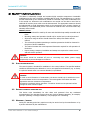
1
Version 1.0
User Manual
Industrial PCs
IPC1300
Industrial PCs IPC1300
Product Portfolio
Copyright
© ads-tec GmbH
Raiffeisenstr.14
D-70771 Leinfelden-Echterdingen
Germany
2
© ads-tec GmbH • Raiffeisenstr.14 • 70771 Leinfelden-Echterdingen
Industrial PCs IPC1300
INDEX
ABOUT US .......................................................................................................................................... 5
1
REMARKS ................................................................................................................................. 6
1.1
RELEVANT DEVICE DOCUMENTATION................................................................................................ 6
1.2
USED SYMBOL EXPLANATION .........................................................................................................6
1.3
DATA, FIGURES AND MODIFICATIONS............................................................................................... 6
1.4
TRADE MARKS ...........................................................................................................................6
1.5
COPYRIGHTS .............................................................................................................................7
1.6
AMBIENT CONDITIONS .................................................................................................................7
1.7
STANDARDS ..............................................................................................................................8
1.8
MODELS .................................................................................................................................. 8
2
SAFETY INFORMATION ................................................................................................................ 9
2.1
PLACE OF INSTALLATION ..............................................................................................................9
2.2
DAMAGE CAUSED BY IMPROPER USE................................................................................................. 9
2.3
WARRANTY / REPAIR ...................................................................................................................9
3
MOUNTING ............................................................................................................................. 10
3.1
MOUNTING OPTIONS ................................................................................................................. 10
3.2
DEVICE MOUNTING ILLUSTRATION IPC1300 (24V DC) ..................................................................... 11
3.3
DEVICE MOUNTING ILLUSTRATION IPC1300 (230V DC) ................................................................... 12
3.4
MOUNTING PROCEDURE ............................................................................................................. 13
4
ADD-ON CARD INSTALLATION..................................................................................................... 14
4.1
PRE-INSTALLATION NOTES .......................................................................................................... 14
4.2
NOTES ON CONFIGURING THE ADD-ON CARD (PNP)........................................................................... 14
4.3
INSTALLING ADD-ON CARDS ........................................................................................................ 15
5
STARTUP ................................................................................................................................ 16
5.1
AVAILABLE INTERFACES.............................................................................................................. 16
5.2
CABLE INSTALLATION ................................................................................................................ 16
5.3
STARTUP PROCEDURE ................................................................................................................ 16
5.4
CHECK OF READINESS FOR OPERATION ........................................................................................... 17
5.5
STATUS INDICATORS ................................................................................................................. 17
6
7
INTERFACES............................................................................................................................ 18
6.1
INTERFACE CONFIGURATION........................................................................................................ 18
6.2
24V DC POWER SUPPLY ............................................................................................................ 18
6.3
230V AC POWER SUPPLY ........................................................................................................... 18
6.4
USB CONNECTIONS .................................................................................................................. 19
6.5
NETWORK CONNECTION (RJ45) .................................................................................................. 20
6.6
SERIAL COM INTERFACE (RS232) ............................................................................................... 20
6.7
EXTERNAL DRIVES .................................................................................................................... 21
6.8
TEMPERATURE MONITORING........................................................................................................ 21
6.9
DVI-INTERFACE ...................................................................................................................... 22
DRIVES .................................................................................................................................. 23
© ads-tec GmbH • Raiffeisenstr.14 • 70771 Leinfelden-Echterdingen
3
Industrial PCs IPC1300
7.1
8
HARD DRIVE / COMPACTFLASH (IDE INTERFACE)............................................................................. 23
SOFTWARE & DRIVER INSTALLATION .......................................................................................... 24
8.1
9
INSTALLING THE OPERATING SYSTEM ............................................................................................ 24
TECHNICAL DETAILS ................................................................................................................ 25
9.1
10
4
COMPUTER TECHNICAL DATA ....................................................................................................... 25
SERVICE AND SUPPORT ............................................................................................................. 26
10.1
ADS-TEC SUPPORT .................................................................................................................... 26
10.2
COMPANY ADDRESS .................................................................................................................. 26
© ads-tec GmbH • Raiffeisenstr.14 • 70771 Leinfelden-Echterdingen
Industrial PCs IPC1300
Pos : 1 /D atentechni k/Allgemei ne Hinweis e/Wir über uns/Wir über uns @ 0\mod_1158743732668_681.doc @ 692 @
ABOUT US
S
ads-tec GmbH
Raiffeisenstr. 14
70771 Leinfelden-Ecchterdingen
Tel: +49 (0) 711 / 45894-0
Fax: +49 (0) 711 / 45894-990
www.ads-tec.com
Germany
ads-tec GmbH provides large enterprises and globally active corporattions with cutting edge
technology, up-to-date know-how and comprehensive services in the area of automation
ocessing technology and systems engineering.
technology, data pro
ements full automation solutions from planning to
o commissioning and is
ads-tec GmbH imple
specialized in handling and material handling technologies.
division develops and produces PC based solutio
ons and offers a broad
The data systems d
range of industrial PCs,
P
thin clients and embedded systems.
ads-tec is specializzed in modifying and optimizing embedded operating systems and
develops software to
ools to complement its hardware platforms.
Pos : 2 /D atentechni k/Allgemei ne Hinweis e/R elevante Dokumentationen zum Gerät/Rel evante D okumentati onen für IPC / PLC /ITC @ 0\mod_1158742442637_681.doc @ 686 @
© ads-tec GmbH • Raiffeisenstr.14 • 70771 Leinfelden-E
Echterdingen
5
Industrial PCs IPC1300
1 REMARKS
1.1
RELEVANT DEVICE DOCUMENTATION
Consult the following documentation for information pertaining to device setup and
operation:
USER MANUAL ON THE SERVICE CD (THIS DOCUMENTATION):
Contains information pertaining to device mounting, startup and operation as well as the
technical data for the device hardware.
SERVICE CD:
Contains drivers, user manual and installation instructions for installing drivers.
Pos : 3 /D atentechni k/Allgemei ne Hinweis e/Erl äuter ung z u den ver wendeten Symbolen/Erläuter ung zu den verwendeten Symbolen @ 0\mod_1158752779484_681.doc @ 690 @
a
1.2
USED SYMBOL EXPLANATION
Warning:
The "Warning" symbol refers to activities which might cause personal injury or damage to
the hardware or software!
Note:
The "Note" symbol familiarises you with conditions to be observed in order to ensure
flawless operation. Additionally, hints and advice are given for a more efficient use of the
device and for software optimisation.
Pos : 4 /D atentechni k/Allgemei ne Hinweis e/D aten, Abbildungen, Änder ung en/D aten,Abbildung en,Änder ungen @ 1\mod_1235480498775_681.doc @ 5163 @
1.3
DATA, FIGURES AND MODIFICATIONS
All texts, data and figures are non-binding. We reserve the right of modification in
accordance with technological progress. At that point in time when the products leave our
premises, they comply with all currently applicable legal requirements and regulations. The
operator/operating company is independently responsible for compliance with and
observance of any subsequently introduced technical innovations and new legal
requirements, as well as for all usual obligations of the operator/operating company.
Pos : 5 /D atentechni k/Allgemei ne Hinweis e/War enzeic hen/Warenz eichen @ 1\mod_1241687656719_681.doc @ 5473 @
1.4
TRADE MARKS
We would like to remind you that all software and hardware designations as well as trade
names of companies used in this documentation are subject to the general, international
trade mark, brand or patent protection laws.
WINDOWS®, WINDOWS® CE and WINDOWS® CE.net™ are trade marks registered by
Microsoft Corp.
Intel® and Pentium® are trade marks registered by Intel Corp.
IBM®, PS/2® and VGA® are trade marks registered by IBM Corp.
CompactFlash® is a registered trademark of the Compact Flash Association.
Pos : 6 /D atentechni k/Allgemei ne Hinweis e/Urheberrecht/Urheberrecht @ 0\mod_1158756954232_681.doc @ 698 @
6
All other nationally and internationally recognised trade marks and product names are
hereby likewise recognised.
© ads-tec GmbH • Raiffeisenstr.14 • 70771 Leinfelden-Echterdingen
Industrial PCs IPC1300
1.5
COPYRIGHTS
This manual, including all contained figures, is protected by copyright law. Any use for
third parties non-compliant with the copyright provisions is prohibited. Any reproduction,
translation as well as electronic and photographic archiving and modification shall only be
permitted after explicit written authorisation by ads-tec GmbH.
Any party in violation of this provision shall be obliged to damage compensation.
Pos : 7 /D atentechni k/Allgemei ne Hinweis e/U mweltbedingungen/U mwelbedingungen für IPC 1100 @ 1\mod_1251187896232_681.doc @ 6146 @
1.6
AMBIENT CONDITIONS
The device can be operated in the following ambient conditions. The device warranty will
be rendered invalid upon noncompliance with these specifications. ads-tec shall not be
held responsible for damages resulting from improper handling.
•
Temperature for devices with HDD
during use
0 … 40°C
in storage
-20 … 60°C
(due to temperature peak value memory inside)
•
Temperature for devices with Compact Flash
during use
-20 … 45°C
in storage
-20 … 60°C
(due to temperature peak value memory inside)
•
•
Humidity
during use
10 … 85% without condensation
in storage
10 … 85% without condensation
Vibration
during use
1 G, 10 … 500 Hz
(DIN EN 60068-2-6)
•
Bump
during use
5 G, at alternation of 30 ms
(DIN EN 60068-2-27)
Pos : 8 /D atentechni k/Allgemei ne Hinweis e/N ormen/N ormen @ 1\mod_1219145812377_681.doc @ 3946 @
© ads-tec GmbH • Raiffeisenstr.14 • 70771 Leinfelden-Echterdingen
7
Industrial PCs IPC1300
1.7
STANDARDS
This unit is compliant with the provisions and safety objectives of the following EU
Directives:
•
This unit is compliant with the CE mark testing specification limits as defined in the
European test standards EN 61000-6-4 und EN 61000-6-2
•
This unit is compliant to the DIN EN 60950 (VDE0805, IEC950) testing
specification limits on “Safety of Information Technology Equipment”
•
This unit is compliant to the DIN EN 60068-2-6 (sinusoidal vibration) testing
specification limits
•
This unit is compliant to the DIN EN 60068-2-27 (shock and bump) testing
specification limits
Note:
A corresponding declaration of conformity is available for competent authorities, care of
the Manufacturer. Said declaration can be viewed at all times upon request.
For full compliance to the legal requirements in force on electromagnetic compatibility, all
components and cables used for unit connection must also be compliant with said
regulations. It is therefore necessary to employ BUS and LAN cables featuring screened
plug connectors, to be strictly installed as per the instructions contained in the User
Manual.
Pos : 9 /D atentechni k/Allgemei ne Hinweis e/Auss tattungs varianten/Auss tattungs varianten für OPC 51xx / IPC 5100/1100 / C PC-Serie / PLC-Serie / OTC-Serie / ITC- Seri e @ 0\mod_1158761169652_681.doc @ 713 @
1.8
MODELS
Two models of the system are provided:
PLATFORM WITH SSD:
This platform has no rotating mass storage media (e.g. hard drives) and incorporates an
embedded operating system (Windows CE.net / XP embedded) for stationary use.
PLATFORM WITH HARD DRIVE:
This model includes a hard drive for stationary use in production environments and
incorporates standard operating systems.
Pos : 10 /D atentec hni k/Betri ebs hi nweis e/Betriebsort/Betri ebs ort für OPC- Seri e / IPC- Serie / C PC- Serie / PLC- Seri e / ITC-Serie / OTC-Serie @ 0\mod_1158827335567_681.doc @ 725 @
8
© ads-tec GmbH • Raiffeisenstr.14 • 70771 Leinfelden-Echterdingen
Industrial PCs IPC1300
2 SAFETY INFORMATION
The device is electrically charged and contains highly sensitive components. Permissible
modification by the user is limited to installing add-on cards. The manufacturer or a service
provider authorized by the manufacturer should be consulted if any other modifications are
to be carried out. Whenever such modifications are carried out the device must first be
switched off and the power cable must be disconnected. The appropriate measures should
be implemented to avoid electrostatic shock to the components upon contact. Opening of
the device by a non-authorized person could result in hazards to the user and renders any
warranty claims invalid.
GENERAL NOTICE:
•
The manual should be read by all users and should be kept readily accessible at all
times.
•
Mounting, startup and operation should only be carried out by trained personnel.
•
All persons using the device should observe the safety information and the
manual.
•
The rules and regulations pertaining to accident prevention should be observed in
the place of device installation.
•
The manual contains the most important information required for safe operation of
the device.
•
Proper storage, transport, installation and startup are required to ensure correct
and safe device operation.
Caution:
The device should be switched off prior to connecting any cables (power supply,
peripherals) to prevent damage to the device.
2.1
PLACE OF INSTALLATION
The control system is intended for installation in the control cabinet. The specified ambient
conditions should always be adhered to. Use in non-specified environments (e.g. on boats,
in explosive hazard areas or at extreme altitudes) is prohibited.
Caution:
In order to avoid formation of condensation, the device should only be switched on once
it has acclimated to the room temperature. The same applies if the device has been
exposed to extreme variations in temperature.
Preventing overheating during operation: The device should not be exposed to direct
sunlight or other sources of light.
Pos : 11 /D atentec hni k/Betri ebs hi nweis e/Sc häden durch uns achg emäß en Gebrauc h/Schäden durc h unsac hgemäß en Gebr auch @ 0\mod_1158827867958_681.doc @ 728 @
2.2
DAMAGE CAUSED BY IMPROPER USE
This device must immediately be shut down and protected from any accidental
commissioning if the operating system shows any obvious damage caused by, for example,
improper operating or storage conditions, or by improper use or handling.
Pos : 12 /D atentec hni k/Betri ebs hi nweis e/Gewährleistung / R eparatur/Gewährleistung / R epar atur @ 0\mod_1158828054427_681.doc @ 730 @
2.3
WARRANTY / REPAIR
During the warranty period any repair must only be carried out by the manufacturer or by
a person authorised by the manufacturer.
Pos : 13 /D atentec hni k/Montage/Montagemöglichkeiten/M ontag emöglichkeit für IPC 1100 @ 0\mod_1158830335724_681.doc @ 742 @
© ads-tec GmbH • Raiffeisenstr.14 • 70771 Leinfelden-Echterdingen
9
Industrial PCs IPC1300
3 MOUNTING
3.1
MOUNTING OPTIONS
The device is intended for installation on control panels. If the device is mounted
somewhere else, then the required ambient conditions should always be provided.
Caution:
Preventing overheating during operation: The device should not be exposed to direct
sunlight or other sources of light.
Measures to prevent heat accumulation should be implemented if the device is installed in
a console, casing or similar enclosing structure. The maximum permissible ambient
temperature should not be exceeded.
The front is only IP65 protected if mounted correctly.
Pos : 14 /D atentec hni k/Montage/Montages kiz zen/Auß enabmess ungen des Ger äts/M ontages kizz e des Ger äts IPC 1100 @ 0\mod_1158840128122_681.doc @ 754 @
Note:
When selecting the mounting housing, the overall performance of the system including
built-in cards has to be observed. The housing has to be calculated correctly, that the
max. permissible ambient temperature is not exceeded.
10
© ads-tec GmbH • Raiffeisenstr.14 • 70771 Leinfelden-Echterdingen
Industrial PCs IPC1300
3.2
DEVICE MOUNTING ILLUSTRATION IPC1300 (24V DC)
© ads-tec GmbH • Raiffeisenstr.14 • 70771 Leinfelden-Echterdingen
11
Industrial PCs IPC1300
3.3
DEVICE MOUNTING ILLUSTRATION IPC1300 (230V DC)
Pos : 15 /D atentec hni k/Montage/Rei henfolge der Montage/Rei henfolge der Montage für IPC 1100 / PLC 300 / ITC-Serie @ 0\mod_1158842002183_6.doc @ 303 @
Pos : 15 /D atentec hni k/Montage/Rei henfolge der Montage/Rei henfolge der Montage für IPC 1100 / PLC 300 / ITC-Serie @ 0\mod_1158842002183_681.doc @ 771 @
12
© ads-tec GmbH • Raiffeisenstr.14 • 70771 Leinfelden-Echterdingen
Industrial PCs IPC1300
3.4
MOUNTING PROCEDURE
•
Use the drilling template to drill holes according the mounting illustration in the
control panel with the specified threading.
•
Insert the upper screws half way into the control panel and hang the device on the
mounting links.
•
Tighten the screws and insert the rest of the screws.
Note:
The device is connected to the power supply using a lead out terminal with a screw
connection. A ground connection does not have to be made, because the grounding
conductor of the device plug or supply connection serves this purpose. If additional
grounding conductors are attached to a grounding screw, a wire diameter of at least 2.5
mm² is specified.
Pos : 16 /D atentec hni k/Stec kkar tenei nbau/Hi nweis vor dem Einbau/Hi nweis vor dem Einbau für IPC 1100 @ 0\mod_1158843763624_681.doc @ 775 @
© ads-tec GmbH • Raiffeisenstr.14 • 70771 Leinfelden-Echterdingen
13
Industrial PCs IPC1300
4 ADD-ON CARD INSTALLATION
4.1
PRE-INSTALLATION NOTES
The user can install CompactFlash or PCI add-on cards such as Interbus cards in the
device. The card slot is accessed by taking off the back cover. The crosshead screws on
the back of the control system should be removed for this purpose.
Caution:
The components in the device are highly sensitive products, which can be destroyed or
impaired by improper handling. The same applies to the PC add-on cards to be installed.
Therefore the appropriate measures have to be implemented in all cases to avoid
electrostatic shock to the components upon contact.
Pos : 17 /D atentec hni k/Stec kkar tenei nbau/Hi nweis zur Konfiguration der Stec kkarten/Hinweis e z ur Konfiguration der Stec kkarte @ 0\mod_1158844984298_681.doc @ 779 @
4.2
NOTES ON CONFIGURING THE ADD-ON CARD (PNP)
The Ethernet and IDE controllers on the adsX board are connected via an internal PCI bus.
Therefore the addresses and IRQs are automatically assigned by the BIOS.
The following should be considered when installing or reconfiguring ISA cards:
•
Install and switch on device without ISA cards and then note down the assigned
IRQs and addresses.
•
Install additional ISA cards in such a way that the IRQs assigned to PCI controllers
are not used again.
•
Reserve IRQs for ISA cards in the BIOS.
Pos : 18 /D atentec hni k/Stec kkar tenei nbau/M ontag e der Z us atz karten/Montage von Z us atz karten @ 0\mod_1158845159907_681.doc @ 781 @
14
© ads-tec GmbH • Raiffeisenstr.14 • 70771 Leinfelden-Echterdingen
Industrial PCs IPC1300
4.3
INSTALLING ADD-ON CARDS
•
Switch off the device and all units connected to the PC and disconnect them from
the power supply.
•
Unscrew the cover screws using a matching screwdriver and carefully remove the
cover.
Caution:
The cover may be connected to mechanical parts in the device by a grounding wire! Do
not remove the cover with force...
•
Reduce electrostatic charge by implementing the appropriate measures (see
above), remove the add-on card from the packaging, place it in the slot and bolt it
to the card mount.
•
Each ISA card should be fastened in the matching slot with a clamp to prevent the
card from falling out.
•
Reconnect the grounding conductor if it has been removed and replace the cover
while paying attention to the side clips as the case may be.
•
Tighten all of the screws on the cover again.
Pos : 19 /D atentec hni k/Inbetri ebnahme/Systemmer kmale/Inbetri ebnahme für IPC 1100 @ 0\mod_1158845850031_681.doc @ 785 @
© ads-tec GmbH • Raiffeisenstr.14 • 70771 Leinfelden-Echterdingen
15
Industrial PCs IPC1300
5 STARTUP
Caution:
The PC should be switched off before disconnecting plugs in order to avoid damage
to electronic components! In order to avoid formation of condensation, the device
should only be switched on once it has acclimated to the room temperature. Pay
attention to the voltage permitted for the device.
You should allow five seconds to pass between switching the device off and switching
it back on.
5.1
AVAILABLE INTERFACES
The devices have the following interfaces as standard.
Note:
Cable shielding of a data cable has to be connected to the plug connection casing (EMC).
The interfaces have to be enabled in the embedded operating system and the matching
drivers have to be installed to be able to use the interfaces.
Pos : 20 /D atentec hni k/Inbetri ebnahme/Kabelmontage/Kabelmontage für OPC- Seri e / IPC 5100 / 5300 / 5500 / 1100 @ 0\mod_1158848147709_681.doc @ 797 @
5.2
CABLE INSTALLATION
The device interfaces and power supply plug are found on the side of the casing. The free
slots and the drives are found in the same place.
Pos : 21 /D atentec hni k/Inbetri ebnahme/R eihenfolg e der Inbetriebnahme/R ei henfolge der Inbetriebnahme für IPC 1100 @ 0\mod_1158850330926_681.doc @ 801 @
5.3
STARTUP PROCEDURE
•
Connect device with suitable power source.
•
Connect the cable for serial / parallel data transfer and fasten the plugs to the
sockets.
•
Connect all further required cables and secure against slippage.
Pos : 22 /D atentec hni k/Inbetri ebnahme/Betriebsberei tschaft prüfen/Betriebsbereitschaft prüfen für OPC/C PC/PLC /OTC /ITC/VMT-Serie(+Monitore) / IPC 5100/5500/2400/1100 @ 0\mod_1158905578361_681.doc @ 806 @
16
© ads-tec GmbH • Raiffeisenstr.14 • 70771 Leinfelden-Echterdingen
Industrial PCs IPC1300
5.4
CHECK OF READINESS FOR OPERATION
Check the device for any hidden damage caused by improper transport, improper
operating or storage conditions or by improper use (e.g. smoke development from the
device, etc.). Immediately shut down the device and prevent any further accidental
commissioning if any damage is detected.
Pos : 23 /D atentec hni k/Schnitts tell en/Exter ne Tastatur/Exter ne Tastatur für OPC / CPC / PLC / OTC / ITC / VMT-Serie / IPC 51/ 53/11/5500 @ 1\mod_1242716042480_681.doc @ 5557 @
Pos : 25 /D atentec hni k/Bedienung/Status-Anzeig en/SYS- LED/SYS- LED für OPC / CPC / PLC / OTC / ITC / VMT (+Monitore) - Seri e / IPC 5100 / 5300 / 5500 / 1100 @ 1\mod_1204714132162_681.doc @ 3406 @
5.5
STATUS INDICATORS
SYS LED (BICOLOURED)
Depending on the colour and type of flashing, different device states are displayed by the
SYS LED.
The following signals are displayed:
•
LED lights green
The device is ready for operation (Power ON).
•
LED is off
The device is switched off. (Power OFF)
Pos : 26 /D atentec hni k/Bedienung/Status-Anzeig en/PLC-LED/PLC- LED für CPC-Serie / PLC-Serie / IPC 1100 @ 0\mod_1158913634323_681.doc @ 835 @
Pos : 27 /D atentec hni k/Schnitts tell en/Sc hnitts tell eneinstellung/Sc hni ttstelleneins tell ung für IPC 1100 @ 0\mod_1158917563619_681.doc @ 851 @
© ads-tec GmbH • Raiffeisenstr.14 • 70771 Leinfelden-Echterdingen
17
Ind
dustrial PCs IPC1300
6 INTERFACES
6.1
6.2
INTERFACE CONFIGUR
RATION
INTERFACE
IRQ
ADDRESS
COM1
4
3F8h
24V DC POWER SUPP
PLY
The supply voltage
e is provided via a lead-through terminal including
g a screw connection.
(The figure shows the socket inside the device)
PIN-NUMMER
SIGNAL NAME
1
24V DC
2
PE
3
0 V DC
wer Supply
Technical Data Pow
•
Power Con
nsumpion:
Max. 150 Watt
•
Input Voltage:
24V DC
Hinweis:
tel „Technische Details“
Die typische Leeistungsaufnahme des Geräts wird im Kapite
aufgeführt.
Pos : 28 /D atentec hni k/Schnitts tell en/Spannungs versorgung/Spannungs versorg ung für IPC 1100 @ 0\mod_1158923315658_681.doc @ 859 @
6.3
230V AC POWER SUP
PPLY
An IEC connector is used as a power
ed cable should be used to connect the device.
supply. The provide
POWER SUPPLY UNIT TECHNICAL DATA
•
Power con
nsumption:
Max. 150 Watts
•
Input volta
age:
100…240V AC
Note:
The device's typic
ical power input is listed in the "Technical Details"" section.
Pos : 29 /D atentec hni k/Schnitts tell en/USB-Ansc hlus s/U SB-Ansc hl uss für OPC / IPC / C PC / PLC / OTC / ITC VMT / MSD- Seri e @ 0\mod_1158923823971_681.doc @ 865 @
18
© ads-tec GmbH • Raiffeisenstr
str.14 • 70771 Leinfelden-Echterdingen
Industrial PCs IPC1300
6.4
USB CONNECTIONS
The USB interfaces are used for connecting peripherals with USB connection. The interface
complies with the USB 2.0 standard.
PIN NUMBER
SIGNAL NAME
1
VDC
2
D-
3
D+
4
GND
Note:
The USB interfaces may be locked using the Lock USB
You'll find this software and the documentation on the service CD.
software
tool.
Pos : 30 /D atentec hni k/Schnitts tell en/Netz werkansc hlus s RJ 45/Netz wer kansc hluss RJ 45 für OPC / IPC / C PC / PLC / OTC / ITC / VMT-Serie/LSI 5015 SEW @ 0\mod_1158924094127_681.doc @ 867 @
© ads-tec GmbH • Raiffeisenstr.14 • 70771 Leinfelden-Echterdingen
19
Industrial PCs IPC1300
6.5
NETWORK CONNECTION (RJ45)
If the drivers required for functioning are installed on the device, the control system may
be integrated in an Ethernet network supporting the 10/100/1000 Mbit standard by using
the Ethernet 10/100/1000BaseT network connector. Specifications of this network topology
must be observed in this case. You can install the drivers required for functioning from the
enclosed service CD, should they not be installed on the device.
PIN NUMBER
SIGNAL NAME
1
TX +
2
TX -
3
RX +
4
NC
5
NC
6
RX -
7
NC
8
NC
Pos : 31 /D atentec hni k/Schnitts tell en/Seriell e Schnitts tell e C OM RS232/Serielle Sc hnitts tell e C OM (RS232) für OPC / IPC / C PC / PLC / OTC / ITC / VMT / M SA- Serie @ 1\mod_1249303286408_681.doc @ 6105 @
6.6
SERIAL COM INTERFACE (RS232)
The serial interface is used for digital and for analogue data transmission as well. The RS
232 interface can be connected by using a commercially available 9-pin SUB-D cable.
PIN NUMBER
SIGNAL NAME
1
DCD
2
RxD
3
TxD
4
DTR
5
GND
6
DSR
7
RTS
8
CTS
9
RI
Note:
This interface is not electrically isolated.
Pos : 32 /D atentec hni k/Laufwer ke/Exter ne Laufwerke/Exter ne Laufwer ke für OPC 5112 / 5115 / 5117 / IPC 1100 / CPC / PLC / OTC / ITC / VMT-Serie @ 0\mod_1158926656205_681.doc @ 880 @
20
© ads-tec GmbH • Raiffeisenstr.14 • 70771 Leinfelden-Echterdingen
Industrial PCs IPC1300
6.7
EXTERNAL DRIVES
By default, no drive for removable media (CD/floppy disk) is integrated in the device.
Additionally the system provides an USB interface, with which an external drive could be
connected. In this case, you'd have to ensure that the equipment used is suitable for use
in an industrial environment.
Warning:
Connecting or disconnecting of external drives during operation is inadmissible, since it
cannot be excluded that the drive is in use at this point in time. Data loss might occur if
not observed!
Pos : 33 /D atentec hni k/Schnitts tell en/Temparaturüber wac hung/T empar atur über wachung für OPC / IPC 5100 / 5300 / 5500 / 1100 / CPC / PLC / / OTC / ITC-Serie @ 0\mod_1158930009922_681.doc @ 887 @
6.8
TEMPERATURE MONITORING
The device includes a function for monitoring the internal temperature. If temperature
inside the device rises above a predetermined level, then an error is indicated via the SYS
LED on the front / interface plate. The alarm can only be reset by switching off the device.
This gives the user time to acknowledge the alarm and introduce appropriate measures.
• Red flashing:
Temperature too high in the device
Pos : 34 /D atentec hni k/Schnitts tell en/DVI-I Ans chl uss /DVI-I Ansc hl uss für IPC 1100 / 5100 / 5300 / 5500 / PLC 500 / MSD 5012 / 5015 @ 0\mod_1158931991936_681.doc @ 892 @
© ads-tec GmbH • Raiffeisenstr.14 • 70771 Leinfelden-Echterdingen
21
Ind
dustrial PCs IPC1300
6.9
DVI-INTERFACE
The DVI-Interface
e is used to transfer analog and digital video signals. A DVI-I Cable is
required to conne
ect a digital display to the device. It is also posssible to connect a VGA
display by using a suitable DVI-VGA adapter.
Note:
The DVI-Interfacce is a Single Link Interface. The DVI-Interface wille
w
be activated only in
operating system
m mode!
PIN-NUMMER
SIGNAL NAME
1
TMDS Data2-
2
TMDS Data2+
3
TMDS Data2/4 Shield
4
N/C
5
N/C
6
DDC Clock [SCL]
7
DDC Data [SDA]
8
Analog vertical sync
9
TMDS Data1-
10
TMDS Data1+
11
TMDS Data1/3 Shield
12
N/C
13
N/C
14
+5V Power
15
Ground (for +5V)
16
Hot Plug Detect
17
TMDS Data0-
18
TMDS Data0+
19
TMDS Data0/5 Shield
20
N/C
21
N/C
22
TMDS Clock Shield
23
TMDS Clock+
24
TMDS Clock-
C1
Analog Red
C2
Analog Green
C3
Analog Blue
C4
Analog Horizontal Sync
C5
Analog GND Return: (analog R,
G, B)
Pos : 35 /D atentec hni k/Laufwer ke/Festpl atte / C ompac t Flash/Fes tpl atte C ompac t Fl ash für OPC-Serie / IPC 5100 / 1100 / C PC-Serie / PLC- Serie / OTC-Serie @ 0\mod_1159168515493_681.doc @ 899 @
22
© ads-tec GmbH • Raiffeisenstr
str.14 • 70771 Leinfelden-Echterdingen
Industrial PCs IPC1300
7 DRIVES
7.1
HARD DRIVE / COMPACTFLASH (IDE INTERFACE)
The choice of storage media depends on individual customer requirements. The following
storage options are available:
Hard drive/SSD: This option implements a 2,5" Festplatte mind. 60 GB (SATA). The hard
drive is formatted using the NTFS file system (Windows XP default).
Note:
Recommendations for choosing the storage medium for a basic installation:
CompactFlash: Windows CE.net / Windows XP Embedded
Hard drive:
Windows XP Professional
Pos : 36 /D atentec hni k/Softwar e / Trei ber Install ati on/Installati on des Betriebss ystems/Installation des Berti ebs s ystems für/IPC 11/C PC/PLC /OTC/ VMT- Seri e/OPC - Seri e @ 1\mod_1247050790255_681.doc @ 5903 @
© ads-tec GmbH • Raiffeisenstr.14 • 70771 Leinfelden-Echterdingen
23
Industrial PCs IPC1300
8 SOFTWARE & DRIVER INSTALLATION
The device will be delivered with a pre-installed Windows operating system on request by
the customer. The drivers required for this are already installed, and the operating system
will be enabled by entering the licence information. Should an initial installation be
required, please adhere to the following steps. With a newer operating system like
Windows XP, the network card and graphics card will properly be recognised during initial
installation, so that only the touchscreen driver and the soft keyboard must be installed
separately.
Note:
If the hard drive was formatted, the operating system can be reinstalled by using one of
the existing interfaces.
An external keyboard is required for installation.
8.1
INSTALLING THE OPERATING SYSTEM
If the device is not equipped with an integrated drive, installing the operating system can
only be carried out by using the USB interface.
Procedure for installation:
USB:
•
The boot drive in the system Bios must be switched to USB in order to boot the
device from the USB interface.
•
Restart the device and insert the Windows CD.
•
Windows installation and basic data setup
•
With devices using a touchscreen, the full functionality range or touchscreen
drivers and the soft keyboard should be installed.
If Windows CE.net or Windows XPe is used, the entire operating system may be
completely installed from the USB stick using the respective image. The required image
can be purchased from the ads-tec company or via the ASSIX online portal.
Pos : 37 /D atentec hni k/T echnisc he Daten/IPC- Serie/T echnisc he Daten für IPC 1100 @ 0\mod_1160393452018_681.doc @ 1179 @
24
© ads-tec GmbH • Raiffeisenstr.14 • 70771 Leinfelden-Echterdingen
Industrial PCs IPC1300
9 TECHNICAL DETAILS
9.1
COMPUTER TECHNICAL DATA
The adsX module standard makes it possible to choose between different performance levels.
IPC1000 series
IPC1300
Computer Data
Processor
Celeron™ 1,2Ghz / Core™ 2 Duo 2,26GHz
RAM
2GB RAM / 4 GB RAM
Chipset
Intel GMA X4500 in GS45 Chipset
Graphic memory
max. 256 MB shared
Mass Storage
2,5“ Automotive Hard Disk min. 60GB (SATA) oder 2,5“ SSD
Interfaces
COM 1 (RS232)
COM 2 (RS232)
1 x DVI-I
6 x USB 2.0
Network
4 x Ethernet (10/100/1000 MBit) RJ45
Slots
2 x PCI, 1 x PCI express
General Data
288 x 118 x 270 mm
External Dimensions
(B x H x T)
ca. 3,8 Kg
Weight
IP20
Protection Class
Power Consumption
ca. 50W
ca. 50W
Max. Switch On Current
24V DC /18A
230V AC /60A
Pos : 38 /D atentec hni k/Ser vic e und Support/Ser vice & Support @ 0\mod_1159176214322_681.doc @ 938 @
© ads-tec GmbH • Raiffeisenstr.14 • 70771 Leinfelden-Echterdingen
25
Industrial PCs IPC1300
10 SERVICE AND SUPPORT
The ads-tec company and their partner companies offer a comprehensive service and
support to your customers providing a quick and professional support in case of any
question with respect to ads-tec products and components.
Since the devices from ads-tech company are also used by partner companies, these
devices might be configured according to customer requirements. Should any question or
issue with respect to specific configurations and software installations arise, it can only be
resolved by the system manufacturer.
For devices not directly purchased from ads-tec, we cannot be responsible for the support.
In this case, the support is provided by our partner company.
10.1 ADS-TEC SUPPORT
The ads-tec support team is available for direct clients from Monday to Friday from
08:30 AM to 05:00 PM using the following phone number:
Phone: +49 (0) 711 / 45894-500
Fax:
+49 (0) 711 / 45894-990
Email: [email protected]
10.2 COMPANY ADDRESS
ads-tec
Automation Daten- und Systemtechnik GmbH
Raiffeisenstraße 14
D-70771 Leinfelden-Echterdingen
Germany
Phone: +49 (0) 711 / 45894-0
Fax:
+49 (0) 711 / 45894-990
Email: [email protected]
Home: www.ads-tec.de
26
© ads-tec GmbH • Raiffeisenstr.14 • 70771 Leinfelden-Echterdingen