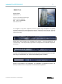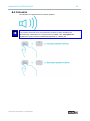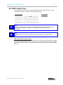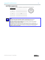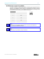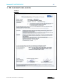
1
Version 2.0 User Manual Industrial PCs OPC6012/6015 Stand:31.10.2014 Industrial PCs OPC6012/6015 2 Product Portfolio Copyright ads-tec GmbH Heinrich-Hertz-Str. 1 D-72622 Nürtingen Germany © ads-tec GmbH • Heinrich-Hertz-Str. 1 • D-72622 Nürtingen Industrial PCs OPC6012/6015 3 INDEX About us ..................................................................................................................................... 5 1 Remarks ..................................................................................................................... 6 1.1 1.2 1.3 1.4 1.5 1.6 1.7 1.8 1.9 Relevant documentation for the device .................................................................................. 6 Explanation of used symbols ................................................................................................... 6 Data, figures and modification ................................................................................................. 7 Trade marks................................................................................................................................ 7 Copyrights .................................................................................................................................. 7 Environmental conditions ......................................................................................................... 8 Standards ................................................................................................................................... 8 Equipment versions .................................................................................................................. 9 Scope of delivery ....................................................................................................................... 9 2 Operating instructions ............................................................................................ 10 2.1 2.2 2.3 2.4 2.5 Operating location ................................................................................................................... 10 Damage due to improper use ................................................................................................. 10 Warranty / repair ...................................................................................................................... 10 Treatment and disposal of lithium batteries ......................................................................... 11 Notes on safety ........................................................................................................................ 12 3 Mounting .................................................................................................................. 13 3.1 3.1 3.2 3.3 External Device Dimensions for OPC6012 ............................................................................ 13 Installation Layout for OPC6012 ............................................................................................ 14 External Device Dimensions for OPC6015 ............................................................................ 15 Installation Layout for OPC6015 ............................................................................................ 16 4 Commissioning ....................................................................................................... 17 4.1 4.2 Available interfaces ................................................................................................................. 17 Check for operational readiness ............................................................................................ 17 5 Operation ................................................................................................................. 18 5.1 5.2 5.3 5.4 Front control keys ................................................................................................................... 18 Soft keyboard ........................................................................................................................... 18 Status indicators ...................................................................................................................... 20 Touch screen............................................................................................................................ 20 © ads-tec GmbH • Heinrich-Hertz-Str. 1 • D-72622 Nürtingen Industrial PCs OPC6012/6015 4 6 Interfaces ................................................................................................................. 21 6.1 6.2 6.1 6.2 6.3 6.4 6.5 Interface setup ......................................................................................................................... 21 24V DC power supply ............................................................................................................. 21 Speakers .................................................................................................................................. 23 USB connections .................................................................................................................... 24 PS/2 connector ........................................................................................................................ 25 Network connection (RJ45) .................................................................................................... 26 Serial COM interface (RS232)................................................................................................. 27 7 Drives ....................................................................................................................... 28 7.1 7.2 Hard drive / Flash SSD ............................................................................................................ 28 External drives ........................................................................................................................ 28 8 Software & driver installation ................................................................................. 29 8.1 8.2 8.3 8.4 8.5 8.6 8.7 8.8 8.9 8.10 Installing the operating system ............................................................................................. 29 Touch screen driver installation ............................................................................................ 30 Configuration Center .............................................................................................................. 31 Automatic brightness adaptation .......................................................................................... 32 USB Lock function .................................................................................................................. 33 ON / OFF pushbutton configuration ...................................................................................... 34 Exemplary RFID application................................................................................................... 35 Soft keyboard .......................................................................................................................... 36 Screen Mob .............................................................................................................................. 36 Soft keyboard installation ...................................................................................................... 37 9 Technical details ..................................................................................................... 38 10 Service and support................................................................................................ 39 10.1 10.2 ads-tec support ....................................................................................................................... 39 Company address ................................................................................................................... 39 11 CE conformity declaration...................................................................................... 40 © ads-tec GmbH • Heinrich-Hertz-Str. 1 • D-72622 Nürtingen Industrial PCs OPC6012/6015 5 Pos : 1 /D atentechni k/Allgemei ne Hinweis e/Wir über uns/Wir über uns @ 2 \mod_1254923190378_6.doc @ 6522 @ ABOUT US ads-tec GmbH Raiffeisenstr. 14 D-70771 Leinfelden-Echterdingen Phone: +49 711 45894-0 Fax: +49 711 45894-990 www.ads-tec.com As a supplier of high tech equipment, ads-tec supports large enterprises and globally operating groups of companies with state-of-the-art technology, know how that is always up to date and delivery of comprehensive services in the area of automation, data and system technology. ads-tec puts entire solutions for automation into practice - from the planning to the commissioning - and has particularly specialised in manipulation and material manipulation technology. The Data Technology division develops and manufactures PC based solutions and holds a wide range of industrial PCs, thin clients and embedded systems available. ads-tec has specialised in the adaptation and optimisation of operational systems and develops software tools to complement the offered hardware platforms. Pos : 2 /D atentechni k/Allgemei ne Hinweis e/R elevante Dokumentationen zum Gerät/Rel evante D okumentati onen für OPC / C PC / OTC / VMT /STC @ 2\mod_1268662117522_6.doc @ 7352 @ © ads-tec GmbH • Heinrich-Hertz-Str. 1 • D-72622 Nürtingen Industrial PCs OPC6012/6015 6 1 REMARKS 1.1 RELEVANT DOCUMENTATION FOR THE DEVICE The following documents are essential for setting up and operating this device: USER MANUAL (THIS DOCUMENTATION): Contains information for installation, commissioning and operating the device along with technical data of the device hardware. WEBSITE By using the website www.ads-tec.de, you can download drivers, software, user manuals, leaflets and flyers from the Download section on the website. Note: We would recommend to make use of our website contents (www.ads-tec.de) in order to ensure an optimised data quality and to be quickly and comprehensively informed of any technical modification. SERVICE CD: Contains drivers and user manuals. Note: The service CD menu automatically starts if the autostart option for removable media is activated. The service CD was created by using Adobe Flash. The service CD menu is even available if the Flash Player is not installed. Pos : 3 /D atentechni k/Allgemei ne Hinweis e/Erl äuter ung z u den ver wendeten Symbolen/Erläuter ung zu den verwendeten Symbolen @ 0\mod_1158752779484_6.doc @ 141 @ 1.2 EXPLANATION OF USED SYMBOLS Warning: The "Warning" symbol refers to activities which could cause personal injury or damage to the hardware and software! Note: The "Note" symbol describes conditions which unconditionally have to be observed in order to ensure trouble-free operation. Additionally, hints and advice for the efficient use of this device and for software optimisation are given using this symbol. Pos : 4 /D atentechni k/Allgemei ne Hinweis e/D aten, Abbildungen, Änder ung en/D aten,Abbildung en,Änder ungen @ 1\mod_1235480498775_6.doc @ 5162 @ © ads-tec GmbH • Heinrich-Hertz-Str. 1 • D-72622 Nürtingen Industrial PCs OPC6012/6015 7 1.3 DATA, FIGURES AND MODIFICATION All texts, data and figures are non-binding. All these materials are subject to modification due to technological progress. Our products comply with all provisions and requirements of the legislation at that point in time when the products leave our company premises. The operator/operating company bears sole responsibility for the compliance with any consecutive new technological development or adherence to any consecutive new legislatory provision, as well as for the observance of their obligation as the operator/operating company. Pos : 5 /D atentechni k/Allgemei ne Hinweis e/War enzeic hen/Warenz eichen @ 2\mod_1263298182965_6.doc @ 6972 @ 1.4 TRADE MARKS We would like to emphasise that all names of hardware and software products used in this documentation, as well as all brand names of corresponding companies are subject to the general copyrights of the intellectual property in terms of trademarks, brand names and patents. ® ® Windows , Windows CE are registered trademarks of Microsoft Corp. ® ® Intel , Pentium , Atom™, Core™2, are registered trademarks of Intel Corp. ® ® ® IBM , PS/2 and VGA are registered trademarks of IBM Corp. ® CompactFlash is a registered trademark of the Compact Flash Association. ® RITTAL is a registered trademark of Rittal Werk Rudolf Loh GmbH & Co. KG. Any other national and international trademarks and product names shall hereby also be recognised. Pos : 6 /D atentechni k/Allgemei ne Hinweis e/Urheberrecht/Urheberrecht @ 0 \mod_1158756954232_6.doc @ 153 @ 1.5 COPYRIGHTS This manual including all contained figures is protected by copyright law. Any use of this manual by a third party in non-compliance with the international copyright law shall hereby be prohibited. Any reproduction, translation and electronic or photographic archiving or modification requires previous written agreement by ads-tec GmbH. In the event of non-compliance, you shall be obliged to compensate for damages. Pos : 7 /D atentechni k/Allgemei ne Hinweis e/U mweltbedingungen/U mweltbedinungen für VMT 60xx- Seri e @ 2\mod_1263307758056_6.doc @ 6981 @ © ads-tec GmbH • Heinrich-Hertz-Str. 1 • D-72622 Nürtingen Industrial PCs OPC6012/6015 8 1.6 ENVIRONMENTAL CONDITIONS The device may be operated under the following conditions. Failure to observe these specifications will terminate any warranty for this device. Ads-tec cannot be held liable for any damages arising due to improper use and handling. Temperature in operation for storage -20 ... 55°C -30 ... 60°C Humidity: In operation For storage 10 … 85% without condensate 10 … 85% without condensate Vibration resistance Standard Additionally applies Shock resistance Standard EN 60068-2-6 / 1 G, 10 … 150 Hz MIL-STD 810F (01.2000), annex C., figure 514.5C (US highway truck transportation) EN 60068-2-27 / 5 G, with a half-wave of 11 ms duration Pos : 8 /D atentechni k/Allgemei ne Hinweis e/N ormen/N ormen für VMT- Seri e @ 2\mod_1263309234182_6.doc @ 6984 @ 1.7 STANDARDS This device complies with the requirements and protective aims of the following EC regulations: This device meets the test requirements for granting the CE sign according to the European test standards EN 61000-6-4 and EN 61000-6-2. This device complies with the test requirements in accordance with DIN EN 60950 (VDE0805, IEC950) "Safety of Information Technology Equipment" The device meets the DIN EN 60068-2-6 test requirements (sinus excitation). The device meets the DIN EN 60068-2-27 test requirements (shock resistance test). Note: All connected components, as well as cable connections must also meet these requirements for compliance with the EMC legislation. For this reason, screened bus and LAN cables including screened connectors must be used and installed according to the instructions in this user manual. Note: By using the CE conformity declaration in this document, you can find detailed information about the standards applicable to this device. © ads-tec GmbH • Heinrich-Hertz-Str. 1 • D-72622 Nürtingen Industrial PCs OPC6012/6015 9 Warning: This is equipment of class A. This unit might cause radio interferences in living areas; in this case the operator might be obliged to take suitable protective measures at the operator’s expense." Pos : 9 /D atentechni k/Allgemei ne Hinweis e/Auss tattungs varianten/Auss tattungs varianten für VMT 6000er Serie @ 2\mod_1263211168928_6.doc @ 6933 @ 1.8 EQUIPMENT VERSIONS The system is available in two equipment versions: Platform including a Flash SSD: Platform without any rotating mass storage medium (hard disc, etc.) and with an embedded operating system (Windows CE 6.0 / XP embedded) for stationary use with a standard Ethernet. Platform including a hard disc: Equipped with a hard disc for stationary use, e.g. in the manufacturing department using a standard operating system. Pos : 10 /D atentec hni k/Allgemeine Hi nweise/Li eferumfang/Li eferumfang für VMT 60xx-Serie @ 2\mod_1263299644184_6.doc @ 6976 @ 1.9 SCOPE OF DELIVERY Please check that all of the following components are contained in the packaging: • 1 x device • 4-pin Lead-through connector from Phoenix Contact • Service CD Optional delivery scope • Operating system Pos : 11 /D atentec hni k/Betri ebs hi nweis e/Betriebsort/Betri ebs ort für VMT-Serie @ 2\mod_1268841352905_6.doc @ 7486 @ © ads-tec GmbH • Heinrich-Hertz-Str. 1 • D-72622 Nürtingen Industrial PCs OPC6012/6015 10 2 OPERATING INSTRUCTIONS This device contains electrical voltages and extremely sensitive components. The manufacturer, or a service partner authorised by the manufacturer, should be consulted if you plan to make any modifications. For this type of work, the device must be switched off at the mains and the power lead must be disconnected. Suitable measures for avoiding electrostatic discharge towards parts of the components when touching the equipment must be taken. If the device is opened by an unauthorised person, hazards for the user might arise and any warranty claim will cease. General instructions: All users must read this manual and have access to it at all times. Installation, commissioning and operation may only be carried out by trained and qualified staff. The security instructions and the manual itself must be observed by all persons who work with this device. At the location of use the valid guidelines and regulations for accident prevention must be observed. The manual contains the most important instructions on how to use this device in a safe way. Appropriate storage, proper transport, installation and commissioning, as well as careful operation are prerequisites for ensuring safe and proper operation of the device. The device can be cleaned by using a soft cloth and a commercially available glass cleaning agent (e.g. Sidolin) with low alcohol content. Warning: Any leads (e.g. power leads, interface cables) may only be connected if the device is switched off in order to avoid damaging the device. 2.1 OPERATING LOCATION The control system is designed for use inside a switching cabinet. You must ensure compliance with the specified environmental conditions. Using the device in non-specified environments, for example on board ships, or in areas that might contain explosive gases, or in extreme heights is prohibited. Warning: The device may only be switched on after acclimatising to the ambient temperature in order to avoid condensate accumulation. The same applies if the device has previously been exposed to extreme temperature variations. To avoid overheating in operation: The device must not be exposed to direct radiation by sunlight or any other light or heat source. Pos : 12 /D atentec hni k/Betri ebs hi nweis e/Sc häden durch uns achg emäß en Gebrauc h/Schäden durc h unsac hgemäß en Gebr auch @ 0\mod_1158827867958_6.doc @ 221 @ 2.2 DAMAGE DUE TO IMPROPER USE If the control system shows any obvious damage, e.g. caused by improper operating or storage conditions or by improper use or handling, you must immediately put the device out of operation and protect it from being accidentally switched on. Pos : 13 /D atentec hni k/Betri ebs hi nweis e/Gewährleistung / R eparatur/Gewährleistung / R epar atur @ 0\mod_1158828054427_6.doc @ 223 @ 2.3 WARRANTY / REPAIR During the warranty period, any repair must be carried out by the manufacturer or by persons duly authorised by the manufacturer only. Pos : 14 /D atentec hni k/Betri ebs hi nweis e/Behandlung und Ents orgung von Lithi um-Batterien/Behandlung und Ents orgung von Lithi um-Batterien @ 1\mod_1247056308470_6.doc @ 5922 @ © ads-tec GmbH • Heinrich-Hertz-Str. 1 • D-72622 Nürtingen Industrial PCs OPC6012/6015 11 2.4 TREATMENT AND DISPOSAL OF LITHIUM BATTERIES This device contains a lithium battery for supplying the system clock with power as long as the supply voltage is not connected. The battery has a life cycle of 3 - 5 years depending on which load is applied. Note: The more the battery is exposed to higher temperatures, the faster it ages. Warning: There is an acute risk of explosion should the wrong type of battery be used. Warning: Do not put lithium batteries into a fire, do not solder on the cell body, do not recharge them, open them, short-circuit them, do not reverse their polarity or heat them up over 100°C; dispose of them properly and protect lithium batteries from direct sun light, humidity and condensation. Lithium batteries may only be replaced by the same type, or by a type recommended by the manufacturer. The lithium battery must be disposed of according to the local legislation at the end of its life cycle. Pos : 15 /D atentec hni k/Betri ebs hi nweis e/Sicherheits hi nweis e/Sicherheits hinweis e @ 0\mod_1162458821197_6.doc @ 1558 @ © ads-tec GmbH • Heinrich-Hertz-Str. 1 • D-72622 Nürtingen Industrial PCs OPC6012/6015 12 2.5 NOTES ON SAFETY Warning: Installation works at the device are only permitted if the device is disconnected from the power supply and protected from accidental switch-on. Note: Always adhere to the safety measures applicable when handling components at risk of being destructed by electrostatic discharges. (EN 61340-5-1 / EN 61340-5-2) Pos : 16 /D atentec hni k/Montage/Montages kiz zen/Auß enabmess ungen des Ger äts/M ontages kizz e / Auß enabmessungen für VMT 6012 @ 1 \mod_1226561943192_6.doc @ 4171 @ © ads-tec GmbH • Heinrich-Hertz-Str. 1 • D-72622 Nürtingen Industrial PCs OPC6012/6015 3 MOUNTING 3.1 EXTERNAL DEVICE DIMENSIONS FOR OPC6012 © ads-tec GmbH • Heinrich-Hertz-Str. 1 • D-72622 Nürtingen 13 Industrial PCs OPC6012/6015 3.1 INSTALLATION LAYOUT FOR OPC6012 Pos : 17 /echni k/Inbetriebnahme/Sys temmer kmal e/Inbetriebnahme für VMT 60xx-Serie @ 2\mod_1263217785475_6.doc @ 6944 @ © ads-tec GmbH • Heinrich-Hertz-Str. 1 • D-72622 Nürtingen 14 Industrial PCs OPC6012/6015 3.2 EXTERNAL DEVICE DIMENSIONS FOR OPC6015 © ads-tec GmbH • Heinrich-Hertz-Str. 1 • D-72622 Nürtingen 15 Industrial PCs OPC6012/6015 3.3 INSTALLATION LAYOUT FOR OPC6015 Pos : 17 /echni k/Inbetriebnahme/Sys temmer kmal e/Inbetriebnahme für VMT 60xx-Serie @ 2\mod_1263217785475_6.doc @ 6944 @ © ads-tec GmbH • Heinrich-Hertz-Str. 1 • D-72622 Nürtingen 16 Industrial PCs OPC6012/6015 17 4 COMMISSIONING The power supply connection and interfaces of this device are installed underneath a protective cover. This cover has to be removed in order to connect the power supply lead and the interface cables. All supply leads and all required data leads have to be connected before commissioning. All supply leads and all required data leads have to be connected before commissioning. Warning: The device must be switched off before connecting or disconnecting any cables in order to prevent damage to the electronics! The device may only be switched on after acclimatising to the ambient temperature in order to avoid condensate accumulation. Make sure to meet the permissible voltage requirements for this device. After switching off and before switching on you must wait for at least 5 seconds. Note: The screen of a data cable must always be connected with the connector housing (EMC). Under the embedded operating system, interfaces must explicitly be enabled and required drivers must be installed in order to be able to use them. 4.1 AVAILABLE INTERFACES Note: If the case is connected with earth potential at the provided PE contact (e.g. by connecting the PE contact with the device plug), the electrical insulation is no longer given. This also applies if the device is installed by using a metal retainer clip. If you want to have the device electrically insulated from the power supply, you have to use a method of installation that ensures appropriate insulation. Pos : 18 /D atentec hni k/Inbetri ebnahme/R eihenfolg e der Inbetriebnahme/R ei henfolge der Inbetriebnahme für VMT 60xx- Seri e @ 1\mod_1222073159179_6.doc @ 4100 @ Pos : 19 /D atentec hni k/Inbetri ebnahme/Betriebsberei tschaft prüfen/Betriebsbereitschaft prüfen für O PC/C PC/PLC /OTC /ITC/VMT-Serie(+Monitore) / IPC 5100/5500/2400/1100 @ 0\mod_1158905578361_6.doc @ 381 @ 4.2 CHECK FOR OPERATIONAL READINESS Check the device for any hidden damage potentially caused by improper transport, operating or storage conditions or by improper use or handling (e.g. smoke development from the device, etc.). If any damage is detected, the device must be put out of service immediately and protected from accidental switch-on. Pos : 20 /D atentec hni k/Bedienung/Fr ontseitig e T asten/Fronts eitige B edi entasten für VMT 60xx-Serie @ 2\mod_1260526652092_6.doc @ 6881 @ © ads-tec GmbH • Heinrich-Hertz-Str. 1 • D-72622 Nürtingen Industrial PCs OPC6012/6015 18 5 OPERATION Pos : 22 /D atentec hni k/Bedienung/T ouch Scr een/T ouch Scr een für VMT 60xx @ 1\mod_1246361069977_6.doc @ 5853 @ 5.1 FRONT CONTROL KEYS Depending on the device equipment version, an operating system (Windows CE.net, Windows XP embedded or Windows XP Prof.) and a soft keyboard are already installed ex factory. The keys on the front panel are occupied with the following functions by a specific driver in the soft keyboard: Level 1: Activate and deactivate the soft keyboard for letter/character input using the touch screen. Level 2: Decrease display brightness Level 1: Change task (Alt+ESC) in Windows. Level 2: Increase display brightness Level 1: Not connected Level 2: The volume can be decreased with devices equipped with an audio output. Level 1: Right mouse-key function Level 2: The volume can be increased with devices equipped with an audio output Shift key (SHIFT) for activating the second keyboard level. This key must be pressed simultaneously with the desired function key Note: If the software keyboard is not installed, only the functions for display settings and volume control are active. The controller display will not be output on the display, in this case. The key functions can be modified in accordance with customer specific requirements. Above described functions are pre-set ex works. Pos : 25 /D atentec hni k/Bedienung/Softkeyboard/Softkeyboar d für OPC / CPC / OTC / VMT / STC- Serie @ 1\mod_1204714082851_6.doc @ 3402 @ 5.2 SOFT KEYBOARD If an operating system is installed ex works, the soft keyboard is also preinstalled. If the operating system is delivered separately with the device, the soft keyboard must also be installed on site. By using the soft keyboard, data can be entered via the touch screen like with an external keyboard. © ads-tec GmbH • Heinrich-Hertz-Str. 1 • D-72622 Nürtingen Industrial PCs OPC6012/6015 19 HOW TO OPERATE THE SOFT KEYBOARD FROM VERSION 3.11: Activate and deactivate the soft keyboard for letter/character input using the touch screen Switches numeric keys on and off (only if numeric keys are visible) Switching between different representations (Alphanumeric keys Numeric keys Function key bar) Soft keyboard representation, zoom in Soft keyboard representation, zoom out Note: If a function is to be activated, which requires pressing two keys at the same time (e.g. Alt + F4), these keys have to be pushed one after another at the soft keyboard, and the special keys Shift, Alt and Ctrl must always be pushed first. Due to differences in programming of a large variety of software, we cannot ensure that the soft keyboard works properly with all software programmes. When deactivating the soft keyboard, the previously active state (alphanumeric / numeric keys or function keys) will be stored and will be displayed when re-activating the keyboard. Pos : 26 /D atentec hni k/Bedienung/Status-Anzeig en/SYS- LED/SYS- LED für OPC / CPC / PLC / OTC / ITC / VMT (+Monitore) - Seri e / IPC 5100 / 5300 / 5500 / 1100 @ 1\mod_1204714132162_6.doc @ 3405 @ © ads-tec GmbH • Heinrich-Hertz-Str. 1 • D-72622 Nürtingen Industrial PCs OPC6012/6015 20 5.3 STATUS INDICATORS SYS LED (BICOLOURED) Depending on the colour and type of flashing, different device states are displayed by the SYS LED. The following signals are displayed: LED lights green The device is ready for operation (Power ON). LED is off The device is switched off. (POWER OFF) 5.4 TOUCH SCREEN The control system is equipped with a touch screen monitor. The touch screen monitor is internally connected with the USB interface. The driver software required for using the touch screen is integrated in the corresponding operating system, or can alternatively be installed from the enclosed service CD. Pos : 23 /D atentec hni k/Bedienung/Status-Anzeig en/SYS- LED/SYS- LED für VMT 60xx- Serie @ 2\mod_1260525540269_6.doc @ 6876 @ os: 25 /D atentechni k/Sc hnittstellen/Sc hnittstellenei nstellung/Schnittstellenei nstellung für VMT- Seri e / PLC 500 @ 0\mod_1158916296612_6.doc @ 517 @ © ads-tec GmbH • Heinrich-Hertz-Str. 1 • D-72622 Nürtingen Industrial PCs OPC6012/6015 21 6 INTERFACES 6.1 INTERFACE SETUP INTERFACE IRQ ADRESS COM1 4 3F8h COM2 (Touch) 3 2F8h Pos : 26 /D atentec hni k/Schnitts tell en/Spannungs versorgung/Spannungs versorg ung für VMT60xx- Seri e @ 2\mod_1260450284020_6.doc @ 6853 @ 6.2 24V DC POWER SUPPLY The supply voltage is provided via a lead-through terminal including a screw connection (Phoenix Contact COMBICON MC 1,5/4-STF3.81). (The figure shows the socket inside the device) PIN-NUMBER SIGNAL NAME 1 PE 2 0V DC 3 NC 4 24V DC Voltage tolerance Input voltage: 24 V DC ± 20%. Current consumption The current consumption of this device depends on the equipment version (e.g. if a heater or WLAN, etc. is installed.) Switch-on current: 7A (1ms) Standby current consumption: 0.25mA Regular operation: 1.3A without heater (without any additional load on the USB ports and without delivering the +5V supply for the scanner) Note: The power supply can be protected with a slow-blow fuse of up to 4A. Note: The typical power consumption of this device is indicated in the "Technical details" chapter. Note: If the case is connected with earth potential at the provided PE contact (e.g. by connecting the PE contact with the device plug), the electrical insulation is no longer given. This also applies if the device is installed by using a metal retainer clip. If you want to have the device electrically insulated from the power supply, you © ads-tec GmbH • Heinrich-Hertz-Str. 1 • D-72622 Nürtingen Industrial PCs OPC6012/6015 22 have to use a method of installation that ensures appropriate insulation. How to proceed if a PE system is used: You must adhere to the following figure in order to ensure a correct installation of the PE system. Pos : 28 /D atentec hni k/Schnitts tell en/Lauts prec her/Lauts prec her für VMT 60xx @ 1\mod_1228482989111_6.doc @ 4247 @ © ads-tec GmbH • Heinrich-Hertz-Str. 1 • D-72622 Nürtingen Industrial PCs OPC6012/6015 6.1 SPEAKERS The OPC60xx is equipped with two internal speakers. Note: The volume can be set up by using the device front keys. When activating the described key combinations, the volume level is modified. If the soft keyboard is installed, the system volume is additionally displayed by a display bar. Pos : 29 /D atentec hni k/Schnitts tell en/USB-Ansc hlus s/U SB-Ansc hl uss für VMT 60xx @ 2\mod_1260457598122_6.doc @ 6860 @ © ads-tec GmbH • Heinrich-Hertz-Str. 1 • D-72622 Nürtingen 23 Industrial PCs OPC6012/6015 24 6.2 USB CONNECTIONS The USB interfaces are used for connecting peripherals with USB connection. These interfaces comply with the USB 2.0 standard requirements. PIN-NUMBER SIGNAL NAME 1 VDC 2 D- 3 D+ 4 GND Note: The device supports a maximum of 8 external USB mass storage devices. If a USB Flash SSD is integrated, a maximum of 7 USB mass storage devices can be connected. Note: The USB interfaces can be individually locked by using the "Lock USB" software tool. USB CONNECTION IN THE FRONT PANEL One USB interface can be accessed from the front. The interface is located under a plastic cover underneath the display. The cover has a tab on the right-hand side, which is used for opening. The plastic cover of the USB interface must be returned in protective position after use. Pos : 30 /D atentec hni k/Schnitts tell en/PS2/Kombi Buc hs e für VMT 60xx @ 2\mod_1268840073235_6.doc @ 7482 @ © ads-tec GmbH • Heinrich-Hertz-Str. 1 • D-72622 Nürtingen Industrial PCs OPC6012/6015 25 6.3 PS/2 CONNECTOR A keyboard can directly be operated by using the PS/2 socket connector. PIN-NUMBER SIGNAL NAME 1 Keyboard Data 2 Maus Data 3 GND 4 +5V 5 Keyboard Clock 6 Maus Clock Note: Since the timing of the integrated controller is specifically set up for cherry keyboards, keyboards of this manufacturer should preferably be used. If the soft keyboard is actively displayed on the monitor, the use of the external keyboard for control purposes is limited. The keyboard must be connected before switching the device on, because the keyboard interface is initialised in the process of booting. If the keyboard is plugged in while the device is running without having had the keyboard connected while booting, it will not be functional. Pos : 31 /D atentec hni k/Schnitts tell en/Netz werkansc hlus s RJ 45/Netz wer kansc hluss RJ 45 für VMT 60xx @ 2 \mod_1260451135970_6.doc @ 6856 @ © ads-tec GmbH • Heinrich-Hertz-Str. 1 • D-72622 Nürtingen Industrial PCs OPC6012/6015 26 6.4 NETWORK CONNECTION (RJ45) If the drivers required for functioning are installed on the device, the control system may be integrated in an Ethernet network supporting the 10/100/1000Mbit standard by using the Ethernet 10/100/1000BaseT network connector. Specifications of this network topology must be observed in this case. You can install the drivers required for functioning from the enclosed service CD, should they not be installed on the device. PIN-NUMBER SIGNAL NAME 1 TX + 2 TX - 3 RX + 4 NC 5 NC 6 RX - 7 NC 8 NC Pos : /Datentec hni k/Sc hnitts tell en/Funknetz wer kkarte/F unknetz wer kkarte für VMT Seri e @ 1 \mod__6.doc @ @ 32600012463645135395856 Note: The device has two separately integrated network controllers of the Realtek RTL 8111c Family PCIe Gigabit Ethernet type. Note: PXE booting is only possible by using the LAN1 port. Pos : 32 /D atentec hni k/Schnitts tell en/Funknetz wer kkar te/Funknetz wer kkarte für VMT 6000 Serie @ 2\mod_1260517076470_6.doc @ 6872 @ Pos : 33 /D atentec hni k/Schnitts tell en/Seriell e Schnitts tell e C OM RS232/Serielle Sc hnitts tell e C OM (RS232) für VMT 60xx @ 1 \mod_1246373571514_6.doc @ 5876 @ © ads-tec GmbH • Heinrich-Hertz-Str. 1 • D-72622 Nürtingen Industrial PCs OPC6012/6015 27 6.5 SERIAL COM INTERFACE (RS232) The serial interface is used for digital data transmission. The RS232 interface can be connected by using a commercially available 9-pin SUB-D cable. Note: Pin 9 of the serial interface connector can be used for additional switching of a 5V power supply, e.g. for operating a serial barcode scanner. The COM +5V switch in the service slot of the device must be put in the ON position in order to use this function. A subsequent restart of the computer might be required in order to properly activate this function. PIN-NUMBER SIGNAL NAME 1 DCD 2 RxD 3 TxD 4 DTR 5 GND 6 DSR 7 RTS 8 CTS 9 RI oder + 5V DC (max. 1 A) Note: This interface is not electrically isolated. Pos : 34 /D atentec hni k/Laufwer ke/Festpl atte / C ompac t Flash/Fes tpl atte C ompac t Fl ash für VMT 60xx-Serie @ 2\mod_1263211316905_6.doc @ 6936 @ © ads-tec GmbH • Heinrich-Hertz-Str. 1 • D-72622 Nürtingen Industrial PCs OPC6012/6015 28 7 DRIVES 7.1 HARD DRIVE / FLASH SSD The storage medium is selected according to the customer requirements. The following options are available for storage: Flash SSD: A Flash SSD with a storage capacity of at least 1GB is used. Its capacity depends on the desired operating system and the additional programmes to be installed. Note: Recommendation for the choice of storage medium with a basic installation: SSD Flash memory: Windows CE 6.0 / Windows XP embedded Hard disk: Windows XP Professional Pos : 35 /D atentec hni k/Laufwer ke/Exter ne Laufwerke/Exter ne Laufwer ke für OPC 5112 / 5115 / 5117 / IPC 1100 / CPC / PLC / OTC / ITC / VMT-Serie @ 0\mod_1158926656205_6.doc @ 563 @ 7.2 EXTERNAL DRIVES By default, no drive for removable media (CD/floppy disk) is integrated in the device. Instead, the system provides a USB interface, to which an external drive can be connected. In this case you'd have to ensure that the used device is suitable for industrial environments. Warning: Connecting or disconnecting external drives during operation is not admissible, since it cannot be excluded that the drive might be in use while connecting or disconnecting it. Data loss might result in the event of non-compliance! Pos : 36 /D atentec hni k/Softwar e / Trei ber Install ati on/Installati on des Betriebss ystems/Installation des Berti ebs s ystems für VMT 60xx @ 2\mod_1263211380903_6.doc @ 6940 @ © ads-tec GmbH • Heinrich-Hertz-Str. 1 • D-72622 Nürtingen Industrial PCs OPC6012/6015 29 8 SOFTWARE & DRIVER INSTALLATION The device will be delivered with a pre-installed Windows / Linux operating system depending on what the customer wants. The drivers required for this are already installed and the operating system will be enabled by entering the licence information. Should an initial installation be required, please follow the following steps. With a newer operating system like Windows XP, the network card and graphics card will properly be recognised during the initial installation, so that only the touch screen driver and the soft keyboard must be installed separately. Note: If the hard drive was formatted, the operating system can be reinstalled by using one of the existing interfaces. An external keyboard is required for installation. 8.1 INSTALLING THE OPERATING SYSTEM The device does not have any integrated CD drive. The installation of the operating system can therefore only be carried out by using the USB interface. Procedure for installation: The boot drive in the system Bios must be switched to USB in order to boot the device from the USB interface. Restart the device and insert a Windows CD. Install Windows and set up the basic data. With devices including touch screens, the touch screen driver as well as the soft keyboard should be installed in order to ensure their full functionality. With Windows CE 6.0 or Windows XP embedded, a complete image can also be installed by using a USB stick. Pos : 37 /D atentec hni k/Softwar e / Trei ber Install ati on/Touc h Screen/Touc h Screen Installation für OPC 5112/5212/5315/5515/5317/5319 / C PC 5006/OTC 5006/ VMT-Serie @ 0\mod_1159175108636_6.doc @ 665 @ © ads-tec GmbH • Heinrich-Hertz-Str. 1 • D-72622 Nürtingen Industrial PCs OPC6012/6015 30 8.2 TOUCH SCREEN DRIVER INSTALLATION Note: When installing the driver, you'll have to take in account that the touch screen monitor is internally connected with the USB interface! Touch screen monitor and PS2 mouse can be operated simultaneously. The installation has to be carried out as described below: Switch on PC and boot. Access the service CD by using the Explorer and start the Installer file in the TouchScreen folder. Follow the on-screen instructions and acknowledge the licence terms and conditions. Once the installer has completed the installation, shut down the computer and restart it subsequently. After restarting, the touch screen monitor has to be calibrated. If the driver does not automatically start, activate the setup menu via "Start => Settings => Control panel => Elo Touchscreen". Via the "Calibration data" menu, calibrating the touch screen monitor can be started, and the crosses appearing in a succession on the monitor have to be pushed for calibration. If the cursor position perfectly matches the touch point of your finger, you can exit this control menu by pushing "OK". Pos : 38 /D atentec hni k/Sondergeräte-M odule/VMT 6000-Serie/VMT 6000-Software Tools @ 2\mod_1268751957235_6.doc @ 7393 @ © ads-tec GmbH • Heinrich-Hertz-Str. 1 • D-72622 Nürtingen Industrial PCs OPC6012/6015 31 8.3 CONFIGURATION CENTER CONFIGURATION The start page of the Configuration Center provides you with an overview of which ads-tec applications are installed on the device. Additionally, you can start any of these applications from the Configuration Center by double-clicking on it. INFORMATION In the Information section, device specific data like the device type, the firmware version and the serial number are listed. The information you'll find here must be indicated whenever you need to contact the support department. © ads-tec GmbH • Heinrich-Hertz-Str. 1 • D-72622 Nürtingen Industrial PCs OPC6012/6015 32 8.4 AUTOMATIC BRIGHTNESS ADAPTATION Note: The application of Automatic brightness adaptation allows the user to configure the respective display brightness. The display brightness can be changed manually, or alternatively automatically by enabling the Automatic brightness adaptation, which controls the brightness automatically depending on the ambient light level. Once the automatic brightness control is enabled, the brightness can no longer be modified by using the front keys. We distinguish between two different control modes with the automatic control: Day mode / Night mode Separate display brightness levels can be programmed for either of both modes. Note: The threshold for Day-/Night mode has to be determined individually by the user for each device. The day mode is enabled as soon as the ambient brightness is high enough. The display brightness should be set to a slightly higher level than at night. The night mode is enabled if the ambient brightness level is low. The display brightness can be set to a lower level in this mode. The operating mode of the automatic control can seamlessly be changed between day and night mode by using a slide control. The closer the slider is to the day mode position, the darker the ambient light must be before the display brightness is changed to night mode. And vice versa: the closer the slider is put to the night mode position, the brighter the ambient light must be before the display brightness is increased to the value set up for the day mode. In order to save the changes, you'll have to push either Save or OK. © ads-tec GmbH • Heinrich-Hertz-Str. 1 • D-72622 Nürtingen Industrial PCs OPC6012/6015 33 8.5 USB LOCK FUNCTION The USB lock function enables you to lock the USB ports, if required, and to avoid access by unauthorised people. MESSAGING In the Messaging section, you can set up whether a message should be output in the event that a USB port is locked or not. Additionally, the locking process can be logged in the event log. PASSWORD PROTECTION In order to avoid any unauthorised access to the USB Lock programme, the settings made can be provided with password protection. In this case, the settings can only be modified if the password was entered correctly. USB INTERFACES The desired USB ports can individually be locked by using the Lock button. All changes must be confirmed with the Save button. © ads-tec GmbH • Heinrich-Hertz-Str. 1 • D-72622 Nürtingen Industrial PCs OPC6012/6015 34 8.6 ON / OFF PUSHBUTTON CONFIGURATION The ON / OFF pushbutton configuration allows to change the behaviour of the ON / OFF pushbutton. REGULAR MODE The ON / OFF pushbutton switched the device on and off. SECURE MODE The ON / OFF pushbutton only switches the device on. The switch-off function is disabled. Note: If the secure mode is used, the device can only be shut down by the software. © ads-tec GmbH • Heinrich-Hertz-Str. 1 • D-72622 Nürtingen Industrial PCs OPC6012/6015 35 8.7 EXEMPLARY RFID APPLICATION The exemplary RFID application was developed in order to test the function of the RFID reader. Note: Function only for devices with RFID possible. Note: In the Interfaces section of the manual you can find more information about the topic of RFIDs. © ads-tec GmbH • Heinrich-Hertz-Str. 1 • D-72622 Nürtingen Industrial PCs OPC6012/6015 36 8.8 SOFT KEYBOARD Here you can configure the soft keyboard application. A large variety of settings, like layout or commands can individually be adapted. All changes must be confirmed by pushing the Save button. 8.9 SCREEN MOB The Screen Mob application was developed in order to disable the touch screen of the device for a certain period of time. This function can be used for cleaning the touch screen. Pos : 39 /D atentec hni k/Softwar e / Trei ber Install ati on/Softkeyboar d/Softkeytastatur für alle Ger ät ohne i nternes Laufwer k(CD/D VD) @ 0\mod_1159175310134_6.doc @ 667 @ © ads-tec GmbH • Heinrich-Hertz-Str. 1 • D-72622 Nürtingen Industrial PCs OPC6012/6015 37 8.10 SOFT KEYBOARD INSTALLATION The soft keyboard must be installed from the enclosed service CD in order to ensure usability of the 5 keys (except for the VMT series, where you have 6 keys) underneath the monitor. The installation has to be carried out as described below: Plug in connector of external drive at the device Switch on PC, insert driver CD into drive after booting Start installer from the service CD Follow on-screen instructions, install the driver, select the language and confirm the restart of the computer. Note: You can make further changes to the basic settings of the soft keyboard, if required. More information about this topic you'll find in the "Readme" file in the installation folder for the soft keyboard! Pos : 40 /D atentec hni k/T echnisc he Daten/VMT-Serie/VMT 60xx-Serie/Tec hnisc he D aten für VMT 6012 @ 1\mod_1228292065027_6.doc @ 4237 @ © ads-tec GmbH • Heinrich-Hertz-Str. 1 • D-72622 Nürtingen Industrial PCs OPC6012/6015 38 9 TECHNICAL DETAILS OPC601x-Series 6012 6015 Display 12,1" TFT 1024 x 768 Pixel 15,1" TFT 1024 x 768 Pixel Represented Colours max. 256K. colours max. 16,1 Mio. colours Display Data Automatic or manual display brightness adjustment Resistive Industrial Touchscreen TouchScreen Computer Data Processor Atom ™ 1,6 GHz RAM 1 GB oder 2 GB DDR2 RAM Chipset Intel® SCH US15W chipset incl. integrated graphic controller Graphic memory max. 8 MB shared Mass storage 2 x Flash SSD (over interal USB-Connection) 1 x Flash SSD (over interal USB-Connection) 2,5" Automotive Harddisk ≥ 40 GB (UDMA) 2,5" SSD PATA ≥ 2 GB Interfaces COM 1 (RS232, connectable 5V power supply for scanner) 1 x PS/2 (Mouse/Keyboard) 2 x USB 2.0 1 x USB 2.0 in Front panel (disconnectable) Network 2 x Ethernet (10/100/1000MBit) RJ 45 General Data External Dimenions 338 x 261 x 62 mm 400 x 305 x 65 mm Weight ca. 3,3 kg ca. 4,3 kg 100W 110W Protection Class Power consumption os: 41 /D atentechni k/Ser vic e und Support/Ser vic e & Support @ 2\mod_1254312498746_6.doc @ 6472 @ © ads-tec GmbH • Heinrich-Hertz-Str. 1 • D-72622 Nürtingen Industrial PCs OPC6012/6015 39 10 SERVICE AND SUPPORT ads-tec and its partner companies offer your customers a comprehensive service and support, which ensures availability of a fast and competent support with respect to all upcoming questions related to ads-tec products or assemblies. Since the devices manufactured by ads-tec are also used by associate companies, these devices might be configured in customer specific ways. Should any questions arise with respect to these specific configurations and software installations, they can only be answered by the system manufacturer. For devices not directly purchased from ads-tec we don't deliver any support. The support is delivered by our associate companies in these cases. 10.1 ADS-TEC SUPPORT The ads-tec support team is available for direct clients from Monday to Friday from 08:30 AM to 05:00 PM using the following phone number: Phone: +49 (0) 7022 2522-202 Fax: +49 (0) 7022 2522-2602 Email: [email protected] 10.2 COMPANY ADDRESS ads-tec GmbH Heinrich-Hertz-Str. 1 D-72622 Nürtingen Germany Phone: Fax: E-Mail: Home: +49 (0) 7022 2522-0 +49 (0) 7022 2522-400 [email protected] www.ads-tec.de Pos : 42 /D atentec hni k/Sondergeräte-M odule/VMT 6000-Serie/C E-Konformitätser kl ärung @ 2\mod_1268396604587_6.doc @ 7322 @ © ads-tec GmbH • Heinrich-Hertz-Str. 1 • D-72622 Nürtingen Industrial PCs OPC6012/6015 11 CE CONFORMITY DECLARATION Gloss ar y OPC6012 Glsar y © ads-tec GmbH • Heinrich-Hertz-Str. 1 • D-72622 Nürtingen 40 Industrial PCs OPC6012/6015 OPC6015 ===== End of bill of materi als ===== © ads-tec GmbH • Heinrich-Hertz-Str. 1 • D-72622 Nürtingen 41