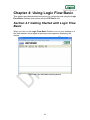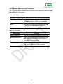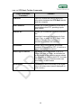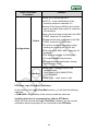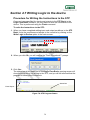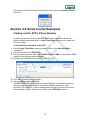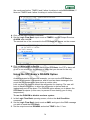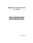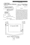
1
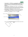
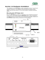
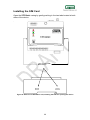
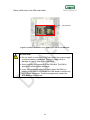
STP Basic 'Smart Terminal Plus' Basic Stand Alone GSM/GPRS Multi-Purpose Controller supports MODBUS RTU with Logic Flow Basic Configuration Software User Manual Revision Preliminary 1 Notes The reader is advised to read this manual carefully and to understand its contents before using any devices. Warranty claims for damage arising from failure to observe the instructions given in this manual are invalid. We accept no liability for consequential damage arising from the failure to observe the contents of this manual. Duetech Beres reserves the right to make technical modifications or alterations to this manual at any time without prior notice. Various registered trademarks, company names and brand names appear in this manual. Even if not designated as such, the relevant proprietary rights still apply. ©2009 Duetech Beres, Ltd. All rights reserved. The copyright and proprietary rights in the guide belong to Duetech Beres, Ltd. It is strictly forbidden to copy, duplicate, sell, lend or otherwise use this guide in any way, shape or form without the prior consent of Duetech Beres, Ltd. This product is based on software developed by Duetech Beres, Ltd. Redistribution of this manual and its use in binary form (PDF) are permitted, provided that the above copyright notice and this paragraph are duplicated in all such forms and that any documentation, advertising materials and other materials related to such distribution and use, acknowledge that the software was developed by Duetech Beres, Ltd. THE SOFTWARE IS PROVIDED “AS IS” AND WITHOUT ANY EXPRESS OR IMPLIED WARRANTIES, INCLUDING, WITHOUT LIMITATION, THE IMPLIED WARRANTIES OF MERCHANTABILITY AND FITNESS FOR A PARTICULAR PURPOSE. 2 TABLE OF CONTENTS TABLE OF CONTENTS ..................................................................................3 CHAPTER 1: INTRODUCTION .......................................................................6 SECTION 1.1 ABOUT THIS MANUAL ...................................................................6 SECTION 1.2 USES OF THE STP BASIC .............................................................6 SECTION 1.3 SAFETY ADVICE...........................................................................7 SECTION 1.4 STP BASIC FEATURES AND BENEFITS ...........................................8 CHAPTER 2 OVERVIEW ................................................................................9 SECTION 2.1 STP BASIC GENERAL DESCRIPTION ..............................................9 STP Basic Dimensions ...............................................................................9 Input Events..............................................................................................11 Output Events...........................................................................................13 Hardware Description ...............................................................................15 CHAPTER 3 INSTALLING THE STP BASIC ................................................17 SECTION 3.1 PACKAGE CONTENTS .................................................................17 SECTION 3.2 HARDWARE INSTALLATION ..........................................................18 Mounting the STP Basic Unit....................................................................18 Connecting the GSM Antenna ..................................................................19 Installing the SIM Card .............................................................................20 Connecting the RS232 cable ....................................................................22 Attaching the Relay Output.......................................................................22 Installing the Voltage Output ....................................................................24 Installing the Digital Input .........................................................................25 Connecting the Power Supply ..................................................................26 Establishing RS485 Communication ........................................................28 SECTION 3.3 STP OPERATION .......................................................................30 Status LEDS .............................................................................................30 Reset Button.............................................................................................32 3 CHAPTER 4: USING LOGIC FLOW BASIC .................................................33 SECTION 4.1 GETTING STARTED WITH LOGIC FLOW BASIC ...............................33 STP Basic Menus and Toolbar .................................................................34 SECTION 4.2 CONFIGURATION SETTINGS ........................................................38 Configuration Settings Screen ..................................................................38 SECTION 4.3 READ INPUTS COMMAND ............................................................41 PHONEBOOK SETUP ......................................................................................41 Adding a Number to the Phonebook.........................................................41 Removing a Phone Number from the Phonebook ....................................43 Exporting a List of Phone Numbers from the Phonebook into a File ........43 Importing a List of Phone Numbers into the Phonebook ..........................43 SECTION 4.4 SETTING THE STP'S INPUT EVENT ..............................................44 "Digital" Input Event..................................................................................46 "OUTPUT" Input Event .............................................................................46 "Main Power" Input Event .........................................................................47 "Vout" Input Event ....................................................................................47 "Timer" Input Event...................................................................................48 "SMS" Input Event ....................................................................................49 "RS232" Input Event.................................................................................51 "DISARM" Input Event ..............................................................................52 "STARTUP" Input Event ...........................................................................52 "Tag Change" Input Event ........................................................................53 SECTION 4.5 SETTING THE STP'S OUTPUT EVENTS .........................................54 "Digital" Output Event ...............................................................................55 "Vout" Output Event..................................................................................56 "Timer" Output Event ................................................................................56 "SMS" Output Event .................................................................................57 "GPRS" Output Event ...............................................................................58 "RS232" Output Event ..............................................................................59 "Outgoing Call" Output Event ...................................................................59 "Buzzer" Output Event ..............................................................................60 "Reset" Output Event................................................................................60 "DISARM" Output Event ...........................................................................61 "ALARM" Output Event.............................................................................61 4 "MODBUS READ " Output Event .............................................................62 "MODBUS WRITE " Output Event............................................................64 SECTION 4.6 EDITING THE STP BASIC INSTRUCTION SET .................................68 Saving a set of instructions in a file ..........................................................68 Loading a saved set of instructions ..........................................................69 Removing instructions from the list...........................................................70 Editing the Instruction List ........................................................................71 Expanding/Collapsing the Instruction List .................................................72 SECTION 4.7 WRITING LOGIC TO THE DEVICE ..................................................73 Procedure for Writing the Instructions to the STP.....................................73 SECTION 4.8 SOME USEFUL EXAMPLES ..........................................................74 Finding out the STP’s Phone Number ......................................................74 Using the STP Basic’s DISARM Option to Set an Alarm ..........................75 Using the STP Basic Timer Option ...........................................................75 Using the STP Basic’s DISARM Option....................................................76 CHAPTER 5: FOR FURTHER INFORMATION.............................................78 5 Chapter 1: Introduction The STP (Smart Terminal Plus) Basic is a user-friendly, general-purpose GSM/GPRS cellular programmable controller. The STP Basic acts as a MASTER device and supports multiple expansions using half-duplex MODBUS RTU protocol (RS485). The STP Basic can be used for a wide variety of purposes: Agriculture Home automation Security. The STP Basic accepts three digital inputs, three dry-contact (relay) outputs and has one voltage output. Section 1.1 About This Manual This manual will guide you through the setup and major uses of the Smart Terminal Plus Basic (STP Basic), a powerful remote control and monitoring device. This manual includes: A list of the uses of the STP Basic STP Basic features and benefits A general description of the STP Basic Instructions for installing the STP Basic hardware Instructions for installing the Logic Flow Basic software Instructions and examples of using the Logic Flow Basic interface Section 1.2 Uses of the STP Basic The STP Basic owes its name to the fact that it employs a minimal number of inputs and outputs and the ability to communicate with up to 32 devices using MODBUS RTU communication. However, this poses no limitation on the range of uses for the STP Basic. You can employ the STP Basic in: Security Home and Industrial automation Gate Control General Warning System Gateway Telemetry solutions Agriculture Climate Monitoring Cooling Control Automation 6 Section 1.3 Safety Advice The STP Basic designed to be used only under the prescribed conditions. Ensure that all the specifications stated in this manual are observed. Tampering with the hardware or software, or failure to observe the warnings stated in this manual may lead to serious physical injury or damage to the device. We assume no liability in such cases, and any warranty claims will become void. The safety regulations specified for the device must be observed during the installation, maintenance and use of the device. This manual contains special instructions that are important for the safe and proper handling of the device. The warning symbols you will encounter in the manual have the following meaning: DANGER: Indicates warning of possible danger to the life and health of the user if the relevant safety measures are not taken. ATTENTION: Indicates warning of possible damage to the device, software, or other material damage if relevant safety measures are not taken. 7 Section 1.4 STP Basic Features and Benefits Some unique features of the STP Basic are: Quad-Band GSM/GPRS allowing you to access and control the STP Basic device via your cellular phone or the Internet An RS232 interface for direct communication with the STP Basic controller, as well as for user-defined purposes (PLC, PC, GPS to any RS232 device) An RS485 half-duplex interface for communicating with up to 32 slave devices with a direct drop down connection. An event report, which allows to make the STP Basic send a report to user via Serial Communication. (RS232). This way, the user can create Word/Excel reports based on the data from the STP. Internal Li-Ion rechargeable backup battery, for sending a power failure alarm (via SMS or GPRS) in case the main power supply is cut off. Accompanying the STP Basic is the Logic Flow Basic Configuration software package. Some features of the Logic Flow Basic program are: Allows you to program the STP Basic device to control a system and do the desired controller tasks quickly and efficiently Allows you to monitor your system. 8 Chapter 2 Overview This chapter provides a brief Overview of the STP Basic and includes the following: General Description Hardware Description Section 2.1 STP Basic General Description The STP Basic is a stand-alone, multipurpose terminal with extended logic control, with cellular capabilities. The STP Basic has a RS485 interface and can communicate using the protocol MODBUS RTU with up to 32 slave devices in a direct drop down connection. The STP Basic accepts three digital inputs, three dry-contact (relay) outputs and one voltage output. STP Basic Dimensions Figure 1: Front View of the STP Basic 9 Figure 2: Side View of the STP Basic Showing Dimensions 10 Input Events The STP Basic supports 17 different types of input events, seven external, and ten internal: Table 1: STP Basic external Inputs External Input Description Three DIGITAL INPUTS: These can include: Thermostat Smoke detector Motion sensor SMS: An SMS message from your mobile phone. INCOMING CALL: Allows the STP Basic to respond to an incoming call (the STP will reject the incoming call and only use the Caller ID, if needed). RS232: An RS232 message from any capable device (for example, a computer or a PLC). RS485: An RS485 half-duplex terminal block and RJ45 communication terminal that support up to 32 slave devices in a direct dropdown connection. Compatible with MODBUS RTU devices, for example: computer or PLC 11 In addition, there are ten other input events that the STP Basic essentially can send to itself. These are shown in the following table: Table 2: STP Basic internal Inputs Internal Input Description TIMER1-4: Triggers as timer event occurs. OUTPUT 1-3: To have the STP Basic respond to an output change caused by a particular event. DISARM: triggers when disarm status has changed. STARTUP: Performs the specified output event when the device is started, or if the user presses the Reset button. Vout: triggers the device when the status has changed. 12 Output Events The STP Basic allows for 17 different types of output events and messages. 10 of the outputs are to external devices, while 7 are internal messages that the STP Basic employs itself. The 10 outputs to external devices are illustrated in the following table: Table 3: Outputs from STP Basic to external device Output to External Device Description Three DIGITAL OUTPUTS (relayed): Dry contact output that can be used for general control tasks. One controlled voltage output which connected to the source voltage of the STP Basic SMS: An SMS message to your mobile phone GPRS: A GPRS message to your TCP/IP Internet server OUTGOING CALL: Outgoing call to a predefined phone number. The STP Basic will make the call and hang up after one ring. DISARM: disables/enables all output events. RS232: An RS232 message to any capable device (for example, a computer PLC) RS485: An RS485 half-duplex terminal block and RJ45 communication terminal that support up to 32 slave devices in a direct dropdown connection. Compatible with MODBUS RTU devices, for example: computer or PLC 13 The other 7 outputs are shown in the following table: Table 4: Outputs from STP Basic to itself Output Description TIMER1-4: used to set up a defined amount of time before timer is triggered RESET: Resets the device upon receiving the specified input. BUZZER: Makes the STP Basic unit emit a buzz. ALARM: Makes the STP Basic unit emit a high pitched alarm sound. 14 Hardware Description The STP Basic is a simple and easy to use controller, which can be operated without any code knowledge necessary. Here is a brief summary of the hardware the STP Basic employs: Figure 3: STP Basic Input and Output Packaging: The STP Basic is packaged in a small (101 x 94 x 37.5 mm) polystyrene case. The casing allows for a DIN rail mount, to insure ultimate safety and stability of the device. Input and Output: The STP Basic allows for three digital inputs (between 0-24V DC), three dry-contact outputs (a relay) and one controlled voltage output that equals to main source voltage. Durability: The STP Basic operating temperature is between -30°C to 85°C, allowing it to withstand the harshest conditions. GSM/GPRS technology: The STP Basic device is based on GSM/GPRS network therefore a SIM card (not included in the STP Basic kit) must be inserted before applying power. RS485 (MODBUS RTU Half Duplex): The STP Basic support up to 32 slave devices and expansions connected directly in a dropdown connection. 15 Programmable: The STP Basic is a programmable controller: you program its logic by means of the Logic Flow Basic software, and write the commands to the device. An RS232 cable communicates with the STP Basic to write the commands from the serial port on your computer to the STP Basic. Indication LEDs: The STP Basic has three LEDs: a red LED indicating power supply to the device and device's processing, a green LED indicating whether the device is registered with the cellular network and orange LED that indicates the user about various conditions for his choice. Backup Battery: The STP Basic also features an internal rechargeable Li-ion backup battery, which allows it to send a power failure alarm, either via SMS or GPRS, in the event that the 9-24 V DC main power fails. Reset button: The STP Basic also features a reset button. Indicator LEDs Reset Button Figure 4: Front view of STP Basic, showing placement of indication LEDs and Reset Button 16 Chapter 3 Installing the STP Basic Installing the STP Basic is a simple procedure that should take no more than a few minutes. This chapter contains instructions for installing both hardware and software. Section 3.1Package Contents The STP Basic unit comes in a kit with the accessories listed in the table below. The table lists the contents of the kit and their part numbers. Table 5: Package Contents Part Description QTY STP Basic Controller Unit 1 Power Supply 12 V DC Voltage Transformer 1 PS220121 DIN Rail 1 STP00701 GSM Antenna 1 AP001A00 GSM Antenna 90 deg 1 RUB009A CD of Documentation and Logic Flow Basic installation software 1 CDR0001 17 P/N Section 3.2 Hardware Installation The installation of the STP Basic can be completed in minutes. You will need a pocket screwdriver (not supplied in the kit) to attach the power supply, digital input and relay output a 3.5-mm wide Phillips or flathead screwdriver will do. Mounting the STP Basic Unit Mount the STP Basic by pushing or snap fitting it onto a DIN rail (top-hat rail 35 mm). Pull out the black tab on the STP Basic device using a screwdriver, and snap the device onto the DIN rail. Ensure that the retaining mechanism of the STP Basic snaps cleanly and securely onto the DIN rail. 35 mm DIN rail Figure 5: Top view of STP Basic attached to DIN rail Figure 6: Side view of STP Basic Black Tab 18 ATTENTION: Do not force the STP Basic onto the DIN rail. Forcing the device on the rail may crack the black tab or the STP Basic casing, and may seriously compromise the stability of the device. DANGER: The device must only be used in rooms that are dry and clean. Protect the device from humidity, water or heat. The device must not be used in environments containing flammable gases, fumes or dust. Do not subject the device to shock or severe vibrations. Connecting the GSM Antenna Screw the GSM antenna (included with the STP Basic device) onto the STP Basic antenna SMA connector. The antenna serves the same purpose as the antenna of any cellular phone. The antenna must be attached for optimal performance of the device. Figure 7: Side View of STP Basic Showing Antenna Connector SMA Connector for the GSM Antenna POWER INPUT 9-24 VDC ATTENTION: Detaching the antenna while the STP Basic is powered on may damage the device. 19 Installing the SIM Card Open the STP Basic casing by gently pushing in the two tabs located at both sides of the device. . Tabs on side of STP Basic Device Figure 8: Side view of STP Basic unit, showing the tabs for opening the device 20 Place a SIM card in the SIM card holder. SIM Card Slot Figure 9: Inside of STP Basic unit, showing the slot for the SIM card ATTENTION: Do not insert or remove the SIM card when the power supply or backup battery is attached. Doing so might result in damage or loss of data on the SIM card! Avoid touching the contacts of the SIM card. The SIM is sensitive to electrostatic discharge. If you are installing a used SIM card, insert the SIM in a mobile phone first to ensure that the SIM doesn't contain any saved SMS messages. These messages may cause the STP Basic to malfunction. 21 Connecting the RS232 cable Connect the RS232 cable (supplied with the STP Basic) to the STP Basic unit via the socket labeled "RS232". Figure 10: View of STP Basic, showing the RS232 socket If RS232 connector is not located on your computer, than a converter of USB to RS232 (not supplied in kit) will be needed instead. Attaching the Relay Output The STP Basic has three relay (dry-contact) outputs. These outputs are configured by default (using jumper) to be at normally open (NO) status. To change the default connection to normally closed, the user can replace the jumper located on the PCB to the appropriate location. ATTENTION: When attaching the inputs and outputs, be sure to use wire within the range of 24-16 AWG (0.25 – 1.5 mm2 gauge). Figure11: Input-Output side of STP Basic, illustrating where to attach the relay output The terminal blocks used by the relay outputs are enumerated in the following table: 22 Table 6: Ports for Attaching the Relay Outputs Digital Output 1 Digital Output 2 Digital Output 3 Terminal Block Number Purpose Terminal 3 C- Common 3 Terminal 4 NO/C3 – Normally Open/Close Connects the circuit when the relay is activated Disconnects the circuit when the relay is inactive Option of Normally Open or Close is decided by jumper Terminal 5 C2- Common 2 Terminal 6 NO/C2 – Normally Open/Close Connects the circuit when the relay is activated Disconnects the circuit when the relay is inactive Option of Normally Open or Close is decided by jumper Terminal 7 C1- Common 1 Terminal 8 NO/C1 – Normally Open/Close Connects the circuit when the relay is activated Disconnects the circuit when the relay is inactive Option of Normally Open or Close is decided by jumper The STP Basic device can be used to control three digital outputs. In the following illustration, one load is attached to the STP to the Normally Open terminal, Upon receiving the specified input, the load attached to NO/Cx will be part of a complete circuit, 23 Figure 12: Simple circuit illustrating the STP Basic Attached to an output load Installing the Voltage Output The STP Basic has one controlled Voltage Output. The value of this can be changed according to the main input voltage of the STP Basic. Practically, the source input voltage can range from 9-24 VDC, and therefore the output voltage can range from 9-24 VDC. For example: If main input voltage is 20 VDC, the Vout will be 20VDC. If main input is 12 VDC, the Vout will be 12 VDC. Figure 13: Input-Output side of STP Basic, illustrating where to attach the voltage output The following table illustrates the placement of the Digital Inputs leads: Table 7: Terminal Blocks for Attaching the Digital Input Terminal Block Number Purpose Terminal 1 (-) Minus sign- GND Terminal 2 (+) Plus sign - Voltage Output 24 Installing the Digital Input The STP Basic accepts three digital inputs that must be within the range 0-24VDC. ATTENTION: Be certain not to exceed the maximum input voltage of 24 V DC. Exceeding this value may cause irreparable damage to the STP Basic unit! Figure 14: Input-Output side of STP Basic, illustrating where to attach the digital input The following table illustrates the placement of the Digital Inputs leads: Table 8: Terminal Blocks for Attaching the Digital Input Terminal Block Number Purpose Terminal 9 (-) Minus sign - GND Terminal 10 3+ –Digital Input 3 Terminal 11 2+ –Digital Input 2 Terminal 12 1+ –Digital Input 1 25 Connecting the Power Supply Once you have completed all the other installation steps, you can attach the power supply to the STP Basic unit. The STP Basic operates on the range between 9-24 VDC. The STP Basic kit contains a transformer that converts the wall voltage to 12 VDC. The connector has two bare wires, one to be connected to the negative terminal, and one to the positive terminal of the STP Basic unit. The striped wire is connected to the negative (or "ground") terminal, and the solid black wire from the transformer is connected to the positive terminal. The STP Basic unit has numbered rows of terminal blocks. Insert the leads into the appropriate terminal blocks on the side of the STP Basic unit, using a 3.5-mm wide flathead or Phillips screwdriver. Figure 15: Attaching the power VCC GND 26 The following table shows the correct connections of the transformer to the STP Basic. Table 9: Terminal Blocks for Attaching the Power Supply to the STP Basic Terminal Block Number Purpose Terminal 13 GND lead from transformer Terminal 14 Positive power supply lead from transformer ATTENTION: Ensure the correct polarity of the power supply terminals. If using another DC voltage source, be certain not to exceed 24 V. This will cause irreversible damage to the STP Basic unit. DANGER: The device should be wired in a de-energized state. Regularly check the live cables to which the devices are connected for faults or breaks in the insulation. If any such fault is found, immediately turn off the device and replace the wiring. 27 Establishing RS485 Communication The STP Basic supports RS485 half-duplex communication using the MODBUS RTU protocol. Using this method, it would be possible to connect up to 32 SLAVE MODBUS RTU devices in a single drop down connection. The following figures show two options for connection of the RS485 and a method on how to connect more then one SLAVE device with a drop down connection. First method is using the block terminals located at the top side of the STP Basic box. This kind of method is especially to slave devices that have a block terminal as a communication port. With this connection, two simple conductive wires are needed. Just keep in mind to connect the positive (none inverting) and the negative (inverting) ports with the same kind in the slave device. Figure 16: Attaching RS485 Communication using block terminal Figure 17: Multiple SLAVE devices in drop down connection using 2-wire block terminal 28 Table 10: Terminal Blocks for Attaching the RS485 communication Terminal Block Number Purpose Terminal 15 B/D- Terminal 16 A/D+ non inverted signal inverted signal Second method is using a cable with RJ45 connector (supplied with kit) located at the top side of the STP Basic box. This kind of method is used only when the slave device supports MODBUS communication through this port. Figure 18: Attaching RS485 Communication using COM2 connector Figure 19: Multiple SLAVE devices in drop down connection using 2-wire block terminal for more detailed information and example on how to connect the STP Basic to a SLAVE device please refer to: "MODBUS connection with DELTA slave" application note, using this link: http://www.duetech.gberes.com/duetech_web/index.php?option=com_content&view=article&id=26&Itemid=19 29 Section 3.3 STP Operation Status LEDS The STP Basic has three status LEDs to indicate that you have installed everything properly and that the device is in proper working order. The red LED indicates that the device is receiving power. The green LED indicates that the device is registered to the cellular network. Red PWR LED Green Register LED Orange Indication LED Figure 20: Status LEDs in STP Basic Red PWR LED After applying the 12 VDC power supply, or inserting the back-up battery, check that the red PWR LED lights up. The red PWR LED indicates that the main power is applied, or that the backup battery is properly attached. Table 11: PWR LED Indications LED Indication Operation Status No indication No power Red, blinking When STP unit is sending a SMS or GPRS message Red, steady Power on As we will see later on in the section dealing with the Logic Flow Basic software, the red light will flash when the STP Basic sends an SMS or GPRS message. 30 Green GSM LED The green GSM LED indicates that the unit registers to the network. When you first power up the STP Basic, or press Restart, the device emits 4 beeps, and in a few seconds the green LED lights up. The green LED will remain lit continuously for five seconds, while the device is searching for the cellular network. A lower-pitched beep then indicates that the device is connected and functioning, and the green LED subsequently flashes periodically. During normal functioning of the device, the green LED serves as the modem registration indicator. This light is on when the modem powers up, and flashes when the STP Basic is registered with the cellular network. Table 12:Green REG LED Indications LED Indication Operation Status No indication GSM unit Off Green, steady Device is searching for the network connection Green, blinking Connected to a network Orange IND LED The orange IND LED is acting as a user indication signal. The user can configure using the STP Basic Logic Flow the operation status of the LED, such as: Duration blinking time. LED will lit up led will lid up due to an input/output event. NOTE: More useful examples and features will be explained in due course. 31 Reset Button If you encounter a problem with the functioning of the device, use the Reset button on the front of the device to reset the STP. This will allow you to restart the device without having to detach it from the power supply. Reset Button Figure 21: STP Basic Reset Button 32 Chapter 4: Using Logic Flow Basic This chapter provides detailed instructions for configuring and using the Logic Flow Basic Software that comes with the STP Basic unit. Section 4.1 Getting Started with Logic Flow Basic When you click on the Logic Flow Basic Platform icon on your desktop or in the Start taskbar, the program's opening screen appears, displaying the menus. Figure 22: Logic Flow Basic Opening Screen 33 STP Basic Menus and Toolbar The following table enumerates the functions on the opening screen of Logic Flow Basic and their uses: Table 13:File Menu Menu Item Function Load File Allows you to load a set of conditions to the STP Basic device, saved in a *.cond file Save Allows you to save the conditions you have supplied to the STP Basic device in a *.cond file Table 14: Logic menu Menu Item Function Write To Device Writes the list of instructions to the device Read From Device Reads the present list of instructions from the device and displays it on the screen (included in future release) Erase Device Erases the logic that has been written to the device (included in future release) 34 Table 15: STP Basic Toolbar Commands Logic Flow Basic Command Function COM Port Opens or closes the RS232 serial port connection between the STP Basic device and the computer Add Condition Allows you to add a condition to the list of commands to the STP, providing inputs and outputs Remove All Allows you to erase all conditions from the list. Note that it removes conditions only from Logic Flow, to erase the STP Basic, click 'Write to Device' after removing all conditions to update the hardware. Phonebook Allows you to store names and phone numbers of users of the STP, to receive or send messages to the device Write Logic to Device Writes the list of commands to the STP. When you click on Flash, an indicator bar at the bottom of the opening screen shows the progress of writing to the STP. A screen will pop up telling you that the write was successful, or that it failed Read Inputs Updates the user to the state of the digital input and relay output (result displayed on main screen) 35 Logic Flow Basic Command Function Allows you to set the device's: UNIT ID - is the identification of the controller maximum character 10 Access Point Name (APN)(for the cellular service providers that require it) maximum 18 characters User name that was configured in the SIM CARD. maximum 18 characters Global Password that was configured in the SIM CARD. maximum 18 characters To set the number of seconds to delay sending an outgoing call (10-30 sec) Configurations PIN code of the SIM CARD. maximum 10 numbers TCP timeout between 10-86400(sec) To enable/disable output events To enable/disable input/output change report to Logic Flow Modbus Baud Rate – setting the baud rate communication 9600,14400,19200,38400,57600, 115200,128000 Parity Type – none, even or odd STP Basic Logic Flow Basic Indicators At the bottom of the Logic Flow Basic screen, you will see the following indicators: COM1/9600: An indication of the serial port and the baud rate. Verifying that there is communication with the STP Basic When you first execute the Logic Flow Basic software, you will receive notification that the serial port is not connected to the STP Basic. 36 Device is not connected Figure 23: Communication Status – Not Connected 1. Click on the command COM Port in the opening screen. The Serial Connection dialog appears, prompting you to open the COM Port. This enables communication between your computer and the STP Basic device. Figure 24: Serial Communication window 2. If there are several serial ports on your computer, select the appropriate one from the drop-down list near Port: 3. Click Open Port. The bottom left area of the opening screen will indicate the COM Port and the baud rate. Device is now connected to COM 1 at 9600 baud rate Figure 25: Communication Status – COM1 Connected 37 Section 4.2 Configuration Settings Configuration Settings Screen Figure 26: Configuration Settings Screen When you click on the Configurations command in the Logic Flow Basic opening screen, the Configuration Settings screen will open up. Fields in the Global Configuration Settings Screen UNIT ID If you employ several STP Basic devices, you will find it useful to be able to identify which device is sending you a particular SMS or GPRS message. The UNIT ID option in the Configuration Settings Spreadsheet is what allows you to assign an identifying name to each STP Basic unit. In the UNIT ID field, type the desired name for your particular STP Basic unit. When the STP Basic unit will send an SMS or GPRS data, this Unit ID will appear in the display of your phone in case of an SMS. The maximum characters you can put is 10 38 APN, User Name, Password The Access Point Name (APN) must also be supplied in case of GPRS use. The maximum characters you can put is 18 Outgoing Call Delay (s) This option allows you to set the amount of delay (in seconds) between the time the STP Basic sends an outgoing call and then disconnects the call. The range of the delay is 10-30 seconds. Pin Code The access code to the SIM card. Valid field, only if the SIM has a pin code you should enter the same code. If your SIM card don’t have a pin code than the field is irrelevant. Note: default pin code is 1234. The total maximum numbers is 10. TCP Timeout 10-86400(s) Length of time, in seconds, that a TCP session connection will remain active without the remote connection sending any data. Online Inputs Report Checking this box updates Logic Flow Basic as to any changes in the input and output. Enable Output Events Enables/disables output event execution. (similar in function to DISARM command see p.51 DISARM Input Event). Fields in the Modbus Configuration Settings Screen Baud Rate Sets the communication speed of the device between other MODBUS connected device. Accepts values of: 9600, 14400,19200,38400,57600, 115200,128000 (bps) Parity Type Configures the ninth bit (parity bit) type: Even. Odd None 39 Configuration Settings Commands Read Configurations from Device This allows you to read the device's configuration, to check if the configuration is in order, or if you need to know a specific parameter, for example, the Unit ID. Write Configurations to Device Clicking on this writes the selected configurations to the STP Basic device. 40 Section 4.3 Read Inputs Command The Read Inputs command on the Logic Flow Basic main screen is an option that allows you to know the status of the digital input and digital output of the STP Basic. This information about whether the digital input and digital output are presently HIGH or LOW will be displayed on the main screen above the instruction set list. Figure 27: Read Digital Ports Phonebook Setup The Logic Flow Basic interface allows you to provide the STP Basic with a Phonebook a list of phone numbers of a group of users of the STP Basic. Adding a Number to the Phonebook To add a number to the Phonebook: 1. Click the Phonebook command in the Logic Flow Basic opening screen. The Phonebook window will open. 2. Click Add. The Phone Number window will open, prompting you for the phone number you want to add to the phonebook. Figure 28: Adding Phone number- blank 3. Enter the phone number you wish to add to the Phonebook in the Phone Number field, and click OK. 41 Figure 29: Adding Phone number The Contact Name window will open. Figure 30: Adding Contact Name 4. Enter the name of the owner of the phone number, and click Ok. The name and phone number will appear in the Phonebook list. Figure 31: Phone Book Screen If you close the Phonebook window by clicking on the X in the upper right hand corner, the number you have added will not be saved in your computer. In order to save the phone number and name, click on Save&Close. Logic Flow Basic saves the Phonebook data locally on your computer, and updates the STP Basic as specified. 42 Removing a Phone Number from the Phonebook To remove a number from the Phonebook: 1. Click on the Phonebook menu in the Logic Flow Basic Opening Screen. The Phonebook window will open, displaying the list of saved phone numbers. 2. Mark the phone number you want to remove by clicking on the number. Figure 32: Phone Book Screen-removing number 3. Click Remove. The phone number and name will be removed from the list. 4. Click Save&Close to save the changes to the Phonebook. Exporting a List of Phone Numbers from the Phonebook into a File To be implemented in future release. Importing a List of Phone Numbers into the Phonebook To be implemented in future release. 43 Section 4.4 Setting the STP's Input Event For the STP Basic to implement condition sentences, you must program the input and output events of the device. The Logic Flow Basic software allows for a set of 18 different types of inputs, and 18 different types of outputs. The software has been custom-made for the inputs and outputs the STP Basic accepts. To select a new input event: 1. Click the Add Condition command in the Logic Flow Basic Main Screen to open the Add Condition window. Figure 33: Events Window In the Input Event drop-down list, you see a display of all the input event options. The other fields adjust automatically according to the type of input event selected. A single input event to the STP Basic can control up to four output events, in any one instruction sentence. For example, upon receiving the given input event, such as an SMS or digital input level, the STP Basic unit can turn on a cooling system, and alert you by an SMS, an incoming call, and a GPRS message over the Internet. 2. If you want more than one output event, click on Add Output Event. Figure 34: Events Window- Adding Output Event The Add Condition window will expand to accommodate another Output Event. 3. If you choose to remove one of the output events, click on Remove this event. Figure 35: Events Window- Removing Output Event 44 Here is a brief description of all the input events that are possible. Table 16: Logic Flow Basic Input Events Input Type INPUT1-3 OUTPUT1-3 Main Power Vout Description Digital inputs into the STP Basic device. Can take the value HIGH(1.2-24V DC) or LOW(0-0.8V DC) Allows you to set the unit to respond to a change in the output port. Triggers the output event when the device is detached (LOW) from or is reattached (HIGH) to the main power Allows you to set the unit to respond to a change in the Vout port TIMER1-4 Allows for timed input. Timers 1 & 2 count in units of 10 minutes, and Timers 3 & 4 count in units of seconds SMS Triggered as a new SMS with a predefined message is sent to the device. INCOMING CALL Triggered as an incoming call is dialed to the device. RS232 Allows a text RS232 message to trigger the device DISARM Triggered as DISARM state is changed by a different event. STARTUP Performs the output event upon startup, or when you press reset or write to the STP Tag Change Will make the device to perform an analysis of a particular Tag change. (the tag number must be configured firstly as an output event) 45 "Digital" Input Event As mentioned before, the STP Basic takes three digital inputs. If the input voltage is between 1.2-24 V DC, the input is considered HIGH. If the input voltage is between 0-0.8 V DC the input is considered LOW. To set a digital input: 1. Click the arrow near the Input event drop-down list box, and select INPUT1 or INPUT2. 2. Choose the desired state from the Status list box. Select the input condition as either HIGH or LOW. Figure 36: Input Event – INPUT 1 "OUTPUT" Input Event You can even set an output event to serve as input to the STP Basic device. This is practical, for instance: If the event is timed output and you would like to do something when the output will be triggered. If an incoming call will cause OUTPUT1 to be triggered, you want that the STP Basic should do something as a response to this output change. To use the OUTPUT 1, OUTPUT 2 or OUTPUT 3 as an input event: Figure 37: Input Event – OUTPUT 1 1. Click on the arrow near the Input event drop-down list box and select the desired "OUTPUT #" input event. 2. In the list box assign whether the output signal should be HIGH or LOW. 3. Select the type of output event you wish to perform. 46 "Main Power" Input Event You may want to be alerted if the STP Basic device gets disconnected from the main power, and is now running on the backup battery. You may want to be alerted if the main power is restored. The Main Power Input Event is designed for this purpose. To set "Main Power" as an input event: 1. Click on the arrow near the Input event drop-down list box, and select the "Main Power" input event. 2. Select in the list box next to the "=" sign whether you want the STP Basic device to alert you when the Main Power is disconnected (LOW) or reconnected (HIGH). Figure 38: Input Event – Main Power "Vout" Input Event You can attach a device to receive the same voltage value just like the STP basic main power, this will come in handy if you need to chain another device without the use of a power supply. To do so you may want to use the "Vout" input event as a notification to a change in the status. To set "Vout" as an input event: 1. Click on the arrow near the Input event drop-down list box, and select the "Vout" input event. 2. Select in the list box next to the "=" the wanted status to be triggered, either "DISABLE" or "ENABLE" Figure 39: Input Event – Vout 47 "Timer" Input Event TIMER as an input event allows the STP Basic to respond after a specified amount of time. TIMER1 and 2 delay the output response in units of 10 minutes. Whereas TIMER3 and TIMER4 delay the output response in units of seconds. NOTE: There must be a previous event that uses TIMER as the output event, in order to use TIMER as an input in the next command. (See section 4.8 Some Useful Examples). In order to stop the timer event you need to enter the number 255 as a value for the timer. To use TIMER as the input event: Click on the arrow near the Input event drop-down list box, and select the TIMER input event. Figure 40: Input Event – Timer 1 48 "SMS" Input Event A useful feature is using an SMS as the input event. You can send an SMS to the STP Basic device, and that can serve to trigger the STP Basic to give the programmed output. To set an SMS message as the input to the STP: 1. Click on the arrow near the Input event drop-down list box, and select SMS. 2. Click on the arrow near the From list box, and select from the possible senders of an incoming SMS message to the device. Figure 41: Input Event – SMS Select ALL to allow all SMS senders to activate the STP Basic by sending the specified SMS message to the device. Select GROUP to allow only SMS senders listed in your Phonebook to activate the STP Basic by sending the specified SMS message to the device. You can also enter in a specific phone number that will be able to send an SMS to activate the specified output event. Either select the number from the drop-down list (which are the entries in your Phonebook), or type it in manually in the From list box. 3. Enter the text of the SMS message that will serve to activate the device in the Input Message box. The message length should be no longer then 60 English characters. Figure 42: SMS input event example 49 "Incoming Call" Input Event Just as you can set an SMS message to be the trigger of the STP Basic device, you can also use an incoming call to serve as the trigger. You will hear the phone ring as you try to make the call, and the call will be rejected (it is recommended that you cancel the voice mail via the GSM provider). The STP Basic has successfully triggered the STP. To set an incoming call as the input to the STP: 1. Click on the arrow near the Input event drop-down list box, and select INCOMING CALL. 2. Click on the arrow near the From list box, and select from a list of possible callers to the device. Figure 43: Input Event – Incoming Call Select ALL to allow all callers to activate the STP Basic by calling the device. Select GROUP to allow only callers whose phone numbers are listed in your Phonebook to activate the STP Basic by calling the device. You can also enter in a specific phone number that will be able to call the STP Basic to activate the specified output event. Either select the number from the drop-down list (which are the entries from your Phonebook), or type it in manually in the From list box. 50 "RS232" Input Event You can use a message from any RS232 device to the STP Basic to serve as a trigger. You specify the message string to send to the STP, and the STP Basic will respond with the specified output. To use a text message from the computer to serve as the input to the device: 1. Click on the arrow near the Input event drop-down list box, and select the RS232 input event. The Input message text box will appear, prompting you for the message to be communicated to the RS232 parallel port on your computer. 2. Enter the text of the RS232 message that will activate the output event in the Input Message text box. Figure 44: Input Event – RS232 3. In order to send the message through the COM port you should write the message in this format: $[MESSAGE]; Figure 45: RS232 text syntax 51 "DISARM" Input Event DISARM is a useful command when the STP Basic is used for security or alarm system. Let's say you want to set an alarm only after you leave the area you wish to secure. Setting the input of the STP Basic to DISARM will cancel all output events effectively turning the alarm system off. You can then program the STP Basic to turn the alarm on after you leave the area, by sending it an SMS or incoming call. (See section 4.8 Some Useful Examples). To use the DISARM input event: Click on the arrow near the Input event drop-down list box, and select the DISARM input event. The value of the input will be automatically set to “FALSE”, canceling any output events. Figure 46: Input Event - DISARM "STARTUP" Input Event The STARTUP option allows you to execute the desired output every time the STP Basic is turned on or resets. (This is a practical feature, for example, if you want to find out the number stored on the STP Basic’s SIM card, in order to access the device See section 4.8 Some Useful Examples) To use the STARTUP option as input to the STP: Click on the arrow near the Input event drop-down list box, and select the STARTUP input event. Figure 47: Input Event - STARTUP Once this is set as the input event, any startup of the STP Basic will execute the output event. Startup will consist of: Turning on the power to the STP Basic. Pressing the reset button on the unit. Clicking on the Write Logic to Device command. As a result of a reset event. 52 "Tag Change" Input Event The Tag Change input event is triggered due to certain change in the configured tag number parameter. This input event will be valid only if a "tag change" was configured in the output event. To use the "Tag Change" input event: Click on the arrow near the Input event drop down list box and select the Tag Change input event. In the text box list on the left, choose the tag number that is associated with the output event tag number. Figure 48: Input Event – Tag Change Set the comparison status by double clicking on the '=' icon and choose the value to compare (0X0000-0XFFFF). NOTE: To use the Tag Change as an input event, an output event with the same tag change number must be configured primarily. 53 Section 4.5 Setting the STP's Output Events After configuring the desired input event for the STP Basic, and selecting the number of output events you want the STP Basic to control, you now have to select the type of output event. The Logic Flow Basic software allows for 18 different output event options from which to choose. Table 17: Logic Flow Basic Output Events Output Type Description OUTPUT 1-3 Three digital outputs from the STP Basic device. Can take the value HIGH or LOW Vout Equals to the device input voltage TIMER1-4 Sets Timer to a predefined value. Timers 1 & 2 count in units of 10 minutes, and Timers 3 & 4 count in units of seconds SMS Sends an SMS message from the STP Basic when triggered GPRS Sends a GPRS message from the STP Basic when triggered RS232 Sends a text RS232 message to the Logic Flow Basic interface when the STP Basic is triggered OUTGOING CALL Initiates an outgoing call when the STP Basic is triggered BUZZER Emits a buzz at a certain specified frequency when triggered RESET Performs a reset of the STP Basic upon receiving the specified input DISARM Useful in implementing an alarm system allows you the choice of enabling/disabling the alarm ALARM Sounds an alarm when triggered MODBUS WRITE Allowing to send a "write" commands to other modbus slave devices. MODBUS READ Allowing to send a "read" commands to other modbus slave devices. 54 "Digital" Output Event The Digital Output Event gives a digital output either OPEN or CLOSED (LOW or HIGH) in response to the input signal. To use the Digital Output Event: 1. In the Add Condition dialog box, click on the arrow near the Output Event drop-down list box, and select OUTPUT 1 or OUTPUT 2. 2. Set the output value you want the output event to equal in the Output Value list box. Figure 49: Output Event – OUTPUT 1 OPEN will activate the output circuit upon receiving the selected input event. CLOSE will de-activate the output circuit upon receiving the selected input event. TOGGLE will toggle the output. It will connect a disconnected output circuit, and disconnect a connected output circuit, upon receiving the selected input event. 4. In the Duration (Seconds) box, set the duration for the output to be either opened, closed, or to toggle. You have two options to specify the output's duration: 5. Type in the number of seconds desired for the output event (for example 55 = 55 seconds) 6. If you want the output event to continue indefinitely, click on the arrow near the Duration (Seconds) field to scroll it and choose FOREVER. Figure 50: Output Event – OUTPUT 1 configuring DURATION 7. Click on OK. 55 "Vout" Output Event The "Vout" output event transfers the input voltage of the STP Basic to the Vout terminal block To enable the event, click on the arrow near the Output Event list box and select Vout. Set the Vout value you want in the Output Value list box. Figure 51: Output Event – Vout Enable - The Vout will get the exact voltage value of the source input voltage of the STPL Pro. for example: If the source voltage is 12 VDC the Vout will be 12 Vdc. If the source voltage is 17 VDC the Vout will be 17 Vdc. Disable - The Vout will carry out nothing. "Timer" Output Event Sets timer to a predefined value, Timers 1 & 2 count 10 minute per unit, and timers 3 & 4 count 1 second per unit. (See section 4.8 Some Useful Examples). To use the Timer Output Event: 1. Click on the arrow near the Output Event list box, and select TIMER1, TIMER2, TIMER3, or TIMER4. The following screen capture has all the timers employed as output events: Figure 52: Output Event – Timer 2. In the SET box, type in the timer duration. Again, for TIMER1 and 2, the number entered will be increment of 10 minute of delay between the input and output event. For TIMER3 and 4, the number entered will be seconds of delay. The value must be between 1-254. 3. Click OK. 56 Figure 53: Logic Flow Window - Timers "SMS" Output Event You can set the STP Basic to send you an SMS message when the device receives the specified input. To use the SMS Output Event: 1. Click on the arrow near the Output Event list box, and select SMS as the output event. 2. Enter the destination phone number the number that is to receive an SMS message from the STP Basic device in the To field. You can either: Manually enter a phone number in the field, or Click on the arrow near the To field, to select a phone number from the Phonebook. If you select the option [CALLER ID], the STP Basic will send an SMS back to the person who called the device. NOTE: CALLER ID is defined as the last received incoming phone number either by SMS or by incoming call. Figure 54: Output Event – SMS 57 3. Fill in the message text for the SMS in the Output message text box. 4. Click OK. NOTE: It is highly recommended to have a minimum delay time of 10 seconds between submitted SMS messages. "GPRS" Output Event You can have the STP Basic send a GPRS message to you via your Internet server, in the event of something triggering the specified input, or a power failure. The GPRS message is sent to the IP Address or domain name and Port that you specify. To set the STP Basic to send you a GPRS message: 1. Click on the arrow near the Output Event drop-down list box, and select GPRS as the output event. 2. Supply the IP or the domain name and Port in the "To" text box. The format for the IP/PORT combination is [IP ADDRESS]/[PORT] For example, 192.168.1.1/1023, where 192.168.1.1 is the IP Address and 1023 is the Port. The IP Address is in the format 0.0.0.0 and the Port is any number up to 65000. The format for the domain name and port combination is ["DOMAIN NAME",PORT], ( the quotation marks are needed) For example: "www.cnn.com",80 where "www.cnn.com" is the domain name and 80 is the port. The port is any number up to 65000 Figure 55: Output Event – GPRS (IP address) Figure 56: Output Event – GPRS (Domain Name) 58 3. Fill in the message text in the Output Message text box. The message length should be no longer then 60 English characters. 4. Click OK. NOTE: It is highly recommended to have a minimum delay time of 20 seconds between submitted GPRS messages. "RS232" Output Event You can have the STP Basic send you an Event Report screen (see Section 5.6) of the Logic Flow Basic interface, when the STP Basic device receives the input specified. This is termed the RS232 Output: output delivered via your computer's serial port. You can then select the text of the Event Report, and paste it into a Word or Excel file. To set the RS232 Port as the Output device: 1. Click on the arrow near the Output Event list box, and select RS232. 2. Fill in the message text on the Output Message text box. Figure 57: Output Event – RS232 3. Click OK. "Outgoing Call" Output Event You can have the STP Basic send you an outgoing call as the output event. When the STP Basic receives the specified input, the phone number you supply the STP Basic will receive a single ring. To set an outgoing call as the output event: 1. Click on the arrow near the Output Event list box, and select Outgoing Call as the output event. 2. Provide the phone number you wish the STP Basic device to call in the "To" field. Figure 58: Output Event – Outgoing Call 59 If you select the option [CALLER ID], the STP Basic will send the outgoing call back to the person who called the device. NOTE: CALLER ID is defined as the last received incoming phone number either by SMS or by incoming call. 3. Click OK. "Buzzer" Output Event You can have the STP Basic give a buzz of a specific frequency when it receives the input event. This is the Buzzer feature of the STP. To set the Buzzer as the output event: 1. Click on the arrow near the Output Event list box, and select BUZZER. 2. Select the buzzer tone sound in the Output Value box. You can type in a value between 0-1023. Alternatively, you can select the number from the drop-down list. Figure 59: Output Event – BUZZER 3. Click OK. "Reset" Output Event The RESET Output Event will reset the device upon receiving the specified input. You can use this, for example, to turn off an alarm that has been triggered by a previous input event. To make RESET as the output event for the STP: 1. Click on the arrow near the Output Event list box, and select RESET. 2. Click OK. Figure 60: Output Event – RESET 60 "DISARM" Output Event DISARM is a command that is useful in implementing an alarm system. Let's say you have a sensor set as the input to the STP: when someone triggers the sensor, an alarm will sound. If you use DISARM as the output event, you can voluntarily arm or disarm the security system, so that it sounds off the alarm only at specific times. (See section 4.8 Some Useful Examples) To make DISARM as the output event of the STP: 1. Click on the arrow near the Output Event list box, and select DISARM. 2. Set the DISARM value you want to set in the "=" box. Figure 61: Output Event – DISARM TRUE - Disarms the system turns off the alarm when receiving the specified input. FALSE - Enables the alarm system to detect trespassers when receiving the specified input. TOGGLE - Alternates between the TRUE and FALSE state, upon receiving the specified input event. 3. Click OK. "ALARM" Output Event You can use the STP Basic device as an alarm. When you set ALARM as the output event, the STP Basic will emit a high-pitched alarm sound, until you reset the STP Basic device. To set ALARM as the output event: 1. Click on the arrow near the Output Event list box, and select ALARM. 2. Set the alarm status in the '=' list box. Select TRUE to turn the alarm on, and FALSE to turn the alarm off. Figure 62: Output Event – ALARM 3. Click OK. 61 "MODBUS READ " Output Event This command will enable to set a various "Read commands" options in the "command" text box. Figure 63: Output Event – Read From MODBUS Device 1. Click on the arrow near the Output Event list box, and select MODBUS READ. 2. In the "Tag Number" text box, enter a unique number that will be used as an identifier number for the output event command. This tag number will be recognized in the input event process. It is important to have only one tag number for one set of output commands. Two sets of output events with a similar tag event name will cause a conflict and is not recommended. 3. In the "Slave ID" text box, set the "slave device" address. The address can range from 1 to 247. The id number located in the text box must be identical to the referred slave device id number located on the slave device itself. 4. In the "command" text list box you can choose a desired command from four available command choices: "Discrete Output Coils" (function 01) – This command will read output coil (bit). "Discrete Input Coils" (function 02) – This command will read input coil (bit). "Analog Output Holding Registers" (function 03) – this command will read the analog output registers (2 bytes). "Analog input Holding Registers" (function 04) – this command will read the analog input registers. 5. In the "Start ADD" text box, set the address number to read from. The address can have a value between 0-65535 6. Set the "Num of ADD" text box to the amount of addresses to read (relevant for multiple reading, up to 16 addresses). If only one address is to be read, set the value to '1' (relevant for single reading). 7. Click OK. 62 Below is an example of setting two output events due to "INPUT1=HIGH" input event trigger. Figure 64: Output Event – Read From MODBUS Device examples The first output event will be to read the status of output coils located in addresses 100-114 in slave id 1. For these set of command parameters we will tag them with the "Tag Number=1". This tag number will be recognized in the input event due to related trigger effect. The second output event will be to read the status of analog output holding register located in address 19 in slave id 5. For these set of command parameters we will tag them with the "Tag Number=2". This tag number will be recognized in the input event due to related trigger effect. 63 "MODBUS WRITE " Output Event This command will enable to set a various "write commands" options in the "command" text box. Figure 65: Output Event – Write to MODBUS Device 1. Click on the arrow near the Output Event list box, and select MODBUS WRITE 2. In the "Slave ID" text box, set the "slave device" address. The address can range from 1 to 247. The id number located in the text box must be identical to the referred slave device id number located on the slave device itself. 3. In the "command" text list box you can choose a desired command from three available command choices: "Single output coil" (function 05) – this command will write data to a single output coil (bit). "Single output reg" (function 06) – this command will write data to a single output register (2 byte). "Multi output coil" (function 15) – this command will write data to multiple output coils. 4. In the "Start ADD" text box, set the address number to read from. The address can have a value between 0-65535 64 Single output coil (function 05) command Figure 66: Output Event – Write to Single Output Coil This function will send a single data value to a single coil address number located at the output location of the slave device. Set the "slave ID" number. Set the "Start ADD" number (0-65535) At the DATA text list box, choose the digital value of the output coil. If DATA is "ON", output coil will be HIGH. If DATA is "OFF", output coil will be LOW. Click OK. Below is an example of setting LOW value for single output coil located at address number 18 of slave ID number 5. Figure 67: Output Event – Write to Single Output Coil example 65 Single output Reg (function 06) command Figure 68: Output Event – Write to Single Output Register This function will send a single data value to a single register address number located at the output location of the slave device. Set the "slave ID" number. Set the "Start ADD" number (0-65535) At the DATA text box write the data value, data can range from 0 (0X0000) to 65535 (0XFFFF) Click OK. Below is an example of sending data value of 0x0069 (105) to an output single register address number 210 located at slave device ID number 5. Figure 69: Output Event – Write to Single Output Register example 66 Multi output coil (function 15) command Figure 70: Output Event – Write to Multiple Output Coils This function will send multiple data values to multiple output coils addresses located at the output location of the slave device. Set the "slave ID" number. Set the "Start ADD" number (0-65535) At the DATA text box write the data value. Maximum number of data values to be sent is 16 bits separated by comma on a single command. Click OK. Below is an example of sending data values to multiple output coils with start address number 100 located at slave device ID number 1. Figure 71: Output Event – Write to Multiple Output Coils example 67 Section 4.6 Editing the STP Basic Instruction Set Saving a set of instructions in a file After you have supplied a series of instructions to a particular STP Basic device, you might want to save it for later use. For example, if you move the STP Basic unit temporarily to a different circuit, you will want to restore the previous set of instructions when you go back to the first device. Logic Flow Basic has a facility for this in the File menu. To save a set of instructions: 1. Click on the File menu at the top of the screen, and select Save As. Figure 72: Logic Flow Window – Save File 68 The Save As dialog box will open, prompting you to give a name to your compilation of instructions. Figure 73: Save Location Supply a name in the File name box, and click Save. The list of instructions will be saved as a file with the extension .cond Loading a saved set of instructions The File menu can also be used to load a saved set of instructions. To load a saved set of conditions to the STP: 1. Click on the File menu at the top of the screen, and select Load. The Open dialog box will appear, prompting you for the name of the condition file that you want to load onto the STP. Figure 74: Load Location 69 2. Select the condition file, and click on Open. The file name of the instruction set will appear in the upper left hand corner of the Logic Flow Basic opening screen. Also, the instructions from the condition file you selected will appear on the Logic Flow Basic Screen. Removing instructions from the list Logic Flow Basic has two options for removing conditions from the list on the screen: Removing all the instructions displayed Removing individual instructions Remove all the instructions displayed on the screen After you've saved the previous set of instructions on the screen, you want to configure the STP Basic from scratch. You will first have to erase all the conditions presently on the screen. To remove all the instructions on the screen: 1. From the menu at the top of the screen, click Remove All. You will receive a prompt asking you to verify the erasure. 2. Click Yes. All the instructions on the screen will be erased. 70 Remove selected instructions To remove selected instructions: 1. Right-click on the instruction you want to remove from the list. A box of editing options will appear. Figure 75: Remove Instruction 2. Click Remove. The selected condition will be erased from the display. Editing the Instruction List If you want to modify one of the instructions to the STP Basic, Logic Flow Basic has a convenient editing feature. To edit the instruction list: 1. Right-click on the Input event in the instruction list that you want to modify. 2. In the list of commands, select Edit. The Add Condition box will reappear, with the original input and output events associated with this instruction. 3. Make the desired modifications to the Input and Output events, and click OK. 71 Expanding/Collapsing the Instruction List When the number of output events becomes large, the instruction set may start to appear more complicated. In order to make the logic written to the device more manageable, Logic Flow Basic has an option to expand or collapse all or some of the instructions in the instruction list. To expand/collapse the instructions in the instruction list: Right-click anywhere on the Logic Flow Basic Screen. The Editing options box will appear. Figure 76: Expanding To expand all the instructions, showing the input and output events, click on Expand All. To collapse all the instructions, click on Collapse All. To expand an individual instruction, click on the symbol next to the input event. To collapse an expanded item, click on the 72 symbol next to the input event. Section 4.7 Writing Logic to the device Procedure for Writing the Instructions to the STP Once you have specified the inputs and outputs to the STP Basic in the Logic Flow Basic software, you now have to write the commands to the device. This is performed using the Flash command. To write the instructions to the STP: 1. When you have completed adding input and output conditions to the STP Basic, write the conditions and setups to the controller by clicking on the Write Logic to Device option in the main screen. Figure 77: menu bar- "Write Logic To Device" 2. When you click Ok, you will receive the "Flash Phonebook?" prompt. 3. Click Yes. The status bar at the lower part of the Logic Flow Basic opening screen will show the progress of the writing to the STP, and you will be informed that the program is flashing the Phonebook. Status Bar Event Report Figure 78: STP Progress Status 73 If the write to the device was successful, you will receive the prompt: "Flash Success". Section 4.8 Some Useful Examples Finding out the STP’s Phone Number In the event that you received the STP Basic device and don’t know the phone number associated with it, Logic Flow Basic can help you easily find out the number. To find the Phone Number of the STP: 1. On the Logic Flow Basic opening screen, click on the Add Condition command. 2. Set the Input Event as STARTUP. 3. Set the output event as either OUTGOING CALL or SMS. If you choose SMS, supply an identifying output message. 4. Provide your cellular phone number in the “To” box. 5. Click OK, and save the instruction. 6. Click on Write Logic to Device. The STP Basic will automatically execute a Startup. It will then proceed to send an outgoing call or SMS to the cellular phone number you have provided. The Caller ID on your cellular phone will tell you the source of the incoming call or SMS—that is, the number of the STP Basic device. 74 Using the STP Basic’s DISARM Option to Set an Alarm One of the major uses of the STP Basic is in setting an alarm for a security system. The task may involve setting an alarm, or disabling it for a certain specified time To use the DISARM to disable an alarm system: 1. In the Logic Flow Basic opening screen, click on the Add Condition command. 2. Set the Logic Flow Basic input event as SMS, and type in the SMS message you wish to send the STP Basic. 3. Set the output event as DISARM, and select TRUE in the “=” box. The STP Basic will thus disable the alarm upon receiving your SMS. If you want to enable the alarm by means of an SMS message, simply set the DISARM “=” value to FALSE. 4. Click OK, and click on Write Logic to Device. Using the STP Basic Timer Option When writing to the STP Basic, you are able to send several lines of commands. The TIMER option allows the response of the system to be delayed by a designated number of seconds or minutes. In this manner, it is possible to delay the response of the STP Basic, so that certain events will occur later, in the event of specific inputs. To use the TIMER option to delay an alarm from going off for one minute: 1. In the Logic Flow Basic opening screen, click on the Add Condition command. . 2. Set the Logic Flow Basic input event as SMS. (For sake of this example, the alarm will be sounded by your sending the STP Basic an SMS.) 3. Set the output event as TIMER1, supply the number of minutes of delay you wish to program into the device, and click OK. 75 (As mentioned before, TIMER1 and 2 allow for delays in units of 10 minutes, whereas TIMER3 and 4 allow for delays in units of seconds.) 0 4. Click on the Add Condition command. 5. Set the Logic Flow Basic input event as TIMER1, and the Output Event as ALARM, and click OK. The second line of the command to the STP Basic will appear on the screen. 0 6. Click on Write Logic to Device. Upon your sending the specified SMS to the STP Basic, the STP’s alarm will go off in one minute (or any amount of delay that you choose for the unit). Using the STP Basic’s DISARM Option As demonstrated in the previous example, you can use the STP Basic to monitor a refrigerator's temperature, and to send an alarm message in the event that the temperature rises above a certain value. Let's say that you want to defrost the refrigerator for cleaning. The user will have to disable the alarm, to allow the refrigerator to defrost and not inadvertently set off the alarm. The DISARM option allows you to disarm the STP Basic's outputs (in this case, to prevent it from alerting you of rising temperature). To use the DISARM to disable an alarm system: 1. In the Logic Flow Basic opening screen, click on the Add Condition command. 2. Set the Logic Flow Basic input event as SMS, and type in the SMS message you wish to send the STP Basic. 3. Set the output event as DISARM, and select TRUE in the “=” box. 76 The STP Basic will thus disable the alarm upon receiving your SMS. If you want to enable the alarm by means of an SMS message, simply set the DISARM “=” value to FALSE. 4. Click OK, and click on Write Logic to Device. 77 Chapter 5: For Further Information For more information about our products, recommendations for accessories, components, online documentation and updates, please visit our website: www.duetech.gberes.com Revision History: Date Rev Author 11/7/10 preliminary Yaron Babar 78