1
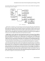
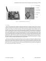
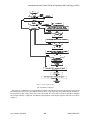
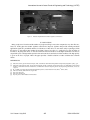
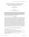
International Journal of Latest Trends in Engineering and Technology (IJLTET)
Implementation of Modern Vigilance Control
Device Using GSM and GPS Technology
Ch.Sindhura
Department of Electronics and Communication Engineering
Gudlavalleru Engineering College, Gudlavalleru, Andhra Pradesh, India
B.R.B.Jaswanth
Assistant Professor, Department of Electronics and Communication Engineering
Gudlavalleru Engineering College, Gudlavalleru, Andhra Pradesh, India
Abstract- This paper is proposed to prevent train accidents (due to un-alertness of engine drivers) by designing engines
with a new emergency braking system— Modern VCD (Vigilance Control Device), a microcontroller based safety device
which will enhance passenger’s safety by cyclically generating warnings and by automatically stopping the train if the
driver is incapacitated or dead or fast asleep. This paper also informs the position of the loco crew to the higher
authorities and tracks the position of the train where it is stopped by using Global System for Mobile communication
(GSM) and Global Positioning System (GPS) technologies. If the driver does not perform a regular task such as
accelerating or braking for a stipulated period of time a message will be send to the Vigilance Control Officer (VCO)
through GSM. After the train is stopped automatically, its position is tracked by GPS and a message will be send to the
Vigilance officer.
Keywords– Driver, Control, GPS, GSM, Loco, Vigilance, Warnings
I. INTRODUCTION
In Indian Railways, major accidents have been caused due to failure of Railway staff. Higher incidence of human
failures surface as technical safeguards and backups do not always replace the human effort. Though an accident
occurs only when both fail but it usually gets logged as ‘human error’ with a tendency of glossing over technical
failure. Under optimum field conditions and with the best of intentions, a human being is likely to commit a mistake
from time to time. This is the reason why operating rules included many redundancies in safety procedures and
operating practices involve number of checks and balances. More and more automation is resorted to prevent
human errors. This paper provides a method to safety of the passengers in trains by alerting the driver cyclically.
Vigilance control device plays a major role to reduce the accidents that are caused by the pilot of the train. Vigilance
Control Device (VCD) is a microcontroller based safety device which will automatically apply penalty brakes in
case the driver is incapacitated or dead. Similar operation is available in older locomotives in the form of Dead
man’s Lever. "The dead man's lever is a knob that has to be kept pressed at all times to keep the train running. This
system was introduced to prevent accidents, even if the driver died at his controls, hence the name. Unless a certain
amount of pressure is maintained on the lever, brakes get automatically activated and the train slows down and
comes to a stop. Another form of driver safety system is “Dead Man System” which detects a continuous input from
the driver, e.g. by application of force to a pedal or handle [1]. In this system there is no facility to inform the action
of the driver and the position of the train to higher authorities to take any responsible decision. So in order to
overcome this disadvantage and to make the driver in alertness and to ensure safety to passengers the new system is
proposed called modern vigilance control device.
The rest of the paper is organized as follows. The proposed setup of the system i.e., the block diagram and its
description are explained in section II. Experimental results are presented in section III. Concluding remarks are
given in section IV.
II. PROPOSED SYSTEM
A. Block Diagram and its description:
The proposed system consists of different components interfacing to a microcontroller. In this paper we are using
AT89S52 microcontroller, the heart of the system. The AT89S52 microcontroller is a low-power; high performance
CMOS 8-bit microcontroller with 8K bytes of in-system programmable flash memory and it is a powerful
Vol. 2 Issue 4 July 2013
403
ISSN: 2278-621X
International Journal of Latest Trends in Engineering and Technology (IJLTET)
microcontroller which provides a highly-flexible and cost-effective solution to many embedded control applications.
The block diagram is shown in Figure 1.
Figure 1. Block Diagram
The input power is step down to 5v DC from 230v AC power line by the power supply unit. LCD (Liquid Crystal
Display) screen is an electronic display module and find a wide range of applications. The JHD 16x2A LCD is used
and is connected to the output port of micro controller to display the cyclic operations of vigilance control device. The
microcontroller can communicate with the serial devices using its single serial port. The logic levels at which this
serial port operates is TTL logics. But some of the serial devices operate at RS 232 logic levels. So in order to
communicate the microcontroller with modem, a mismatch between the logic levels occurs. In
order to avoid this mismatch, in other words to match the Logic levels, a serial driver is used. A MAX232 is a
serial line driver used to establish communication between modem and microcontroller.
A GSM modem is a wireless modem that works with a GSM wireless network. It operates at either the 900MHz or
1800MHz frequency band. It supports voice calls and data transfer speeds of up to 9.6kbits/s, together with the
transmission of SMS (Short Message Service). The GSM prototype is shown in Figure 2(a). The GSM Modem comes
with a serial interface which the modem can be controlled using AT command interface. Here a GSM modem
SIMCOM made SIM300 V 7.03 interfaced with the microcontroller operates in 900MHz frequency and is operated at
voltage levels of 3.5 to 5V. The working of GSM modem is based on commands, the commands always start with AT
(which means ATtention) and finish with a <CR> character. AT commands are used to control the MODEMs. Since
one of the main objective for this application is to show how to send the message, only a subset of the AT command
set needs to be implemented. The AT commands are given to the GSM modem with the help of PC or controller.
The Global Positioning System (GPS) is a satellite based navigation system that sends and receives radio signals. A
GPS receiver acquires these signals and provides the user with information. Using GPS technology one can determine
location, velocity and time, 24 hours a day, in any weather conditions anywhere in the world for free. The basis of the
GPS technology is a set of 24 satellites that are continuously orbiting the earth. These satellites are equipped with
atomic clocks and sent out radio signals as to the exact time and location. These radio signals from the satellites are
picked up by the GPS receiver. Once the GPS receiver locks on to four or more of these satellites, it can triangulate its
location from the known positions of the satellites. It is a higher performance, low power satellite based model. It is a
cost effective and portable system which accurately detects the location. The GPS receiver used here is Sky Traq
Venus 6 GPS module ST22 which is having TTL logics and also RS232 as option. The GPS receiver is shown in
Figure 2(b). This GPS is used to track the position of the train after the emergency brake is applied in order to avoid
the accidents. This application is used only after the train is stopped.
Vol. 2 Issue 4 July 2013
404
ISSN: 2278-621X
International Journal of Latest Trends in Engineering and Technology (IJLTET)
(a)
(b)
Figure 2. (a) GSM Modem Prototype (b) GPS Receiver
B. Working:
VCD is microcontroller based equipment designed and manufactured to enhance the safety of the locomotive
operation by ensuring the alertness of the crew all the time. The system is resetting type and operates in a fail-safe
manner. VCD will give cyclic warnings to the driver. Based on the drivers reaction to these warnings (in terms of
pre-defined set of actions to be done by the driver), the system will automatically reset the alerting cycle. The
locomotive driver operates controls for increasing and decreasing locomotive power application or releasing the
breaks or operating the horn of the locomotive. The VCD monitors whether these controls have been operated by the
driver in a 60-second time period. In case the driver has not operated any controls, the VCD gives a visual warning
by activating a flashing light for 8 seconds. If acknowledgement is not received, an additional audio alarm is given
for 8 sec. If driver further fails to acknowledge the alarm, a message is send to guard and to signal inspector through
GSM modem as “DRIVER IS NOT ALERT”, here guard is provided with break to control the VCD. If guard is not
applying break within 10 sec then message is sent to signal inspector as “DRIVER AND GUARD NOT ALERT”
and VCD will initiate the automatic application of brakes and it informs the position of the train where it is stopped
in the form of latitude and longitude through GSM by using GPS module.
MU mode is the multiple unit used when the efficiency of the one engine is not sufficient for pulling the trains in
hilly areas then it is provided for utilizing the efficiency of the second engine it is required to operate in mu mode.
When VCD is operated in MU mode the above operation of the VCD cycle should not be activated in the second
engine that is the driver is provided only in one cabin so it is programmed that when VCD operates in MU mode the
entire VCD cycle at second engine should not activate. The flow chart shown in Fig.2 gives the clear explanation of
the working of the modern vigilance control device.
Vol. 2 Issue 4 July 2013
405
ISSN: 2278-621X
International Journal of Latest Trends in Engineering and Technology (IJLTET)
Figure 3. Flow chart of the System
III. EXPERIMENTAL RESULT
This paper gives a different way of approaching the problem. The proposed system not only alert the loco pilot but
also informs the position of the pilot and also the train where it was stopped by using GSM and GPS technologies.
By using the flow chart in figure 2 the source code is developed. The source code is written in embedded C language
and is tested on Proteus 7.2 platform. The hardware implementation of the modern vigilance control device is shown
in figure 3.
Vol. 2 Issue 4 July 2013
406
ISSN: 2278-621X
International Journal of Latest Trends in Engineering and Technology (IJLTET)
Figure 4.
Hardware Implementation of modern vigilance control device
IV.CONCLUSION
Many people travel in trains and the number of people travelling is more when compared to any other like cars,
buses etc. In this paper the modern vigilance control device improves vigilance and provides warning and brake
application signals in a predefined manner. So with the use of this device we can ensure safety to passengers. With
this device we can analyze that whether the accident is due to loco pilot i.e., engine driver or due to failure of
locomotive. By using this device we can also inform the action of the driver to the higher authorities if he fails to
respond the cyclic warnings and the position of the train can also be tracked to avoid the accidents. The high priority
is given to the lives of people. Hence this paper provides a feasible solution to reduce accidents due to human
failure.
REFERENCES
[1]
[2]
[3]
[4]
[5]
[6]
[7]
ITSR, Driver Safety Systems Discussion Paper, 2006, Australia/New South Wales Independent Transport Safety Regulator: Sydney, p.32.
Santosh B. Patil, Rupal M. Walli, “Design and Development of Fully Automatic AT89C52 Based Low Cost Embedded System For Rail
Tracking”, International Journals of Electronics, Communication and Soft Computing Science and Engineering (IJECSCSE), Vol.1,Issue
1,Pg 9-14.
M. A. Mazidi, “The 8051 Microcontroller & Embedded Systems”, Pearson Education Asia, India, 2nd edition, 2008.
GSM User Manual, SIMCOM LTD, August 2006.
http://www.atmel.com
http://www.simcom.com
Sky Traq Venus 6 GPS Module ST22 Data Sheet.
Vol. 2 Issue 4 July 2013
407
ISSN: 2278-621X