1
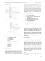
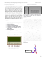
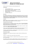
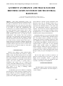
Global Journal of Advanced Engineering Technologies, Vol3, Issue3-2014
ISSN: 2277-6370
ACCIDENT AVOIDANCE AND TRACK FAILURE
IDENTIFICATION SYYTEM IN SOUTH CENTRAL
RAILWAYS
1,2,3
M. Naga Sai Nikhil1, M.Venkata Krishnakanth2, S.Venkata Naga Siva3,
B.Tech student , V.R.Siddhartha Engineering college, Andhra Pradesh,India.
Abstract: - Track failure identification system is an
advanced method used to identify the track failure and send
the signal is transmitted to alert the train driver who is
passing through that way in this project the track failure
can be identified by using IR sensors and send the signals
to the driver by using RF Communication. RF
communication is very efficient communication for sending
the signals immediately. Radio frequency (RF) is widely
used technology in wireless communications .the RF
module is an Electronic circuit it involves two sub units
named transmitter and receiver to provide the wireless
communication. Train accidents have been increased
rapidly due to the track failures because the detection of
track failure is taking time and also sending a message
about the track failure to the driver and appropriate action
to be taken by drivers becomes delayed. This project is
aimed to detect the track failure conditions using IR and
sending the signals to the driver if any track is failed the RF
transmitter sends the signal to the receiver. In train section
the alarm will be on, and also display the track failure
information by using LCD.
.
I. INTRODUCTION
Security is the condition of being protected against
danger or loss. In the general sense, security is a concept
similar to safety. The nuance between the two is an added
emphasis on being protected from dangers that originate
from outside. Individuals or actions that encroach upon the
condition of protection are responsible for the breach of
security. The word "security" in general usage is
synonymous with "safety," but as a technical term
"security" means that something not only is secure but that
it has been secured. One of the best options for providing
good security is by using a technology named
EMBEDDED SYSTEMS.
An Embedded system can be defined as a computing
device that does a specific focused job. Appliances such as
the air-conditioner, VCD player, DVD player, printer, fax
machine, mobile phone etc. are examples of embedded
systems. Each of these appliances will have a processor and
special hardware to meet the specific requirement of the
application along with the embedded software that is
executed by the processor for meeting that specific
requirement. The embedded software is also called “firm
ware”. The desktop/laptop computer is a general purpose
computer. You can use it for a variety of applications such
as playing games, word processing, accounting, software
development and so on. In contrast, the software in the
embedded systems is always fixed listed below,
Embedded systems do a very specific task; they cannot
be programmed to do different things. Embedded systems
have very limited resources, particularly the memory.
Generally, they do not have secondary storage devices such
as the CDROM or the floppy disk. Embedded systems have
to work against some deadlines. A specific job has to be
completed within a specific time. In some embedded
systems, called real-time systems, the deadlines are
stringent. Missing a deadline may cause a catastrophe-loss
of life or damage to property. Embedded systems are
constrained for power. As many embedded systems operate
through a battery, the power consumption has to be very
low.
The rest of the paper is as follow. In Section 2, we
explain the proposed setup of the system i.e., the block
diagram and its description. Section 3 explains the
working of the proposed system. We conclude the paper
in Section 4 describing our accomplishments.
II. PROPOSED METHOD
The block diagram consists of different components
interfacing to a microcontroller. The block diagram is
shown in Figure1.
288
Global Journal of Advanced Engineering Technologies, Vol3, Issue3-2014
Transmitter section:
ISSN: 2277-6370
standard 80C51 and 80C52 instruction set and pin out.
The on-chip Flash allows the program memory to be
reprogrammed in-system or by a conventional
nonvolatile memory programmer. By combining a
versatile 8-bit CPU with in-system programmable Flash
one monolithic chip, the Atmel AT89S52 is a powerful
micro- controller which provides a highly-flexible and
cost-effective solution to many embedded control
applications.
Features of the microcontroller:
Figure 1: Block Diagram
Receiver section:
· It is a 8-bit microcontroller.
· 8K Bytes of In-System Programmable (ISP)
Flash Memory.
· -Endurance: 1000 Write/Erase Cycles
· Fully Static Operation: 0 Hz to 33 MHz
· 256 x 8-bit Internal RAM.
· 32 Programmable I/O Lines.
· Three 16-bit Timer/Counters.
· Eight Interrupt Sources.
· Full Duplex UART Serial Channel.
B) Power Supply:
The various components in the block diagram are
mentioned below:
1.
2.
3.
4.
5.
6.
7.
8.
9.
10.
11.
AT89S52 Microcontroller
Power Supply
Crystal Oscillator
Reset
16x2 Liquid Crystal Display(LCD)
RF receiver
Decoder
RF Transmitter
Buzzer
Decoder
IR sensor
A) Microcontroller Unit
The AT89S52 is a low-power, high performance
CMOS 8- bit microcontroller with 8K bytes of insystem programmable Flash memory. The device is
manufactured using Atmel’s high-density nonvolatile
memory technology and is compatible with the industry
The input to the circuit is applied from the regulated
power supply. The microcontroller voltage is of 5V. The
A.C. input i.e., 230V from the mains supply is step
down by the transformer to 12V and is fed to a
rectifier. The output obtained from the rectifier is a
pulsating D.C voltage. So in order to get a pure D.C
voltage, the output voltage from the rectifier is fed to a
filter to remove any A.C components present even after
rectification. Now, this voltage is given to a voltage
regulator to obtain a pure constant dc voltage. We are
using an IC 7805 as voltage regulator to get a 5V
output Voltage.
C) Crystal Oscillator
A crystal oscillator is an electronic oscillator
circuit that uses the mechanical resonance of a vibrating
crystal of piezoelectric material to create an electrical
signal with a very precise frequency. This frequency is
commonly used to keep track of time (as in quartz wrist
watches), to provide a stable clock signal for digital
integrated circuits, and to stabilize frequencies for
radio transmitters and receivers. The most common
type of piezoelectric resonator used is the quartz
crystal, so oscillator circuits designed around them
became known as “crystal oscillators”. This block
provides necessary frequency sine wave to the micro
controller. This frequency is converted to square wave
within the micro controller.
D) Reset
Control reset is to execute the entire program cycle
from beginning.
289
Global Journal of Advanced Engineering Technologies, Vol3, Issue3-2014
E) Liquid Crystal Display (LCD)
LCD (Liquid Crystal Display) screen is an electronic
display module and find a wide range of applications. A
16x2 LCD means it can display 16 characters per line and
there are 2 such lines. In this JHD 16x2A LCD each
character is displayed in 5x7 pixel matrix. The schematic
diagram of 16x2 LCD is shown in Fig.2. This LCD has
two registers, namely, Command and Data. The
command register stores the command instructions
given to the LCD. A command is an instruction given
to LCD to do a predefined task like initializing it,
clearing its screen, setting the cursor position, controlling
display etc. The data register stores the data to be
displayed on the LCD. The data is the ASCII value of
the character to be displayed on the LCD. Some of
the LCD command codes are listed in Table 1.
Features:
·
·
·
·
·
·
·
·
·
·
Interface with either 4-bit or 8-bit microprocessor.
Display data RAM.
80x8 bits (80 characters).
Character generator ROM and RAM.
160 different 5x7 dot-matrix character patterns.
8 different users programmed 5x7 dotmatrix patterns.
Numerous instructions.
Clear Display, Cursor Home, Display ON/OFF,
Cursor.
ON/OFF, Blink Character, Cursor Shift, Display
Shift.
Built-in reset circuit is triggered at power ON.
ISSN: 2277-6370
Table 1: LCD Command Codes
Code(Hex)
01
06
Command to LCD Instruction Register
Clear display of the screen
Automatic increment
38
2 line 5x7 Matrix
0F
Display is on and the cursor blinks
80
Force Cursor to begin from 1’st line
C0
Force Cursor to begin from 2nd line
The LCD display is connected to the output port of
micro controller to display the cyclic operations of
vigilance control device.
F) Buzzer
A buzzer or beeper is a signaling device, usually
electronic, typically used in automobiles, household
appliances such as a microwave oven, or game shows. It
most commonly consists of a number of switches or sensors
connected to a control unit that determines if and which
button was pushed or a preset time has lapsed, and usually
illuminates a light on the appropriate button or control
panel, and sounds a warning in the form of a continuous or
intermittent buzzing or beeping sound. Initially this device
was based on an electromechanical system which was
identical to an electric bell without the metal gong (which
makes the ringing noise). Often these units were anchored
to a wall or ceiling and used the ceiling or wall as a
sounding board. Another implementation with some ACconnected devices was to implement a circuit to make the
AC current into a noise loud enough to drive a loudspeaker
and hook this circuit up to a cheap 8-ohm speaker. Now-adays, it is more popular to use a ceramic-based piezoelectric sounder like a Sonalert which makes a high-pitched
tone. Usually these were hooked up to driver” circuits
which varied the pitch of the sound or pulsed the sound on
and off.
Buzzer Driver:
VCC
12 V
+
Buz
-
Figure 2: Schematic diagram of 16×2 LCD
µC PORT
D?
4007
Q?
BC547
290
Global Journal of Advanced Engineering Technologies, Vol3, Issue3-2014
The circuit is designed to control the buzzer. The buzzer
ON and OFF is controlled by the pair of switching
transistors (BC 547). is conducting and close the collector
and emitter terminal so zero signals is given to base of the
Q2 transistor. Hence Q2 transistor and buzzer is turned
OFF state.
When low pulse is given to base of transistor Q1, the
transistor is turned OFF. Now 12V is given to base of Q2
transistor so the transistor is conducting and buzzer is
energized and produces the sound signal.
G) HT12E ENCODER:
General Description: The 212 encoders are a series of
CMOS LSIs for remote control system applications. They
are capable of encoding information which consists of N
address bits and 12_N data bits. Each address/data input
can be set to one of the two logic states. The programmed
addresses/ data are transmitted together with the header bits
via an RF or an infrared transmission medium upon receipt
of a trigger signal. The capability to select a TE trigger on
the HT12E or a DATA trigger on the HT12A further
enhances the application flexibility of the 212 series of
encoders. The HT12A additionally provides a 38 kHz
carrier for infrared systems.
Features:
·
·
·
·
·
·
·
·
·
·
·
·
Operating voltage
2.4V~5V for the HT12A
2.4V~12V for the HT12E
Low power and high noise immunity CMOS
technology
Low standby current: 0.1_A (typ.) at VDD=5V
HT12A with a 38kHz carrier for infrared
transmission medium
Minimum transmission word
Four words for the HT12E
One word for the HT12A
Built-in oscillator needs only 5% resistor
Data code has positive polarity
Minimal external components
Pair with Holtek_s 212 series of decoders
18-pin DIP, 20-pin SOP package
Applications
·
·
·
·
·
·
·
·
ISSN: 2277-6370
Garage door controllers
Car door controllers
Car alarm system
Security system
Cordless telephones
Other remote control systems
H) HT12D DECODER:
The 212 decoders are a series of CMOS LSIs for
remote control system applications. They are paired with
Holtek_s 212 series of encoders (refer to the
encoder/decoder cross reference table). For proper
operation, a pair of encoder/decoder with the same number
of addresses and data format should be chosen. The
decoders receive serial addresses and data from a
programmed 212 series of encoders that are transmitted by
a carrier using an RF or an IR transmission medium. They
compare the serial input data three times continuously with
their local addresses. If no error or unmatched codes are
found, the input data codes are decoded and then
transferred to the output pins. The VT pin also goes high to
indicate a valid transmission. The 212 series of decoders
are capable of decoding information’s that consist of N bits
of address and 12_N bits of data. Of this series, the HT12D
is arranged to provide 8 address bits and 4 data bits, and
HT12F is used to decode 12 bits of address information.
Features
·
·
·
·
·
·
·
·
·
·
·
·
·
·
Operating voltage: 2.4V~12V
Low power and high noise immunity CMOS
technology
Low standby current
Capable of decoding 12 bits of information
Binary address setting
Received codes are checked 3 times
Address/Data number combination
HT12D: 8 address bits and 4 data bits
HT12F: 12 address bits only
Built-in oscillator needs only 5% resistor Valid
transmission indicator
Easy interface with an RF or an infrared
transmission medium
Minimal external components
Pair with Holtek_s 212 series of encoders
18-pin DIP, 20-pin SOP package
Burglar alarm system
Smoke and fire alarm system
291
Global Journal of Advanced Engineering Technologies, Vol3, Issue3-2014
Functional Description: Operation
The 212 series of decoders provides various
combinations of addresses and data pins in different
packages so as to pair with the 212 series of encoders. The
decoders receive data that are transmitted by an encoder
and interpret the first N bits of code period as addresses and
the last 12_N bits as data, where N is the address code
number. A signal on the DIN pin activates the oscillator
which in turn decodes the incoming address and data. The
decoders will then check the received address three times
continuously. If the received address codes all match the
contents of the decoder local address, the 12_N bits of data
are decoded to activate the output pins and the VT pin is set
high to indicate a valid transmission. This will last unless
the address code is incorrect or no signal is received. The
output of the VT pin is high only when the transmission is
valid. Otherwise it is always low.
Applications
·
·
·
·
·
·
·
·
Burglar alarm system
Smoke and fire alarm system
Garage door controllers
Car door controllers
Car alarm system
Security system
Cordless telephones
Other remote control systems
III. SIMULATION AND MODELING
Traditionally circuit simulation has been a non
interactive affair. In the early days net list were prepared by
hand, and output considered of reams of numbers.
Proteus Simulation Software:
Proteus Virtual System Modeling (VSM) combines mixed
mode SPICE circuit simulation, animated components and
microprocessor models to facilitate co simulation of
complete micro-controller based designs. For the first time
ever, it is possible to develop and test such designs before a
physical prototype is constructed. This is possible because
one can interact with the design using on screen indicators
such as LED and LCD displays and actuators such as
switches and buttons. The simulation takes place in real
time (or near enough to it): a 300 MHz Pentium II can
simulate a basic 8051 system clocking at over 12MHz.
Proteus VSM also provides extensive debugging facilities
ISSN: 2277-6370
including breakpoints, single stepping and variable display
for both assembly code and high level language source.
IV. CONCLUSION
In this paper, an automatically Track failure
identification system is designed and simulated. The
simulation has been done using proteus and testing has
been carried out using the developed prototype. This
method of track failure Identification system is enormous
and very applicable. It is even advantageous to avoid the
train accidents in south central railways and efficient way to
find out the track failure conditions.
REFERENCES
[1] ITSR, Driver Safety Systems Discussion Paper,
2006, Australia/New South Wales Independent
Transport Safety Regulator: Sydney, p.32.
[2] Whitlock, Driver vigilance devices: systems review
(and RSSB response) 2002, Rail Safety and
Standards Board/Quintec, p.105.
[3] Santosh B. Patil, Rupal M. Walli, “Design and
Develop- ment of Fully Automatic AT89C52 Based
Low Cost Embedded System For Rail Tracking”,
International
Journals
of
Electronics,
Communication and Soft Computing Science and
Engineering (IJECSCSE), Vol.1, Issue 1,Pg 9-14.
[4] M. A. Mazidi, “The 8051 Microcontroller &
Embedded Systems”, Pearson Education Asia,
nd
India, 2 edition, 2008.
[5] Raj Kamal, “Embedded System- Architecture,
Program- ming and Design”, Tata McGraw Hill
nd
[6]
[7]
[8]
[9]
Publisher, 2 edition, 2008.
GSM User Manual, SIMCOM LTD, August 2006.
http://www.atmel.com
http://www.simcom.com
Sky Traq Venus 6 GPS Module ST22 Data Sheet.
292