1
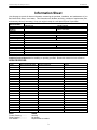
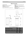
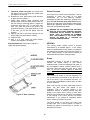
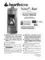
(Model 8180)
Gas Fired Direct-Vent Heater
Owner's Manual
INSTALLATION AND
OPERATING INSTRUCTIONS
PLEASE READ THIS ENTIRE OWNER’S
MANUAL BEFORE YOU INSTALL AND USE
YOUR NEW BARI GAS HEATER. SAVE THIS
DOCUMENT FOR FUTURE REFERENCE.
WARNING: FOLLOW THE INFORMATION IN THESE
INSTRUCTIONS EXACTLY, IF NOT, A FIRE OR
EXPLOSION MAY RESULT CAUSING PROPERTY
DAMAGE, PERSONAL INJURY OR LOSS OF LIFE.
WARNING: DO NOT STORE OR USE GASOLINE
OR ANY OTHER FLAMMABLE VAPORS AND
LIQUIDS NEAR THIS OR ANY OTHER GAS
APPLIANCE.
WHAT TO DO IF YOU SMELL GAS:
Do not try to light any appliance.
Do not touch electrical switches; do not use the phone
in your building.
Immediately call your gas supplier from a phone
outside the structure. Follow your gas supplier’s
instructions.
If you cannot reach your gas supplier, call the fire
department or 911.
A qualified installer, service agency, or gas supplier must
perform installation and service of this appliance. In the
Commonwealth of Massachusetts, all installation of gas
lines and gas fittings must be performed by a licensed gas
fitter or licensed plumber.
AVERTISSEMENT: ASSUREZ-VOUS DE BIEN
SUIVRE LES INSTRUCTIONS DONNÉ DANS CETTE
NOTICE POUR RÉDUIRE AU MINIMUM LE RISQUE
D’INCENDIE OU POUR ÉVITER TOUT DOMMAGE
MATÉERIEL, TOUTE BLESSURE OU LA MORT.
AVERTISSEMENT: NE PAS ENTRESPOSER NI
UTILISER D’ESSENCE NI D’AUTRE VAPERURS OU
LIQUIDES INFLAMMABLES DANS LE VOISINAGE
DE CET APPRAREIL OU DE TOUT AUTRE
APPAREIL.
QUE FAIRE SI VOUS SENTEZ UNE ODEUR DE GAZ:
Ne pas tenter d’allumer d’appareil.
Ne touchez à aucun interrupteur. Ne pas vous servir
des téléphones se trouvant dans le batiment où vous
vous trouvez.
Appelez immédiatement votre fournisseur de gaz
depuis un voisin.
Suivez les instructions du
fournisseur.
Si vous ne pouvez rejoindre le fournisseur de gaz,
appelez le service dos incendies.
L’installation et service doit être exécuté par un qualifié
installer, agence de service ou le fournisseur de gaz.
Bari DV Gas Model 8180
Manual # 6400-40458
R: 4 - 6/30/2011
Hearthstone Quality Home Heating Products, Inc.
Bari Model #8180
Intentionally Blank
2
Hearthstone Quality Home Heating Products, Inc.
Bari Model #8180
Information Sheet
Use this page to record all relevant information concerning the purchase, installation, and maintenance of your
Bari Model 8180 Direct -Vent heater. This information will facilitate servicing, purchase of replacement parts,
and warranty claims (if necessary). Keep your original receipt in a safe place as proof of purchase.
Serial Number:
Fuel type:
Natural Gas
Liquid Propane
Sold by:
Address:
Phone:
E-mail
Date of Purchase:
Website:
Installed by:
Address:
Phone:
E-mail
Date of Installation:
Website:
Gas Supplier:
Address:
Phone:
E-mail
Website:
Read this Owner’s Manual before installing or operating your Bari. Retain this manual for future reference.
SERVICE RECORD
Date
Who Performed Work
WHAT
Firebox Cleaning.............
Glass Cleaning................
Door Gasket....................
Work Performed
WHEN
annually
as needed
Replacement as needed
3
Notes:
Hearthstone Quality Home Heating Products, Inc.
Bari Model #8180
Table of Contents
INTRODUCTION .......................................................................................................................... 5
SPECIFICATIONS ........................................................................................................................ 6
OWNER’S INFORMATION ............................................................................................................. 7
DAILY OPERATION ................................................................................................................................................. 7
SERVICE CAUTION ................................................................................................................................................. 7
FUEL GAS ............................................................................................................................................................. 7
INSTALLER’S INFORMATION ........................................................................................................ 8
CODES ................................................................................................................................................................. 8
INSTALLATION PREPARATION...................................................................................................... 9
HEARTH REQUIREMENT / FLOOR PROTECTION ........................................................................................................ 9
CLEARANCE TO COMBUSTIBLES ............................................................................................................................. 9
OPENING THE FRONT DOOR .................................................................................................................................. 9
INSTALLING THE STONE PANELS............................................................................................................................. 9
VENTING INFORMATION ............................................................................................................ 12
VENT CONNECTION ............................................................................................................................................. 12
RESTRICTOR PLATE ............................................................................................................................................ 12
VENTING COMPONENTS & CONFIGURATION .......................................................................................................... 14
ELECTRICAL CONNECTIONS ...................................................................................................... 16
GAS SUPPLY & CONNECTIONS ................................................................................................. 17
FIRE LOG PLACEMENT ............................................................................................................. 18
OPERATION ............................................................................................................................. 20
LIGHTING THE UNIT FOR THE FIRST TIME .............................................................................................................. 20
PILOT LIGHT ........................................................................................................................................................ 20
PREPARE FOR LIGHTING ...................................................................................................................................... 20
INITIAL ADJUSTMENTS.......................................................................................................................................... 20
LIGHTING INSTRUCTIONS ..................................................................................................................................... 21
AIR SHUTTER ADJUSTMENTS ............................................................................................................................... 22
PILOT ADJUSTMENT ............................................................................................................................................. 22
ROUTINE MAINTENANCE AND CARE........................................................................................... 24
GLASS REPLACEMENT PROCEDURES: ................................................................................................................... 24
VENTING ............................................................................................................................................................. 25
OTHER INSTALLATIONS ............................................................................................................ 26
BOLTING YOUR BARI GAS TO A PERMANENT STRUCTURE ...................................................................................... 26
HIGH ALTITUDE INSTALLATIONS ............................................................................................................................ 26
PARTS LIST ............................................................................................................................. 27
TROUBLESHOOTING ................................................................................................................. 28
SAFETY RATING LABEL ............................................................................................................ 31
4
Hearthstone Quality Home Heating Products, Inc.
Bari Model #8180
INTRODUCTION
Congratulations on your purchase of Hearthstone’s
Bari Gas-Fired Direct Vent heater. The Bari will
provide you with clean, efficient heat for years to
come. Combustion air comes directly from the
outside of your home to the sealed firebox system,
eliminating the potential for annoying back drafts or
other
problems
associated
with
home
depressurization.
HOT SURFACES
Certain exposed surfaces of the Bari will reach high
temperatures during normal operation. Clearances
to combustibles must be maintained, as specified in
the “Clearances to Combustibles” section of this
manual.
DO NOT USE THIS APPLIANCE IF ANY PART
WAS UNDER WATER. IMMEDIATELY CALL A
QUALIFIED SERVICE TECHNICIAN TO INSPECT
THE HEATER AND TO REPLACE ANY PART OF
THE CONTROL SYSTEM AND GAS CONTROL
THAT HAS BEEN UNDER WATER. (NE PAS SE
SERVIR DE CET APPAREIL S’IL A ÉTÉ PLONGÉ
DANS L’EAU, COMPLÉTEMENT OU EN PARTIE.
APPELER UN TECHNICIEN QUALIFIÉ POUR
INSPECTOR L’APPAREIL ET REMPLACER TOUTE
PARTIE DU SYSTÉME DE CONTRÔLE ET TOUTE
COMMANDE QUI ONT ÉTÉ PLUNGES DANS
L’LAU.)
The Bari will provide you with many years of
practical and convenient service. However, as with
any gas appliance, the unit must be properly and
safely installed and maintained by qualified service
personnel to ensure safe and trouble-free operation.
READ THIS OWNER’S MANUAL
Operate and maintain this gas heater according to
the instructions in this manual. For your safety, and
years of trouble free operation, read this manual in
its entirety.
By following a few simple safety
precautions
and
by
performing
minimal
maintenance, the unit will remain appealing while
providing years of quality performance.
WARNING: THIS GAS APPLIANCE MUST NOT BE
CONNECTED TO A CHIMNEY FLUE SERVING A
SEPARATE VENTED APPLIANCE. NEVER VENT
THE GAS HEATER TO OTHER ROOMS OR
BUILDINGS. MASONRY CONVERSIONS KITS ARE
AN ACCEPTABLE VENTING OPTION.
WARNING: ENSURE ONLY A QUALIFIED
SERVICE TECHNICIAN INSTALLS, AND REPAIRS
THIS APPLIANCE. A QUALIFIED SERVICE
TECHNICIAN MUST INSPECT THE APPLIANCE
BEFORE USE, AND AT LEAST ANNUALLY. MORE
FREQUENT CLEANING MAY BE REQUIRED DUE
TO EXCESSIVE LINT FROM CARPETING,
BEDDING MATERIAL, PETS, ETC. IT IS
IMPERATIVE
THAT
THE
CONTROL
COMPARTMENTS, BURNERS, AND CIRCULATING
AIR PASSAGES OF THE APPLIANCE ARE KEPT
CLEAN
AND
FREE
OF
OBSTRUCTIONS.
(S’ASSURER QUE LE BRÛLEUR ET LE
COMPARTIMENT DES COMMANDES SONT
PROPRES.
VOIR
LES
INSTRUCTIONS
D’INSTALLATION
ET
D’UTILISATION
QUI
ACCOMPAGNENT L’APPAREIL.)
Due to high temperatures, locate the appliance out
of traffic and away from furniture, draperies, clothing
and flammable materials. Alert children and adults
to the hazards of high surface temperatures and to
stay away to avoid burns to skin or clothing ignition.
Ensure young children are carefully supervised
when in the same room as the appliance. Do not
place clothing or other flammable material on or
near the appliance. (Surveille les enfants. Garder
les vêtements, les meubles, l’essence ou autres
liquides à vapeur inflammables lin de l’appareil.)
FIRE HAZARD
WARNING: DO NOT OPERATE THIS APPLIANCE
WITH THE GLASS, OR ANY PANEL REMOVED,
CRACKED, OR BROKEN. DO NOT SUBJECT THE
DOOR TO ABUSE, SUCH AS STRIKING OR
SLAMMING SHUT. REPLACEMENT OF THE
GLASS PANEL SHOULD BE DONE BY A
LICENSED OR QUALIFIED SERVICE PERSON.
Do not store or use gasoline or other flammable
vapors or liquids in the vicinity of this appliance.
Locate the Bari out of traffic and away from furniture,
draperies, clothing, and flammable material.
NEVER BURN PAPER, WOOD OR OTHER
MATERIALS
This gas heater is designed to burn natural gas, or
when converted, liquid propane (LP). Never burn
any fuel not intended for use with this unit.
5
Hearthstone Quality Home Heating Products, Inc.
Bari Model #8180
SPECIFICATIONS
Model: Bari Direct-Vent Gas Fireplace Heater
(#8180)
Testing Agency: Intertek Testing Services
Tested to: ANSI Z21.88b-2005/CSA 2.33b-2005,
CGA 2.17-M91
Report No. 3109401-T1
Certified for US and Canada. Approved for Mobile
Home Installation
Certified for use by:
Board of State Examiners of Plumbers and
Gasfitters
100 Cambridge Street, Room 1511
Boston, Massachusetts 02202
LISTED AS: Gas-Fired Direct-Vent Fireplace Heater
Figure 1: Bari DV Model 8180 Dimensions
Specification
INPUT RATING (Btu/hr) 0-2000 ft
INPUT RATING (Btu/hr) 2000-4000 ft
ORIFICE SIZE (DMS) 0-2000 ft
ORIFICE SIZE (DMS) 2000-4500ft)
MANIFOLD PRESSURE - LO SETTING (in. W.c./kpa)
MANIFOLD PRESSURE - HI SETTING (in. W.c./kpa)
MINIMUM INLET PRESSURE - (in.w.c./kpa)
MAXIMUM INLET PRESSURE- (in.w.c./kpa)
MINIMUM INPUT RATING (btu/hr)
MAXIMUM OUTPUT (btu/hr) 0-2000 ft
6
NG
26,500
26,500
38
38
1.2/0.3
3.5/0.87
5.0/1.24
7.0/1.74
16,000
19,600
LP
26,500
26,000
52
53
3.3/0.8
10.0/2.48
11.0/2.88
13.0/3.22
15,000
20,100
Hearthstone Quality Home Heating Products, Inc.
Bari Model #8180
OWNER’S INFORMATION
The installation must conform with local codes or, in
the absences of local codes, the current National
Fuel Gas Code, ANSI Z223.1 (NFPA 54) or
CAN/CGA B149 Installation Code.
(Installer
l’appareil selon les codes ou règlements locaux, ou,
en l’absence de tels règlements, selon les Codes
d’installation CAN/CGA-B149.)
The Bari requires minimal routine maintenance and
care. Ensure the Bari is cool and off while cleaning,
or servicing.
Have qualified service personnel
inspect the unit, and venting system once a year to
insure that they are clean, free of obstructions, safe,
and in good working order.
If service or
maintenance is required, ensure qualified service
personnel perform it.
Contact your dealer for any necessary warranty
service.
SERVICE CAUTION
This stove is warranted by:
If you believe your Bari is in any way, not performing
properly, immediately discontinue operation until the
unit is inspected and approved by qualified service
personnel. Prior to servicing the unit, turn the valve
control knob clockwise to “OFF”. The unit should be
cool prior to servicing and cleaning. Use of any
components not supplied by Hearthstone on the
stove voids all warranties. Do not substitute
components.
Hearthstone Quality Home Heating Products, Inc®
317 Stafford Ave.
Morrisville, Vermont 05661
DAILY OPERATION
The Bari is easily operated by the homeowner once
installed and adjusted by qualified service
personnel. The unit can be controlled via the
programmable remote control during the heating
season. Set the remote transmitter to the desired
room temperature and the unit will cycle on and off
as required. By adjusting the variable output control
located on the gas control valve, the rate of heat
output can be varied to meet the heating
requirements of the season. Choosing a low flame
setting will result in longer burn cycles at a reduced
output, while choosing a high flame setting will result
in a shorter, hotter burn cycle. Through trial and
error, the homeowner can select the optimum flame
size for their setting and application.
CAUTION: REPLACE ANY SHIELD, DOOR, OR
SAFETY SCREEN COMPONENT REMOVED FOR
SERVICING, PRIOR TO OPERATING THE UNIT.
WARNING: FAILURE TO POSITION THE PARTS IN
ACCORDANCE WITH THESE DIAGRAMS OR
FAILURE
TO
USE
ONLY
THE
PARTS
SPECIFICALLY
APPROVED
WITH
THIS
APPLIANCE MAY RESULT IN PROPERTY
DAMAGE OR PERSONAL INJURY.
MOBILE HOME APPROVED
Conditionally approved for purchased mobile home
installation. This appliance may be installed in an
aftermarket, permanently located, manufactured
(mobile) home, where permitted by local codes.
During the summer non-heating season, switch the
remote receiver to “OFF”, and turn off the pilot. This
will improve the overall efficiency of the unit as the
heat from the pilot is wasted. When putting the unit
back into service, follow the lighting instructions
described on page 21.
FUEL GAS
When the unit is first lit, especially when cool, it is
normal to experience some condensation on the
inside of the window glass. This condensation will
evaporate within the first few minutes of operation. If
you note continuous condensation on the window
glass or dripping water from any part of the unit or
venting system (chimney), immediately discontinue
operation of the unit and contact qualified service
personnel.
This appliance is only for use with the type of gas
indicated on the rating plate. This appliance is not
convertible for use with other gases, unless a
certified kit is used, available through your local
Hearthstone dealer.
Clean the area around, under, and behind the unit
on a regular basis to prevent the accumulation of
dust and lint.
Cet appareil doit être utilisé uniquement avec les
types de gas indiqués sur la plaque signalétique. Ne
pas l’utiliser avec d’autres gas sauf si un kitde
conversion certifié est installé
Cet appareil peut être installé dans un maison
préfabriquée (mobile) déjà installée à demeure si les
règlements locaux le permettent.
7
Hearthstone Quality Home Heating Products, Inc.
Bari Model #8180
INSTALLER’S INFORMATION
CODES
Simpson Dura-Vent, Inc.
P.O. Box 1510
Vacaville, CA 95696-1510
Adhere to all local codes or, in their absence, the
latest edition of THE NATIONAL FUEL GAS CODE
ANSI Z223.1 (NFPA 54) or CAN/CGA B149.
Installation Code that can be obtained from:
American Metal Products (AmeriVent)
8601 Hacks Cross Rd.
Olive Branch, MS 38654
800-423-4270
AMERICAN NATIONAL STANDARDS INSTITUTE, INC.
1430 BROADWAY
NEW YORK, NY 10018
www.ansi.org
Selkirk Corporation
1301 W. President George Bush Hwy, Suite 330
Richardson, TX 75080-1139
800-992-8368
Security Chimneys International Ltd (Secure Vent)
2125 Monterey, Laval, Quebec
Canada, H7L 3T6
450-973-9999
OR
NATIONAL FIRE PROTECTION ASSOCIATION, INC.
BATTERY MARCH PARK
QUINCY, MA 02269
www.nfpa.org
ICC, Inc.
400 J-F Kennedy, St. Jerome, Quebec
Canada, J7Y 4B7
450-565-6336
A manufactured home (mobile) OEM installation
must conform to the Manufactured Home
Construction and Safety Standard, Title 24 CFR,
Part 3280 (U.S.) or Standard for Manufactured
Home Installation, ANSI/NCBCS A225.1 or Standard
for Gas Equipped Recreational Vehicles and mobile
Housing, CSA Z240.4.CAN/SCA Z240 MH
(Canada).
(Installer l’appareil selon les codes ou
règlements locaux, ou, en l’absence de tels
règlements,
selon
les
Codes
d’installation
CAN/CGA-B149.)
Metal-Fab, Inc.
P.O. Box 1138
Wichita, Kansas 67201
Unpack and Inspect for Damage The Bari is packaged to withstand normal shipment
without damage. However, damage can still occur
during transit; so take care to inspect for damage
when unpacking and installing the unit. If any
damage or missing parts are detected, immediately
contact your dealer.
Phillips head screwdriver
7/16-inch wrench
Other parts as required by
local code
*Safety Glasses
*Gloves
Do not install, or put into service, a damaged
or incomplete heater.
The Bari requires a pilot shield. This shield is
shipped with the unit. Ensure the shield is
installed over the pilot with the open end to
the left (when you are facing the front of the
unit).
*Recommended
PACKING LIST
1-Bari Gas-Fired Heater
1-Decorative Fire logs Set
1-Set Bari Stone Panels
1-Owner’s Manual
1-Warranty Validation
Form
316-943-2351
UNPACKING AND INSPECTION
ITEMS REQUIRED FOR INSTALLATION
External regulator (for LP)
Code Compliant Piping
Pipe sealant approved for
use with LP
Manual shutoff valve
Sediment trap (page 17)
Tee joint
Pipe wrench
800-835-4429
2-Accessory boxes
1-Venting/stove connector
1-Remote control receiver
1- Bag of Platinum Bright
Embers
Inspect the Bari for visible or concealed damage.
The unit should appear to be square and true, with
sheet metal parts smooth and free of bends and
dents. The painted surfaces should be free of
scratches flaking, or blemishes. If visible or
concealed damage is found or suspected, contact
your dealer for instructions.
Note: Vent kits and components are supplied separately.
Failure to use the venting components specified by
Hearthstone will void your warranty and could risk a fire.
Always use great care when handling the decorative
fire logs, as they are fragile and subject to damage
and breakage if handled roughly. If a broken log is
encountered, contact your dealer for replacement
logs. Otherwise, set the logs aside until called for
during the installation.
SPECIFIED VENTING MANUFACTURERS
The heater is approved for installation only with the
venting components provided by manufactures listed
on this page.
8
Hearthstone Quality Home Heating Products, Inc.
Bari Model #8180
INSTALLATION PREPARATION
BY
THIS
PRODUCT;
THEREFORE,
AN
ASSESSMENT MUST BE MADE BY THE
INSTALLER TO PREVENT CONSEQUENTIAL
DAMAGE OF WALLS AND FLOORING.
HEARTH REQUIREMENT / FLOOR
PROTECTION
You can place the Bari directly on any noncombustible surface, or wood floor. When installing
the Bari on carpet, vinyl, or any other combustible
floor other than wood flooring, it must be installed on
any non-combustible, or wood panel extending the
full width and depth of the stove.
OPENING THE FRONT DOOR
In order to gain access to the firebox you must open
the front door. The door has a handle on the side
that will latch the door shut; however there is also a
mounting screw on the lower right hand side that
locks the door in place. (See Figure 3) To access
this screw you must open the lower control door
located just below the front door. Before using the
latch, remove the mounting screw using a 4mm or
5/32” Allen wrench. Replace this screw when the
door is closed for operation, as the latch cannot
be relied on to maintain a proper permanent door
seal.
CLEARANCE TO COMBUSTIBLES
Due to high surface temperatures, install the unit out
of traffic and away from furniture and draperies. Do
not place clothing and other flammable material on
or near the heater. When positioning the unit always
maintain adequate clearances around air openings
into the combustion chamber and allow for adequate
ventilation. You must maintain minimum clearances
to combustibles as shown in the illustrations of this
section.
INSTALLING THE STONE PANELS
See the Stone Installation Instructions included in
the Manual Packet for specific information needed
for mounting the stones.
Ensure you consider the need for access to the gas
control valve access door on the front of the unit as
well as full access for periodic cleaning and
servicing.
Note: the stones on this stove are large and
heavy (150 pounds total).
CAUTION: THESE CLEARANCES REPRESENT
MINIMUM DISTANCES IN ALL CASES, WHICH,
THROUGH TESTING IN AN INDEPENDENT
LABORATORY TO ANSI AND CSA STANDARDS,
WILL PREVENT FIRE OR SPONTANEOUS
COMBUSTION. WE DO NOT CONTROL THE
COMBUSTIBLE MATERIALS EXPOSED TO HEAT
Use a second person to assist in mounting the
panels to avoid injury, or damage to the panels.
Despite the mass of each piece of soapstone, they
will break if dropped.
Figure 2 - Clearance to Combustibles
Figure 3 - Remove Screw for Firebox Access
9
Hearthstone Quality Home Heating Products, Inc.
Bari Model #8180
2” minimum vent pipe clearance to combustibles.
Figure 4: Minimum Vent Configuration and Clearances
10
Hearthstone Quality Home Heating Products, Inc.
Bari Model #8180
Figure 5: Termination Location & Clearances
A = Clearance above grade, veranda, porch, deck,
or balcony: 12 inches (30cm) minimum.
H = *Not to be installed within 15 feet (4.5m) above
a meter/regulator assembly within 3 feet (91cm)
horizontally from the center line of the regulator.
B = Clearance to window or door that may be
opened: **Min. 9 inches U.S./*12 inches (30cm)
CAN. We recommend 12 in, minimum to prevent
condensation on the window.
I = Clearance to service regulator vent: 3 feet (91cm)
J = Clearance to non-mechanical air supply inlet to
building or the combustion air inlet to any other
appliance: 12inches (30cm) minimum.
C = Clearance to permanently closed window: **Min.
9 inches, U.S./*12 inches (30cm) CAN.
K = Clearance to a mechanical air supply inlet:
**Min. 3 feet (91cm) above if within 10 feet
horizontally, U.S./*6 feet (1.83m) CAN minimum.
We recommend 12 in. minimum to prevent
condensation on the window.
D = Vertical clearance to ventilated soffit located
above the termination within a horizontal distance of
2 feet (60cm) from the center line of the termination:
18 inches (46cm) minimum.
L = ¹Clearance above paved sidewalk or a paved
driveway located on public property: 7 feet (2.1m)
minimum.
M = ²Clearance under veranda, porch, deck, or
balcony: 12 inches (30cm) minimum.
E = Clearances to unventilated soffit: 12 inches
(30cm) minimum.
*In accordance with CSA B149 Installation codes.
F = Clearance to outside corner: **Min. 9 inches,
U.S./12 inches (30cm) CAN. We strongly
recommend 12 inches, particularly where windy
conditions prevail.
**In accordance with the current ANSI Z223.1/NFPA 54,
National Fuel Gas Code. Note: Local Codes and
Regulations may require different clearances.
¹A vent shall not terminate directly above a sidewalk or
driveway which is located between two single family
dwellings and serves both dwellings
G = Clearance to inside corner: **Min. 6 inches,
U.S./12 inches (30cm) CAN. We strongly
recommend 12 inches, particularly where strong
winds prevail.
²Only permitted if veranda, porch, deck or balcony, is fully
open on a minimum of two sides beneath the floor.*
11
Hearthstone Quality Home Heating Products, Inc.
Bari Model #8180
VENTING INFORMATION
VENT CONNECTION
1. The Bari Direct Vent is approved for installation
only with the vent connecting components listed
in this manual. Use the following instructions
along with the pipe manufacturer’s instructions
to complete the installation.
2. Install the vent system according to the
manufacturer’s instructions.
OPEN
The venting system must be comprised of the
appropriate venting components as specified in this
manual.
RESTRICTOR PLATE
A vent restrictor plate adjusts the flow rate of
exhaust gases if necessary. This ensures proper
flame characteristics and efficiency for the wide
variety of vent configurations. Controlling the draft
also changes the aesthetics of the flame. The
restrictor plate consists of a rotating shutter in the
flue connector. This shutter is attached to a rod
that protrudes through the back of the pipe. This rod
has a lock nut attached. On the very end of the rod
is an indicator slot. This slot shows the relative
position of the restrictor shutter. If the slot is
pointing up and down (12+ 6 o’clock position) the
restrictor is open. If it is pointing left and right (9+3
o’clock, the restrictor is in the closed position. The
restrictor plate has unlimited settings. Depending
on the vent configuration, you may be required to
adjust the restrictor plate position (see Figure 8).
Once the desired position is reached, use a 7/16”
wrench to lock down the hex nut.
Figure 6: Restrictor in open position
CLOSED
Figure 7: Restrictor in closed position
12
Hearthstone Quality Home Heating Products, Inc.
Bari Model #8180
NOTE: These positions are based on lab results, and can have some variance.
Figure 8: Venting Configurations & Restriction Settings
13
Hearthstone Quality Home Heating Products, Inc.
Bari Model #8180
APPROVED VENTING SYSTEM COMPONENTS
VENTING COMPONENTS &
CONFIGURATION
(The following are components that are available, BUT NOT
necessary for all installations)
Do not vent the Bari jointly with any other solid fuel
or gas appliance. Vent the Bari directly to the
outside of the building using a proper termination as
listed in this manual. The only types of venting pipe
approved for use with your Bari Direct-Vent stove
are those listed in this manual. The venting
configuration diagram is shown in Figure 8. After
determining the proper venting configuration for your
stove, select the vent system that will accommodate
your installation.
90 0 Elbow
45 0 Elbow
6" Straight
9" Straight (Simpson only)
12" Straight
24" Straight
36" Straight
48" Straight
11"-14 5/8" Adjustable
Pipe
CAUTION: ENSURE NO WIRING OR PLUMBING IS
IN THE CHOSEN LOCATION.
CHIMNEY LINER SYSTEM
CAUTION: DO NOT RECESS VENTING
TERMINATIONS INTO A WALL OR SIDING.
Direct-Vent Chimney Liner Termination Kit
Chimney Liner Flex
Co-Linear Flex Connector
-Axial to Co-Linear Appliance Connect (Masonry
approved, not to exceed 16’ measured from the
stove top)
Note: If further direction is needed for installation,
please refer to the venting instructions, which are
provided with the venting components.
ACCEPTABLE DIRECT-VENT TERMINATION CAP
ROOF LOCATIONS
MINIMUM VENT KIT
Vent connector (Provided with unit)
24” Straight Pipe
90° elbow
12” Straight pipe
Wall Thimble Cover
Wall Thimble
Horizontal Vent Termination Cap
The vent/air intake termination clearances above the
high side of an angled roof are as follows:
Roof Pitch
Flat to 6/12
7/12 to 9/12
10/12 to 12/12
13/12 to 16/12
17/12 to 21/12
Feet
1
2
4
6
8
Vertical Vent Cap
36” Snorkel
Vinyl Siding Standoff 4” x
6 5/8"
Round Ceiling Support
Thimble Covers
Wall thimble
Horizontal Vent Cap
Meters
0.3
0.6
1.2
1.8
2.4
Dry fit your venting and take a measurement.
Pipe dimensions will vary by manufacturer
and supplier.
HORIZONTAL TERMINATION MINIMUM VENTING
KIT INSTALLATION INSTRUCTIONS
1. Install the 24” straight section on top of the vent
connector.
2. Place the 90° elbow on the 24” section. Facing
the direction expected to penetrate the wall.
3. Attach the 12” straight section to the 90° elbow.
Move the stove and pipe assembly backwards
until the 12” straight is flush against the wall. Pull
up on the pipe to ensure that there is a ¼” per
foot rise coming out of the stove to the wall.
4. Draw a circle around the pipe. Use the center of
this circle as the center point of the 10” x 10”
square wall pass through. Cut and frame the
wall pass through opening.
5. Place the interior wall thimble into the 10” x 10”
wall pass through. Secure it with 4 screws (not
Figure 9: Termination Cap clearances
14
Hearthstone Quality Home Heating Products, Inc.
Bari Model #8180
provided). Install the exterior portion of the
thimble in similar fashion, overlapping the 2
sections.
ensure a good seal between it and the wall.
Ensure the arrow on the end cap points up.
Secure the cap to the wall with appropriate
screws.
7. Move the stove and vent pipe into position.
Make sure the 12” vent pipe extends into the
horizontal vent cap a minimum of 1-1/4”. Secure
the vent using the straps from the horizontal
vent termination to the interior 6” pipe with 2
sheet metal screws, keeping the screws as
close to the wall thimble as possible. Bend or cut
any excess strapping, so that it is not visible
after the installation is complete.
CAUTION: FOR BUILDINGS WITH VINYL SIDING,
INSTALL A VINYL SIDING STANDOFF BETWEEN
THE VENT CAP AND THE EXTERIOR WALL.
6. Install the horizontal vent termination on the
outside of the wall. Ensure both of the retaining
straps extend through interior wall thimble.
Before attaching the vent termination to the
outside of the house, run a bead of nonhardening mastic around its’ outside edges to
15
Hearthstone Quality Home Heating Products, Inc.
Bari Model #8180
ELECTRICAL CONNECTIONS
NOTE: Open the valve compartment door on the
lower front of the unit to access electrical and gas
connections.
that may cause the temperature in the vicinity of the
thermostat to be unrepresentative of the room
temperature in general. Such influences might
include strong lighting, a heater vent from the central
heating system, or a nearby sunny or drafty window.
REMOTE CONTROL THERMOSTAT
The Bari 8180 comes equipped with a
programmable ON/OFF/Thermostat remote control.
We recommend the use of the thermostatic remote
for more comfortable performance, however you
may still override the thermostat by setting the
switch to “ON”. The thermostat controls the unit by
“calling for heat.” The thermostat turns the unit on
when the room is cold, and turns the unit off once
the room is warmed sufficiently. If desired, you can
use any wired wall thermostat in place of the remote.
You cannot use both the remote and a wall
thermostat simultaneously.
Do not place the thermostat transmitter directly
behind or too close to the unit, otherwise heat from
the unit will immediately satisfy the thermostat and
turn the unit off.
WIRING INSTRUCTIONS
CAUTION: LABEL ALL WIRES PRIOR TO
DISCONNECTION WHEN SERVICING CONTROLS.
WIRING ERRORS CAN CAUSE IMPROPER AND
DANGEROUS OPERATION. VERIFY PROPER
OPERATION AFTER SERVICING. (ATTENTION: AU
MOMENT DE L’ENTRETIEN DES COMMANDES,
ÉTIQUETEZ TOUS LES FILS AVANT LE
DÉBRANCHEMENT. DES ERREURS DE CÂBLAGE
PEUVENT
ENTRAÎUN
FONCTIONNEMENT
INADEQUATE ET DANGEREUX.) THE PROPER
LOCATION OF WIRE CONNECTIONS IS SHOWN
IN FIGURE 10 BELOW.
REMOTE THERMOSTAT PLACEMENT
Place the thermostat transmitter in the same room or
living space as the unit. Since the transmitter is the
device measuring the temperature, you will want to
keep it off the floor and away from any influences
Figure 10: Bari 8180 Wiring Diagram
16
Hearthstone Quality Home Heating Products, Inc.
Bari Model #8180
GAS SUPPLY & CONNECTIONS
Figure 11: Gas Control Valve
connections at pressures equal to, or greater than ½
psig.
NOTICE: A qualified technician must connect the
heater to the gas supply and leak test the unit
before it is approved for use. Consult all codes.
GAS PRESSURE ADJUSTMENT
WARNING: THE UNIT MUST BE INSTALLED AND
NOTE: A QUALIFIED TECHNICIAN
PERFORM THIS PROCEDURE!
CONNECTED IN ACCORDANCE WITH LOCAL
CODES, OR IN THE ABSENCE OF LOCAL CODES,
WITH THE MOST CURRENT EDITION OF THE
NATIONAL FUEL GAS CODE ANSI Z223.1 (NFPA
54) OR CAN/CGA B149 INSTALLATION CODE.
MUST
Once connected to the gas supply, the supply line
and manifold gas pressures must be tested. The
supply line pressure is tested to ensure it meets the
minimum gas supply pressure as listed in the
Specifications for the type of fuel in use (natural gas
or LP), by connecting a manometer to the supply
line and adjusting the incoming pressure if
necessary to meet the required supply line pressure
as listed in specifications. The manifold pressure tap
on the gas control valve, refer to Figure 11 for
location.
NFPA Code and Hearthstone require the use of a
dedicated sediment trap just upstream of the unit.
Damage to the valve or other components, due to
the lack of a sediment trap (figure 12), is not
covered by warranty.
GAS CONNECTIONS
The gas supply connection is made to the Bari’s gas
control valve at the middle, lower rear of the stove,
using a 3/8” male NPT fitting. The supply line
should be ½” diameter, or appropriately sized to
provide a sufficient gas supply to meet the maximum
demand of the unit without undue loss of pressure.
We recommend a flexible line to avoid undue
mechanical load on the valve and to ease thread
alignment, but refer to local codes.
CAUTION: CHECK FUEL GAS TYPE!
GAS SUPPLY
Isolate the Bari from the gas supply piping system
by closing its individual manual shutoff valve during
any pressure testing of the gas supply piping system
at test pressures equal to or greater than ½ psig.
Disconnect the Bari and its individual shut-off valve
from the piping system when testing the valve and
Figure 12: Typical Sediment Trap (required in all
installations)
17
Hearthstone Quality Home Heating Products, Inc.
BARI Model #8180
FIRE LOG PLACEMENT
CAUTION: FRAGILE! HANDLE LOG SET WITH
CARE. ALWAYS WEAR GLOVES AND SAFETY
GOGGLES WHILE HANDLING THE LOG SET.
Place only the Fire log set supplied with the Bari in
the firebox. Do not place any other logs, wood logs,
or other materials in the firebox. If the log set is
damaged or broken contact your dealer for
replacement. Only replace the logs with the same
approved replacement parts. These components
affect the combustion quality and safety of the
heater.
The Fire logs are durable; however, they will break if
subjected to rough or improper handling. Exact
positioning of the log set is required in order to
obtain a pleasing flame pattern and efficient
combustion. Incorrect log placement may cause
carbon build-up; excess thermal stress on the log
set and stove parts, reduced efficiency, and high
levels of carbon monoxide. If the log set does not fit
into the firebox exactly as outlined, contact your
dealer for assistance (see figure 3 for opening the
front door).
INSTALLATION OF THE FIRE LOG SET
2. Locate and install the rear right log.
Follow the order of the following photos in order to
install the log set:
3. Locate and install the ember pile. This will have
two holes underneath that fit over two posts in
the center of the burner top.
1. Install the rear left log in the rear left corner.
18
Hearthstone Quality Home Heating Products, Inc.
BARI Model #8180
7. Sprinkle the charcoal embers over the burner
ports only. Ensure that you leave the ports open
over the pilot and where the main burner ignites.
WARNING: DO NOT PLACE ANY CHARCOAL
EMBERS OR ROCK WOOL OVER THE BURNER
SCREEN!
4. Install the Center log. The bottom tip rests in the
cradle of the ember pile.
8. Place the twig as shown.
5. Place the left front ember strip in front of the pilot
assembly.
REMOVAL OF LOG SET
CAUTION: THE FIRE LOG SET RETAINS HEAT
AND CAN BE VERY HOT! ALLOW 2 TO 3 HOURS
AFTER PILOT LIGHT IS TURNED OFF BEFORE
HANDLING.
To remove the Fire log set, follow the Installation of
Log Set instructions in the reverse order.
6. Slide the Right front ember strip next to the Left
ember strip. The two fit together to hide the
seam.
19
Hearthstone Quality Home Heating Products, Inc.
BARI Model #8180
OPERATION
piezoelectric ignitor, discontinue operation; turn off
the gas to the gas control valve, and immediately
contact qualified service personnel for assistance.
LIGHTING THE UNIT FOR THE FIRST TIME
WARNING: IF YOU DO NOT FOLLOW THESE
INSTRUCTIONS
EXACTLY,
A
FIRE
OR
EXPLOSION MAY RESULT CAUSING PROPERTY
DAMAGE, PERSONAL INJURY OR LOSS OF LIFE.
PREPARE FOR LIGHTING
Prepare for the lighting procedure by adjusting the
thermostat (if equipped) to its lowest setting or OFF
position. If the gas control knob is not in the OFF
position, turn the knob fully clockwise to OFF. Locate
the variable output control knob and turn it fully
clockwise to the highest setting.
CAUTION: LIGHTING THE BARI FOR THE FIRST
TIME AND ADJUSTMENTS TO THE UNIT SHOULD
BE PERFORMED BY QUALIFIED SERVICE
PERSONNEL.
This appliance is designed only for use with the
type(s) of fuel gas indicated on the rating plate. This
appliance is not convertible for use with other gases,
unless a certified kit is used.
Prior to lighting the unit for the first time, wait 5
minutes to allow any residual gas within the unit to
dissipate. Smell all around the appliance area for
gas. Be sure to smell next to the floor because some
gases (LP) are heavier than air and will settle on the
floor. If you do not smell gas after this five-minute
period, proceed with the lighting procedure. If you do
smell gas, DO NOT proceed with the lighting
procedure. Instead, immediately refer to the What
to Do If You Smell Gas Warning, on the cover of
this manual.
Cet appareil doit être atilisé uniquement avec les
types de gas indiqués sur la plaque signalétique. Ne
pas l’utiliser avec d’autres gas sauf si un kited
conversion certifié est installé. )
SMOKE AND FUMES WARNING
When lit for the first time, the Bari will emit some
smoke and fumes. This is normal “off-gassing” of
the paints and oils used in the manufacturing and
assembly of the unit. Open windows to vent the
room if necessary. The off-gassing and fumes will
subside after the first 10 to 20 minutes of operation.
NOTE: The valve control has an interlock
device. After shutting off all gas flow, the pilot
burner cannot be relit until the thermocouple has
cooled, releasing the electromagnet (approx. 60
seconds). The gas control knob is designed to
operate by hand. Do not use any tools during
this operation. Damaged knobs may result in
serious injury.
ODORS AND IMPURITIES
A heater of this type may produce other odors during
heater operation due to impurities that may exist in
the immediate area. Sources of impurities can be
cleaning solvents, paint solvents, cigarettes,
candles, smoke, pet hair, dust, adhesives, new
carpet, and/or textiles. Such odors usually dissipate.
However, opening a window or otherwise providing
additional ventilation to the area can alleviate the
condition quickly. If any odor persists, remove
potential sources, or contact your dealer or an
authorized service technician.
INITIAL ADJUSTMENTS
Once the Bari is assembled, in place, and connected
as described in the “Clearances To Combustibles”,
“Venting Components & Configurations,” “Electrical
Connections”, and “Gas Supply and Connections”
sections of this manual, the unit is almost ready to
light for the first time. Hearthstone tests each unit
prior to shipment, so ignition should take place
without failure. However, a number of small
adjustments may be necessary to compensate for
variations in gas pressure, altitude, and other factors
particular to each installation.
PILOT LIGHT
The Bari has a piezoelectric spark igniter (the black
push button located next to the gas control valve
behind the valve access door), which ignites the pilot
light by means of a spark at the pilot light assembly.
VARIABLE OUTPUT CONTROL
The gas control valve is equipped with a variable
output control. This control varies the rate of heat
produced by the unit by varying the gas pressure to
the TEK Burner. A combination of heat output and
the thermostat setting affect the length of the burn
CAUTION: DO NOT LIGHT PILOT OR BURNER BY
HAND!
Never attempt to light the pilot or main burner by
hand with a match or lighter. If, after repeated
attempts, the pilot light fails to light using the
20
Hearthstone Quality Home Heating Products, Inc.
BARI Model #8180
position was selected, the main burner is cycled on
and off by the thermostat or the “on/off” switch located
on the bottom of the thermostat body.
cycle. If your stove cycles on and off too often, first
try reducing the burn cycle by turning the HI/LOW
knob, on the control valve, to a lower setting. Using
the variable output control, the heat output of the
unit can be reduced for mild fall and spring months,
or maximized for the colder winter months. This
adjustment can be made by the homeowner as
necessary by turning the variable output control
knob to “HI”, “LO” or any setting in between.
NOTE: When pressing/clicking the piezoelectric
spark ignition button to light the pilot, watch
through the glass (front) of the unit. Click the
igniter button until a flame is visible at the pilot.
Once the pilot is lit, continue to press on the gas
control knob for another 20 seconds, then
release. Ascertain that the pilot is still lit by
looking through the front door. If lit, then turn the
gas control knob fully counter-clockwise to the
“ON” position. If the pilot fails to light, or if it went
out due to a premature release of the gas
control knob while depressed in the “PILOT”
position, wait 60 seconds for the Interlock to
release. Then repeat the lighting process as
described in this section of the manual.
LIGHTING INSTRUCTIONS
NOTE: The gas control knobs and the piezo
igniter are located behind the control valve
access door, under the front of the unit.
1.
2.
3.
4.
5.
6.
STOP! Read the What To Do If You Smell Gas!
Warning (on the cover of this manual). Ensure the
front door is closed, and the lock screw is in place
(see figure 3).
Set the on/off/remote switch or thermostat to the
“OFF” position.
Push in and turn the gas control knob clockwise to
“OFF”. (If not previously lit, the knob should be in this
position.)
Wait (5) five minutes to clear out any gas. If you then
smell gas, STOP! Smell all around the appliance area
for gas. Be sure to smell next to the floor because
some gases are heavier than air and will settle on the
floor. If you smell gas immediately follow the What
To Do If You Smell Gas! warning on the cover of this
Manual. If you do not smell gas, proceed to the next
step.
Turn gas control knob counter-clockwise to “PILOT”.
Push in the control knob all the way and hold in.
Immediately light the pilot with the gas lighter (push in
and “click” the piezoelectric spark igniter button
several times until lit). Continue to hold the control
knob in for about 20 seconds after the pilot is lit.
Release the knob and it will pop back out. The pilot
should remain lit. If the pilot goes out, repeat the
operation.
Once the pilot is lit, the gas control knob is been
turned
to
the
“ON”
position,
and
the
ON/OFF/Remote switch is turned to “ON”, the main
burner should light immediately. If you would like to
use the thermostat and it is installed, switch the
ON/OFF/Remote switch to thermostat. Turn the
remote transmitter to "ON" and set it to a higher
position so that it "calls" for heat in order to light the
main burner (i.e. turns the unit on). Note that the
remote thermostat controls the on/off cycling of the
main burner, but the pilot remains lit regardless of
the remote thermostat setting. The only way to turn
the pilot off is to turn the gas control knob fully
clockwise to the “OFF” position.
TO TURN OFF THE APPLIANCE
1.
2.
If knob does not pop out when released, stop,
shut off the gas supply to the heater and
immediately call a qualified service technician or
gas supplier.
Set the Remote thermostat to the “OFF” position or
turn the ON/OFF/REMOTE switch to the “OFF”
position.
If shutting the unit off for the non-heating season, turn
the gas control knob fully clockwise to the “OFF”
position. Do not force the knob to turn.
AIR SHUTTER
If the pilot will not stay lit after several tries, turn
the gas control knob “OFF” and call a qualified
service technician or gas supplier.
The air shutter is used to regulate the air-to-gas
combustion mixture in the burner, which in turn
influences the size and color of the flames. The air
shutter is factory set in the general location needed
for Natural Gas (NG), however, if the unit is not
burning as well as it should, then the air shutter may
need adjusting. The air shutter may need adjustment
once the unit is installed to compensate for
variations in supply line pressure, restriction plate
position, altitude, fuel gas type conversions, and
other variables.
7.
After the pilot lights, turn the gas control knob
counter-clockwise to “ON”.
8. If the ON/OFF/remote switch is set to “ON”, the stove
should now light. If the remote (or thermostat) is
installed, set the ON/OFF/ remote switch to “remote”
and program the remote to “ON”. Then set the desired
temperature.
9. Shut the gas control valve access door.
10. If “Remote” was selected, set remote to “ON” and set
desired temperature setting. Normally, if Remote
21
Hearthstone Quality Home Heating Products, Inc.
BARI Model #8180
To determine if the air shutter needs adjustment, it is
necessary to view the flame pattern with the variable
output control knob at its highest setting. Allow the
unit to operate for at least 10 minutes to allow the
entire unit to reach temperature, and for the flame
pattern to stabilize. Generally, the more air (open
shutter) in the mixture, the bluer the flame. Less air
(closed shutter) results in a more yellow flame, but
too little air will result in incomplete combustion, low
efficiency and a dirty burn. There are two simple
guidelines to aid in determining the correct flame
pattern:
PILOT ADJUSTMENT
The pilot light is preset by the manufacturer and
should not need adjustment. However, you should
perform a periodic visual check of the pilot flame.
Ensure the pilot light flame is large enough to engulf
the thermopile and thermocouple located next to the
pilot, but not so large as to create excessive noise or
consume excessive gas (Refer to figure 13). If
necessary, adjust the pilot flame by means of the
pilot light adjustment screw located on the gas
control valve (see figure 10). Open the valve door to
access the pilot adjustment screw. Note that the
pilot flame must engulf the thermopile so that the
thermopile can generate sufficient milli-voltage (325
to 500-mv) to power the gas control valve. The flame
on the pilot should look like Figure 13. Controlling
the Bari by the remote or wall-mounted thermostat
may become erratic, nonexistent, or the unit may go
out, if the pilot flame is too small or misdirected away
from the thermopile.
If the flame at the base of the logs is completely
blue, the air shutter is possibly open too far;
If the flame is dirty (sooty) or licks the top of the
stove, the air shutter is possibly closed too far.
Some conditions cannot be corrected through air
shutter adjustment; an adjustment must be made to
the gas supply pressure or by changing the
restriction plate setting. Qualified service personnel
must perform supply line/manifold gas line pressure
adjustments and restrictor plate adjustments. Do not
attempt to complete any part of the installation or
adjustment of this unit unless technically qualified to
do so.
AIR SHUTTER ADJUSTMENTS
The air shutter adjuster, located under the valve
access door, at the lower front of the unit, is
adjustable while the stove is burning. Under the
burner assembly, but above the valve is the air
shutter handle. It is a steel handle bent down for you
to grasp. It uses a thumb screw to lock the position
of the shutter in place. This handle and screw will
get very hot during operation. Loosen the thumb
screw and slide the shutter back and forth a couple
of times to understand the “throw” of the shutter.
Push the handle forward to close the air shutter. Pull
it towards you to open the air to the unit. When the
flame pattern is correct, tighten the locking nut
without turning the screw. The air shutter is factory
set and only a qualified gas technician should make
adjustments.
Figure 13: Pilot assembly
WARNING THE CONTROL HAS AN INTERLOCK
DEVICE. IF THE STOVE WAS JUST BURNING, IT
WILL NOT RELIGHT IMMEDIATELY.
AFTER
SHUTTING OFF ALL GAS FLOW, THE PILOT
BURNER CANNOT BE RELIT UNTIL THE
THERMOCOUPLE HAS COOLED, RELEASING
THE ELECTROMAGNET (APPROX. 60 SEC.). THE
GAS CONTROL KNOB IS DESIGNED TO
OPERATE BY HAND. DO NOT USE ANY TOOLS
DURING THIS OPERATION.
Note: Very little movement is needed to
substantially change the burn and flame
patterns. Again, some conditions cannot be
corrected through air shutter adjustment; an
adjustment must be made to the gas supply
pressure. Supply line/manifold gas line pressure
adjustments must be performed by qualified
service personnel. Do not attempt to complete
any part of the installation or adjustment of this
unit unless technically qualified to do so.
BURNER FLAME APPEARANCE
Once the unit is lit, observe the flame pattern and
adjust as necessary. You should perform a periodic
visual check of the burner flame. The burner flames
are adjusted by means of the air shutter. To
22
Hearthstone Quality Home Heating Products, Inc.
BARI Model #8180
determine if the burner flame needs adjustment, it is
necessary to view the flame pattern with the variable
output control knob at its highest setting (turn fully
clockwise). Allow the unit to operate for 10 minutes
enabling the entire unit to reach temperature and for
the flame pattern to stabilize. The flame pattern
should be similar to the one shown in Figure 14.
There are several guidelines to aid in determining if
the flame pattern is correct:
1. The flame should not be dirty, smoky, sooty, or
lick the top of the stove.
2. The flame should not rise off the burner; this is
called “lifting”.
3. Flames should not impinge heavily on the log
set. They should “fit” through the pre-formed
spaces designed in the log set.
Figure 14: Typical flame appearance
23
Hearthstone Quality Home Heating Products, Inc.
BARI Model #8180
ROUTINE MAINTENANCE AND CARE
The Bari requires minimal routine maintenance and
care. Ensure the Bari is cool and off when cleaning,
or servicing. Clean the unit once a year. Have a
qualified service person inspect the venting system
to ensure that it is clean, free of obstruction, safe,
and in good working order. If service or maintenance
is required, qualified service personnel should
perform it.
“OFF”, and turning the gas control valve off.
Allow the unit to cool.
Check and clean any burner ports that are not
burning, or not burning properly. Clean burner ports
using a soft brush or vacuum cleaner. If the pilot
flame height needs adjustment, it should be adjusted
by qualified service personnel as described on page
22.
WARNING: DO NOT SUBSTITUTE MATERIALS.
FOR
REPLACEMENT
PARTS,
OR
FOR
INFORMATION ABOUT PARTS OR SERVICE,
CONTACT
YOUR
LOCAL
HEARTHSTONE
DEALER.
Complete the cleaning procedure by carefully
placing the log set back within the firebox (see page
18). Re-install the glass assembly and front cast.
Turn on the gas, light the unit and check for proper
operation. Flame patterns should look similar to the
flames in Figure 14. Regularly check to ensure the
area around the Bari is kept free from combustible
materials, gasoline, and other flammable vapors and
liquids. Check that the flow of combustion and
ventilation air is not obstructed.
CLEANING
WARNING: DO NOT CLEAN THE UNIT WHEN HOT
The unit should receive regular cleaning on, under,
and around the stove to prevent the buildup of dust
and lint. Clean the exterior surfaces of the unit using
soap, water, and a soft cloth. Do not use abrasive or
chemical cleaners and take care not to scratch the
glass or finish when cleaning the unit. The use of
chemical wax based cleaners or polishes are not
recommended due to the potential for discoloration
of the stones, castings or finish when the residues of
the cleaners or polishes are exposed to heat.
Excessive buildup of dust, spider webs, or room air
contamination may cause odors when the stove is
hot.
DOOR REMOVAL PROCEDURE:
1. Open the door and remove the push nut from
the upper hinge pin, and remove the pin.
2. Tilt the top of the door outward, and then lift the
door up off the lower pin. The door weighs 81
pounds (37 kg) – so use a helper if necessary.
3. Ensure the brass washer remains in place on
the lower pin.
4. Place the door face down on a padded work
surface. Use two rolled up towels, or similar,
under the door to stabilize the curved door
during maintenance.
5. When reinstalling the door, use a new push nut
on the upper hinge pin.
FIREBOX, PILOT, & BURNER ASSEMBLY
The firebox requires periodic cleaning to prevent the
accumulation of dust, lint, and other debris. To clean
the firebox, set the ON/OFF/REMOTE switch to the
“OFF” position, and turn off the gas to the gas
control valve. When the unit is cool, open the front
door. Carefully remove the decorative log set,
taking care not to damage the logs or the stove’s
finish. Clean the firebox and burner, and carefully
vacuum the entire surface of the log set. Thoroughly
vacuum the ports (holes) along the top of the burner,
and the pilot assembly.
GLASS REPLACEMENT PROCEDURES:
1. Follow the instructions included with the
replacement glass kit.
2. Remove the door (see door removal procedure
above).
3. Remove the screws from the glass retainer (use
penetrating oil if necessary) – lift the retainer off
the glass. Set aside for reinstallation.
4. Remove the inner glass frame from around the
glass. Set aside for reinstallation.
5. Carefully lift the damaged glass out of the door
and discard.
6. Remove any remaining glass and old gasket
material.
7. Clean the screw holes and place a small amount
of anti-seize compound in each one.
8. Place the gasketed new glass onto the door.
With the decorative logs out of the firebox. Briefly
light the unit. Check to ensure a proper flame is
burning from each burner port. The pilot flame must
be large enough to engulf the thermopile and
thermocouple as shown in Figure 13.
NOTE: Do not operate the unit for more than
1-2 minutes without the log set in place. Turn
the unit off by setting the thermostat to
24
Hearthstone Quality Home Heating Products, Inc.
BARI Model #8180
9. Important! Center the glass and ensure that
the edges of the curved glass are parallel with
the edges of the opening.
10. Reinstall the inner glass frame (limits pressure
on glass from the retainer).
11. Check glass position again (centered, and
parallel), then screw the glass retainer back on
the door using a crisscross pattern. Tighten the
screws no more than 1/8th of a turn after they
seat. (The glass will break at this point if not
positioned correctly. If the glass shifts too much
to one side, you will see the gasket from the
outside)
12. Apply a light film of anti-seize lubricant on the
door’s hinge pins and washer if needed.
13. Install the door.
14. After 5 or 6 fires, check the glass retainer
screws, and retighten if necessary.
GLASS CLEANING
As fuel gas may contain some impurities; it will be
necessary to clean the inside of the glass
occasionally. Do not use abrasive cleaners.
Scratching the glass will weaken the integrity of the
glass. Do not clean the glass when hot! Allow the
glass to cool and apply a mild window cleaning fluid.
Special gas appliance window cleaner is available
from your local Hearthstone dealer.
WARNING: DO NOT OPERATE THIS APPLIANCE
WITH THE GLASS PANEL REMOVED, CRACKED,
OR BROKEN. DO NOT SUBJECT THE DOOR TO
ABUSE, SUCH AS STRIKING OR SLAMMING
SHUT. REPLACEMENT OF THE GLASS PANEL
SHOULD BE DONE BY A LICENSED OR
QUALIFIED SERVICE PERSON.
VENTING
Required Glass Kit: Part Number: 040-057-V
(Glass with gasket applied).
The venting system should receive a periodic
examination by a qualified agency. If the venting
system is disassembled for any reason, re-install per
the instructions provided with the venting system, or
in the venting section of this manual, ensuring to
reassemble and reseal the venting properly.
STONE
Occasional cleaning is all that is necessary to
maintain the natural beauty of your stove’s
soapstone finish. Clean the soapstone with water, or
any non-abrasive cleaner (window cleaner) and a
soft cloth. Wipe dust from the stone with a clean
cloth. Do not use chemical agents to wash the
stone; do not use waxes or any polishing agents on
the stone.
Take care not to scratch or chip the soapstone. Do
not set items that can scratch or chip the stone on
top of your stove. If you do scratch the stone, you
can use 240 grit sandpaper to easily repair, or blend
in minor scratches
Often, with use and over time, subtle earth tones of
brown, red, and yellow may appear in the
soapstone. This is a natural reaction in the
soapstone. Surface or hairline fractures may also
appear in the stone after a stove is used. Such
changes are normal and do not affect the operation
or the integrity of the stove and do not require
replacement. If you observe a completely broken
stone, contact your dealer for service.
Figure 15: Door assembly
The stone panels on this stove are heavy (150
pounds total). Use a second person to assist in
handling the panels to avoid injury to yourself, or
damage to the panels.
25
Hearthstone Quality Home Heating Products, Inc.
BARI Model #8180
OTHER INSTALLATIONS
BOLTING YOUR BARI GAS TO A
PERMANENT STRUCTURE
HIGH ALTITUDE INSTALLATIONS
For installations from 610-1370 meters (20004500ft) the orifice sizes (DMS) should be 38 for NG
and 53 for LP. See the rating label for more
information. For high altitude installations consult the
local gas distributer or the authority having
jurisdiction for proper rating methods. If the installer
must convert the unit to adjust for varying altitudes,
the information sticker (similar to the one shown
below) must be filled out by the installer and
adhered to the appliance at the time of conversion.
(Cet appareil
est equipe pour des altitudes
compries entre 0 et 2000pieds (0-610m) seulment).
When installing the Bari in a mobile home it is
required that you bolt it down. To do this, we have
provided a rear bolt down kit with the unit. Locate
the 2 steel plates and remove them from the
packaging. Attach the first panel to the stove using
the 2 allen head bolts provided. (See figure 16)
Attach the second steel plate to the first one also
using 2 allen screws . (See Figure 17)
Figure 16
Figure 17
Leave the screws loose. Next, slide the rear plate up
tight to the wall. Using two large screws (not
provided), screw the steel plate to the framing in the
wall. Once the screws are in place and the stove is
in its proper location, tighten the two screws that
hold the two plates together.
26
Hearthstone Quality Home Heating Products, Inc.
BARI Model #8180
PARTS LIST
Part #
Part Name
7211-252
BURNER PAN
7211-253
BURNER TOP PLATE
7211-250
VENTURI TUBE
5800-240
SHUTTER: PRIMARY AIR
3160-181
GASKET: FIREBOX BOTTOM
3160-180
BURNER GASKET
3160-152
PILOT GASKET
3160-182
VENTURI GASKET
3170-150
PLATINUM BRIGHT EMBERS
7211-573
REAR RIGHT LOG
7211-574
CENTER EMBER PILE
7211-575
CENTER VERTICAL LOG
7211-576
FRONT, RIGHT LOG
7211-577
FRONT, LEFT LOG
7211-578
TOP TWIG
7211-517
KIBBLES (4OZ)
WARNING: DO NOT SUBSTITUTE
MATERIALS. FOR REPLACEMENT PARTS, OR
FOR INFORMATION ABOUT PARTS OR
SERVICE, CONTACT YOUR AUTHORIZED
HEARTHSTONE RETAILER.
FOR THE NAME OF THE AUTHORIZED
RETAILER NEAREST TO YOU, VISIT OUR
WEBSITE
WWW.HEARTHSTONESTOVES.COM, OR
WRITE:
Hearthstone Quality Home Heating Products,
Inc.
317 Stafford Ave.
Morrisville, Vermont 05661-8695
www.hearthstonestoves.com
E-Mail: [email protected]
7211-407
KNOB EXTENSION ON/OFF
7211-404
KNOB EXTENSION HIGH/LOW
7211-370
PILOT ASSEMBLY (NG) 3 port
7200-338
NG ORIFICE MAIN ORIFICE #38 SPUD
91-56800
LP CONVERSION KIT
91-56803
HIGH ALTITUDE CONVERSION KIT (LP Only)
1141-820-149-V
RIGHT STONE PANEL
1141-820-150-V
LEFT STONE PANEL
1141-820-148-V
TOP STONE RING
Bari Model 8180 Gas-burning Heater
27
Hearthstone Quality Home Heating Products, Inc.
BARI Model #8180
TROUBLESHOOTING
Symptom
1. Pilot will not light.
Possible Cause
Corrective Action
A. Insufficient gas pressure, air in A. Using the piezo sparker, try to light the pilot. If it
the pilot line, or dirty or kinked
will not light, check the inlet gas pressure.
gas line.
B. Clean or replace the pilot assembly.
B. Pilot orifice plugged.
C. If a match lights a pilot, check the electrode gap
C. Defective or misaligned
and location. Should be a 1/8" gap in the flame area.
electrode at pilot.
D. Check for a good connection between igniter and
D. Defective igniter.
electrode. Check wire insulation. If properly
connected and no spark, replace igniter.
E. After sitting for "off" season
(summer), pilot assembly may be E. Clean or replace the pilot assembly.
dirty.
2. Pilot will not stay lit A. Low or too high gas pressure
after carefully following
lighting instructions.
B. Faulty connections.
A. Check for proper inlet pressure for the gas being
used.
B. Measure voltage between valve body and solder
connection on the rear of the valve (where the blue
wire connects). It should be no less than 7 mV.
C. Defective thermocouple.
D. Pilot dirty or plugged.
C1. Ensure that the thermocouple connection at the
gas valve is tight.
C2. Check thermocouple output using milli-volt meter.
Disconnect from valve and read voltage across wire
ends. If the reading is less than 15 mV, replace the
pilot assembly.
C3. If burning NG, check pilot flame to see that it is
impinging on the top of the thermocouple. Clean or
replace pilot for maximum flame impingement.
D. Clean or replace the pilot assembly.
28
Hearthstone Quality Home Heating Products, Inc.
Symptom
3. Pilot burning, no gas
to main burner, valve
knob in the "ON"
position, thermostat
and/or on/off/t'stat
switch in the "ON"
position.
BARI Model #8180
Possible Cause
A. Thermostat switch or wires
defective.
Corrective Action
A. Check thermostat/wiring for proper connections.
Place jumper wire across terminals at thermostat. If
burner comes on, replace defective thermostat. If not
OK, place jumper across thermostat wires at gas
valve. If burner comes on, tighten connections, or
replace faulty wires.
B. Thermopile may not be
generating sufficient voltage.
C. Plugged burner orifice.
B. Check thermopile output, using a milli-volt meter.
Take the readings across generator terminals of the
gas valve. (TPTH and TP). Milli-volt reading should
be greater than 325 mV. If not, replace the pilot
assembly. If the meter reading is OK, but the burner
does not come on, replace the gas valve.
C. Remove and check burner orifice - clean or
replace. Note: do not use any metal cleaning device,
as this may damage the orifice.
4. Pilot and burner
come on, but go out
after some warm-up.
A. Inconsistent or insufficient
flame on thermopile.
A. Adjust pilot flame size and assure that the flame is
aimed directly at the thermopile.
B. Insufficient gas pressure.
B. Check line pressure to ensure that the correct inlet
pressure is present for the type of gas being used. If
propane pressure is inconsistent, check for water
condensation at the regulator.
C. Excessive draft.
C. Check Restriction settings per this manual.
5. Frequent pilot
outage problem.
6. Glass fogs
7. Blue Flames
A. Pilot flame may be too low or A. Clean and/or adjust the pilot flame for maximum
blowing, (high), causing the pilot impingement on the thermopile and thermocouple.
safety to drop out.
B. Check Restriction settings per this manual.
B. Excessive draft
A. A normal result of gas
A. After the heater has warmed up, the glass should
combustion.
clear.
A. A normal result during the first A. Flames should begin to turn more yellowish after
20 minutes.
about 20 minutes of burning.
B. If the blue color persists; adjust the air shutter for a
proper burn.
29
Hearthstone Quality Home Heating Products, Inc.
Symptom
8. Floating flames, lazy
ill-defined, quiet
flames, which roll
around, sometimes
completely off the port,
sometimes with overly,
yellow tips. Possible
sooting. Usually
accompanied by the
odor of aldehydes.
9. Burner flashback.
Air-gas mixture ignites
inside the burner near
the orifice, usually
creating a roaring
noise like a blowtorch.
The problem is an
imbalance of gas flow
velocity and burning
speed pattern.
BARI Model #8180
Possible Cause
A. Potentially dangerous
incomplete combustion due to
incorrect air to fuel ratio (lack of
combustion air or excessive fuel
delivery i.e. excessive gas
pressure, overrating of
appliance).
Corrective Action
A. Check the appliance input rate and reduce if
necessary. The air intake/exhaust flow system may
be too restrictive or blocked (the rate at which the
exhaust leaves [draft] determines the rate at which
the combustion air is delivered). Poor draft results in
insufficient air delivery or a restricted exhaust. Correct
air intake/exhaust flow system.
B. Incorrect air intake/exhaust
flow system. Causes may be:
B1. Clear ports.
B2. Clear obstructions.
B3. Clear obstructions.
B1. Blocked burner.
B2. Blocked primary air
B3. Blocked secondary air inlets
C. If gas pressures are correct and the flames stay
the same, adjust the air shutter for a proper burn.
A. Excessive primary air.
A. Adjust the air shutter for a proper burn.
B. Burner input underrated.
B. Check input rate. Check input pressure using a
manometer. Confirm correct gas pressure at house
C. Valve leak if flashback occurs meter or tank (call gas company). Confirm burner
with burner valve in off position. orifice size.
D. Improper gas pipe size.
C. Replace valve. If above corrections do not
eliminate flashback, replace burner.
D. Correct plumbing.
10. Delayed ignition
(makes a sudden
"whoosh" noise as the
burner lights). This is a
buildup of gas prior to
ignition. This is more
prevalent with propane
(LP) fuel.
A. Incorrect air-to-fuel ratio.
A1. Adjust the air shutter for a proper burn.
A1. Primary air incorrect.
A2. Open ports to allow for proper travel of flames.
A2. Burner ports plugged.
B. Reposition logs to eliminate interference with flame
travel.
B. Improper log placement.
30
Hearthstone Quality Home Heating Products, Inc.
BARI Model #8180
SAFETY RATING LABEL
MODEL # 8180SERIAL #
M ODE L NA ME: BAR I GAS DIR ECT VENT GAS FIR ED HEATE R
LISTED: GAS FIRED DIR ECT VEN T HEATER
TESTED TO: ANSI Z21.88b-2005/CSA 2.33b-2005
CGA-2.17-M91
CER TIFIED FOR A NDUS CANA DA
HOM OLOG UE PO UR LE CANAD A
ALSO FOR MOBIL E HOM E INSTALLAT IO N
REPORT N o. 3109401-T1
CAU TIO N: DO NO T OP E RATE WIT H GLASS REMOVED , CRACKE D, OR BR OKEN.
Rep lacement on the panel should be done b y a licensed or quali fied service person.
CAU TIO NNE R: N’opèr e l’appareil av ec le ver ra enl ève, craque ou casse. L e
rem placemen t du panne au dev rait être fait p ar une per sonne de service qu alifi é ou autorisé.
FUEL T YPE:
INPU T RA TING (Btu/hr) 0-200 0 ft
INPU T RA TING (Btu/hr) 2000- 4000 FT
ORIF ICE S IZE (DMS ) 0-2 000 ft
MAN IFOL D PR ESSU RE - LO (in. w. c./kp a)
MAN IFOL D PR ESSU RE - HI ( in. W. c. /kpa)
MINI MUM INLE T PR ESS URE (in. W.c./k pa)
MINI MUM INPU T (btu/hr ) 0/2000 ft
MAX IMUM OUTPUT (btu/hr) 0-200 0 ft
LP
NG
26,500
2 6,500
26,500
2 6,000
38
52
1. 2/0.3
3. 3/0. 8
3.5/0.87 10. 0/2. 48
5.0/1.24 11. 0/2. 88
16,000
1 5,000
19,600
2 0,100
This app liance must be installed in acc ordance w ith the loc al cod es,i f
any, if no t; follow t he Nationa l Fuel Gas Code, AN S I Z223.1 or
Canadian Installat ion Codes, CSA B14 9.1. (Installer l'appareil selon les
codes ou ré
glement s locaux, ou, en l'abs ence de te ls régleme nts, selon les Codes
d'install ation CSA- B149.1)
WARNIN G: Impro per installa tion, adjus tment, alt eration, serv ice or
mainten ance can cause inju ry or prope rty damag e. Refer to the
owner's informatio n manual p rovided w ith this ap pliance. F or
assistan ce or additional infor mation co nsult a qua lified insta ller, servic e
agency or the gas supplier.( L'AVERTIS SEMENT: L'installation
inconven ante, ajus tement, modification , serviceo u entretien peut
causer l e dommag es de pro priété ou b lessure. Référer au manuel
d'informa tion de pr opriétaire fourni cet appareil. Po ur l'assista nce ou
informat ion supplé mentaire c onsulte un qualifiée i nstalleur, agence de
service o u le fourn isseur de g az .)
MINIMUM CLEARANCES TO COMBUSTIBLES
1” / 25 mm
10” / 254 mm
7” / 178 mm
UNIT TO R EAR WALL
UNIT TO S IDE WALLS
CORNER
Th is app lianc e is only f or us e with the type of gas ind icated on this r ating plat e and may be installed in an af termarket ,
perman ently locat ed, manuf actur ed (m obile) home w here not p rohibited by lo cal codes. See owne r’s m anual for detai ls. This
ap plianc e is not c onve rtible f or use wit h other gases, unle ss a c ertified ki t is us ed. I f the vent air int ake s ystem is
dis asse mbled for any r easo n, reinstal l per the instruc tions prov ided with the in it ial instruc tions . This ven ted gas fireplac e
he ater is not for us e wi th air filters . This app lianc e must be prop erly connected to a venti ng sy stem in acc ordance wit h the
manufacturer’s ins talla tion instruc t ions .
VEN TED GAS FIRE PLAC E HE ATE R - N OT FO R USE W ITH SOLI D FU EL.
MANUFACT URED BY: HearthSt one, MORR ISVILLE , VERMON T 05661
Dat e of Manufacture
2007
2008
2009
J an
Feb
Ma r
Apr
M ay
Jun
Jul
MADE IN USA
DO NO T RE MOV E OR COVER THIS LABE L
31
A ug
S ep
Oc t
Nov
Dec
3300-586
Hearthstone Quality Home Heating Products, Inc.
BARI Model #8180
NOTES:
32