1
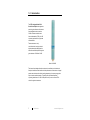
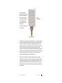
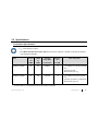
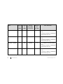
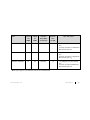
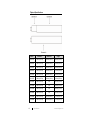
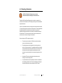
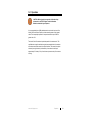
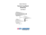
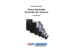
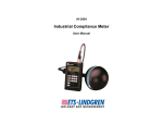
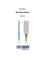
Model 3126 Series Sleeve Dipole Antenna User Manual Model 3126-2450 Model 3126-3600 ETS-Lindgren Inc. reserves the right to make changes to any products herein to improve functioning or design. Although the information in this document has been carefully reviewed and is believed to be reliable, ETS-Lindgren does not assume any liability arising out of the application or use of any product or circuit described herein; nor does it convey any license under its patent rights nor the rights of others. All trademarks are the property of their respective owners. © Copyright 2004–2014 by ETS-Lindgren Inc. All Rights Reserved. No part of this document may be copied by any means without written permission from ETS-Lindgren Inc. Trademarks used in this document: The ETS-Lindgren logo is a registered trademark of ETS-Lindgren Inc; Teflon is a registered trademark of E. I. du Pont de Nemours and Company or its affiliates. Revision Record MANUAL,3126 | Part # 399155, Rev. D ii Revision Description Date A Initial Release January, 2004 B Addition of new model data March, 2006 C Updated Specifications; rebrand November, 2010 D Minor corrections/edits October, 2014 www.ets-lindgren.com Table of Contents Notes, Cautions, and Warnings ................................................ v 1.0 Introduction .......................................................................... 7 Standard Configuration ............................................................................... 9 Optional Items ............................................................................................ 9 CTIA Ripple Test Mounting Kit ............................................................ 9 Model 3127 Resonant Loop Antenna .................................................. 9 ETS-Lindgren Product Information Bulletin ............................................... 10 2.0 Maintenance ....................................................................... 11 Service Procedures .................................................................................. 12 Contacting ETS-Lindgren .................................................................. 12 Sending a Component for Service..................................................... 12 Calibration Services and Annual Calibration...................................... 12 3.0 Specifications ..................................................................... 13 Performance Specifications ...................................................................... 13 Physical Specifications ............................................................................. 16 4.0 Mounting Information ........................................................ 17 5.0 Operation ............................................................................ 19 Appendix A: Warranty ............................................................. 21 Duration of Warranties .............................................................................. 21 www.ets-lindgren.com iii This page intentionally left blank. iv www.ets-lindgren.com Notes, Cautions, and Warnings Note: Denotes helpful information intended to provide tips for better use of the product. Caution: Denotes a hazard. Failure to follow instructions could result in minor personal injury and/or property damage. Included text gives proper procedures. Warning: Denotes a hazard. Failure to follow instructions could result in SEVERE personal injury and/or property damage. Included text gives proper procedures. Note: See the ETS-Lindgren Product Information Bulletin for safety, regulatory, and other product marking information. www.ets-lindgren.com v This page intentionally left blank. vi www.ets-lindgren.com 1.0 Introduction The ETS-Lindgren Model 3126 Series Sleeve Dipole is designed as precision gain references for antenna range calibration and to meet the Cellular Telecommunication and Internet Association (CTIA) ±0.1 dB symmetry requirement for ripple test measurements. These antennas are truly omni-directional, having an electric dipole pattern approaching that of a half-wave resonant dipole with typical gains between 1.5 dB and 2.0 dB. Model 3126-2450 The sleeve dipole design allows the antenna to be end-fed to avoid cable and feed-point interactions that interfere with the performance of the antenna. Integral quarter-wave chokes and/or ferrite loading (depending on frequency range) also helps to reduce cable interaction. This design also provides exceptional symmetry (better than ±0.1 dB, 0.2 dB peak-to-null) to meet or exceed CTIA criteria for ripple test antennas. 7 Introduction www.ets-lindgren.com The higher-frequency antennas include a radome, and are characterized with the radome in place. The radome provides improved dielectric properties for superior high frequency performance. Do not remove the radome for any reason. Model 3126-3600 Each Model 3126 is designed with a VSWR less than 1.2:1 in at least a ±10 MHz band around the labeled center frequency. Gain values and ±0.1 dB symmetry certification are provided for a 200 MHz to 300 MHz band (depending on the specific model) centered about the labeled frequency. The dipoles have a typical VSWR <3:1 across this entire band, and may be used for precision range calibrations across the entire band provided appropriate padding (recommended 10 dB) is used to minimize possible standing wave effects on cables. The dipoles have nominal impedance of 50 Ω, a maximum continuous transmit power of one watt, and are equipped with a female SMA connector. The dipoles are calibrated using an A2LA accredited process with a typical measurement uncertainty on the order of ±0.2 dB. During the calibration process, the dipoles are also certified to meet the ±0.1 dB symmetry required for use in the ripple test specified in the CTIA Over-The-Air Performance Test Plan. Gain, VSWR, maximum ripple, and measurement uncertainty values are provided with each calibration. www.ets-lindgren.com Introduction 8 Standard Configuration Note: All Model 3126 dipole antennas are not listed in this manual; contact ETS-Lindgren Sales for a list of available Model 3126 dipole antennas. Model 3126 Sleeve Dipole Antenna A2LA accredited precision calibration and symmetry certification including signed Certificate of Calibration Optional Items Note: Contact ETS-Lindgren Sales for information on ordering optional items. CTIA RIPPLE TEST MOUNTING KIT This optional ripple test mounting kit is available to attach the dipole to an ETS-Lindgren Multi-Axis Positioning System (MAPS™). The mounting kit provides the adapters necessary to position dipole and loop antennas at each offset geometry required to perform the ripple test, as specified in the CTIA test plan. The center position mount can also be used for performing range calibrations (CTIA Substitution Part) and is the same mount design used for calibrating the antenna, thereby reducing measurement uncertainty. MODEL 3127 RESONANT LOOP ANTENNA Magnetic dipole antennas designed to meet the CTIA +\-0.1 dB symmetry requirement for ripple test measurements at the labeled center frequency. 9 Introduction www.ets-lindgren.com ETS-Lindgren Product Information Bulletin See the ETS-Lindgren Product Information Bulletin included with your shipment for the following: Warranty information Safety, regulatory, and other product marking information Steps to receive your shipment Steps to return a component for service ETS-Lindgren calibration service ETS-Lindgren contact information www.ets-lindgren.com Introduction 10 2.0 Maintenance CAUTION: Before performing any maintenance, follow the safety information in the ETS-Lindgren Product Information Bulletin included with your shipment. WARNING: Maintenance of the Model 3126 is limited to external components such as cables or connectors. If the Model 3126 requires cleaning, use a clean soft cloth moistened with water. Do not use any harsh or abrasive chemicals; they may damage the components. WARRANTY If you have any questions concerning maintenance, contact ETS-Lindgren Customer Service. Note: ETS-Lindgren may substitute a similar part or new part number with the same functionality for another part/part number. Contact ETS-Lindgren for questions about part numbers and ordering parts. 11 Maintenance www.ets-lindgren.com Service Procedures CONTACTING ETS-LINDGREN Note: Please see www.ets-lindgren.com for a list of ETS-Lindgren offices, including phone and email contact information. SENDING A COMPONENT FOR SERVICE For the steps to return a system or system component to ETS-Lindgren for service, see the Product Information Bulletin included with your shipment. CALIBRATION SERVICES AND ANNUAL CALIBRATION See the Product Information Bulletin included with your shipment for information on ETS-Lindgren calibration services. www.ets-lindgren.com Maintenance 12 3.0 Specifications Performance Specifications f0 = center frequency of dipole For a Model 3126-2450 Sleeve Dipole Antenna: A 20% band is 2450*0.20 = 490 MHz, so the dipole is calibrated from 2205 MHz to 2695 MHz. Band % Band % Band 1.2:1 2:1 Calibration Range (MHz) Minimum Gain VSWR VSWR Centered at f0 at f0 (dB) 400 MHz—600 MHz 1.5% 10% 600 MHz—836 MHz 2% 15% * 200 MHz 200 MHz Pass / Fail Criteria 1.5 1.2:1 VSWR on a 1.5% band centered at f0 Symmetry <0.2 dB Meet minimum gain at f0 1.5 1.2:1 VSWR on a 2% band centered at f0 Symmetry <0.2 dB for 2:1 VSWR band Meet minimum gain at f0 * The lower frequency of the calibration band cannot be less than 400 MHz. www.ets-lindgren.com Specifications 13 Band 14 2:1 Calibration Range (MHz) Minimum Gain VSWR VSWR Centered at f0 at f0 (dB) 836MHz—1000MHz 2.5% 15% 200 MHz 1.5 1.2:1 VSWR on a 2.5% band centered at f0 Symmetry <0.2 dB for 2:1 VSWR band Meet minimum gain at f0 1000MHz—1800MHz 3% 15% 300 MHz 1.5 1.2:1 VSWR on a 3% band centered at f0 Symmetry <0.2 dB for 2:1 VSWR band Meet minimum gain at f0 1800 MHz—1920 MHz 3% 15% 300 MHz 1.5 1.2:1 VSWR on a 3% band centered at f0 Symmetry <0.2 dB for 2:1 VSWR band Meet minimum gain at f0 1920 MHz—2150 MHz 4% 15% 20% of band 1.5 1.2:1 VSWR on a 4% band centered at f0 Symmetry <0. 2dB for 2:1 VSWR band Meet minimum gain at f0 Specifications % Band % Band 1.2:1 Pass / Fail Criteria www.ets-lindgren.com Band % Band % Band 2:1 Calibration Range (MHz) Minimum Gain 1.2:1 VSWR VSWR Centered at f0 at f0 (dB) 2150 MHz—2840 MHz 4% 15% 20% of band 1.5 1.2:1 VSWR on a 4% band centered at f0 Symmetry <0.2 dB for 2:1 VSWR band Meet minimum gain at f0 2840 MHz—4500 MHz 2% 10% 500 MHz 1.4 1.2:1 VSWR on a 2% band centered at f0 Symmetry <0.2 dB for 2:1 VSWR band Meet minimum gain at f0 4500 MHz—6000 MHz 3% 15% 1000 MHz 1.0 1.2:1 VSWR on a 3% band centered at f0 Symmetry <0.2 dB for 200 MHz band Meet minimum gain at f0 # Pass / Fail Criteria # The upper frequency of the calibration band cannot exceed 6000 MHz. www.ets-lindgren.com Specifications 15 Physical Specifications 16 Model Diameter A Diameter B Length 3126–700 1.90 cm (0.75 in) 2.69 cm (1.06 in) 39.4 cm (15.5 in) 3126–836 1.90 cm (0.75 in) 2.69 cm (1.06 in) 24.46 cm (9.63 in) 3126–880 1.90 cm (0.75 in) 2.69 cm (1.06 in) 24.46 cm (9.63 in) 3126–920 1.90 cm (0.75 in) 2.69 cm (1.06 in) 24.13 cm (9.50 in) 3126–1225 1.90 cm (0.75 in) 2.69 cm (1.06 in) 22.86 cm (9.00 in) 3126–1575 1.90 cm (0.75 in) 2.69 cm (1.06 in) 21.59 cm (8.50 in) 3126–1845 1.90 cm (0.75 in) NA 19.51 cm (7.68 in) 3126–1880 1.90 cm (0.75 in) NA 19.30 cm (7.60 in) 3126–2140 1.90 cm (0.75 in) NA 19.05 cm (7.50 in) 3126–2450 1.90 cm (0.75 in) NA 18.75 cm (7.38 in) 3126-3600 1.90 cm (0.75 in) 7.62 cm (3.00 in) 21.11 cm (8.31 in) 3126-5500 1.90 cm (0.75 in) 7.62 cm (3.00 in) 21.11 cm (8.31 in) Specifications www.ets-lindgren.com 4.0 Mounting Information CAUTION: The Model 3126 antennas are precision measurement devices. Handle your antenna with care. The Model 3126 Series Sleeve Dipole must be mounted to a support at the connector end of the antenna. An ETS-Lindgren mounting kit is recommended to support the antenna. Under no circumstances should any mounting structure extend inward more than 1.5 inches (38 mm) past the connector end of the antenna. This area approaches the radiating element of the antenna and any material in this region will significantly change the performance of the antenna and affect the accuracy of the measurement. The mounting structure should have a low dielectric and a minimum amount of mass in the region of the antenna. When mounting to an ETS-Lindgren mounting kit: The antenna mount consists of a Teflon® sleeve with small clamp screws to hold the antenna in place. Fixed length spacers are then attached to the mounting sleeve to position it at each test position. For repeatable positioning, the antenna must be inserted into the sleeve until it bottoms out in the socket, then the clamp screws should be tightened symmetrically around the antenna to ensure that the axis of the antenna is along the axis of the mount. Note that an RF cable must be attached to the antenna prior to inserting it into the mounting socket. An optional blind mate socket and adaptor combination is available to allow attaching the cable to the Teflon socket adapter and sliding the antenna with blind mate connector adaptor into the RF socket. www.ets-lindgren.com Mounting Information 17 Ferrite loaded RF cables are recommended for use with the Model 3126 to minimize the interaction with the dipole. ETS-Lindgren offers a line of ferrite loaded cables for this application. Lightweight RF cabling should be used and properly supported to avoid putting unnecessary load on the SMA connector of the antenna. Route cabling away from the antenna along the antenna axis for as far away as is practical to minimize the interaction of the cable with the antenna and to avoid distortion of the antenna pattern. 18 Mounting Information www.ets-lindgren.com 5.0 Operation CAUTION: Before placing into operation, follow the safety information in the ETS-Lindgren Product Information Bulletin included with your shipment. It is recommended that a 10 dB pad/attenuator be used at the input end of the Model 3126 Series Sleeve Dipole to minimize standing waves on the transmit cable. This is especially important for frequencies where the input VSWR is greater than 1.2:1. The electric field of the antenna is polarized parallel to the antenna axis. The specified antenna gain is realized along the plane perpendicular to the antenna axis and centered at the center of the dipole elements. The center of the dipole elements (bore sight location) is indicated by a line marked on the dipole, approximately 5.9 inches (15 cm) from the base (connector end) of the antenna housing. www.ets-lindgren.com Operation 19 This page intentionally left blank. 20 Operation www.ets-lindgren.com Appendix A: Warranty Note: See the Product Information Bulletin included with your shipment for the complete ETS-Lindgren warranty for your Model 3126. Duration of Warranties All product warranties, except the warranty of title, and all remedies for warranty failures are limited to two years. Product Warranted Duration of Warranty Period Model 3126 Series Sleeve Dipole 2 Years www.ets-lindgren.com Warranty 21