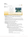
1
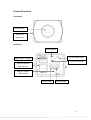
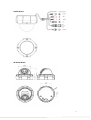
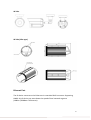
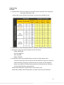
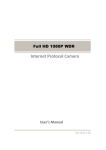
2M / HD 720P
Internet Protocol Camera
User's Manual
Ver.2011 / 07
1
Table of Contents
Copyrights & Trademarks
Reading Before Using
Warning Before Using
Package Content
Physical Description
Connect to device and setup IP
Example to setup IP of your PC (Win 7)
Recommended PC Specification
4
5
5
6
7
11
14
21
Layout
Live view
22
22
Setup Network
IP Networking
Dynamic DNS
UPnP
Bonjour
Connection Ports
IP Filter
Multicast RTP
2
24
27
28
28
29
28
31
Camera
Image Setting
Text Overlay
Video & Audio
Video
Audio
30
32
34
35
35
36
Events
Event Servers
FTP
E-Mail
38
38
39
40
Motion Setup
Alarm I/O
Alarm Definition
Schedule Definition
42
41
43
44
System
E-mail Server
Date & Time
Users
System Name
Maintenance
Logs
63
63
64
65
69
73
74
2
Copyrights & Trademarks
Copyright
© 2010
Trademarks
Microsoft and Windows are registered trademarks of Microsoft Corporation.
All other trademarks mentioned in this document are trademarks of their respective
owners.
Disclaimer
This document is intended for general information purposes only, and due care has
been taken in its preparation.
Any risk arising from the use of this information rests with the recipient, and nothing
herein should be construed as constituting any kind of warranty.
The distributor reserves the right to make adjustments without prior notification.
All names of people and organizations used in these documents examples are
fictitious. Any resemblance to any actual organization or person, living or dead, is
purely coincidental and unintended.
3
Reading Before Using
You should read all the safety and operating instructions before using this product.
The use of surveillance devices may be prohibited by law in your country. The IP
Camera is not only a high-performance web-ready camera, but can also be part of a
flexible surveillance system. It is the user’s responsibility to ensure that the operation
of such devices is legal before installing this unit for its intended use.
Warning Before Using
1. Abnormal: Power off the IP Camera immediately when the smoke or unusual
odors are detected.
2. Voltage: Don not use the power supply with other voltages, if you use a power
supply with different voltage than the one included with this device. It is likely to
be damaged or damage other equipments / personnel.
3. Humidity: Keep the IP Camera dry inside. If it becomes wet, power off is
necessary! Do not place it in high humidity environments.
4. Temperature: Refer to your user’s manual for the operating temperature; do not
place around heat sources, direct sunlight.
5. Disassemble: Do not open the housing of this IP Camera; avoid disassembling
and inserting the sharp or tiny things.
6. Accessory: Do not use attachment / accessory not recommend by Raylios.
All warranty will be voided in the situations above.
4
Package Content
Box Cam
*Lens not included
Vandal Dome
IR Vandal Dome (35 IR LED)
IR Vandal Dome (50 IR LED)
*accessory package is included
IR Tube
IR Tube (Slim type)
*accessory package is included
Power Adaptor
Software CD
Product CD in the package contains the following:
Search Tool
CMS M1-064Operation Manual
5
Physical Description
Front Panel
Lens & Sensor
Back Focus
Adjustment
Back Panel
Reset Button
DC 12V Power Input
Digital Input / Output
Power Status LED
Ethernet 10/100
RJ45 Connect
Auto-Iris Control
Cable Socket
Audio Input
Audio output
6
Vandal Dome
IR Vandal Dome
7
IR Tube
IR Tube (Slim type)
Ethernet Port
The IP device connects to the Ethernet via a standard RJ45 connector. Supporting
NWAY, this IP device can auto detect the speed of local network segment
(10Base-T/100Base-TX Ethernet).
8
Reset Button
Step 1: Switch off IP device by disconnecting the power cable
Step 2: Press and continue to hold the Reset Button (with a sharp tipped object, like a
pen.)
Step 3: Reconnect the power cable while continuing to hold the reset button. The
Power LED light will turn orange for about 15 seconds, and then turn green for about
5 seconds. By this time the reset to default operation is already completed. This reset
operation time fluctuates slightly with the environment.
Audio Input / Output
The IP device supports audio input and output with earphone jack.
Digital Input / Output
Used in applications like motion detection, event triggering, time lapse recording,
alarm notifications, etc., the I/O terminal connector provides the interface to:
1. Transistor output – for connecting external devices such as relays and LEDs.
Connected devices can be activated by Output buttons on the Live View page or
through video management software.
2. Digital Input – An alarm input for connecting devices that can toggle between an
open and closed circuit, for example: PIRs, door/window contacts, glass break
detectors, etc. The device will detect the change in digital input and transmit the
signal to video surveillance servers.
9
Connect to device and setup IP
This section describes how to configure the IP device. The administrator has
unlimited access to all settings, while the normal user can only view live video. The IP
device is configured under a standard browser (Microsoft Internet Explorer 6.0 or
above).
If you have DHCP server / router in your network:
If you are using a network server / router which are able to automatically provide IP
addresses through DHCP, just plug in your computer and IP Box Camera into the
device and it will acquire network address by itself. Find and access the device with
our “Skate” (IP Device Search Tool), which is in our package CD with the camera.
If you do NOT have DHCP server / router in your network:
Please assign a static IP for each device and add them one by one. Connect to the
first device by following steps 1 to 9 below.
Before adding more devices into the network, you need to change the current device
to a new IP address so no two devices have IP conflict. (Steps 6 to 9).
10
For adding devices without DHCP, please see following steps.
1. Connect the PC to the Network Switch with the CAT5 cable, and change your PC’s
IP to 192.168.1.99 / Subnet Mask 255.255.255.0 (99 is just a sample, it may be
any number from 1 to 254 except 50.)
2. Connect the device to your Network Switch. If it is a PoE enabled Switch, then the
device is powered on. If it is NOT a PoE enabled Switch, please also plug in the
Power Adapter.
3. Open Internet Explorer (Version 6.0 or above), and type in
Default IP: http://192.168.1.50
4. When you see the login window, please input default user and password:
Default User name: Admin
Password: password
5. After you log in, you will see the video from IP device. To go to the main menu,
click the “Setup” button on the top right.
6. Please go to Network IP Networking. Change the IP mode to Static IP and the IP
address to 192.168.1.101 or any other unused IP (Avoid 192.168.1.50, the IP of
your PCs and other devices already in network.). Click “Apply” then click System
Maintenance Reboot this device
7. Internet Explorer will reopen after a few seconds. This is normal.
8. Wait for 40 seconds and reopen IE by typing in the new IP. (in this example,
192.168.1.101). For later device you add into the network, please choose an IP
that is not used by any existing device.
9. If you have more than one device, continue again from step 2. Assign different
new IP to each camera (for instance 192.168.1.102) You do not need to unplug
the existing devices from the witch because there is no IP conflict.
11
Login
1. Open Internet Explorer 6.0 or above. You may download the latest version from:
http://www.microsoft.com/windows/ie/downloads/default.mspx
2. Enter the IP address of the IP device and press enter to go to Login Page. The
default IP address is “http://192.168.1.161/”
3. Enter the Account name and the Password
(Default Account: Admin/Password: password)
4. Click “OK” or click “Cancel” to re-enter again.
12
Example to setup IP of your PC (Win 7)
The procedures are as below show how to setup your IP on Windows XP. If you use
operating system other than Windows XP, please refer to OS manuals for proper
setup procedures.
1. Start up your PC.
2. Click the [Start] and select the “Control Panel”
13
Double check the “Network and internet connection” icon
1. Double check the “Network Connection” icon
14
2. Click “Change adapter settings” in the Network Task menu.
3. Click “Lacal Area Connection” Click Right
15
4. Click “Internet Protocol (TCP/IP)”, and then click [Properties]
5. Click the “Use the following IP address” radio button and enter IP address and the
subnet mask.
Please set the settings as below.
IP address: 192.168.1.xxx
Subnet mask: 255.255.255.0
(NOTE: xxx should be a number from
1 to 254 except 50, which is used by
the IP device. Please also make sure
that no two equipments use the
same IP address in the same
network.)
Click the [OK] button and the window dialog box will close.
16
Set ActivX
1. Toolbar→Tools→Internet Options
17
2. Security→Click the Custom Level…
18
3.
“Download signed ActiveX controls” and” Download unsigned ActiveX controls”,
Click the “ Prompt”
4. Click the “ Alppy”
19
Recommended PC Specification
CPU
Core2Duo 2.13GHz and above
Memory
2GB or above
Operating System
Windows XP with SP2 or above. Windows Vista / Windows 2003 / Windows 7
Internet Explorer 6.0 SP2 and above.
Video Resolution
SVGA or XGA with 1024x768 resolution
Kindly refer to the Solution Commander to choose the suitable PC Specification:
http://www.raylios.com/calculators.asp?ID=36&ChannelID=104&lang=en
20
Layout
Live view
This chapter explains the layout of the Live View page. It is composed of the
following sections:
1. Click the [Live View] tab to show [Live View page].
2. IF you want to setup this IP camera/video server, please click the [Setup]
tab to switch to “Setup Page”
3.
Full Screen:
Click the icon to stretch the preview to full screen. You can click “Esc” button
on the keyboard to return to previous display.
4. Snapshot:
Click the icon to take a snapshot. The snapshot picture will be saved to the
default folder “C:\Users\Account Name\Documents\ArkViewer\pic”, in the
format of YYYYMMDD_HH-mm-ss.jpg.
21
5. Manual Recording:
Click the icon to do the manual recording. The recording video file will be
saved to
the default folder “C:\Users\Account Name\Documents\ArkViewer\avi”, in the
format of YYYYMMDD_HH-mm-ss.avi.
6. Audio out:
Click the icon to enable the audio out from PC to IP camera or video server.
When it is enabled, your voice will be transferred to the audio out of the IP
camera.
Note: You will need to have a microphone connected to your PC.
7. Audio in:
Click the icon to mute or the icon to receive audio in from the IP camera. Drag
the volume bar to adjust the volume.
8. Stream Codec:
Click to select the compression codec used in video. The codec type option
includes H.264, MPEG4 and MJPEG. Once selected, the IP camera will start to
send video in new stream type.
9. Language:
Click to select the language of user interface. English / Traditional Chinese
22
Setup
This chapter explains how to select the stream transmission mode and saving options
of firmware in IP Cameras. When completed with the setting on this page, click
“Apply” on the page bottom to enable the settings.
Network
IP Networking
1. Click the [Setup] tab to show [Setup page].
2. Click the [Network] tab to show [Network page]
3. Click the[IP Networking] tab to show [IP Networking page]
Connection Type: select the DHCP Client / Static IP / PPPoE
23
DHCP Client
Choose the Connection Type as [DHCP Client]
Click “Apply” to confirm the DHCP function.
Static IP
Choose the Connection Type as [Static IP]
24
1.
IP Address: you can setup the IP address of this IP camera, kindly refer to
2.
3.
the Connect to device and setup IP for more detail setting.
Subnet Mask: should be 255.255.255.0
Gateway:192.168.1.1
4.
5.
DNS1:168.95.1.1
DN2: 168.95.192.1
PPPoE
Choose the Connection Type as [PPPoE]
PPPoE requires an account provided by your ISP
Edit the User Name and Password, and then confirm the password. Click “Apply”
to confirm the Edition and PPPoE function.
25
Dynamic DNS
DDNS configuration >> change to DDNS function enable page.
Click the [Dynamic DNS] item to show the [Dynamic DNS setting page]
DDNS is a service that allows your IP Camera, especially when assigned with a
Dynamic IP address, to have a fixed host and domain name.
1. DDNS Service: click the check point to enable or disable the DDNS Service
function.
Refer to the following links to apply for a dynamic domain account when selecting
other DDNS providers:
Dyndns.org (Dynamic) / Dyndns.org (Custom): www.dyndns.com
26
UPnP
Click the [UPnP] item to display the [UPnP setting page]
1. Enable UPnP: click the checkbox to enable or disable the UPnP function.
2. Device name: Edit the device name in text field.
Bonjour
Click the [Bonjour] item to display the [Bonjour setting page]
Bonjour let IP Camera work with MAC (Apple) Operation System.
1. Enable Bonjour: click the checkbox to enable or disable the Bonjour function.
2. Service name: Edit the device name in the text field.
27
Connection Ports
Click the [Connection Ports] item to display the [Connection Ports setting page]
1. Setup the HTTP port: default setting will be 80, after setup, click “Apply”
2. Setup the RTSP port: default setting will be 554, after setup, click “Apply”
Can be assigned to another port number between 1025 and 65535.
28
IP Filter
Click the [IP Filter] item to display the [IP Filter page].
Only those clients whose IP address is on the Allowed list and not on the Reject List
can access the IP camera.
1. Enable IP Filter: Click the checkbox to enable or disable the IP Filter function.
2. Rule: Accept / Reject the IP Address listed in the below.
3. Set IP: Key in IP Address.
4. After setup, Click “Apply”
29
Multicast RTP
Click [Multicast RTP] to show the [Multicast RTP page]
Multicast sends a stream to the multicast group address and allows multiple clients
to acquire the stream at the same time by requesting a company from the multicast
group address. Enable multicast can effectively save Internet bandwidth.
1. Address: Select the multicast IP address. Default settings is 239.243.251.26
2. Time to live: Set up the number of time to live.
30
Camera
Image Setting
Image Setting: Image Setting Page. This tab concerns the general video settings.
1. Brightness: Select the value. The higher this value, the brighter view.
2. Saturation: Select the value. The higher this value, the more colorful view.
Too colorful might be unnatural.
3. Contrast: Select the value. The higher this value, there are more level between
Black & White, make the detail clearer. Noise might be clearer at the same time
4. Sharpness: Select the Sharpness value. The higher this value, the shape of item is
clearer. Noise might be clearer at the same time.
5. Exposure: Select the Exposure mode for 60Htz or 50Htz.
6. Manual Shutter: Select the Shutter mode for
7. White Balance: Select the White Balance mode for
a. Auto: the IP Camera automatically adjusts the color of the light in
response to different lighting condition. The white balance setting
defaults to Auto and works well in most situations.
b. Manual: Adjust the value of R-gain / B-gain to get the best color.
c. Hold Current: follow the steps below to manually set the white balance
to compensate for the ambient lighting conditions:
Firstly: Set the white balance to auto and click “Apply”
Secondly: Place a sheet of white paper in front of the lens, and
then allow the IP Camera to adjust the color automatically.
Thirdly: Select Hold Current to confirm the setting while the color
is being measured.
Finally: Click “Apply” to enable the current setting
31
8. R-gain: the higher this value, the color is closer to red (warm color)
9. B-gain: the higher this value, the color is closer to blue (cold color)
10. Day/Night: Select the mode for Auto / On / Off of night mode (Black and White)
11. Day Threshold: Select the Threshold value. The higher this value, the easier turn
to night mode.
12. AGC: Select the AGC value. The higher this value, the larger each signal, included
brightness, and noise.
13. Rotation: Click to enable or disable “Flip” & “Mirror”
14. Auto Iris: Click to enable or disable “Enable”
You can see the preview to fine-tune the image, or click restore to recall the original
settings without incorporating the changes. When completed with the settings on
this page, click “Apply” to enable the setting.
32
Text Overlay
Click the [Text Overlay] item to display the [Text Overlay Page].
1. Include date: Click the checkbox to enable or disable the date of text overlay.
2. Include time: Click the checkbox to enable or disable the time of text overlay.
3. Include text: Click the checkbox to enable or disable the text which you edit in
the column.
4. Product serial number
5. After setup, click “Apply”
33
Video & Audio
Video
Click the [Video] item to display the [Video Page]. The functions here are
34
Image Setting
H.264:
a. Fixed Bit Rate: select the Video bit rate value remains constant at all conditions
From Max: 6M to Min: 28k
Kindly refer to the Solution Commander to choose the suitable Bit rate:
b. Fixed Quality: select the Quality value for Standard / Good / Great / Excellent
c. Resolution: Select the video resolution of the IP Camera
UXGA: 1600x1200
HD 720: 1280x720
VGA: 640x480
QVGA: 320x240
d. Frame Rate: Select the available frame rate from the drop down menu.
This puts a hard cap on the maximum bit rate allowed in any given second of
video streaming. Assigning a limited bit rate may result in a few dropped
frames rate when the stream data overflows the allowed bit rate. Doing so
will also disable Bit Rate setting below.
Under UXGA Resolution, the Max Frame rate will be 15 fps
Under VGA / QVGA / HD 720 Resolution, the Max Frame rate will be 30 fps
35
MPEG4: Same concept as H.264
JPEG: Same concept as H.264
Audio
Click the [Audio] item to display the [Audio Page].
1. Enable Audio: click the checkbox to enable or disable the Audio recording
function by Audio in.
2. Encoder type: Select the encoder type by G.726 / G.711 µ-law
3. Bit rate: Set up the bit rate by 16 / 32 Kbps of Audio Stream.
36
Events
Click the [Events] item to display the [Events Page].
Event Servers
Click the [Event Servers] item to display the [Event Servers Page].
Click [Add] to Open the setup page.
Server Type: select the FTP/E-Mail/HTTP/TCP
37
Example Operation
FTP
Name: Edit the name of the server
Address: Edit the address of the server
Port: Edit the Port of the server
Passive Mode:
User: username
Password: password
Remote Folder:
Click “Apply” to confirm the setting.
38
E-Mail
Name: Enter the user name (Not with the FTP / HTTP / TCP to set the same user
name)
Recipient: Enter the recipient,Click the “ + “( Can set up multiple)
Click “Apply” to confirm the setting.
39
HTTP
If the user has installed HTTP Server, sequence input settings.
Click “Apply” to confirm the setting.
TCP
Enter Name (Not with the FTP/ HTTP/TCP to set the same user name)、Address、Port
Click “Apply” to confirm the setting.
40
Motion Setup
Click the [Motion Setup] item to display the [Motion Setup Page].
Separate into 3 Region of Motion Detection.
1. Click
to add a new motion detection window.
Once it is added, there will be a motion window shows in the live view screen.
You can adjust column and Square, to set up the region as you want.
2. Click
to cancel an exist motion detection window.
3. Window Name: Setup the name of motion window.
4. Enable: Click to enable or disable each motion window.
5. Sensitivity: Set the sensitivity of motion detection region, the higher this value,
the easier camera considers video change to be an activity.
6. Threshold: Set the threshold of motion detection region, the larger this value, the
larger the object size and activity needed to trigger motion detection.
41
Alarm I/O
Click the [Alarm I/O] item to display the [Alarm I/O Page]
1. Port: Separate in to Digital Input / Output.
2. Name: Edit the name of Digital Input / Output.
3. Normal Status: Setup the normal status of Digital Input / Output.
4. Current Status: See the current status of Digital Input / Output.
42
Alarm Definition
Click the [Alarm Definition] item to display the [Alarm Definition Page].
Click [Add] to Open the setup page.
43
1. Name: Event Name
2. Alarm:
a. Trigger Interval: Action time
b. Working Time: select the Disable/Always/Manual
c. Trigger by:
Motion Detection
Input Port
System Starting
d. Condition:
Starting
Stopped
Start -> Stop
44
3. Action:
Activate output port
Send E-Mail notification
Send HTTP notification
Send TCP notification
Upload images via FTP
Upload images via E-Mail
45
Schedule Definition
Click the [Schedule Definition] item to display the [Schedule Definition Page].
Methods of operation with the Upload images via Alarm Definition
46
Example Operation
1. When the door is opened, alarm is triggered.
Alarm
Name: Event Name(For example in Figure: Triggering alarm, the door is opened,
So Named for the door)
Working Time:
select Manual, Click the Edit
47
Into the edit page
48
Example: Monday -Friday 8:00 am No one will enter the company , prevent
malicious intrusion, setting time for Monday -Friday 8:00 am , then Click the [Add>>]
(Can set up multiple)
Click “Apply” to confirm the setting.
49
Action
select the [Activate output port]
After the action,after a few seconds delay to start recording
click the check point to enable and set the last upload for a few seconds
click the check point to enable the “Kepp activating during this event”Service
function.
Click “Apply” to confirm the setting.
50
Click “Apply” to confirm the setting.
51
select the [Send E-Mail notification]
E-mail template: [Events]->[Event Servers] Set new E-Mail, select the [mail]
Subject key in “door open”
Content key in “door open”
Click “Apply”
52
Click “Apply” to confirm the setting.
53
select the [Send HTTP notification]
HTTP sever: select the [HTTP]
Massage: key in “door open”
54
Click “Apply” to confirm the setting.
55
select the [Send TCP notification]
TCP sever: select the [TCP]
Massage: key in “door open”
56
Click “Apply” to confirm the setting.
57
select the [Upload images via FTP]
1. FTP server: [Events]->[Event Servers]Set new FTP, select the[admin]
2. For example in Figure: Open the front door (Pre alarm) 60 seconds 30 frames per
58
second.
3. The door is opened (Post alarm) 60 seconds 30 frames per second.
4. Include live images
Keep uploading for_second: The time taken to set their own image
Keep uploading till end of event
Options on the Figure,that screen time is saved action until one minute before the
action began after the end ofone minute
Click “Apply” to confirm the setting.
59
select the [Upload images via E-Mail]
Methods of operation with the Upload images via FTP
60
Click “Apply” to confirm the setting.
61
System
This section explains how to configure the basic settings for the IP Cameras, such as
the host name and system time.
Click the [System] item to display the [System Page].
E-mail Server
Click the [E-mail Server] item to display the [E-mail Server Page].
SMTP Sever: For example Gmail’s SMTP Sever for smtp.gmail.com
Port: Default Port:25
Sender
Authentication: select the off/PLAIN/LOGIN
User Name
Password
62
Date & Time
Click the [Data & Time] item to see [Date & Time Setting Page].
The default method is Sync with time server.
Method: select the Sync with time server/Manual/Sync with PC
63
Method: select the [Sync with time server]
Method: select the [Manual]
Manual inputDate and Time
64
Method: select the [Sync with PC]
65
Users
You can set up different roles of Viewers, Operators & Administrators.
Administrator account allows the user to watch the live view and setup everything;
but viewers account allows user only to watch the live image.
Viewers: Browse only (No permission)
Operators: Some functions can be modified
Adminstrators: Administrators (Maximum permissions)
66
Example Operation
Permissions you want to add content on the right point (above) -> [Add a new
viewer]
67
Enter user name and password
68
Complete
69
System Name
Can change the Tittle name/Host name/ Domain name
Example Operation
70
Change Tittle name
Complete
71
Maintenance
Click the [Maintenance] to enter [Maintenance Page].
1. Restore to factory default: If you want to reset all the settings. You will have to
use factory default IP setting to connect to this camera. Please refer to previous
login section.
2. Reboot this device: If you want to save all the settings and reboot this IP camera.
Some settings might not take effect before save and reboot.
After around 40 seconds, the IP Camera will reopen the setting page to indicate
the reboot is finished.
3. Firmware Upgrade:
a. Select File: select the upgrade file. You can always get the latest version
at our website.
4. Upload Logo/Restore Logo
72
Logs
Click the [Logs] to enter [Logs Page].
Click [Refresh]
73
Log Level: select the
INFO/WARNING/ERROR/FATAL/ALL
74