1
CNA-100 Automation
TM
Setup and Operation Manual
Revision 2.00
March 2005
CNA 100 Automation
Setup and Operation Manual
PR004
Revision 2
This manual covers the setup and operation of CNA-100 automation system.
Optional CineNet and related equipment is covered in the following product reference manuals:
!
!
!
!
!
!
!
!
!
!
!
!
!
!
!
!
!
!
!
PR001 CNA Installation Manual
PR002 CNA-200 Setup and Operation Manual
PR003 CNA-150 Setup and Operation Manual
PR004 CNA-100 Setup and Operation Manual
PR005 QDC-400 Installation and Setup Manual
PR006 ACP-50 Installation and Setup Manual
PR007 RVC-5 Installation and Setup Manual
PR008 PCI-64 Gateway Interface Installation
PR009 CineNet Host Software
PR010 RCM-10/RSM-10/RSM-20 Installation and Operation Manual
PR011 Strong Dimmer Installation, Setup, and Operation Manual
PR012 eCNA-100 Automation Manual
PR013 eCNA-150 Automation Manual
PR014 eCNA-200 Automation Manual
PR016 Strong FP350 Installation and Operation Manual
PR017 Eprad FP350 Installation and Operation Manual
PR018 Paging system Setup and Installation Manual
PR019 VNC Setup and Operation Manual
PR020 CineSuite Installation and Operation Manual
Warranty
CineNet automation products, sold by STRONG INTERNATIONAL, are warranted against defects in materials and
workmanship for one year from the date of purchase. There are no other express or implied warranties and no
warranty of merchantability or fitness for a particular purpose.
During the warranty period, STRONG INTERNATIONAL will repair or, at its option, replace components that
prove to be defective, provided the unit is shipped prepaid to the manufacturer directly or via and authorized
distributor. Not covered by this warranty are defects caused by modification, misuse or accidents and any further
damage caused by inadequate packing for service return.
STRONG INTERNATIONAL's obligation is restricted to the repair or replacement of defective parts and under no
circumstances will STRONG INTERNATIONAL be liable for any other damage, either direct or consequential.
Information in this document is subject to change without notice. No part of this document may be reproduced or
transmitted in any form or by any means, electronic or mechanical, for any purpose, without the express written
permission of STRONG INTERNATIONAL.
© 1997 - 2005 STRONG INTERNATIONAL. All rights reserved.
Table of Contents:
Introduction . . . . . . . . . . . . . . . . . . . . . . . . . . . . . . . . . . . . . . . . . . . . . . . . . . . . . . . . . . . . . . . . . 1
Section 1 . . . . . . . . . . . . . . . . . . . . . . . . . . . . . . . . . . . . . . . . . . . . . . . . . . . . . . . . . . . . . . . . . . . . 2
System Overview . . . . . . . . . . . . . . . . . . . . . . . . . . . . . . . . . . . . . . . . . . . . . . . . . . . . . . . . . . . . . 2
Product Description . . . . . . . . . . . . . . . . . . . . . . . . . . . . . . . . . . . . . . . . . . . . . . . . . . . . . . 3
Local I/O Network (LIN) . . . . . . . . . . . . . . . . . . . . . . . . . . . . . . . . . . . . . . . . . . . . 3
Local Synchronous Network (LSN) . . . . . . . . . . . . . . . . . . . . . . . . . . . . . . . . . . . 3
System Components . . . . . . . . . . . . . . . . . . . . . . . . . . . . . . . . . . . . . . . . . . . . . . . . . . . . . . 3
Control Panel (Operator Interface) . . . . . . . . . . . . . . . . . . . . . . . . . . . . . . . . . . . . 3
Console Termination Panel . . . . . . . . . . . . . . . . . . . . . . . . . . . . . . . . . . . . . . . . . . 7
Booth Termination Panel . . . . . . . . . . . . . . . . . . . . . . . . . . . . . . . . . . . . . . . . . . . . 8
Single Termination Panel . . . . . . . . . . . . . . . . . . . . . . . . . . . . . . . . . . . . . . . . . . . . 9
Section 2 . . . . . . . . . . . . . . . . . . . . . . . . . . . . . . . . . . . . . . . . . . . . . . . . . . . . . . . . . . . . . . . . . . . 10
Setup . . . . . . . . . . . . . . . . . . . . . . . . . . . . . . . . . . . . . . . . . . . . . . . . . . . . . . . . . . . . . . . . . . . . . . 10
Configuring the System . . . . . . . . . . . . . . . . . . . . . . . . . . . . . . . . . . . . . . . . . . . . . . . . . . 10
Switch Definitions . . . . . . . . . . . . . . . . . . . . . . . . . . . . . . . . . . . . . . . . . . . . . . . . 11
Alarm Loudness . . . . . . . . . . . . . . . . . . . . . . . . . . . . . . . . . . . . . . . . . . . . . . . . . . 15
Status LEDs . . . . . . . . . . . . . . . . . . . . . . . . . . . . . . . . . . . . . . . . . . . . . . . . . . . . . 15
Programming the CNA-100 . . . . . . . . . . . . . . . . . . . . . . . . . . . . . . . . . . . . . . . . . . . . . . . 16
INTERMISSION and CURTAIN CALL Keys . . . . . . . . . . . . . . . . . . . . . . . . . . 17
Operating the CNA-100 . . . . . . . . . . . . . . . . . . . . . . . . . . . . . . . . . . . . . . . . . . . . . . . . . . 19
Soft Manual Overrides . . . . . . . . . . . . . . . . . . . . . . . . . . . . . . . . . . . . . . . . . . . . . 19
Synchronous Operation . . . . . . . . . . . . . . . . . . . . . . . . . . . . . . . . . . . . . . . . . . . . 19
System Status Messages . . . . . . . . . . . . . . . . . . . . . . . . . . . . . . . . . . . . . . . . . . . . . . . . . 20
Fault Condition Messages . . . . . . . . . . . . . . . . . . . . . . . . . . . . . . . . . . . . . . . . . . 20
Memory Faults . . . . . . . . . . . . . . . . . . . . . . . . . . . . . . . . . . . . . . . . . . . . . . . . . . . 20
Run-Time Faults . . . . . . . . . . . . . . . . . . . . . . . . . . . . . . . . . . . . . . . . . . . . . . . . . 21
Sync Interlock Failsafe Fault . . . . . . . . . . . . . . . . . . . . . . . . . . . . . . . . . . . . . . . . 22
Event and Show Logs . . . . . . . . . . . . . . . . . . . . . . . . . . . . . . . . . . . . . . . . . . . . . . . . . . . 22
Power Up Messages . . . . . . . . . . . . . . . . . . . . . . . . . . . . . . . . . . . . . . . . . . . . . . . 23
Additional Software . . . . . . . . . . . . . . . . . . . . . . . . . . . . . . . . . . . . . . . . . . . . . . . . . . . . . 23
CineNet Host . . . . . . . . . . . . . . . . . . . . . . . . . . . . . . . . . . . . . . . . . . . . . . . . . . . . . . . . . . 23
CineSuite . . . . . . . . . . . . . . . . . . . . . . . . . . . . . . . . . . . . . . . . . . . . . . . . . . . . . . . . . . . . . 23
Timing Diagrams . . . . . . . . . . . . . . . . . . . . . . . . . . . . . . . . . . . . . . . . . . . . . . . . . . . . . . . . . . . 25
Addendum . . . . . . . . . . . . . . . . . . . . . . . . . . . . . . . . . . . . . . . . . . . . . . . . . . . . . . . . . . . . . . . . . 30
Software Changes . . . . . . . . . . . . . . . . . . . . . . . . . . . . . . . . . . . . . . . . . . . . . . . . . . . . . . 30
Index . . . . . . . . . . . . . . . . . . . . . . . . . . . . . . . . . . . . . . . . . . . . . . . . . . . . . . . . . . . . . . . . . . . . . . 38
List of Illustrations . . . . . . . . . . . . . . . . . . . . . . . . . . . . . . . . . . . . . . . . . . . . . . . . . . . . . . . . . . . 39
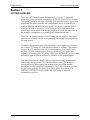
An Introduction to
CINENET™ SYSTEM
THE
Strong International’s CINENET™ is an automation and control network designed specifically for
the Motion Picture Theatre Industry. CINENET™ provides a low cost connection to various
control and I/O devices in the projection booth, auditorium, and throughout the theatre complex.
CINENET™ is divided into two network layers: The Local Synchronous Network (LSN) is a
complex-wide data network that provides advanced synchronous projector control, user selected
data transfer and real-time remote automation status. The Local I/O Network (LIN) is designed
to provide remote I/O control for each screen in a complex. The CINENET™ network offers
many advantages over point-to-point wiring such as reduced installation costs, reduced wiring
errors and high noise immunity. CINENET™ also allows management to program and access
real-time status of all auditoriums in the theatre complex from a central location using a personal
computer. Strong will continue to develop new CINENET™ products that will provide the
control and flexibility the theatre industry demands.
Strong International
1
System Overview
CNA-100 Automation Manual
Section 1
SYSTEM OVERVIEW
The CNA-100® Cinema Network Automation is a CINENET™ compatible
automation system specifically designed for the Motion Picture Theatre industry.
The system is modular in design, consisting of the operator interface and system
peripherals. The Main Computer and each peripheral device is defined by its
common functions and locations in the booth. The devices within the system
communicate with each other on a serial communications link. Automation
systems and remote stations distributed throughout the booth and other areas of
the multiplex communicate on a second serial communications link.
The CNA-100 operator interface is user friendly and self-intuitive. Once some
basic rules are learned you will be programming and running basic programs in
less than an hour.
To enhance the operation of the CNA-100 and provide a higher level of control,
the CINENET™ Gateway PC Card and Host software is available. This product
will provide a PC interface to the CNA-100 automations. The Host PC and
software will allow management to access programming, data logging and
diagnostic information from all systems connected to the network. Access to data
and system upgrade software will also be available via the modem/Internet.
This manual provides the installer and user with the necessary information to
install, setup and operate the CNA-100 automation system. The installer is
encouraged to read all sections of the manual before proceeding with the
installation. If while installing or operating the CNA-100 automation you find
any part of the manual to be unclear or incorrect, please let us know. Call
STRONG INTERNATIONAL at (800)-424-1215 if help or additional
information is required.
2
Strong International
CNA-100 Automation Manual
System Overview
Product Description
The CNA-100 Cinema Network Automation System is a microprocessor based
computer automation designed to automate all aspects of the theatre presentation.
The major features of the CNA-100 are listed below.
Local I/O Network (LIN)
Each system component is connected to the network and communicates via a five
wire cable. This cable provides the serial communications as well as power to the
termination panels. This is called the "Local I/O Network"or “LIN”. The
standard devices that make up the system are the:
1. Console Termination Panel
2. Booth Termination Panel
3. CNA-100 Control Panel
The CNA-100 Automation Control Panel contains the Main or Master Computer
of the system and each I/O device is connected to it via a serial communications
link. The devices are connected in a “daisy-chain” method and can then be
distributed within the booth according to their logical location.
Local Synchronous Network (LSN)
The "Local Synchronous Network" is a two-wire data link that will support CNA100/150 and CNA-200 Automations, remote stations, synchronous
communications for interlock, network copy functions and a Host PC. The
automation systems are connected together in a “daisy-chain” configuration,
which allows the transmission line to continue from one unit to the next.
System Components
The standard components that make up the automation system LIN are described
in the following sections.
Control Panel (Operator Interface)
The automation controller and front panel interface is a self-contained unit that
can either be surface mounted to the booth wall or can be mounted in a standard
19" rack. The unit will house the main CPU, the front panel interface and the
power supply for local and remote power for the Local I/O Network.
Communications to the local I/O devices and other remote CNA-100 systems is
accomplished via two serial ports on the Main CPU:
Strong International
3
System Overview
CNA-100 Automation Manual
The Local I/O Network (LIN) Com Port - This is the interface for the Local I/O
Network that will support the Main I/O Interface, the Console and Booth
Termination Panels and other auxiliary devices.
The Local Synchronous Network (LSN) Com port - This is the interface for the
Interlock and Copy function between CNA-100 systems, Remote Monitors and
PC Host.
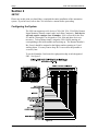
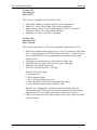
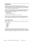
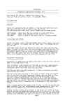
The front panel is used to setup, program and run the shows. It also displays error
and status messages to the user. The front panel incorporates up to nine manual
override switches used for emergency manual control. These are rocker type
switches and their general functions should be obvious to the operator. All
manual controls circumvent the electronic circuitry giving the user the ability to
control the major functions in the event of an automation failure. The manual
control functions are listed below:
1.
2.
3.
4.
5.
6.
7.
8.
9.
PROJECTOR - Maintained ON/AUTO
LAMP - Maintained
CHANGEOVER - Momentary OPEN/CLOSE
LENS - Momentary FLAT/SCOPE
LENS - Momentary SPECIAL
CURTAIN - Momentary OPEN/CLOSE
HOUSE LIGHTS - Momentary UP/DOWN
STAGE LIGHTS - Momentary UP/DOWN
AUXILIARY - Momentary ON1/ON2
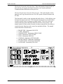
Figure 1
4
Strong International
CNA-100 Automation Manual
System Overview
Keypad and Display
Program Number
Displays the program number to run or edit. Use the up and down cursor keys to
select the program number. Up to nine unique programs can be saved.
Cue Number
Displays the show cue number. During programming use the up and down cursor
keys to select the cue number to edit. Up to nine cues can be programmed for a
show.
Programming Keys
These keys are used to program the sound, lens, masking, lights, intermission,
curtain call and end of show. LEDs are on each key. The LED is "on" indicating
the present state of the output during a show.
Program Edit Key
This key is used to enter the program edit mode allowing the user to build new or
alter existing programs. The LED is on when "program edit" is active. The user
may edit any program during a show or between shows.
Start Key
This key is used to start or restart a show. The LED on the start key will "blink"
when the show is ready to start or ready to restart. The LED is "on" when the
show is running, and "off" when the show is stopped.
Stop Key
This key is used to stop a show. The LED on the stop switch is "on" when a show
is stopped, due either to a "local" or "remote" stop input or a fault.
Sync Key
This key is used to activate the automation for synchronous (interlock) operation.
The sync LED will be "on" indicating the automation is in sync mode.
Sync Loop Number
This displays the Sync Loop number. Use the up and down cursor keys to change
the loop number. Up to 9 different loops can be on the sync network. 0 disables
the machine from sync operation. The user is prevented from changing the Sync
Loop number when sync is enabled with the Sync Key.
Strong International
5
System Overview
CNA-100 Automation Manual
Fault Status LEDs
These LEDs display the status of the fault conditions: Film Presence, Film
Motion and Xenon Fault. The LEDs are "off" when there is no fault present.
When a fault exists, the LED will "blink" rapidly.
Power Switch
Supplies power to the automation main controller and termination panels.
Fault Defeat Key
This key will defeat or bypass the fault inputs (film presence, film motion and
xenon lamp). This key is normally used for testing the projection equipment or
newly edited programs. It is not recommended for normal operation. The LED
will "blink" when the Fault Defeat is activated.
Alarm Cancel Key
This key will cancel the local alarm and all remote alarms. This key is also used
to clear any of the latched faults. Pressing the Alarm Cancel key once will
cancel the alarm. Pressing the key again will clear the fault condition.
Cue Input Key
This key provides a manual cue input. This is similar to the cue input from the
electronic cue detector or pick off. This key is always active during a show.
6
Strong International
CNA-100 Automation Manual
System Overview
Console Termination Panel
This panel supports the input and output termination interface and provides
connections for standard booth functions as listed below:
Outputs:
!
!
!
!
!
Projector Motor; On/Off
Xenon Lamp; On/Off
Changeover; Open/Close
Lens Turret; Flat/Scope/Special
Auxiliary Output; On/Off
Inputs:
!
!
!
!
!
Film Presence
Film Motion
Film Tension
Cue Input
Xenon Fault
Features:
!
!
!
!
!
High power dry relay contact outputs.
High power override connector for plug-in cable to override switches.
Projector motor fuse.
Plug-in I/O CPU Control Board to handle I/O and serial interface.
Terminal Blocks for connection to the console equipment.
The relays and I/O CPU Control Board get their power from the network cable. The
Control Board will plug onto the relay board to provide the I/O and network interface.
Strong International
7
System Overview
CNA-100 Automation Manual
Booth Termination Panel
This panel provides the outputs to control the following functions:
Outputs:
!
!
!
!
!
!
!
!
Top Masking; Flat/Scope/Special
Side Masking; Flat/Scope/Special
Curtains; Open/Close
House Lights; Up, Down, Mid 1, Mid 2
Stage Lights; Up, Down
Environment; On/Off
Slide Projector; On/Off
Sound Processor; Mono, SVA, SR, Digital 1, Digital 2, Aux 1, Non-sync,
Mute, Aux 2, Preamp 1, and Preamp 2.
Inputs:
! Remote Start
! Remote Stop
Features:
! Low power dry relay contact outputs.
! High power dry relay contact outputs for Slide Projector and Environment
Control
! A plug-in I/O CPU Control Board to handle I/O and serial interface.
! Override connector for plug-in cable to override switches.
! Override connector for optional override switches.
! Large terminal blocks for user interface.
This Panel (PC board) will connect to the to the Local I/O Network (LIN). The
outputs can be configured at the PC Host.
The relays and plug-in I/O CPU Control Board get their power from the LIN
cable. This board will generally be mounted in a cabinet on the booth wall, but
can also be mounted in the console next to the Console Termination Panel.
8
Strong International
CNA-100 Automation Manual
System Overview
Single Termination Panel
This panel provides the outputs to control the following functions:
Outputs:
Xenon Lamp; On/ Off
Projector; On/ Off
Changeover; Open/ Close
Slide Projector; On/ Off
Sound Processor; Mono, SVA, SR, Non-Sync, Digital, Aux, And Mute.
Lights; House up, House Mid 1, House Mid 2, House Down, Stage Up,
Stage Down.
! Curtain; Open/ Close
! Masking; Flat/ Scope/ Special
! Lens; Flat/ Scope/ Special
!
!
!
!
!
!
Inputs:
!
!
!
!
!
Film Motion
Film Presence
Film Tension
Cue
Xenon Fault
Features:
! Low power dry relay contact outputs.
! High power dry relay contacts for Xenon Lamp, Projector Motor,
Changeover Open/ Close, and Slide Projector.
! A plug-in I/O CPU Control Board to handle I/O and serial interface.
! Override connector for plug-in cable to override switches.
! Override connector for optional override switches.
! Large terminal blocks for user interface.
This Panel (PC board) will connect to the to the Local I/O Network (LIN). The
outputs can be configured at the PC Host.
The relays and plug-in I/O CPU Control Board get their power from the LIN
cable.
Strong International
9
Setup
CNA-100 Automation Manual
Section 2
SETUP
Please note at this point you should have completed the entire installation of the automation
system. If you have not, refer to the CNA Installation manual before proceeding.
Configuring the System
The LSN can support up to 64 devices (CNA-100/ 150s, CNA-200s, Remote
Status Monitors, dimmer control cards, and a Host Computer). Each device
will each require a unique Sync Id number. Id 0 is reserved for the Host
PC and Ids 1 through 63 are assigned to CNA-100s and other devices as
necessary. To keep things simple, assign the CNA-100 Ids starting at 1,
corresponding to the house number and working up. The Remote Monitor's
Ids, if used, should be assigned to the higher numbers starting at 62 and
working down. You may want to keep Id 63 reserved for the portable or
secondary host.
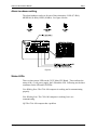
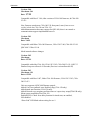
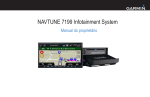
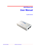
To set the Id number, first locate the eight position dip switch designated
SW1. See figure 2.
Figure 2
10
Strong International
CNA-100 Automation Manual
Setup
Switch Definitions
S1-1
Force Bootloader
On : Force Bootloader.
Off : Normal Use. (Factory Default)
Forces bootloader program at power-up in the event of a RTOS failure.
Note: Version 1.00 and up
S1-2
Supervisory Defaults
On
: Force “Supervisory Defaults” on power up. Default Supervisory
data will be restored on each power up. (Factory Default)
Off : Will not overwrite user-programmed supervisory data on power
up.
If you change any of the default settings with the Host program this
switch must be off or the next time the CNA-100 is powered up all user
settings will be over-written with the defaults.
Note: Version 1.00 through Version 1.08
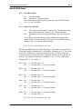
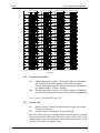
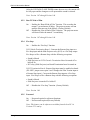
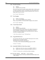
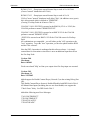
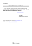
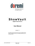
S1-3 through S1-8 are used to set the ID number. The number is represented as a
6-bit binary number which allows for 64 possible ID numbers (0-63). Do not use
0 (zero) as an ID number. It has been reserved for the PC Gateway Interface.
Each bit (switch) has a decimal value. Add up the decimal values to get the ID
number. For example, ID number 15 would be 8+4+2+1=15 or a DIP switch
setting of 001111. See Figure 3.
S1-3
On : 1 Decimal value = 32
Off : 0 Decimal value = 0 (Factory Default)
S1-4
On : 1 Decimal value = 16
Off : 0 Decimal value = 0 (Factory Default)
S1-5
On : 1 Decimal value = 8
Off : 0 Decimal value = 0 (Factory Default)
S1-6
On : 1 Decimal value = 4
Off : 0 Decimal value = 0 (Factory Default)
S1-7
On : 1 Decimal value = 2
Off : 0 Decimal value = 0 (Factory Default)
S1-8
On : 1 Decimal value = 1 (Factory Default)
Off : 0 Decimal value = 0
Note: Version 1.00 through Version 1.08
Strong International
11
Setup
CNA-100 Automation Manual
Figure 3
S2-1
Front Panel Overrides
On
: Enable front panel overrides. The Sound, Lights, Lens/Masking
and Auxiliary front panel switches will override the outputs
without affecting the program. The next instruction will override
any manual changes. (Factory Default)
Off : Disable front panel overrides. The Sound, Lights, Lens/Masking
and Auxiliary front panel switches are only used for programming.
Note: Version 1.00 through Version 1.08
S2-2
Curtain Call
On
: Enables the new Curtain Call function and overrides the original
Curtain Call function.
Off : Original Curtain Call function. (Factory Default)
Place the Curtain Call cue at a distance before the next cue that is equal to
the curtain close time. When the CNA-100 sees the Curtain Call cue, the
curtains begin to close, the changeover closes and sound is muted. At the
next cue, the curtains will begin to open.
12
Strong International
CNA-100 Automation Manual
Setup
After the CURTAIN CLOSE TIMER counts down to zero, the curtain will
be fully open and the changeover will open and the sound is selected.
Note: Version 1.07 through Version 1.08
S2-3
Run Til’ End of Film
On
: Enables the “Run til End of Film” function. This overrides the
normal 7 second motor off delay. The projector motor will run
until the film runs out of the failsafe. (Factory Default)
Off : Disables the “Run til End of Film” function. The projector motor
will shut off after the normal 7 second delay.
Note: Version 1.07 through Version 1.08
S2-4
Fire Stop
On
: Enables the “Fire Stop” function.
39331 Booth Termination Board - Converts the Remote Stop input to a
Fire Stop input and the Slide Projector relay (K13) to a Fire Stop output.
Fire Stop acts like a Remote Stop with the following exceptions:
C Sound is Muted.
C Slide Projector on 39330 Console Termination Board is turned off or
held off on.
C K13 relay (Slide Projector) on Booth Termination board is turned on.
39332 Termination Board - Remote Stop input must be enabled on board.
(W1-OPT1 jumper across pins 2 and 3 changes the Film Tension input to
a Remote Stop input.) Converts the Remote Stop input to a Fire Stop
input. Fire Stop acts like a Remote Stop with the following exceptions:
C Sound is Muted.
C Slide Projector is turned off or held off.
Off : Disables the “Fire Stop” function. (Factory Default)
Note: Version 1.08
S2-5
Password
On : Password required to edit most functions
Off : No Password required (Factory Default)
Note: This feature can be software overridden from the host PC. In
Versions 2.15 and up
Strong International
13
Setup
CNA-100 Automation Manual
S2-6
Check Focus Delay
On : Enabled
Off : Disabled (Factory Default)
The Check Focus feature alerts the operator that the show is about to start.
The alarm will begin to sound 7 seconds prior to the show starting. This
gives the operator time to make any quick adjustments and to insure the
image on the screen is in focus.
Note: Version 2.030 and above
S2-7
Event Logging
On : Enables Event logging
Off : Event Logging Disabled (Factory Default)
Writes a log of events to a file on the HOST computer when enabled.
Note: Version 2.040 and up
S2-8
Content Player Enable
On : Enabled
Off : Disabled (Factory Default)
This switch allows the eCNA to interact with a digital content player.
Serial commands exchanged between the content player and CNA
automation allows the digital projector and film projector to share the
screen in a coordinated manner
* See CAI user Guide, Version: 2.090 and above.
S3-1
Program Edit Password
On: Password required key only operational when password is entered,
Programs can be viewed but not edited.
Off: No Password required to edit programs
“View Only” mode is indicated by flashing program edit LED.
Version: 2.11 and Up
S3-6
Enable RCM/ RSM-10 “Check Focus Alarm”
On : Disables the Check focus alarm on the RSM-10, RCM-10
Off : Enables the Check Focus alarm on the RSM-10, RCM-10
Version 2.15 and up only, see check focus delay description.
S3-2 to 3-5, S3-7 and 3-8
Always Off (Factory Default)
These Switch Positions are currently undefined and should remain in the
“OFF” position.
14
Strong International
CNA-100 Automation Manual
Setup
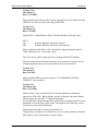
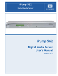
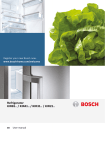
Alarm Loudness setting
The alarm loudness can be set for one of three intensities; LOW (87 dBA),
MEDIUM (94 dBA), HIGH (98 dBA). See figure 4 below.
Figure 4
Status LEDs
There are three status LEDs on the 39325 Main CPU Board. These indicate the
status of the +5 volt power supply, the LSN and the LIN. Following are the three
conditions for the LIN and LSN LEDs:
Fast Blinking Rate: The CNA-100 computer is working and is communicating
properly.
Slow Blinking Rate: The CNA-100 computer is working, but is not
communicating.
Off: The CNA-100 computer has a problem.
Strong International
15
Setup
CNA-100 Automation Manual
Programming the CNA-100
Programming is accomplished with the Programming keys and the Program and
Cue numbers. The CNA-100 gives the user the ability to build and store up to 9
different programs. Each Program can use up to nine cues.
The following steps describe how to edit a program:
1. Press the PROGRAM EDIT key to activate the edit mode. The PROGRAM EDIT
LED will toggle "on". The CUE up and down arrow keys are enabled and the
PROGRAM and CUE displays will stop blinking if show is in progress.
2. Select the program to edit with the PROGRAM up or down arrow keys.
3. Program the Sound, Lens and Lights for each cue using the programming
keys. Program the Auxiliary outputs (OUT 1 through OUT 4) if an ‘Aux
Board’ is connected to the system. One or more of these outputs can be on at
a time.
4. Use the SHOW END key to indicate the end of the program.
5. Select a different program to edit or press the PROGRAM EDIT key to deactivate edit mode. The PROGRAM EDIT LED will toggle "off". The PROGRAM
number and CUE number up and down arrow keys will be disabled and the
displays will slowly blink if the show is in progress.
Following are some simple rules to remember when programming:
1) Programming a SHOW END cue locks out subsequent cue numbers, keeping
you from scrolling to a larger cue number.
2) You may edit any program while a show is in progress (including the program
that is running).
3) When a show is in progress and you are not in the PROGRAM EDIT mode the
PROGRAM and CUE number up and down arrow keys are disabled.
4) Use of HOST PC and software will provide the most user-friendly interface
to the CNA-100 as well as provide access to multiple options not available
through the keypad and 7 segment display interface on the front panel.
Pressing the STOP and START keys simultaneously will escape a running show,
this can be used while troubleshooting or installing the system.
16
Strong International
CNA-100 Automation Manual
Setup
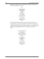
The INTERMISSION and CURTAIN CALL Keys
These are two special programming keys that allow the user to easily program a
Show Intermission and a Curtain Call. The INTERMISSION KEY is used to program
a show intermission at the selected cue. The cue then initiates the intermission
sequence as follows:
Changeover Close
Lights
Sound
Curtain Close
--------------------------7 second delay
--------------------------Xenon Lamp Off
Projector Motor Off
Slide Projector On
The Intermission is terminated and the show is re-started either by a START input
(remote or local) or a CUE input (remote or local). If the show is re-started by a
START input, only the projector motor and lamp are turned on. The next film cue
will initiate the show start sequence. The show start sequence is as follows:
START
--------------------------Xenon Lamp On
Projector Motor On
--------------------------Cue n
--------------------------Lens/Masking
Lights
Curtain Open
--------------------------7 second delay
--------------------------Slide Projector Off
--------------------------1 second delay
--------------------------Changeover Open
Sound
Strong International
17
Setup
CNA-100 Automation Manual
If the show is re-started with a CUE input, there is no need for a show start cue.
The show start sequence is as follows:
CUE
--------------------------Xenon Lamp On
Projector Motor On
Lens/Masking
Lights
Curtain Open
--------------------------7 second delay
--------------------------Slide Projector Off
--------------------------1 second delay
--------------------------Changeover Open
Sound
The "Curtain Call" function will issue a curtain close at a selected cue. For
example, suppose you wanted your curtains to close and the end of your trailers
and open back up at the start of your feature presentation. You would place a cue
at a distance before the end of the trailer that is equal to the curtain close time and
another cue at the beginning of the feature. The sequence of events are as
follows:
Cue n (with Curtain Call)
--------------------------Curtain Close
Sound (if programmed)
Lights (if programmed)
--------------------------Cue n+1
--------------------------Lens/Masking
Changeover Close
Lights
Curtain Open
--------------------------7 second delay
--------------------------Changeover Open
Sound
18
Strong International
CNA-100 Automation Manual
Setup
Operating the CNA-100
In the "Ready to Run" state, the FILM PRESENCE LED will be "off", and the START
LED will be blinking. Select the program 1 through 9, that you want to run with
the up/down arrow keys. Press the START switch to start the show. The START
LED will toggle "on".
When a show is running, the current states of the Sound, Lens, Lights and
Auxiliary will be shown with the LEDs "on". The cue number displayed is the
next cue the CNA-100 is waiting to see.
Soft Manual Overrides
During run mode, pressing any of the Sound, Lens, Lights or Auxiliary keys will
drive the output to that state. Note: This will not alter the saved program. At the
next cue the program will override any manual changes. This option is only
available when the internal DIP switches are configured to allow soft overrides.
Synchronous Operation
The CNA-100 systems are capable of running film synchronously in a multiprojector booth. The CNA-100 can be programmed for any one of nine sync
loops. This allows for up to nine different sync loops on the network at one time.
Pressing the SYNC key will activate the sync operation and disable the up/down
arrow keys. (This prevents the machine from joining another sync loop that may
be running and causing a fault on those machines when it drops off the loop.) To
change the SYNC LOOP number, press the SYNC switch to deactivate. Set the loop
number with the up and down arrow keys and press the SYNC switch again to
activate. The LED on the SYNC switch indicates whether sync mode is active or
not.
To run in sync the following conditions must be true:
1. A sync cue must be added to the beginning of the film. This is the first cue
that is seen by the automation. It acts to initiate the start up sequence for each
machine.
2. Sync Mode on each automation in the loop must be enabled.
3. The sync loop number on each automation in the loop must be the same.
To begin a movie, insure that the sync cue is positioned somewhere before the cue
detector on the first machine. Press the [START] switch on any machine in the
loop. All projectors will start simultaneously. As the sync cue passes through
each projector, the show start sequence will initiate.
At the end of the show each machine will shut down independently as the tail of
the film runs out of the projector. On endless loop systems all projectors will
continue to run until the last machine sees the end cue. At that time all projectors
will shut down simultaneously.
Strong International
19
Setup
CNA-100 Automation Manual
System Status Messages
The CNA-100 contains a list of status messages that can be displayed due to
various internal or external conditions. Most of these messages displayed indicate
system faults. There are also some internal power up and reset diagnostic
messages, most of which will not and should not be displayed under normal
operating conditions.
Fault Condition Messages
The Fault Condition messages can be divided into three categories: Internal
memory faults, run-time faults and failsafe faults.
Memory Faults
The internal memory faults are generated when there is a "checksum" error.
Briefly, a checksum is an arithmetic sum of the contents of memory that is stored
in the memory itself and is re-computed and checked each time the CNA-100 is
powered up. Each of the Programs (1 through 9) and the System Parameters have
a checksum. The fault messages are displayed and "blinked" rapidly on the three
digital displays.
Message
Description
P01
P02
P03
P04
P05
P06
P07
P08
P09
PAr
Program 1 Checksum Fault
Program 2 Checksum Fault
Program 3 Checksum Fault
Program 4 Checksum Fault
Program 5 Checksum Fault
Program 6 Checksum Fault
Program 7 Checksum Fault
Program 8 Checksum Fault
Program 9 Checksum Fault
System Parameters Checksum Fault
If any of the Program memory faults are displayed on power up, clear the fault
by pressing the ALARM CANCEL key. Press the PROGRAM EDIT key to enter the
edit mode. Cursor to the program that has the checksum error. Scroll through the
program to verify it. If all the steps look okay, press any key to re-calculate the
checksum. Press the PROGRAM EDIT key again and cycle power to verify that
there are no other checksum errors.
A System Parameters memory fault will be displayed if there is a checksum error.
This error must be cleared from the Host PC, by copying the system parameters
from the Host Program to the CNA-100. If you are not using a Host PC, the
system will be using the default parameters and can not issue a System
Parameters Checksum Fault.
20
Strong International
CNA-100 Automation Manual
Setup
Run-Time Faults
These three messages will be displayed if there are the following communications
faults.
Message
Description
LIn
LSI
LSC
Local I/O Network Fault
Local Sync Interlock Fault
Local Sync Communications Timeout Fault
The Local I/O Network Fault is caused due to a loss in communications with a
Local I/O Network device or another network problem. This could be the Booth
Termination Panel, Console Termination Panel or other I/O Network device or a
wiring problem.
A Local I/O Network fault will cause the CNA-100 to display "L I n". This fault
will cause a shutdown during a show or prevent a show start between shows.
This fault is latched and you are required to press the ALARM CANCEL key to clear
the fault. Although this will cancel the fault and allow a show to start, there is a
problem with the Local I/O Network or one of the devices and it must be repaired.
A Local Sync Interlock Fault is caused when either a master or one of the slaves
in the sync loop has lost it’s sync input (sync switch). All CNA-100s on the sync
loop will display “L S I” and sound their alarms. This message will also be
displayed if one of the units on the loop had a “watchdog reset”. If this was the
case, all units will display this message except for the one that had the watchdog
reset.
A Local Sync Communications Fault is caused when there is a loss of
communications with a unit on the sync loop. This could be due to a loss of
power of the master or one of the slaves on the loop. In this case all units on the
sync loop would display “L S C” except for the one that lost its power. This fault
can also be caused by defective wiring, such as an open or short on the LSN
communications link.
Strong International
21
Setup
CNA-100 Automation Manual
Sync Interlock Failsafe Fault
This fault indicates the master or one of the slave CNA-100s has a failsafe fault
that is preventing the interlock loop from resuming a show. The following
message is displayed to indicate this fault.
Message
Description
LSr
LSr
LSr
Not Ready To Resume Fault
Need Master To Resume Fault
Not Ready To Run
The Not Ready To Resume Fault indicates that the automation cannot start a show
because a least one of the CNA-100 remotes are not in the “Ready to Resume”
condition.
The Need Master To Resume Fault indicates that there is no master. The master
may be lost if the communication wires are disconnected, power is lost or the
sync input (sync switch) is not enabled at the master.
The Not Ready To Run Fault indicates that the automation cannot start a show
because a least one of the CNA-100 remotes are not in the “Ready to Run”
condition
Event and Show Logs
When running Host software the CNA-100 is capable of sending data over the
LSN to a Host PC. This is a historical record of automation activity including
faults, starts, stops, cues and other occurrences. Show logs contain data
specifically about a particular show, this data can include show numbers, events
and times that the events occurred, total down time, and many other important
parameters. See the Host manual for more information on event and show logs.
Program and Configuration Copy Functions
The Host software package allows the user to copy individual programs and
configuration details from and to your CNA-100. Due to limitations set by the
front panel’s attributes, the Host package must be used to access these functions.
Supervisory
Supervisory configuration is only accessible via the Host program, system
variables such as lighting levels for the QDC-400 and sound configuration on the
RVC-5, as well as system settings including Delays, password, and output
configurations can all be set up here. See the Host user guide for further
information on these functions.
22
Strong International
CNA-100 Automation Manual
Setup
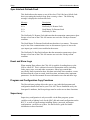
Power Up Messages
Upon power up, the CNA-100 will display a series of messages. The following
messages should be displayed at power up:
Message
Description
215
105
PUP
Version Number (2 seconds)
Checksum Number (2 seconds)
Power Up Reset (2 seconds)
These messages will be displayed in this order each time the CNA-100 is powered
up. Each message is displayed for about 2 seconds. The first message is the
software version number (version 2.15). The second is the software checksum
number, and the last message indicates to the user that it is a power up condition.
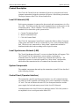
Additional Software
CineNet Host Software Package
The CNA-100 automation is optimally configured and used with the CineNet
HOST software package. The Host program allows setup, data transfer and
programming in a user-friendly format. Additional hardware and software is
required. First there must be a Host Computer, this can be any DOS-based PC
with either 1 free ISA slot or an RS-232 Serial port that is not in use, installed on
that PC there must be CineNet Host networking software. This software allows
the PC to interface with the CNA. The only additional piece of hardware required
is a network controller. This can be in the form of a ISA card installed in the PC,
or a convenient external package such as the VNC or PCI-64 network interface.
See the CineNet HOST user manual for further details on installation.
Host software provides Event logging, both LIN and LSN Network status,
configuration, and programming/ copy functions as described in previous
sections.
CineSuite Software Package
The CineSuite software package is a more advanced version of HOST software
including three software applications:
CineSuite Manager: This is the main user interface. When creating CNA
programs, settings CNA supervisory functions or monitoring CNA operations,
this is the application that will be used.
CineSuite Router: The CineSuite Router is used to manage traffic between the
various CineSuite applications. Users only need to set the client application to
point to the computer that has the CineSuite router running and it can then
communicate with all other clients connected to the same router.
Strong International
23
Setup
CNA-100 Automation Manual
CineNet Driver: This is the software application that connects the CNA Gateway
and automations to the computer.
The CineSuite software operates over TCP/IP communications protocol meaning
that it can be used in conjunction with the internet via a modem or any ethernet
connection. It allows remote access to the automation network and provides a
means of remotely monitoring devices on the LIN.
CineSuite Reporter software has a full color interface for quick identification of
remote problems. Reporter can also email status reports managerial personnel and
generate reports over long periods of time in order to quantify efficiency in staff
and equipment.
CineSuite similarly requires a Host PC and a hardware interface device. The Host
PC must be at least a 486/66Mhz running windows 95 or above. The CineSuite
package is constantly under development with new features being added
regularly. See the CineSuite Guide for additional information.
24
Strong International
CNA-100 Automation Manual
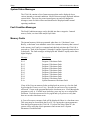
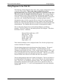
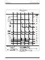
Timing Diagrams
Timing Diagrams for the CNA-100
The following Timing Diagrams show timer values, output configurations and cue
events for all the outputs. Timers and output configurations such as
pulsed/maintained, power up and fault conditions are defaulted on the CNA100, and can only be changed with the Host Program. These timing diagrams
can be extremely useful to help understand the operation and capabilities of the
CNA-100. The first timing diagram shows the “Standard Operation” from power
up to show end. Standard Operation implies a running a program with no
interruptions (stop or faults) or special effects (curtain call or intermission). The
defaults for each outputs are indicated in the last column of the timing diagram.
Default timer values and pulse durations are indicated in the bottom margin of the
timing diagram. The diagram indicates automatic and programmed outputs.
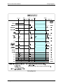
The second timing diagram shows the Fault/Stop Shutdown and Restart
Sequence. The area of interest is the shaded portion of the diagram. This shows
the default ‘Fault-to’ conditions:
Projector Motor and Lamp = OFF
Slide Projector = ON
Changeover = CLOSE
Sound = NON-SYNC
House Lights = UP
Stage Lights = UP
These default conditions can be configured in the CNA-100 Set-up Supervisory
section of the Host PC Program.
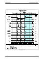
The third timing diagram shows the Intermission Stop Sequence. The area of
interest is the shaded portion of the diagram. At the Intermission cue the
Changeover and Curtain will close. Seven seconds later the Projector Motor will
shut off and the Slide Projector will turn on. Sound, Lights and Out 1, 2, 3, and 4
can be programmed for any state during the intermission. A Restart will start the
Projector Motor and a film cue will initiate the show start sequence.
The last timing diagram shows the Curtain Call Sequence. The area of interest is
the shaded portion of the diagram. At the Curtain Call cue, the curtain begins to
close. The ‘next’ cue will begin to open the curtain. The ‘curtain close time’ is
determined by the distance between the curtain call cue and the next film cue.
Sound, Lights and Out 1, 2, 3, and 4 can be programmed for any state during the
Curtain Call.
Strong International
25
Timing Diagrams
CNA-100Automation Manual
Timing Diagram 1
26
Strong International
CNA-100 Automation Manual
Timing Diagrams
Timing Diagram 2
Strong International
27
Timing Diagrams
CNA-100Automation Manual
Timing Diagram 3
28
Strong International
CNA-100 Automation Manual
Timing Diagrams
Timing Diagram 4
Strong International
29
Addendum
CNA-100 Automation Manual
Addendum
Software Changes
This section details the CNA-100 software changes.
Version: 1.05
Checksum: 210
Date: 7/15/97
This version requires Host V1.003 and is compatible with CNA-200 V1.006.
1. Aux Output on Console Termination Board now follows "Slide Projector"
output.
2. Lens and Masking now support programmable "Power Up" default.
3. I/O Communications now "re-sends" setup data to I/O devices when
System Parameters is updated. (Sound C/O Pulse time.)
4. Added "(t)" and "©" to Sync protocol to indicate "Timed" or "Clock" Start
mode.
5. Stop key now works the same everywhere - forcing switch to "Show Hold"
mode (to other controls).
6. Added "Check Focus" beep to indicate Clock Start or Timed Start from
another control.
Version: 1.06
Checksum: 216
Date: 9/17/97
This version requires Host V1.004 and is compatible with CNA-200 V1.007.
1. Added support for newly designed MCD-35 Cue Detector for Local I/O
Network (LIN).
Note the CNA software "Auto Detects" the MCD-35 the first time it responds
to a poll. Once this board is detected the "Motion" and "Presence" inputs on
the Console Board are then ignored. It would be a good idea to leave the
Console Board inputs "open" rather than "shorted" to cause a fault in the event
that the MCD-35 board does not respond to polls on power up. (Not a
requirement, just a suggestion...)
2. Increased Motion Fault time from 2 seconds to 3 seconds.
30
Strong International
CNA-100 Automation Manual
Addendum
Version: 1.07
Checksum: 23
Date: 2/02/97
This version is compatible with CNA-200 V1.009.
1. Added S2-2 "Enhanced Curtain Call" DIP switch configuration.
2. Added S2-3 “Run til End of Film” DIP switch configuration.
3. Added “Resume-bypass” of the Sound Changeover Delay. The Sound
Changeover Delay is now bypassed for a Resume.
4. Data Entry now shows "next state" of program.
Version: 1.08
Checksum: 103
Date: 10/16/98
This version requires Host V1.005 and is compatible with CNA-200 V1.011.
1. Added LIN communications support for new ACP-50 Auxiliary Control Panel
device. Added support for ACP-50 Volume & Mute Keys. Volume keys are
however disabled for this version pending the development of the remote
volume control.
2. Selecting new sound formats now clears the new "Mute" flag.
3. Sound and Lens now pulse when set to the "same" state again.
4. Added Fire Stop Option Dip switch:
S2-4 OFF = Normal Stop, ON = Fire Stop
This new "Fire Stop" option:
a. Stops the Show,
b. Forces Sound to Mute,
c. Forces Console Slide Projector off,
d. Forces Booth Slide Projector On (new fire stop output).
e. Forces all other outputs to their "Fault To" state.
When S2-4 is Configured for "normal" operation both Slide Projector
outputs perform the "Slide Projector" function and the Remote Stop simply
stops the show if it is in progress (both same as in previous version).
5. Check Focus Alarm now only follows others on our SYNC loop if our SYNC
switch is enabled.
Strong International
31
Addendum
CNA-100 Automation Manual
Version: 2.00
Checksum: 244
Date: 2/7/99
Compatible with Host V.1.06, older versions of CNA 100 firmware, & CNA-200
V1.011.
New firmware auto-detects CNA-100/ 150 front panel, same firmware now
resides in both the CNA-100 and CNA-150
Added demonstration data entry support for QDC-400, there is no control or
communications support implemented however
Version: 2.01
Checksum
Date: 3/4/99
Compatible with Older CNA-100 Firmware, CNA-150 V2.00, CNA-200 V1.011
QDC-400 V2 Host V1.06
Made internal software changes.
Version: 2.02
Checksum:
Date: 4/27/99
Compatible with older CNA-100, CNA-150 V2.02, CNA-200 V1.011, QDC V3
Dimmer Setup now allows 0-99 Seconds (Previous version allowed 0-60)
Version: 2.03
Checksum: 120
Date: 6/22/99
Compatible with Host 1.007, Older CNA-100 firmware, CNA-150 V2.03, CNA200 V1.013
Unit now supports 4 QDC-400 Dimmer controls.
Added Cue Learn (manual/ auto/ disabled) flag (CNA-150 only).
Added timed start function (CNA-150 only).
Added Network copy programs and learn times w/ supervisory setup(CNA-150 only).
Menu system restructured for CNA-150
Enabled SW2-6 Check focus delay function for timed start, on=enabled,
Off=disabled
“Show End” LED blinks when waiting for cue 9
32
Strong International
CNA-100 Automation Manual
Addendum
Version: 2.04
Checksum:
Date: 8/23/99
Compatible with Host V1.007, Older CNA-100 versions, CNA-150 V2.040,
CNA-200 V1.014, RVC10 V1, QDC-400 V3+4
Added event logging via SW2-7 (on=enabled, off=disabled)
Added measurement of "Unscheduled Down Time". This is simply the number of
seconds that a show is stopped due to a Major Fault or by Manual "Stop" (key or
input).
Version: 2.05
Checksum: 50
Date: 2/4/2000
Compatible with Host V1.010, Older CNA-100 firmware (V1.08), CNA-200
V1.016, QDC-400 V3+4.
Added support for Flash updates through Host SW1-1 Now forces Bootloader in
the event of RTOS failure.
Added “remote reset” power up message for occasions where a remote reset is
invoked.
Version: 2.06
Checksum:
Date: 5/11/2000
Compatible with Host V1.010, Older CNA-100 firmware (V1.08), CNA-200
V1.016, QDC-400 V3+4.
-Improved keypad cue input functionality, (end segment “MEND” now latches
keyboard cues “ICUEKL” for more dependable operation)
-Moved sound and lights default code to the start stop key abort logic and
removed it from the DRMABT routine. This prevents Show start from forcing
House and Staged lights up and sound to Non-sync when waiting for Cue 0.
Version: 2.07
Checksum: 120
Date: 6/28/2000
Compatible with Host V1.011, Older CNA-100 firmware (V1.08), CNA-200
V1.019, QDC-400 V3+4.
Added support for new "FIRESTOP" input bit from RCM10 V2.020 Sync flags.
Compatibility and functionality are described below. Note that "Remote Stop"
and "Fire Stop" are two different functions:
Strong International
33
Addendum
CNA-100 Automation Manual
RCM10 V2.01 -Estop input asserts Remote Stop to each of it's 10 CNA's
(Causes "normal" shutdown in all CNA's.)
RCM10 V2.02 -Estop input asserts Remote Stop to each of it's 10
CNA's.(Causes "normal" shutdown in all older CNA's.) In addition a new (spare)
bit is also asserted which is defined as "FIRESTOP".
(Causing "FireStop Faults in all newer CNA's.)
CNA-200 V1.018 -If ESTOP is asserted at the RMC10 (V2.01 or V2.02) the
CNA-200 performs a normal "REMOTE STOP".
CNA-200 V1.019 -If ESTOP is asserted at an RMC10 V2.01 the CNA-200
performs a normal "REMOTE STOP".
-If ESTOP is asserted at an RMC10 V2.02 the CNA-200 asserts it's FireStop
Fault.
All combinations are compatible - you will either get the "old" operation or the
"new" operation. To get the "new" operation, you need to update both the RCM
and the CNA software.
Note the SW2-4 operation is unchanged in this software release - it is simply
restated here for convenience since there is now an additional input that can set
the Fire Stop Fault.
Version: 2.08
Checksum:
Date: 6/8/2001
Fixed scan related "blip" on Non-sync output when Fire Stop input was asserted.
Version: 2.09
Checksum: 12
Date: 9/25/2002
Added support for Kodak Content Player (Network 2) on the existing Debug Port
(P6).
This Kodak Content Player feature is Enabled/Disabled with DIP Switch 2 bit-8.
All Manual Start Inputs (including the new one from Kodak) now support the
"Check Focus" delay. See DIP Switch 2 bit-3.
Added the following new Error Messages:
"CAI COM TIMEOUT"
"CP COM TIMEOUT"
"CP NOT IN AUTO"
"CP NOT READY"
34
Strong International
CNA-100 Automation Manual
Addendum
Version: 2.10
Checksum: 12
Date: 10/31/2002
Made internal improvement with “firestop” input function. (Fire Stop Fault logic
(FIRESF) now always sets the mute flag (VMUTEF)).
Version: 2.11
Checksum: 50
Date: 1/16/2003
Added SW3-1 configuration to enable "Program Edit Key Password" logic.
SW3-1:
ON
OFF
"Program Edit Key Password" required.
"Program Edit Key Password" is not required.
When configured with "SW3-1 ON", the software supports both the original
"Edit" mode and a new "View Only" mode.
The "View Only" mode is indicated by the "Program Edit LED" blinking.
This new mode allows the Feature Programs to be viewed by anyone. However,
changing programs (may) now require entering the correct password.
Version: 2.12
Checksum:24
Date 5/16/2003
Added CLINK2TMR to prevent erroneous "CAI COMMUNICATIONS
TIMEOUT" error messages.
Version: 2.13
Checksum: 248
Date: 10/21/2003
Added “chksys” logic to data entry save of system parameters eliminating
unnecessary LIN traffic. Where updates are only performed when data changes
Added support for new QDC v7 Optional front panel.
Screens that edit system parameter data are aborted by communications if system
parameter is received from a QDC board. This applies to the following screens:
setup CNA system and Setup dimmer.
Added support for QDC overrides from boards 2-4.
Changed power up logic to now finish move to save system parameters from the
QDC update if it was interrupted by a power failure.
Strong International
35
Addendum
CNA-100 Automation Manual
Version: 2.14
Checksum: 50
Date 4/20/2004
HDLCS no longer clears HOSTUP flag. (made the CNA request Host ID and then
Send machine status via LSN
Reworked software to prevent unwanted watchdog tripping when debugging.
Added Support for RVC-5, “3-sound” in supervisory, “3-sound programs” to setup menu, and “3-sound level” to control menu.
Enhanced support for ACP 50 volume keys and display.
The rising edge of firestop fault logic now forces house and stage lights bright.
This lets the overrides function as expected. Previously the lights were not forced
bright if a fault was present.
Version: 2.15
Checksum: 105
Date 1/ 19/ 2005
1- Made password dip switch software configurable via the host program. Note
that the latest version of host is also required.
2- SW 3-6 enables/ disables the RSM-10/ RCM-10's “Check Focus Delay” alarm.
Off enabled and On is disabled
3- Added programmable power up states for masking and Sound.
Added programmable Fault to settings for: Lens, Masking, Sound, House lights,
and Stage Lights. These are defined through the host program.
Made the CNA-100 more like the CNA-200 by reworking the feature start time
routine. Reworked the Call to log automatic Cue 0 event.
Bootloader Changes:
Date: 2/4/2000
Version: 1.000
Checksum: 40157 (Base 10)
Initial bootloader used in CNA system.
1. Created this Boot Loader Program to load the following programs into
FLASH:
CNA-100 V2.05
CNA-150 V3.050
CNA-200 V1.016
2. This program uses LSN Network Device Type = 4 (CNABOOT).
3. Now supports LSN FLASH update Network commands ($40 to $43).
36
Strong International
CNA-100 Automation Manual
Addendum
Date: 5/9/2000
Version: 1.001
Checksum: 44570 (Base 10)
1. Moved "LDY #SWAPCNT" up 3 lines in Calculate Checksum routine
(CALCPCHK) to increase the rate the watchdog is toggled. Should not have been
a problem.
2. Now toggles watchdog in FL_PROGBK routine since a byte write may take as
long as 60 milliseconds
Date: 9/16/2002
Version: 1.010
Checksum: 44558 (Base 10)
Latest versions at this time:
CNA-100 V2.09
CNA-150 V3.090
CNA-200 V1.022
1. Changed "CPE SAVEP,Z" to "CPE 0,X" in FL_PROG routine to correctly
test for "POSSIBLE TIMEOUT OR JUST WENT DONE". The previous logic
might report a write as failed. The logic must be currently taking the earlier
branches - Since there were no reports of this failure from the field at this time.
Date:10/7/2002
Version: 1.020
Checksum: 61822 (Base 10) $F17E
Latest versions at this time:
CNA-100 V2.09
CNA-150 V3.090
CNA-200 V1.022
1. Rewrote FL_ERASE routine. The original interpretation of the multiple sector
erase sequence was wrong - but worked with the FLASH parts at that time ("nonlettered": AM29F010). However the new parts (“lettered” AM29F010B) no
longer accept this interpretation. Basically, the "unlock" portion of the command
should only be issued once, then within 50 microseconds write the Sector Erase
command ($30) to multiple sectors.
2. Reworked the comments for FL_ERASE - Indicating it should only be used to
erase a single sector.
3. Moved call to “PROTFY” in main loop down a few lines from just after “JSR
FL_ERASE” to just after “JSR FL_WAITE”. I don’t think this was a problem,
since this program runs in ram. This change should now let the “FL_ERASE”
routine correctly perform the FLASH Reset function if it is ever necessary.
4. Increased FLASH erase timeout from 15 to 20 seconds.
Strong International
37
Index:
Addendum . . . . . . . . . . . . . . . . . . . . . . . . . . . . . . . . . . . . . . . . . . . . . . . . . . . . . . . . . . . . . . . . . . 30
Alarm Cancel . . . . . . . . . . . . . . . . . . . . . . . . . . . . . . . . . . . . . . . . . . . . . . . . . . . . . . . . . . . . . . . . . 6
Alarm Loudness . . . . . . . . . . . . . . . . . . . . . . . . . . . . . . . . . . . . . . . . . . . . . . . . . . . . . . . . . . . . . . 15
Booth termination Panel . . . . . . . . . . . . . . . . . . . . . . . . . . . . . . . . . . . . . . . . . . . . . . . . . . . . . . . . 8
Bootloader . . . . . . . . . . . . . . . . . . . . . . . . . . . . . . . . . . . . . . . . . . . . . . . . . . . . . . . . . . . . . . . . . . 11
CineNet Driver . . . . . . . . . . . . . . . . . . . . . . . . . . . . . . . . . . . . . . . . . . . . . . . . . . . . . . . . . . . . . . . 24
CineNet Host . . . . . . . . . . . . . . . . . . . . . . . . . . . . . . . . . . . . . . . . . . . . . . . . . . . . . . . . . . . . . . . . 23
CineSuite . . . . . . . . . . . . . . . . . . . . . . . . . . . . . . . . . . . . . . . . . . . . . . . . . . . . . . . . . . . . . . . . . . . 23
CineSuite Manager . . . . . . . . . . . . . . . . . . . . . . . . . . . . . . . . . . . . . . . . . . . . . . . . . . . . . . . . . . . 23
CineSuite Router . . . . . . . . . . . . . . . . . . . . . . . . . . . . . . . . . . . . . . . . . . . . . . . . . . . . . . . . . . . . . 23
CNA Programming . . . . . . . . . . . . . . . . . . . . . . . . . . . . . . . . . . . . . . . . . . . . . . . . . . . . . . . . . . . 16
Console Termination Panel . . . . . . . . . . . . . . . . . . . . . . . . . . . . . . . . . . . . . . . . . . . . . . . . . . . . . . 7
Copy Functions . . . . . . . . . . . . . . . . . . . . . . . . . . . . . . . . . . . . . . . . . . . . . . . . . . . . . . . . . . . . . . 22
Cue Input . . . . . . . . . . . . . . . . . . . . . . . . . . . . . . . . . . . . . . . . . . . . . . . . . . . . . . . . . . . . . . . . . . . . 6
Cue Number . . . . . . . . . . . . . . . . . . . . . . . . . . . . . . . . . . . . . . . . . . . . . . . . . . . . . . . . . . . . . . . . . . 5
Curtain Call key . . . . . . . . . . . . . . . . . . . . . . . . . . . . . . . . . . . . . . . . . . . . . . . . . . . . . . . . . . . . . . 17
Defaults, Supervisory . . . . . . . . . . . . . . . . . . . . . . . . . . . . . . . . . . . . . . . . . . . . . . . . . . . . . . . . . . 11
Description . . . . . . . . . . . . . . . . . . . . . . . . . . . . . . . . . . . . . . . . . . . . . . . . . . . . . . . . . . . . . . . . . . . 3
Edit . . . . . . . . . . . . . . . . . . . . . . . . . . . . . . . . . . . . . . . . . . . . . . . . . . . . . . . . . . . . . . . . . . . . . . . . . 5
Event and Show Logs . . . . . . . . . . . . . . . . . . . . . . . . . . . . . . . . . . . . . . . . . . . . . . . . . . . . . . 22, 23
Fault Conditions . . . . . . . . . . . . . . . . . . . . . . . . . . . . . . . . . . . . . . . . . . . . . . . . . . . . . . . . . . . . . . 20
Fault defeat . . . . . . . . . . . . . . . . . . . . . . . . . . . . . . . . . . . . . . . . . . . . . . . . . . . . . . . . . . . . . . . . . . 6
Intermission Key . . . . . . . . . . . . . . . . . . . . . . . . . . . . . . . . . . . . . . . . . . . . . . . . . . . . . . . . . . . . . 17
Introduction . . . . . . . . . . . . . . . . . . . . . . . . . . . . . . . . . . . . . . . . . . . . . . . . . . . . . . . . . . . . . . . . . . 1
Keypad . . . . . . . . . . . . . . . . . . . . . . . . . . . . . . . . . . . . . . . . . . . . . . . . . . . . . . . . . . . . . . . . . . . . . . 5
LIN, Description . . . . . . . . . . . . . . . . . . . . . . . . . . . . . . . . . . . . . . . . . . . . . . . . . . . . . . . . . . . . . . 3
Loop Number . . . . . . . . . . . . . . . . . . . . . . . . . . . . . . . . . . . . . . . . . . . . . . . . . . . . . . . . . . . . . . . . . 5
LSN, description . . . . . . . . . . . . . . . . . . . . . . . . . . . . . . . . . . . . . . . . . . . . . . . . . . . . . . . . . . . . . . 3
Manual Overrides . . . . . . . . . . . . . . . . . . . . . . . . . . . . . . . . . . . . . . . . . . . . . . . . . . . . . . . . . . . . 19
Memory Faults . . . . . . . . . . . . . . . . . . . . . . . . . . . . . . . . . . . . . . . . . . . . . . . . . . . . . . . . . . . . . . . 20
Network ID . . . . . . . . . . . . . . . . . . . . . . . . . . . . . . . . . . . . . . . . . . . . . . . . . . . . . . . . . . . . . . . . . 11
Operating the CNA-100 . . . . . . . . . . . . . . . . . . . . . . . . . . . . . . . . . . . . . . . . . . . . . . . . . . . . . . . . 19
Operator Interface . . . . . . . . . . . . . . . . . . . . . . . . . . . . . . . . . . . . . . . . . . . . . . . . . . . . . . . . . . . . . 3
Overview . . . . . . . . . . . . . . . . . . . . . . . . . . . . . . . . . . . . . . . . . . . . . . . . . . . . . . . . . . . . . . . . . . . . 2
PCI-64 network interface . . . . . . . . . . . . . . . . . . . . . . . . . . . . . . . . . . . . . . . . . . . . . . . . . . . . . . . 23
Power-Up messages . . . . . . . . . . . . . . . . . . . . . . . . . . . . . . . . . . . . . . . . . . . . . . . . . . . . . . . . . . . 23
Program Number . . . . . . . . . . . . . . . . . . . . . . . . . . . . . . . . . . . . . . . . . . . . . . . . . . . . . . . . . . . . . . 5
Run-Time Faults . . . . . . . . . . . . . . . . . . . . . . . . . . . . . . . . . . . . . . . . . . . . . . . . . . . . . . . . . . . . . 21
Setup . . . . . . . . . . . . . . . . . . . . . . . . . . . . . . . . . . . . . . . . . . . . . . . . . . . . . . . . . . . . . . . . . . . . . . 16
Software Changes . . . . . . . . . . . . . . . . . . . . . . . . . . . . . . . . . . . . . . . . . . . . . . . . . . . . . . . . . . . . 30
Software Revision History . . . . . . . . . . . . . . . . . . . . . . . . . . . . . . . . . . . . . . . . . . . . . . . . . . . . . . 30
Start . . . . . . . . . . . . . . . . . . . . . . . . . . . . . . . . . . . . . . . . . . . . . . . . . . . . . . . . . . . . . . . . . . . . . . . . 5
Status LED's . . . . . . . . . . . . . . . . . . . . . . . . . . . . . . . . . . . . . . . . . . . . . . . . . . . . . . . . . . . . . . . 6, 15
Stop . . . . . . . . . . . . . . . . . . . . . . . . . . . . . . . . . . . . . . . . . . . . . . . . . . . . . . . . . . . . . . . . . . . . . . . . 5
Supervisory . . . . . . . . . . . . . . . . . . . . . . . . . . . . . . . . . . . . . . . . . . . . . . . . . . . . . . . . . . . . . . . . . 22
Switch Configuration . . . . . . . . . . . . . . . . . . . . . . . . . . . . . . . . . . . . . . . . . . . . . . . . . . . . . . . . . . 10
38
Strong International
Sync . . . . . . . . . . . . . . . . . . . . . . . . . . . . . . . . . . . . . . . . . . . . . . . . . . . . . . . . . . . . . . . . . . . . . 5, 19
Sync cue . . . . . . . . . . . . . . . . . . . . . . . . . . . . . . . . . . . . . . . . . . . . . . . . . . . . . . . . . . . . . . . . . . . . 19
Sync Failsafe Fault . . . . . . . . . . . . . . . . . . . . . . . . . . . . . . . . . . . . . . . . . . . . . . . . . . . . . . . . . . . . 22
Sync operation . . . . . . . . . . . . . . . . . . . . . . . . . . . . . . . . . . . . . . . . . . . . . . . . . . . . . . . . . . . . . . . 19
Synchronous operation . . . . . . . . . . . . . . . . . . . . . . . . . . . . . . . . . . . . . . . . . . . . . . . . . . . . . . . . 19
Table of Contents . . . . . . . . . . . . . . . . . . . . . . . . . . . . . . . . . . . . . . . . . . . . . . . . . . . . . . . . . . . . . . 5
Termination Panel, Booth . . . . . . . . . . . . . . . . . . . . . . . . . . . . . . . . . . . . . . . . . . . . . . . . . . . . . . . 8
Termination Panel, Console . . . . . . . . . . . . . . . . . . . . . . . . . . . . . . . . . . . . . . . . . . . . . . . . . . . . . . 7
Timing Diagrams . . . . . . . . . . . . . . . . . . . . . . . . . . . . . . . . . . . . . . . . . . . . . . . . . . . . . . . . . . . . . 25
VNC . . . . . . . . . . . . . . . . . . . . . . . . . . . . . . . . . . . . . . . . . . . . . . . . . . . . . . . . . . . . . . . . . . . . . . . 23
List of Illustrations:
Figure 1: Control panel interface- Page 4
Figure 2: Dip Switch location and configuration- Page 10
Figure 3: S2 Network address ID#- Page 12
Figure 4: Status LED’s and Alarm loudness jumper- Page 15
Timing Diagram 1 Normal Operation- Page 26
Timing Diagram 2 Fault/ Stop Shutdown and Restart sequence- Page 27
Timing Diagram 3 Intermission Stop sequence- Page 28
Timing Diagram 4 Curtain Call- Page 29
Strong International
39
CNA-100 Automation Manual
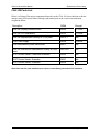
Replacement Parts Listing
CNA-100 Parts List:
Below is a listing of the major components that make up the CNA-100, the technician or theatre
manager may find it useful when ordering replacement parts in the event of an automation
component failure.
Description
OEM#
Strong#
CNA-100 Display interface board
29326
5172009
CNA-100 CPU Mainboard
39325
5172008
CNA-100 Replacement Overlay w/ Front panel
39310-1
-NA-
CNA Power supply
39328
5198304
CNA Replacement power transformer
64011
-NA-
CNA-100 Wall-Mount Replacement Overlay w/ Front
panel
39313W-1
-NA-
DPST Rocker Switch, Power and Overrides
39336
-NA-
SPDT Rocker Switch, Overrides
39337
-NA-
SPDT Rocker Switch, Overrides
39338
-NA-
Note: Other specific parts available upon request, contact Strong International for assistance.
Strong International