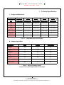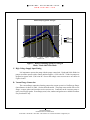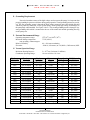
1
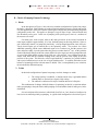
D U N I W AY
S T O C K R O O M
C O R P.
W W W . D U N I W A Y . C O M
Instruction Manual
Sputter - Ion Pump
Models V20, V30, V60, V110, V140
V220, V270, V400, V500
Copyright © 1998 by Duniway Stockroom Corp.
1 of 22
1305 SPACE PARK WAY
MOUNTAIN VIEW, CALIFORNIA 94043
TELEPHONE: 1-650-969-8811 TOLL-FREE: 1-800-446-8811 FAX: 1-650-965-0764 EMAIL: [email protected]
D U N I W AY
S T O C K R O O M
C O R P.
W W W . D U N I W A Y . C O M
Table of Contents
I Technical Specifications
A.
B.
C.
D.
E.
F.
G.
page 4
Weight and Dimensions
Pumping Speed Data
High Voltage Supply Input Rating
Vacum Flange Connection
Grounding Requirements
External Environmental Range
Vacum Operation Range
II Principle of Operation
page 7
A. Overview
B. Choice of Pumping Element Technology
C. Typical Applications
III Installation
A.
B.
C.
D.
E.
page 11
Preliminary Tests
Mounting Requirements
Grounding Requirements
Connecting the High Voltage Supply
Starting the Pump
IV Operation/Protection
page 18
A. Introduction
B. Pressure Indication
V Maintenance
A.
B.
C.
D.
E.
F.
page 20
Leakage Current & Hi-Potting
Leak Checking
Magnet Checking
Demounting the Pump
Factory Maintenance
High Voltage Feedthrough
2 of 22
1305 SPACE PARK WAY
MOUNTAIN VIEW, CALIFORNIA 94043
TELEPHONE: 1-650-969-8811 TOLL-FREE: 1-800-446-8811 FAX: 1-650-965-0764 EMAIL: [email protected]
D U N I W AY
S T O C K R O O M
C O R P.
W W W . D U N I W A Y . C O M
List of Figures
Table 1: Pump Dimensions and Weights
page 4
Table 2: Relative Pumping Speeds
Various Gases and Pump Element Technologies
page 4
Table 3: Model Number Cross Reference
page 6
Figure 1: Relative Pumping Speed for Nitrogen
Diode, Triode and Noble Diode
page 5
Figure 2: Diode Sputter-Ion Pump Configuration
(Models V20, V30, V60, V140, V270 and V500)
page 7
Figure 3: Triode Sputter-Ion Pump Configuration
(Models V110, V220, and V400)
page 9
Figure 4: Photograph of V20, V30 and V60 Ion Pumps
page 10
Figure 5: Photographs of V110/V140, V220/V270 and V400/V500
page 10
Figure 6: Feedthrough with “Garter Spring “
and Grounded Connector Shell
page 12
Figure 7: Sputter-Ion Control Unit Voltage and Power vs. Current
IPC-0062
page 17
Figure 8: Sputter-Ion Control Unit Voltage and Power vs. Current
IPC-0066
page 17
Figure 9: Sputter-Ion Pump Current vs. Pressure
V20, V30 and V60 Ion Pumps
page 19
Figure 10: Sputter - Ion Pump Current vs. Pressure
V110/140, V220/270 and V400/500 Ion Pumps
page 19
Figure 11: Magnet Orientations for Various Pump Configurations
page 21
3 of 22
1305 SPACE PARK WAY
MOUNTAIN VIEW, CALIFORNIA 94043
TELEPHONE: 1-650-969-8811 TOLL-FREE: 1-800-446-8811 FAX: 1-650-965-0764 EMAIL: [email protected]
D U N I W AY
S T O C K R O O M
C O R P.
W W W . D U N I W A Y . C O M
I Technical Specifications
A. Weight and Dimensions
Pump Speed
Flange OD
Height
Width
Depth
Weight
(l/s)
Inches (mm)
Inches (mm)
Inches (mm)
Inches (mm)
Pounds (Kg)
20
2.75 (70)
7.35 (186)
8.40 (214)
5.20 (132)
27 (12.3)
30
4.50 (114)
8.56 (218)
9.50 (242)
5.20 (132)
34 (15.4)
60
6.00 (152)
11.44 (290)
14.00 (353)
5.20 (132)
55 (25.0)
110/140
8.00 (203)
21.75 (552)
12.25 (312)
8.50 (216)
165 (75.0)
220/270
8.00 (203)
21.75 (552)
12.25 (312)
10.62 (270)
250 (113.6)
400/500
8.00 (203)
21.75 (552)
20.00 (508)
10.62 (270)
400 (181.8)
Table 1: Pump Dimensions and Weights
B. Pumping Speed Data
Gas Species
Diode
Triode
Noble Diode
Nitrogen
100
70
85
Oxygen
70
70
70
Hydrogen
220
140
160
Argon
1-2
20
20
Helium
10
20
15
Carbon Dioxide
100
70
85
Water Vapor
100
70
85
Table 2: Relative Pumping Speeds
Various Gases and Pump Element Technologies
4 of 22
1305 SPACE PARK WAY
MOUNTAIN VIEW, CALIFORNIA 94043
TELEPHONE: 1-650-969-8811 TOLL-FREE: 1-800-446-8811 FAX: 1-650-965-0764 EMAIL: [email protected]
D U N I W AY
S T O C K R O O M
C O R P.
W W W . D U N I W A Y . C O M
Relative Pumping Speeds - Nitrogen
120
80
60
Pumping Speed - l/s
100
Diode
Noble Diode
Triode
40
20
1.00E-10
1.00E-09
1.00E-08
1.00E-07
1.00E-06
1.00E-05
0
1.00E-04
Pressure - Torr
Figure 1: Relative Pumping Speed for Nitrogen
Diode, Triode and Noble Diode
C. High Voltage Supply Input Rating
It is important to operate the pump with the proper control unit. Diode and Noble Diode ion
pumps are rated to operate with a control unit that supplies +5,500 volts DC. Triode ion pumps are
designed to operate with -5,500 volts DC. Power and voltage versus current curves are shown in
Figures 6 and 7.
D. Vacum Flange Connection
The vacuum flange connection from the pump to the vacuum system is a ConFlat type flange.
Outer diameter is shown in Table 1 for the different models. The pump comes sealed with a cover
flange, a copper gasket and 6 stainless steel screw/nut sets. Connection to the vacuum system requires a new copper gasket. Extra flanges, nuts, bolts, washers and gaskets are available from Duniway Stockroom Corp..
5 of 22
1305 SPACE PARK WAY
MOUNTAIN VIEW, CALIFORNIA 94043
TELEPHONE: 1-650-969-8811 TOLL-FREE: 1-800-446-8811 FAX: 1-650-965-0764 EMAIL: [email protected]
D U N I W AY
S T O C K R O O M
C O R P.
W W W . D U N I W A Y . C O M
E. Grounding Requirements
Due to the hazardous nature of the high voltage used to operate this pump, it is important that
proper grounding be present at all times during pump operation. Dual grounding means are provided: The first grounding means is through the high voltage connector outer cable shield and shell
which are positively connected, via the “garter spring” on the pump high voltage feed through, to
the pump body when installed. See Figure 5 above. The second grounding means is through a separate grounding cable which is connected to the case of the control unit and the grounding boss/lug
on the pump case.
F. External Environmental Range
Operating temperature range:
Maximum baking temperature:
non operating, without magnet
Relative Humidity:
Elevation:
32oF (0oC) to 100oF (38oC)
775oF (450oC)
0% - 90% non-condensing
-1000 ft (-300 meters) to +10,000 ft (+3000 meters) MSL
G. Vacum Operation Range
2 x 10⁻³ torr (2 microns, 2 millitorr)
10-4 torr to below 10-11 torr
Maximum Starting Pressure:
Continuous Operating Range:
Duniway
Model #
DuniwayOrder #
Varian
Equivalent
Element
Type
Pump Speed
(Nitrogen)
DSC Control
Unit
V20D
V20T
V20N
V30D
V30T
V30N
V60D
V60T
V60N
V110T
V140D
V140N
V220T
V270D
V270N
V400T
V500D
V500N
VA-20-DD/M
VA-20-TR/M
VA-20-ND/M
VA-30-DD/M
VA-30-TR/M
VA-30-ND/M
VA-60-DD/M
VA-60-TR/M
VA-60-ND/M
VA-110-TR/M
VA-140-DD/M
VA-140-ND/M
VA-220-TR/M
VA-270-DD/M
VA-270-ND/M
VA-400-TR/M
VA-500-DD/M
VA-500-ND/M
911-5036
911-5030
911-5050
911-5037
911-5032
NA
911-5038
911-5034
NA
912-7006
912-7000
NA
912-7014
912-7008
NA
912-7022
912-7016
NA
Diode
Triode
Noble Diode
Diode
Triode
Noble Diode
Diode
Triode
Noble Diode
Triode
Diode
Noble Diode
Triode
Diode
Noble Diode
Triode
Diode
Noble Diode
20
14
17
30
21
25
60
42
50
110
140
120
220
270
230
400
500
425
IPC-0062
IPC-0062
IPC-0062
IPC-0062
IPC-0062
IPC-0062
IPC-0062
IPC-0062
IPC-0062
IPC-0066
IPC-0066
IPC-0066
IPC-0066
IPC-0066
IPC-0066
IPC-0066
IPC-0066
IPC-0066
Table 3: Model Number Cross Reference
6 of 22
1305 SPACE PARK WAY
MOUNTAIN VIEW, CALIFORNIA 94043
TELEPHONE: 1-650-969-8811 TOLL-FREE: 1-800-446-8811 FAX: 1-650-965-0764 EMAIL: [email protected]
D U N I W AY
S T O C K R O O M
C O R P.
W W W . D U N I W A Y . C O M
II
Principle of Operation
A. Overview
The sputter-ion pump operates on the principle of the Penning cold-cathode discharge. In this
type of pump, a combination of magnetic and electric fields sustains a discharge in a structure such
as shown in Figure 1. In the most common configuration, an array of cylindrical anode cells is
placed between parallel cathode plates made of titanium. A positive voltage of between 3000 volts
and 7000 volts is applied to the anode and a magnetic field of between 1000 and 2000 gauss is applied parallel to axis of the anode cells. At pressures below approximately a millitorr, a cloud of
spiralling electrons is captured inside the anode cells. These electrons collide with residual gas molecules to form positive ions. The gas molecules, being heavier and of opposite charge than the electrons, accelerate out of the anode cell toward the cathode plates. When they reach the cathode, the
ions release their energy, causing:
1. Some of the titanium atoms to be released (sputtering). This chemically active material is
deposited onto surfaces nearby. It acts as a getter until saturated.
2. Secondary electrons to be released, which get incorporated into sustaining the discharge
inside the anode cells.
3. Chemical reaction with the titanium, if the gas ion is an active, and/or burial in the cathode
for both active and noble gases.
Figure 2: Diode Sputter-Ion Pump Configuration
(Models V20, V30, V60, V140, V270 and V500)
7 of 22
1305 SPACE PARK WAY
MOUNTAIN VIEW, CALIFORNIA 94043
TELEPHONE: 1-650-969-8811 TOLL-FREE: 1-800-446-8811 FAX: 1-650-965-0764 EMAIL: [email protected]
D U N I W AY
S T O C K R O O M
C O R P.
W W W . D U N I W A Y . C O M
B. Choice of Pumping Element Technology
1. Diode
In the description of Figure 1 above the most common configuration of sputter-ion pumps,
the diode, is described. Both cathodes are made of titanium and the structure is simple and rugged.
For most applications, where active and/or residual gases comprise the main load on the pump, this
configuration works well. This applies to Nitrogen, Oxygen, Water Vapor, Carbon Dioxide and
like chemically active gases. In the case of pumping some specific gases, however, variations of
the structure are useful.
For noble gases, such as argon, either as the main gas load or as the result of sustained air
leaks (argon comprises approximately 1% of air), the diode pump can develop problems. Since argon is chemically neutral, it is pumped by burial only. After prolonged operation, some of the previously buried argon gets re-emitted due to the sputtering action. The pressure rise causes
additional sputtering, which causes additional argon to be re-emitted, etc. and the pressure rises
more and more rapidly, up to the point where the pressure reaches about 10-4 torr. At this point the
electrical discharge changes mode into a more diffuse form, the argon gets slowly pumped into other areas of the pump and the pressure slowly falls over a few minutes. At a certain point, the discharge shifts back into the confined Penning mode, and the pressure falls rapidly to the base
pressure of the system. This behavior, called “argon instability”, continues in a periodic fashion,
with a period which increases as the size of argon load decreases. To stabilize this behavior, the
balance of sputtering/burial/re-emission must be shifted. This is accomplished by two variations:
the triode and the differential pump.
2. Triode
In the triode configuration of sputter-ion pumps, two basic changes are made:
a. The voltage polarity is modified, so that the anode array is grounded and the
cathode plates are operated at a negative high voltage.
b. The cathode is constructed of strips of titanium instead of a flat plate.
This combination of changes shifts the balance of sputtering, ion burial, re-emission and net
noble gas pumping to the point where stable pumping of air and modest loads of noble gases can be
maintained.
Several variations of this structure, called triode, StarCell, etc., have been used, with more or
less success in stabilizing noble gas pumping. A typical triode configuration is shown in Figure 2.
8 of 22
1305 SPACE PARK WAY
MOUNTAIN VIEW, CALIFORNIA 94043
TELEPHONE: 1-650-969-8811 TOLL-FREE: 1-800-446-8811 FAX: 1-650-965-0764 EMAIL: [email protected]
D U N I W AY
S T O C K R O O M
C O R P.
W W W . D U N I W A Y . C O M
Figure 3: Triode Sputter-Ion Pump Configuration
(Models V110, V220, and V400)
3. Noble Diode/Differential
Another variation for stable pumping of noble gases, is called the noble diode or differential
ion pump. In this diode configuration, instead of two cathodes, both made of titanium, one of the
cathodes is made of tantalum. Tantalum is a heavier element (atomic weight 181 versus titanium
at 48), and thus sputters at a slower rate than titanium. This differential sputtering again shifts the
areas of burial and net build-up of sputtered material to an extent which results in stable pumping
of noble gases.
4. Hydrogen
The pumping of sustained loads of hydrogen requires another variation in the cathode structure of the diode configuration. Hydrogen has a high affinity for titanium, which combined with its
small diameter, causes the hydrogen to be captured and diffused into the bulk of the cathode material. In order to accommodate larger quantities of hydrogen, the cathode material is made thicker
in special hydrogen pumping elements.
C. Typical Applications
Because of their simplicity, cleanliness and trouble free operation at low pressures, sputterion pumps are especially suited for a number of applications. These include, electron beam devices,
ion beam devices, particle accelerators, high power vacuum tubes, semiconductor processing equipment, mass spectrometers, material research equipment and many others.
9 of 22
1305 SPACE PARK WAY
MOUNTAIN VIEW, CALIFORNIA 94043
TELEPHONE: 1-650-969-8811 TOLL-FREE: 1-800-446-8811 FAX: 1-650-965-0764 EMAIL: [email protected]
D U N I W AY
S T O C K R O O M
C O R P.
W W W . D U N I W A Y . C O M
Figure 4: Photograph of V20, V30 and V60 Ion Pumps
Figure 5: Photographs of V110/V140, V220/V270 and V400/V500
10 of 22
1305 SPACE PARK WAY
MOUNTAIN VIEW, CALIFORNIA 94043
TELEPHONE: 1-650-969-8811 TOLL-FREE: 1-800-446-8811 FAX: 1-650-965-0764 EMAIL: [email protected]
D U N I W AY
S T O C K R O O M
C O R P.
W W W . D U N I W A Y . C O M
III
Installation
A. Preliminary Tests
The sputter-ion pump arrives well protected in a package and under vacuum. After carefully
unpacking the pump, inspect it for signs of shipping damage. If any shipping damage is suspected,
immediately contact Duniway Stockroom Corp. Before opening the flange with the copper pinchoff, it is advisable to check to be sure that it is still under vacuum, as it was shipped. This is accomplished by properly grounding the pump case (see above), connecting the high voltage connector
and applying the operating voltage to the pump. The magnet must be in place. Normally, there will
be a brief surge of current, of less than 100 micro-amperes, due to pressure rise during shipment,
which will dissipate rapidly. Within a brief time, the current should fall to the microamp level, corresponding to pressure of less than1x10-8 torr. If a high current is observed, or if the current does
not fall rapidly to less than a few microamps, or if no current at all is observed, the pump is probably
not under vacuum. Contact Duniway Stockroom immediately.
B. Mounting Requirements
The system should have a mounting flange which is the same as the pump flange: See Table
1 for flange diameters for each pump model. A new copper gasket and the set of bolts and nuts from
the original closure flange are required. See Table 1 for pump dimensions for clearance requirements.
C. Grounding Requirements
Due to the hazardous nature of the high voltage used to operate this pump, it is important that proper grounding be present at all times during pump operation. Dual grounding means are provided: The first grounding means is through the high voltage cable shield
and connector shell which are connected to the control unit chassis and pump body when
installed. Be sure that the “garter spring” around the pump high voltage feedthrough is in
place when the high voltage connector is installed. See Figure 6 below for a view of the
high voltage feedthrough and connector shell. The second grounding means is through a
separate grounding cable which is connected to the case of the control unit and the grounding boss/lug on the pump case.
11 of 22
1305 SPACE PARK WAY
MOUNTAIN VIEW, CALIFORNIA 94043
TELEPHONE: 1-650-969-8811 TOLL-FREE: 1-800-446-8811 FAX: 1-650-965-0764 EMAIL: [email protected]
D U N I W AY
S T O C K R O O M
C O R P.
W W W . D U N I W A Y . C O M
Figure 6: Feedthrough with “Garter Spring “
and Grounded Connector Shell
D. Connecting the High Voltage Supply
Caution:
The voltages utilized by sputter-ion pumps are hazardous and can
cause severe injury or death if proper procedures are not followed.
The high voltage connection is provided via a coaxial cable, which has MS type connector on
the control unit end and a male banana plug surrounded by a ceramic insulator and grounded metal
shell on the pump end. The outer shield of the coaxial cable is grounded at both ends for safety
reasons. See Figure 5 for a sketch of the pump-end connection. When connecting the high voltage
control unit to the pump, the first step is to be sure that the high voltage control unit is OFF. Then,
firmly attach the control unit end of the cable to the control unit. Next, verify that the “garter
spring” grounding spring is in place around the groove between the insulator and metal portion of
the feedthrough. Then, slip the cylindrical connector shell over the high voltage feed through, being
sure that the male banana plug of the connector engages the female receptacle of the high voltage
feedthrough and that the cylindrical shell of the connector engages the “garter spring” for grounding
purposes. When properly engaged, the connector is firmly in place with little room for movement.
12 of 22
1305 SPACE PARK WAY
MOUNTAIN VIEW, CALIFORNIA 94043
TELEPHONE: 1-650-969-8811 TOLL-FREE: 1-800-446-8811 FAX: 1-650-965-0764 EMAIL: [email protected]
D U N I W AY
S T O C K R O O M
C O R P.
W W W . D U N I W A Y . C O M
E. Starting the Pump
1. Introduction
Sputter-ion pumps have many advantages in simplicity, cleanliness and reliability for high
and ultra-high vacuum systems. The transition from the roughing pressure to independent operation at high vacuum is referred to as “starting”. With some attention to preparation and operation
during starting, this transition can be made smoothly and with a minimum of problems.
2. Preparation
Before beginning the operation of a sputter ion pump, it is advisable to consider some system
and safety issues. If these issues are taken into account, both personal and equipment convenience
will be assured. First of all, in order to take maximum advantage of the pumping speed available
from the sputter-ion pump, the conductance, or access for gas flow should be maximized. This
means decreasing the length and increasing the diameter of the tubing connecting the sputter-ion
pump to the system.
Second, cleanliness should be observed in handling and preparing both the system and the
sputter-ion pump. Exposure to oils, water vapor or dust can significantly add to the gas load, both
during starting and continued operation. Even fingerprints can be harmful in contributing to gas
loads. Sputter-ion pumps do not deteriorate just by being stored at atmospheric pressure, if they are
kept clean. Aluminum foil or a plastic cover on the inlet flange during storage will keep out dust,
dirt and debris.
Finally, for personal safety, always establish a definite electrical grounding connection from
the sputter-pump case to control unit ground. Sputter-ion pumps operate with high voltages and
current levels which can be fatal if accidental contact is made. By assuring proper grounding of the
pump, personal safety is greatly improved, and proper operation of control unit overload circuits is
provided.
3. Control Unit/Power Supply
Each sputter-ion pump requires a control unit of an appropriate voltage level, polarity and
current capacity. These parameters are best determined by consulting the User Manual for the sputter-ion pump and/or the control unit. If the original documents are not available, the manufacturer’s
catalog may have the information. In any case, you can call Duniway Stockroom, where a comprehensive listing of this information is maintained. (“Varian and Perkin Elmer Ion Pump Control
Units, 1961-1992, 1992-1996.”)
In general, the larger the pump rating in liters per second, the higher the required current capacity. Also, triode configurations (triode or StarCell) require negative voltage polarity while diode
configurations (diode, noble diode, DI) require positive voltage polarity.
13 of 22
1305 SPACE PARK WAY
MOUNTAIN VIEW, CALIFORNIA 94043
TELEPHONE: 1-650-969-8811 TOLL-FREE: 1-800-446-8811 FAX: 1-650-965-0764 EMAIL: [email protected]
D U N I W AY
S T O C K R O O M
C O R P.
W W W . D U N I W A Y . C O M
Voltage is usually rated as “open circuit voltage”, that is the voltage with no current load on
the control unit. Current is usually rated as “short circuit current”, that is the current drawn by the
power supply when the output is shorted to ground.
Examples of voltage and power versus current for typical sputter-ion pump control units are
shown below in Figures 7 and 8. A Duniway Stockroom Corporation IPC-0062 for pump models
V20. V30 and V60, is shown in Figure 7 and the Duniway Stockroom Corporation IPC-0066 for
pump models V110/140, V220/270 and V400/500 is shown in Figure 8.
In the plots in Figure 7 and 8, the voltage is represented on the vertical axis by the bars, the
power is represented on the vertical axis by the line plot and the current is represented on the horizontal axis. The voltage rating of the power supply is shown by the maximum voltage plot at the
upper left of the graph, or approximately 5,300 volts for the IPC-0062 in Figure 7; the current rating
of the power supply is shown by the point in the lower right of the plot where the power curve intercepts the lower axis, or 0.17 amps (170 ma) for the IPC-0062; and the power rating is shown by
the top of the power curve, or 220 watts for the IPC-0062.
The equivalent ratings for the IPC-0066 can be seen in Figure 8.
The product of voltage and current at any point in the process gives the power going into the
sputter-ion pump. This information is displayed as plot of power versus current. This plot has a
power maximum near the middle range of the current capacity. This maximum is called the “power
hill”, because as the pump current moves either up or down (the same as the pressure moving up or
down) it must climb this “power hill”. Increasing power means increasing heat to be dissipated,
which normally means an increasing gas load due to outgassing. As we will see below (5. Starting),
the heating that takes place due to power dissipation has an effect on the starting of the pump.
Sputter-ion pump current is proportional to pressure, especially in the pressure ranges below
10 torr. This relationship is expressed by the equation: I/P=constant. Thus, at lower pressures,
pump current can be used as an indicator of the pressure. An example of the relationship between
sputter-ion pump current and pressure is shown attached as Figure 9; in this case for diode pumps
of 20, 30 and 60 liters per second; the control unit is a Duniway Stockroom IPC-0062. The slope
of the I/P curve for the 30 l/s pump shown is 500 amps per torr. (Calculated by choosing a typical
point on the curve, say 1 milliamp at 2x10⁻⁶ torr, and dividing the current at that point by the pressure at that point).
-5
The I vs. P relationship for pumps with speeds of 110/140 l/s, 220/270 l/s, and 400/500 l/s is
shown in Figure 10.
14 of 22
1305 SPACE PARK WAY
MOUNTAIN VIEW, CALIFORNIA 94043
TELEPHONE: 1-650-969-8811 TOLL-FREE: 1-800-446-8811 FAX: 1-650-965-0764 EMAIL: [email protected]
D U N I W AY
S T O C K R O O M
C O R P.
W W W . D U N I W A Y . C O M
4. Roughing/Trapping
Sputter-ion pumps operate by using a low pressure gas discharge called the Penning discharge. Through a combination of magnetic field and electric field, gas ions are formed and captured on active metal plates, such as titanium. The Penning discharge only operates at pressures
below approximately 10-3 torr, so the pressure in the pump and vacuum system must be reduced by
other means to reach that pressure range.
A variety of rough vacuum pumps is available, including rotary mechanical pumps, turbomolecular pumps and sorption pumps. Since the sputter-ion pump is inherently clean and typically
used in clean, ultra-high vacuum applications, it is important to use a clean technique for rough
pumping. Also, the roughing pump should have a valve to isolate it from the sputter-ion pump after
the starting phase, since the sputter-ion pump can operate independently on a closed system. In addition to the gases contained in the volume of the system, the main gas load at the lower pressures
is represented by the water vapor that is adsorbed on all the surfaces of the system.
It is a good idea to check the base pressure obtained by the roughing pump to assure that the
pump is reaching a pressure adequately low for sputter-ion pump starting. A properly calibrated
thermocouple gauge will do the job, and a pressure below 10 millitorr indicates adequate roughing
pump performance. Lower pressure before starting will generally lead to quicker results.
The cleanest roughing pump technology is the sorption pump, which uses ultra-high surface
area materials such as molecular sieve, which are chilled to liquid nitrogen temperatures. Water
vapor, oxygen, nitrogen, argon and most organic vapors are pumped by sorption pumps, thus reducing the pressure to a few millitorr. For small systems a single stage sorption pump is sufficient to
reach the starting pressure for sputter-ion pumps; for larger systems a sequenced, two stage sorption
pump is recommended. Prior to using a sorption pump, it is important to remove the previously
absorbed gases, particularly water vapor, by baking the pump.
Rotary mechanical pumps, which use oil-sealed vanes, can also be used for rough pumping;
however, an efficient trap must be provided between the mechanical pump and the sputter-ion
pump. Either a liquid nitrogen trap or a molecular sieve trap can be used to keep the mechanical
pump oil from migrating into the sputter-ion pumped system. In addition, the trap will help remove
water vapor, the major gas load during the later stages of rough pumping. Mechanical pumps are
not efficient at removing water vapor, since it just gets recycled through the oil on each rotation of
the pump rotor.
Another good alternative for rough pumping is the turbomolecular pump. This pumping
technology is clean and provides a better pumping speed and lower roughing pressure than other
alternatives.
15 of 22
1305 SPACE PARK WAY
MOUNTAIN VIEW, CALIFORNIA 94043
TELEPHONE: 1-650-969-8811 TOLL-FREE: 1-800-446-8811 FAX: 1-650-965-0764 EMAIL: [email protected]
D U N I W AY
S T O C K R O O M
C O R P.
W W W . D U N I W A Y . C O M
5. Starting
When the roughing pressure falls below 10 millitorr, the sputter-ion starting process can begin. To review the precautions, be sure that the pump is properly grounded, that the control unit
voltage polarity and power rating are matched to the pump being started.
Verify that the control unit “Start-Protect” switch is set to the “Start” position, and that the
“Meter Range” switch is set to “Voltage”. Now turn on the “Power” switch. Immediately after
turning on the power switch, observe the voltage reading on the meter. In the starting mode, the
voltage should be in the 300-1000 volt range, and then gradually rise as the pump starts. (If the
voltage reading is either at zero or at the open circuit rating of the control unit when the pump is
turned on during starting, immediately turn the control unit off, because there is either an electrical
short in the pump or an open circuit which must be found and corrected before proceeding.)
Next, turn the meter switch to the highest current scale and verify that the current is near the
appropriate (near short circuit current) for the control unit. Return the meter range switch to the
“Voltage” position to monitor the operation of the pump. When it appears that the roughing system
has reached its base pressure, close the valve between the roughing system and the sputter-ion pump
and observe the results on the “Voltage” scale of the control unit. If the voltage falls, indicating a
rising current (rising pressure), reopen the roughing valve. If the voltage increases or remains the
same, leave the roughing valve closed.
NOTE:
With a sputter-ion pump, a modest rise in pressure is normal during the initial starting phase. This is caused by heating of the pump components by
the dissipated power and normally precedes operation in the normal mode.
Some heating during starting is beneficial because it causes out-gassing of
components which will not have to take place during later stages of the system pump down. Excessive heating due to prolonged high pressure operation or a mismatched control unit can damage a pump. Operation in the start
mode should always be monitored. The electrical discharge in a sputter-ion
pump gives off a blue/purple glow due to the electron-gas ionization process
taking place. At starting pressures, above 10-4 torr, the discharge occurs
throughout the pump; in some cases it can extend into the system itself. If
the presence of this discharge in the system is a problem, a stainless steel,
electrically grounded screen can be placed across the mouth of the pump. As
the sputter-ion pump starts, the discharge confines itself to the area within
the pump elements, and gradually becomes fainter as the pressure, and thus
the rate of ionization, falls.
16 of 22
1305 SPACE PARK WAY
MOUNTAIN VIEW, CALIFORNIA 94043
TELEPHONE: 1-650-969-8811 TOLL-FREE: 1-800-446-8811 FAX: 1-650-965-0764 EMAIL: [email protected]
D U N I W AY
S T O C K R O O M
C O R P.
W W W . D U N I W A Y . C O M
Voltage & Power vs. Current
6000
Voltage - Volts
250
Power -Watts
200
4000
150
Voltage
Power
100
2000
50
0
0
0
20
30
50
70
80
100 120 130 150 170 180 200
Current
Figure 7: Sputter-Ion Control Unit Voltage and Power vs. Current
IPC-0062
IP C -0 0 6 6 T rio d e P o w e r/Vo lta g e v s .
C u rre n t (A mp s )
6000
800
700
5000
600
4000
500
3000
400
V oltage (V olts )
P ower (W atts )
300
2000
200
1000
100
0
0
0
0.1
0.2
0.3
0.4
0.5
0.6
0.7
0.8
Figure 8: Sputter-Ion Control Unit Voltage and Power vs. Current
IPC-0066
17 of 22
1305 SPACE PARK WAY
MOUNTAIN VIEW, CALIFORNIA 94043
TELEPHONE: 1-650-969-8811 TOLL-FREE: 1-800-446-8811 FAX: 1-650-965-0764 EMAIL: [email protected]
D U N I W AY
S T O C K R O O M
C O R P.
W W W . D U N I W A Y . C O M
IV
Operation/Protection
A. Introduction
After the sputter-ion pump starts, as indicated by the voltage rising toward the open-circuit
rating and current falling to below about 25% of the rated value on the control unit meter, normal
operation can commence.
In normal operation, the roughing pump valve is closed and the “Start/Protect” switch on the
control unit is placed in the “Protect” position. The pump is now protected against a pressure rise
above approximately 0.5 mTorr while unattended. Should such a pressure rise occur due to a leak
or other failure, the control unit will automatically turn off after a brief delay. This protects both
the pump and control unit against excessive current and heat conditions.
During normal operation, pump current is proportional to pressure over a wide operating
range. This is illustrated in the typical current vs. pressure curves shown below in Figures 9 and
10. By knowing the current and using the correct curve for that pump and control unit, the pressure
can be calculated. In addition, most control units have a “Pressure” scale, which is a logarithmic
scale from below 10-9 torr to above 10-4 torr. Also, a recorder and control signal, with a range from
0 to 100 mV, is normally available for monitoring the pump pressure.
B. Pressure Indication
As discussed above, sputter-ion pump current is proportional to pressure over the operating
range. The graphs in Figures 9 and 10 below show typical plots of Ion Pump Current vs. Pressure
for a variety of pump sizes. For example, for a 30 liter per second pump with a current indication
of 1 ma, the pressure would be about 2x10⁻⁶ torr. Caution should be used in using ion pump current
to indicate pressure, especially at low pressures, due to potential leakage current, as discussed below
in “Maintenance”.
18 of 22
1305 SPACE PARK WAY
MOUNTAIN VIEW, CALIFORNIA 94043
TELEPHONE: 1-650-969-8811 TOLL-FREE: 1-800-446-8811 FAX: 1-650-965-0764 EMAIL: [email protected]
D U N I W AY
S T O C K R O O M
C O R P.
W W W . D U N I W A Y . C O M
Ion Pump Current vs. Pressure
Pressure - Torr
1.00E-09 1.00E-08 1.00E-07 1.00E-06 1.00E-05 1.00E-04
8 l/s
100
20 l/s
10
30 l/s
60 l/s
0.1
0.01
0.001
0.0001
Current - Amps
1
Figure 9: Sputter-Ion Pump Current vs. Pressure
V20, V30 and V60 Ion Pumps
Ion Pump Current vs. Pressure
Pressure - Torr
1.00E-09 1.00E-08 1.00E-07 1.00E-06 1.00E-05 1.00E-04
1000
400/500 l/s
220/270 l/s
100
110/140 l/s
1
0.1
Current - mA
10
0.01
Figure 10: Sputter - Ion Pump Current vs. Pressure
V110/140, V220/270 and V400/500 Ion Pumps
19 of 22
1305 SPACE PARK WAY
MOUNTAIN VIEW, CALIFORNIA 94043
TELEPHONE: 1-650-969-8811 TOLL-FREE: 1-800-446-8811 FAX: 1-650-965-0764 EMAIL: [email protected]
D U N I W AY
S T O C K R O O M
C O R P.
W W W . D U N I W A Y . C O M
V
Maintenance
A. Leakage Current & Hi-Potting
After prolonged operation, which generates quantities of sputtered material inside the pump,
it is possible that current leakage, not related to pump pressure, may develop in the pump. There
are two types of leakage: “Resistive Leakage” and “Field Emission Leakage”. (In both cases, such
leakage can be confirmed by removing the pump magnets, which should not substantially change
the leakage current.)
Resistive Leakage is due to resistive coatings or short circuits of insulating elements in the
pump. The presence of this leakage can be detected by using a simple ohm-meter or multi meter
on the ohm or resistance scale. When resistive leakage occurs, pumping action is usually reduced
or stopped, and the pump or pump elements must be rebuilt. See Section IV-E below for factory
maintenance.
Field Emission Leakage is due to electron release from small points or flakes in the pump, at
the high voltages inside the pump. This problem does not effect the pumping action of the pump,
however it may be annoying if the pump current is used as an indication of the pressure in the system. In order to reduce or eliminate field emission leakage, it is possible to apply an over voltage,
a process known as “hi-potting”. Since field emission current grows exponentially with voltage,
the application of higher than normal voltage can cause enough current to flow to melt the sharp
points and reduce the leakage to an acceptable level. A Hi-Pot unit with voltages of 12-15 KV AC
at a few milliamps is usually adequate to reduce the field emission leakage to an acceptable level.
For more information on this procedure, call Duniway Stockroom Corporation.
CAUTION:
Extreme caution must be excersized when performing such an operation due
to the hazardous nature of the voltages involved. Proper insulation and
grounding must be supplied in order to avoid injury to personnel and damage to equipment.
B. Leak Checking
If prolonged operation, especially after baking of the system, does not result in appropriately
low pressures, it is possible that there is a leak in the system. Some level of leak checking can be
performed by observing the ion pump current while probing the exterior of the system with a probe
gas such as helium. When the probe gas enters the system through a leak, it will cause a pump current fluctuation, related to the difference in leak rate for different diameter atoms and the difference
in ionization potential of the probe gas in the ion pump discharge. More sensitivity may be obtained
by using a strip chart recorder or computer display to record the pump current.
20 of 22
1305 SPACE PARK WAY
MOUNTAIN VIEW, CALIFORNIA 94043
TELEPHONE: 1-650-969-8811 TOLL-FREE: 1-800-446-8811 FAX: 1-650-965-0764 EMAIL: [email protected]
D U N I W AY
S T O C K R O O M
C O R P.
W W W . D U N I W A Y . C O M
C. Magnet Checking
If the sputter ion pump does not seem to be operating with its normal pumping speed, it is
possible that there may be a problem with magnet field strength or magnet installation. The following illustration shows proper magnet installation for a variety of pump configurations. Following
the illustration is a discussion of procedures for checking magnet installation.
Figure 11: Magnet Orientations for Various Pump Configurations
1. All magnets, including the Earth, have a North pole and a South pole. A simple compass
can be used to determine the polarity of a magnet segment, however, readings should be
made away from iron pole pieces.
2. Like poles (N-N or S-S) repel each other and unlike poles (N-S or S-N) attract each other.
3. In an Ion Pump magnet array, the magnet sections must be arranged in a magnetic circuit;
that is N-S-N-S-N-S…etc., all the way around the pump.
4. The magnetic field should be between 1000-1500 gauss for most Sputter-Ion pumps. Higher
magnetic fields give somewhat higher pumping speed, especially at low pressure.
5. When assembling an Ion Pump magnet array, the magnets will tend to ‘pull’ into a correct
circuit configuration and ‘push’ out of an incorrect circuit configuration.
6. In Figure 11, Example 1, (a cross section of a pump such as the VPE20 and V30 models), as
long as the individual blocks on the magnet assembly are installed correctly, the orientation
of the magnet assembly does not matter.
21 of 22
1305 SPACE PARK WAY
MOUNTAIN VIEW, CALIFORNIA 94043
TELEPHONE: 1-650-969-8811 TOLL-FREE: 1-800-446-8811 FAX: 1-650-965-0764 EMAIL: [email protected]
D U N I W AY
S T O C K R O O M
C O R P.
W W W . D U N I W A Y . C O M
7. In Figure 11, Example 2, (a cross section of a pump such as the V60, V110/140 and V400/
500Varian 60 l/s models), as long as the individual blocks on the magnet assembly are
installed correctly, the orientation of the magnet assembly does not matter.
8. In Figure 11, Example 3, (a cross section of a pump such as a V400/500Varian 110 or 140 l/
s models), the circuit must be completed exactly as shown. If one of the magnet assemblies
is installed backwards, the pump will operate with some reduction in speed, but the stray
magnetic field will be excessively high, and may interfere with sensitive experiments.
D. Demounting the Pump
If for any reason, it becomes necessary to remove the pump from the system, be sure to take
the proper precautions for personnel and equipment safety. First of all, turn the control unit to the
off condition. Then, remove the high voltage connector from the pump. At this point it is a good
idea to remove the magnet from the pump to reduce the weight of the pump assemble. Then make
sure that the pump is properly supported before starting to remove the bolts from the connection
flange. Also, it is not a good idea to let the system up to atmospheric pressure by removing the sputter-ion pump, because any loose material around the gasket may be swept into the system. Loosen
slightly all the bolt/nut combinations before completely removing any of the bolts.
E. Factory Maintenance
If it should become necessary to perform maintenance on the pump, such as replacing the
pumping elements or high voltage feedthrough, it is best to return the pump, without its magnets,
to the factory for maintenance. Please call Duniway Stockroom Corporation for advice and details
about sputter-ion pump maintenance and rebuilding.
F. High Voltage Feedthrough
The high voltage feedthrough is mounted on a mini ConFlat flange. If the feedthrough is
damaged or develops leakage current during transportation, installation or prolonged use, it can be
replaced in the field. Feedthroughs, gaskets and nut/bolt sets are available from Duniway Stockroom Corp.
REV. 08/07/98 GD
22 of 22
1305 SPACE PARK WAY
MOUNTAIN VIEW, CALIFORNIA 94043
TELEPHONE: 1-650-969-8811 TOLL-FREE: 1-800-446-8811 FAX: 1-650-965-0764 EMAIL: [email protected]