1
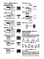
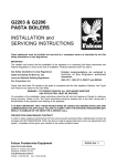
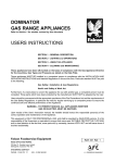
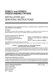
GAS CHIEFTAIN
HEAVY DUTY APPLIANCES
USERS INSTRUCTIONS
SECTION 1 - GENERAL DESCRIPTION
SECTION 2 - LIGHTING and OPERATIONS
SECTION 3 - COOKING HINTS
SECTION 4 - CLEANING and MAINTENANCE
These Appliances have been CE-marked on the basis of compliance with the Gas Appliance Directive
for the Countries, Gas Types and Pressures as stated on the Data Plate.
These Appliances MUST BE installed by a competent person in compliance with the INSTALLATION AND
SERVICING INSTRUCTIONS and National Regulations in force at the time. Particular attention MUST be paid
to the following:
Gas Safety (Installation & Use) Regulations
Health and Safety at Work Act
Furthermore, if a need arises to convert the Appliance for use with another gas, a competent person must be
consulted. Those parts which have been protected by the manufacturer MUST NOT be adjusted by the User.
Users should be conversant with the appropriate provisions of the Fire Precautions Act and the requirements of
the Gas Safety Regulations. in particular the need for regular servicing by a competent person to ensure the
continued safe and efficient performance of the Appliance.
WARNING - TO PREVENT SHOCKS, ALL APPLIANCES WHETHER
GAS OR ELECTRIC, MUST BE EARTHED
Upon receipt of the User's Instruction manual, the installer should instruct the responsible person(s) of the
correct operation and maintenance of the Appliance.
This equipment is ONLY FOR PROFESSIONAL USE, and shall be operated by QUALIFIED persons. It is the
responsibility of the Supervisor or equivalent to ensure that users wear SUITABLE PROTECTIVE CLOTHING
and to draw attention to the fact that, some parts will, by necessity, become VERY HOT and will cause burns if
touched accidentally.
Falcon Foodservice Equipment
HEAD OFFICE AND WORKS
PO Box 37, Foundry Loan, Larbert.
Stirlingshire. Scotland. FK5 4PL
AFE SERVICE CONTACT PHONE - 01438 363 000
FAX - 01438 369 900
RZZ 293 Ref. 1
SECTION 1 - GENERAL DESCRIPTION
1.1 Control Knob Details
G1006X Open Top Range
Piezo
Unit
(Inside)
Open Top Taps
Oven Flame Failure
Gas Control
Oven Flame
Failure
Gas Control
Piezo Unit
(Inside)
Oven
Thermostat
Oven Thermostat
Bottom Front Panel
G1006X Solid Top Range
Piezo
Unit
(Inside)
G1016 Single Tier Oven
Bottom Front
Panel
G1016/2 Double Tier Oven
Solid Top Tap
Oven Flame Failure
Gas Control
Oven Flame
Failure Gas
Control
Oven Thermostat
Bottom Front Panel
Piezo Unit
(Inside)
Oven
Thermostat
G1006X Twin Bullseye Range
Piezo
Unit
(Inside)
Solid Top Taps
Oven Flame Failure
Gas Control
Bottom Front
Panel
G1029X Two Burner Spreader
Oven Thermostat
Open Top
Taps
Bottom Front Panel
G1066X Open Top Range
Piezo
Unit
(Inside)
Open Top Taps
Oven Flame Failure
Gas Control
Oven Thermostat
Bottom Front Panel
G1026X Open Top Boiling Table
Open Top Taps
G1026X Solid Top Boiling Table
SECTION 2 LIGHTING AND OPERATIONS
LIGHTING THE BURNER
2.1 Open Top Burners
All taps incorporate a flame failure facility.
The burners are of equal power and the tap which
controls a specific burner is identified by the icon
adjacent to the tap. See Figures 1 and 2.
Rear Left
Open Top
Taps
Front Right
Rear Right
Figure 1 - G1006X Open Top
Solid Top
Flame Failure
Gas Tap
G1060 Open Top Boiling Table
Front Left
Rear
Left
Front
Left
Rear
Centre
Front
Centre
Front
Right
Figure 2 - G1066X Open Top
To Light A Burner
Rear
Right
Turn the control knob to the full flame position. Push
knob in fully and apply a lit taper to the burner.
Continue to hold the knob in for 20 seconds before
release. Observe that the burner remains alight.
If the burner fails to light, wait 3 minutes and repeat.
To Extinguish The Burner
Turn the tap fully clockwise to the OFF position.
LH Knob
Figure 3
2.2 SOLID HOTPLATE
RH Knob
The single solid hotplate is composed of two filling
plates, one rings and one centre bullseye. A radial
burner is located centrally below the hotplate. This is
operated by the related control knob. See Figure 3 to
identify tap markings.
The two hotplate version has four filling plates, two
rings and two centre bullseyes. A radial burner is
located centrally below each hotplate and is operated
by the related control knob. See Figure 3 to identify
tap markings.
Warning
If the burner is extinguished intentionally or
otherwise, NO attempt to re-light the gas should be
made until at least 3 minutes have elapsed.
The procedure for lighting a burner, is as follows
(Refer to Figure 3) 1. Remove the centre bullseye using the special tool
provided.
2. Have a lit taper or match ready in one hand.
3. With the other hand, push the control knob in and
turn it anti-clockwise until the knob mark is aligned
with the ignition symbol.
4. Apply the taper or match to the pilot, keep the knob
pushed in.
5. Release the knob after approximately 20 seconds.
The pilot should remain alight. If not, push in the
control knob and turn it clockwise to the off
position. Wait 3 minutes, then repeat form Step 2.
6. Having established the pilot flame, replace the
centre bullseye.
7. Turn knob anti-clockwise to the full flame symbol.
8. If desired, the burner can be turned down to the
low or simmer setting by turning the knob fully
anti-clockwise to the low flame symbol.
To Turn the Burner OFF
9. To turn a burner down but leaving it lit, turn the
knob to the ignition symbol.
10. To extinguish a burner, push the knob in and turn
to the off position.
Note
Most turning movements of the knob have to be
preceded by pushing it in.
Using the Solid Hotplate
Getting the best out of this type of heat source is
largely a matter of experience coupled with the
requirements of the task in hand. For certain
applications such as heating a pot quickly, it is
expedient to remove the centre ring and place the pot
directly over the burner. If it is necessary to heat the
entire surface, the ring must be in position.
In the interests of economy, it is recommended that
the unit should not be left unattended on full setting.
If it is necessary to keep the hob area hot for any
length of time, the control should be set to low.
Never leave the gas on without a pot when the centre
ring has been removed as such practice wastes
energy. The hottest area of the plate is the centre of
the bullseye and toward the rear. The front and sides
are cooler.
2.4 SOLID HOTPLATE
The single solid hotplate is composed of two filling
plates, a ring and a centre bullseyes. The burner is
located directly below the centre ring and is operated
by the related control knobs. See Figure 4 to identify
the tap icons.
Warning
Figure 4
Should the burner become extinguished intentionally
or otherwise, NO attempt to relight it should be made
until at least 3 minutes have elapsed.
The procedure for lighting a burner, is as follows
(Refer to Figure 4) 1. Remove the centre bullseye using the special tool
provided.
2. Have a lit taper or match ready in one hand.
3. With the other hand, push in the control knob and
turn it anti-clockwise till the knob mark is opposite
the ignition symbol.
4. Apply the taper or match to the pilot while keeping
the knob pushed in.
5. Release the knob after approximately 20 seconds.
The pilot should remain alight. If not, push the
knob in and turn it clockwise to the off position.
Wait 3 minutes, then repeat form Step 2.
6. Having established the pilot flame, replace the
centre bullseye.
7. Turn the knob anti-clockwise to the full flame
symbol.
8. If desired, the burner can be turned down to the
low or simmer setting by turning the knob fully
anti-clockwise to the low flame symbol.
To Turn the Burner OFF
9. To turn a burner down whilst leaving it lit, turn the
knob to the ignition symbol.
10.To extinguish a burner, push the knob in and turn it
to the OFF position.
2.3 OVEN
The oven controls are located on the RH side of the
unit. These consist of a thermostat and a
multi-purpose gas cock/flame supervision control.
A piezo igniter is located behind the bottom hinged
panel to ignite the pilot burner. See Figure 3 to
identify the gas tap icons.
Warning
If the pilot burner is extinguished either intentionally
or otherwise, no attempt to re-light the gas should be
made until at least 3 minutes have elapsed.
The procedure for lighting the burner is as follows:
(Refer to Figure 4)
1. Lower the bottom front panel and turn the
thermostat knob to 277oC.
2. Push the tap in and turn it anti-clockwise to the
ignition position.
3. Holding the tap fully in, press the igniter button and
observe that the pilot lights. If it does not light,
repeatedly press the igniter button until it does.
4. When the burner is lit, continue to hold the tap fully
in for 20 seconds then release it. If the burner
goes out, push in the control knob and turn it
clockwise to the off position. Wait for 3 minutes,
then repeat from (1).
5. When the burner is established, turn the tap
anti-clockwise to the full flame position. (large
symbol), thus lighting the burner.
6. Close the bottom front panel and turn the
thermostat knob to the setting required.
7. For low flame or simmer position, push in the tap
and turn it anti-clockwise to the low flame position
(small flame symbol). This setting gives an
economy control on the oven burner.
To Turn the burner OFF
8. To turn down the oven burner to ignition rate, turn
the knob to the ignition symbol position.
9. To turn off the main burner and pilot, push in the
knob and turn it to the OFF position. Turn the
thermostat knob to the OFF position also.
Using the Oven
The oven temperature is controlled automatically by a
thermostat. Leave the burner tap full on during the
period the oven is in use. The following cooking
charts give basic temperatures and times required
but for best performance the following instructions
should be carried out.
Shelves
2 shelves are supplied with the unit which can be
supported in any of four different positions within the
oven. When 2 shelves are used these should be
positioned with at least one shelf space left between
them (i.e. top and 3rd top or second top and bottom
positions). Always push the shelves all the way to the
oven rear and ensure they are inserted correctly,
i.e. shelf stops at the rear pointing upwards.
Tray Size
Tray sizes up to a maximum of 650 mm x 530 mm
can be used. Smaller trays should be placed centrally
on the shelves.
The oven accommodates 2/1 gastronorm trays.
Pre-heat Time
Allow at least 45 minutes to heat the oven up from
cold before loading with food.
Put the food in quickly to minimise heat loss and close
the door firmly after insertion.
SECTION 3 - COOKING HINTS
3.1 Small cakes, scones etc,
When preparing two trays, the upper tray will be
cooked first. It should then be removed from the oven
and the lower tray raised to the upper position.
3.2 Yorkshire Puddings etc, in baking tins
When cooking on two shelves, the upper and lower
tins should be interchanged half-way through the
cooking process.
3.3 Fruit cakes in large tins
Cooking time will vary considerably according to
weight, richness and depth of mixture. When cooking
on 2 shelves, tins should be interchanged halfway
through the cooking process.
Approximate centre oven temperatures are indicated
in the following table:
oC
125 - 150
175
200 - 225
250
275
Condition
Slow
Moderate
Fairly Hot
Hot
Very Hot
Cooking Charts
Temp. Shelf
Time
Setting Position
Fruit Pies
225
3 for 35 to 45 mins
Plate Tart
225 single
tray, 30 to 40 mins
Puff & Rough
2 & 4 15 to 25 mins
Puff Tarts
250
for
Sausage
two
Rolls
250
trays. 20 to 25 mins
Scones
260
10 to 15 mins
PASTRY
PUDDINGS
Custard
Milk
Yorkshire
Pudding
Temp. Shelf
Time
Setting Position
165
40 to 60 mins
150
45 to 90 mins
240
33 to 40 mins
Temp. Shelf
CAKES
Time
Setting Position
Slab Cake
(Rich)
150
3 hours
3 for
1
single
1 /2" Slab
Sponge
200
tray, 25 to 35 mins
Queen
2&4
Cakes
200
for 20 to 25 mins
two
Sponge
trays. 20 to 25 mins
Sandwich
200
Very Rich
Cake(Xmas) 150
3 2 to 21/2 hours
Bread
as Slab
Rolls
250
Cake 15 to 25 mins
SECTION 4 - CLEANING AND MAINTENANCE
It is advised that the unit be cleaned daily after use.
This should be carried out using hot soapy water,
ensuring that it be thoroughly rinsed and dried after
any such cleaning. Grease should be removed with
nylon or scotch cleaning pads. Take care, especially
when these are new as they may cause scratching.
A smooth-bladed metal scraper is handy to remove
deposits of burned-on grease from hob fillings.
Before removing any of the parts described below,
note how they are arranged and replace in the same
position.
4.1 OPEN HOTPLATES
Pan supports, burners and spillage trays can be
easily removed for cleaning. After washing, dry the
burners thoroughly and remove any excess water
from inside. The burners are interchangeable.
Ensure that burner caps are located correctly.
Pan Supports
Clean with warm soapy water. Abrasives such as
fine steel wool, proprietary cleaning pads and nylon
pan scrubbers should only be used in cases of
extreme overspill with care.
Dry pan supports thoroughly by hand.
NEVER LEAVE TO DRY NATURALLY.
After drying, apply a light film of vegetable oil to the
supports to prevent oxidation.
4.2 SOLID HOTPLATES
Plates can be removed for cleaning access. Having
gained access, clear accumulated debris which may
have gathered in the burner tray, particularly that
which has gathered at the hotplate support edges.
Warning
The castings are very heavy and care should be
taken during handling of such components.
4.3 OVEN
The oven linings are stainless steel and can be
cleaned easily. Wipe down with a soapy cloth while
the oven is still warm.
Shelf runners can be removed as follows Lift upward and pull the bottom edge toward the
oven centre before dropping the runner. To replace
a runner, ensure that the long leg is at the top.
Replace the shelves correctly.
Base linings can be removed by lifting the rear lining
slightly and pulling out the base panels.
Cleaning Note
Important
Never clean with a jet of water or steam clean.