1
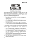
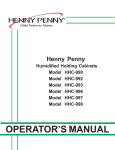
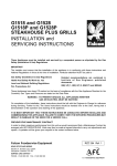
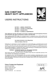
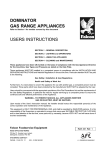
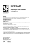
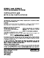
G350/11 and G350/12
FREESTANDING FRYERS
INSTALLATION and
SERVICING INSTRUCTIONS
These Appliances must be installed and serviced by a competent person as stipulated by the Gas
Safety (Installation & Use) Regulations.
IMPORTANT
The installer must ensure that the installation of the appliance is in conformity with these instructions and
National Regulations in force at the time of installation. Particular attention MUST be paid to -
Gas Safety ( Installation & Use ) Regulations
Health And Safety At Work etc. Act
Local and National Building Regulations
Fire Precautions Act
Detailed recommendations are contained in
Institute of Gas Engineers published
documents :
IGE/ UP/ 1, IGE/ UP/ 2, BS6173 and BS5440
These Appliances have been CE-marked on the basis of
compliance with the Gas Appliance Directive for the Countries, Gas Types and Pressures as stated on the
Data Plate.
WARNING - TO PREVENT SHOCKS, ALL APPLIANCES WHETHER
GAS OR ELECTRIC, MUST BE EARTHED
On completion of the installation, these instructions should be left with the Engineer-in-Charge for reference
during servicing. Further to this, The Users Instructions should be handed over to the User, having had a
demonstration of the operation and cleaning of the appliance. Particular emphasis should be made with regard
to safe operation of the drain valve.
IT IS MOST IMPORTANT THAT THESE INSTRUCTIONS BE CONSULTED BEFORE INSTALLING AND
COMMISSIONING THIS APPLIANCE. FAILURE TO COMPLY WITH THE SPECIFIED PROCEDURES MAY
RESULT IN DAMAGE OR THE NEED FOR A SERVICE CALL.
PREVENTATIVE MAINTENANCE CONTRACT
In order to obtain maximum performance from this unit we would recommend that a Maintenance Contract be
arranged with FALCON SERVICE LINE. Visits may then be made at agreed intervals to carry out adjustments
and repairs. A quotation will be given upon request to the FALCON SERVICE LINE contact numbers below.
Falcon Catering Equipment
HEAD OFFICE AND WORKS
PO Box 37, Foundry Loan, Larbert.
Stirlingshire. Scotland. FK5 4PL
SERVICE LINE CONTACT PHONE - 01438 751111
FAX - 01438 369900
RZZ 76 Ref.1
SECTION 1 - INSTALLATION
UNLESS OTHERWISE STATED, PARTS WHICH HAVE BEEN PROTECTED BY THE MANUFACTURER
ARE NOT TO BE ADJUSTED BY THE INSTALLER
Adequate ventilation, whether natural or mechanical,
1.1 MODEL NUMBERS, NETT WEIGHTS
must be provided to ensure sufficient fresh air for
and DIMENSIONS
combustion and for removal of combustion products,
DEPTH HEIGHT WEIGHT WEIGHT which may be harmful to health. Recommendations
MODEL WIDTH
mm
mm
mm
kg
lbs
for ventilation for Catering Appliances are given in
Further, to ensure sufficient room ventiG350/11
350 650 870 46 102 BS.5440:2.
lation, guidance on the volume of ventilation air
G350/12
700 650 870 84 185 required for different kinds of catering equipment is
given in the table. For multiple installations the
requirements should be added. Installation should
1.2 SITING
be made in accordance with local and/ or national
These appliances must be installed on a firm, level regulations applying at the time, and a competent
installer must be employed.
floor in a well lit position.
The fryers can be positioned to within 75mm of a
compustible wall, but to allow space for the removal 1.4 GAS SUPPLY
of side panels, a clearance of about 150mm should The incoming service must be of sufficient size to
be provided at the back. There should be a minimum supply full rate without excessive pressure drop. A
vertical clearance of 900mm above the top edge of gas meter is connected to the service pipe by the Gas
appliance flue to any overhanging combustible sur- Supplier. Any existing meter should be checked,
preferably by the Gas Supplier, to ensure that the
face.
IMPORTANT If the appliance is to be installed with meter is of adequate capacity to supply the fryer, and
other matching appliances of the Falcon 350 series, other associated equipment. This is particularly
the Instructions for all units must be consulted to important when a number of units are being installed.
determine the necessary clearance to any Installation pipework should be fitted in accordance
combustible rear wall or overlying surface. Some with IGE/UP/2. The size of the pipes from the meter
appliances require greater clearances than others, to the appliance must be not less than that of the
and the largest figure quoted in the individual appliance inlet connection, Rp1/2 (1/2" BSP female).
Instructions will therefore determine the clearance An isolating cock must be located close to the
appliance to facilitate shut-down during an
for the complete suite of adjoining appliances.
emergency or routine servicing. The cock must be
easily accessible to the user. The installation must be
1.3 VENTILATION
The appliance flue discharges vertically through the tested for gas-soundness; details are given in
grille at the rear of the hob. There must be no direct IGE/UP/1. The adjustable governor supplied must
connection of the flue to any mechanical extraction be fitted to natural gas appliances.
system or the outside air. Siting the appliance under a
1.5 ELECTRICAL SUPPLY
ventilated canopy is the ideal arrangement.
Not applicable to these appliances.
EQUIPMENT
Range, Unit Type
Pastry Oven
Fryer
Grill
Steak Grill
Boiling Pan
Steamer
Sterilizing Sink
Bains Marie
Tea/ Coffee Machine
Ventilation Rate Required
m3/ min
ft3/min
17
17
26
17
26
17
17
14
11
8.5 - 14
600
600
900
600
900
600
600
500
400
300 - 500
1.6 WATER SUPPLY
Not applicable to these appliances.
1.7 HEAT INPUTS NATURAL and PROPANE GAS
Model
kW
Btu/hr
G350/11
11.8
40,250
G350/12
23.6
80,500
The G350/12 incorporates two burner systems
identical to that within the G350/11.
1.8 INJECTOR SIZES NATURAL and PROPANE GAS
Gas Type
NATURAL
PROPANE
MAIN
BURNER
PILOT
BURNER
ù2.85mm SIT No.36
ù1.70mm SIT No.19
Warning
1.9 GAS PRESSURE
NATURAL and PROPANE GAS
NATURAL
PROPANE
mbar
15
37
inches w.g.
6
14.8
1.10 BURNER ADJUSTMENTS
No adjustments are provided, since the burners have
fixed injectors and aeration.
SECTION 2 - ASSEMBLY and
COMMISSIONING
2.1 ASSEMBLY
1. Check parts supplied Check that each pan is
equipped with two chip baskets, a pan base panel
and a dust cover. (These parts may be packed
separately). On NATURAL gas models, an adjustable governor is also supplied.
2. Place the unit in position, and level using the feet
adjusters. For safety reasons, both units must be
fixed to the floor. Holes are provided in the feet for
this purpose.
2.2 CONNECTION TO THE GAS SUPPLY
Installation should be carried out in accordance with
the various regulations listed on the cover of this
manual.
On NATURAL gas appliances, the adjustable
governor supplied must be fitted in the supply, being
securely fixed in a position enabling adjustment to be
made during commissioning. On appliances burning
PROPANE gas, do not fit a governor.
2.3 CONNECTION TO AN ELECTRICITY SUPPLY
Not applicable to these appliances.
2.3 CONNECTION TO A WATER SUPPLY
Not applicable to these appliances.
2.5 PRE-COMMISSIONING CHECK
After connecting the gas supply, fit a pressure gauge
to the pressure test point, and check the installation
for gas soundness.
To remove protective surface film in the pan, clean
the pan thoroughly using hot water and detergent.
Rinse out and dry.
Ensure the drain valve is closed, and fill the pan with
oil to the level inscribed on the back wall of the pan.
Purge air from the system, and light the burner, using
the following procedure:
If the pilot is extinguished either intentionally or
unintentionally, wait at least 3 minutes before
re-lighting the gas.
i) Ensure that the pan contains oil, up to the level
mark embossed on the rear wall of the pan.
ii) Open the cabinet door, giving access to the
controls.
iii) Refer to Figure 2, and turn the thermostat knob
clockwise to the pilot position .
iv) Depress the rectangular button marked
and hold it in.
v) Depress the spark igniter button, and observe that
the pilot lights. If it does not light immediately,
repeatedly depress and release the spark igniter
button until it does.
vi) Hold the ignition button in for a further 20 seconds,
then release the button. Observe that the pilot
remains lit. If it should go out, wait for three
minutes, then repeat from (iv).
vii) Having established the pilot, turn the control knob
anti-clockwise to the maximum setting and the
main burner will light.
viii) On NATURAL gas units, if necessary, adjust the
governor to produce the required pressure of
15mbar (6 inches w.g.) on the gauge previously
fitted. To affect this, remove the governor cap to
access the screw, and turn it clockwise to
increase the pressure and vice-versa. Replace
the governor cap after the correct pressure has
been established.
Allow the pan to heat up, and check that the
thermostat shuts off the gas to the main burner
when maximum temperature has been reached.
ix) When satisfied that the fryer is functioning
properly, shut off the gas by depressing the OFF
button (See Figure 1).
x) Remove the pressure gauge, and replace the
pressure test-point screw.
Note
The main burner can be shut off, while leaving the
pilot lit, by turning the control knob clockwise to the
position.
Figure 1 - Gas Control Valve
3.3.1 Main Burner
After installing and commissioning the appliance, To Remove
2.6 INSTRUCTION TO USER
hand the User's Instructions to the user or purchaser
and ensure that the person(s) responsible
understands the instructions for lighting, cleaning
and correct use of the appliance. Particular emphasis
should be given to the safe operation of the drain
valve. It is important to ensure that the location of the
gas isolating cock is made known to the user, and
that the procedure for its operation in an emergency
be demonstrated.
SECTION 3 - SERVICING
and CONVERSION
Important
Before attempting any servicing, turn off the isolating
cock, and take steps to ensure that it is not
inadvertently turned on.
AFTER ANY MAINTENANCE TASK, CHECK THE
APPLIANCE TO ENSURE THAT IT PERFORMS
CORRECTLY AND CARRY OUT ANY NECESSARY
ADJUSTMENTS AS DETAILED IN SECTION 1.
After carrying out any servicing or exchange of gas
carrying components -
ALWAYS CHECK FOR GAS SOUNDNESS!
3.1 CONVERSION PROCEDURE CHECK LIST
To convert from NATURAL to PROPANE GAS
Change injectors
Remove the governor and adjust for new inlet
pressure
Change data plate
To convert from PROPANE to NATURAL GAS
Change injectors
Install the governor and adjust the inlet pressure
accordingly
For detailed procedures, refer to the appropriate
sections of this document
Change data plate
i) Remove the burner pipe by unscrewing the
compression fittings at each end.
ii) From underneath the burner, remove the two M5
nuts securing the pilot bracket to the burner. Ease
the pilot burner assembly clear of the burner by
moving it slightly downwards.
iii) Remove the four screws securing the burner
support straps to the body of the fryer, thus
allowing the burner to be manipulated clear.
iv) Replace in reverse order and check all connexions
for gas soundness.
3.3.2 Pilot Burner Assembly
To Remove
i) Remove the thermocouple, pilot supply pipe from
the pilot assembly, taking care not to lose the
injector, which will be removed with the union nut.
ii) Disconnect the spark ignitor lead at the pilot.
iii) Remove the two hexagon nuts securing the pilot
bracket to the lower side of the burner, and
remove the pilot burner complete with bracket.
Replace in reverse order, ensuring that the pilot
injector is correctly located in the annular groove in
the compression nut. Check all connections for gas
soundness.
3.4 INJECTORS
3.4.1 Main Injector
To Remove
The injector can be removed without the necessity for
removing the burner.
i) Using a 16mm open ended spanner, reach inside
the burner air entry, and engage the spanner on
the hexagon body of the injector.
ii) Slacken the injector, then reach inside and
completely unscrew by hand.
If the injector needs cleaning, soak it in a suitable
solvent. Do not use metal objects to clear it.
3.5 FLAME FAILURE THERMOCOUPLE
To remove the thermocouple from the pilot assembly,
undo the split nut and withdraw.
To disconnect the overheat limit device from the
circuit, pull off the spade connections at the inter3.2 ACCESS TO GAS CIRCUIT COMPONENTS
Access can be gained by opening the door on the rupter.
front of the appliance. On the G350/12 model (double To disconnect the thermocouple from the valve, undo
pan), the circuit components associated with a the hex nut at the valve body.
particular pan are mounted on the same side of the
3.6 PIEZO IGNITER/SPARK ELECTRODE
support box as the pan itself.
3.3 BURNERS
Burners should be cleaned periodically to maintain
maximum performance.
3.6.1 Piezo Igniter
To remove the piezo unit, pull off the lead at the back,
then remove the fixing nut at the rear of the unit.
3.6.2 Spark Electrode
This is an integral part of the pilot burner assembly.
To Replace
i) Remove the thermocouple.
ii) Remove the nut securing the lead.
iii) Undo the gland nut fixing the electrode to the body
of the pilot burner.
iv) Remove the electrode by withdrawing downwards.
Replace parts in reverse order. Take care not to over
tighten the gland nut to avoid the possibility of
cracking the ceramic material. The spark gap is
pre-determined, and cannot be adjusted. Do not
attempt to alter the gap by bending the electrode.
3.7 HIGH TEMPERATURE LIMIT DEVICE
This is an electrical thermostat which interrupts the
thermocouple circuit. In the event of failure of the
control thermostat (embodied in the gas control
valve), the high temperature limit device will sense
the excessive oil temperature, and open, - thus
allowing the gas valve in the control to close.
Once triggered, the high temperature limit device
must be manually re-set by depressing the red button
on the thermostat body.
To Remove
i) Drain the pan.
ii) Remove the front facia panel by removing the two
screws in the underside of the panel.
iii) Pull off the electrical connections on the interuptor,
which are situated at the rear of the gas control
valve, and release the electrical leads.
iv) Unscrew the four fixing screws and remove the
controls chamber base panel.
v) Undo the gland nut sealing the capillary tube where
it enters the pan.
Note
THE SAFETY PHIAL IS THE UPPER PHIAL
vi) From inside the pan, release the thermostat phial
from its mounting bracket by moving it slightly
towards the rear of the pan and then upwards.
vii) Ease the phial and capillary tube through the pan
bulkhead fitting.
viii) Remove the two screws fixing the thermostat to
its bracket, and remove the complete unit from the
fryer.
Replace in the reverse order, taking care not to
damage the capillary tube. Thereafter ix) Depress the red button to ensure the contacts are
closed before lighting the fryer.
x) Fill the pan with oil to the level mark.
xi) Check that the sealing gland does not leak, but do
not overtighten the gland nut.
xii) Heat the pan at maximum temperature setting,
and allow the control thermostat to cycle once or
twice to ensure that the high temperature limit
device does not trigger prematurely.
The operation of the safety thermostat must be
checked at regular intervals. In order to raise the oil
temperature sufficiently to enable the safety
thermostat to operate, it will be necessary to remove
the sensor bulb of the control thermostat from the oil.
This condition can be accomplished by the following
procedure:
i) Drain the pan.
ii) Remove the upper panel above the door by
removing the screws in the underside of the panel.
iii) Unscrew the four fixing screws and remove the
controls chamber base panel.
iv) Slacken the small gland nut sealing the capillary
tube where it enters the pan of the fryer
(See Figure 2).
Note
THE CONTROL PHIAL IS THE LOWER PHIAL
v) Remove the phial guard and ease the control
thermostat sensor towards the rear of the pan to
clear the locating brackets, then draw the capillary
tube through the glands to enable the sensor to be
suspended out of the oil when the pan is to be
refilled to the marked level.
vi) Tighten the small gland nut to temporarily
compress the seal onto the capillary tube.
vii) Temporarily refit the phial guard over the high limit
device sensor.
viii) Refill the pan with oil to the marked level.
ix) Install a means of measuring the oil tempeature. A
thermocouple type instrument is preferable, but a
mercury thermometer capable of measuring up to
300o C can be used. The measuring sensor,
i.e. thermocouple or thermometer bulb, must be
suspended 25mm below the surface of the oil, in
the centre of the pan.
x) Light the fryer, and carefully observe the rising oil
temperature. The safety thermostat, if functioning
properly, will shut-off the gas when the oil
temperature is between 218o C and 224o C
(maximum).
xi) If the safety thermostat fails to operate at the
maximum of 224o C, shut off the fryer immediately
by depressing the "off" button on the gas control
valve (see Section 2.5 and Figure 1). Allow the oil
to cool before investigating the fault.
xii) All safety thermostats are accurately calibrated
and checked on new appliances during
manufacture, and it is unlikely that the calibration
will need service adjustment, assuming the
thermostat is not otherwise faulty.
xiii) Once satisfied that the safety thermostat is
functioning correctly, the control thermostat sensor must be re-located in its normal position. A
reversal of procedures (i) to (viii) will achieve this
condition.
Note
Replace the seal on the control thermostat gland and
ensure that no oil leaks are present.
Diagram of Thermostat Stuffing Box and
Components
Item
1.
2.
3.
4.
5.
6.
7.
Description
Gland Main Body
Washer
Washer
Lock Nut
Split Washers
Seal
Tubing Nut
3.8 GAS CONTROL VALVE
To Remove
i) Drain the pan.
ii) Remove the gas pipe between the control valve at
the burner.
iii) Undo the compression fitting at the lower end of
the gas inlet pipe on the G350/11 model and at the
tee piece on the G350/12 model.
iv) Remove the compression nut fixing the pilot
supply pipe to the back of the control valve - at
the top.
v ) Remove the two nuts and bolts securing the valve
to its brackets.
vi) Remove the four screws and withdraw the top
bracket from the valve.
vii) Ease the valve forward sufficiently to enable the
thermocouple to be removed at the back of the
valve, also the electrical connections to the
thermocouple interruptor.
viii) Unscrew the four fixing screws and remove the
controls chamber base panel.
ix) Undo the small gland nut sealing the capillary tube
where it enters the pan of the fryer (See Figure 2).
x) Remove the phial guard and ease the phial
through the pan bulkhead fitting.
xi) Ease the control clear of the fryer, taking care not
to damage the capillary tube.
Note -
THE CONTROL PHIAL IS THE LOWER PHIAL
Re-fit the valve in reverse order, again taking care not
to kink or otherwise damage the capillary tube. Check
that the pan does not leak at the capillary gland, but
do not overtighten this small fitting. Check all
connections for gas soundness, using soap and
water solution.
3.9 GOVERNOR
This applies to NATURAL GAS MODELS ONLY.
The type of governor used will normally require little
servicing. The air breather hole should be checked for
dirt blockage.
Always re-check the pressure at the test point after
governor maintenance.