1
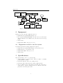
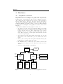
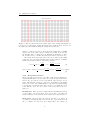
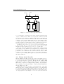
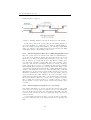
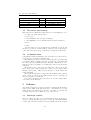
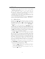
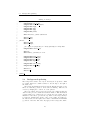
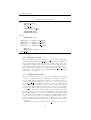
FPGA Shoot ’em up
Jonas Johannesson [email protected]
Philip Ljungkvist [email protected]
Syed Zaki Uddin [email protected]
Abstract
This report describes how to implement a side scrolling shot’em up
game on a Digilent Nexys 2 fpga board. The game is controlled by a
rotary encoder Pmod and is displayed on a VGA monitor.
The game consists of a Xilinx microblaze IP processor and a purpose
specific graphical accelerator. The graphical accelerator is responsible
for drawing all graphics to the monitor. All graphics are built from 16x16
pixel blocks. These blocks are stored in a RAM. The graphical accelerator
consists of two parts. One part is responsible of drawing backgrounds and
the other part is used to draw the foreground. The accelerator reads
information about where on the screen objects should be drawn from two
different RAMs. The part responsible of drawing the foreground uses a
row buffer.
When the graphical accelerator has finished drawing one full frame
it generates an interrupt to the CPU. The CPU then reads input from
the controller and calculates new positions for the objects on the screen.
The CPU is also responsible of detecting and handle collisions between
different objects on the screen. Collision detection is done using axis
aligned bounding boxes.
The game is output with a resolution of 320x240 pixels @ 60 Hz. The
maximum numbers of simultaneous objects on the screen is 256.
2
Contents
Contents
1 Introduction
1.1 Overall Design . . . . . . . . . . . . . . . . . . . . . . . . .
1.2 Changes from the project proposal . . . . . . . . . . . . . .
4
4
4
2 Equipment
2.1 Equipment needed to run the system . . . . . . . . . . . . .
5
5
3 Specifications
5
4 Hardware
4.1 Graphical accelerator . . . . . . . . . . . . . . . . . . . . .
4.1.1 Background renderer . . . . . . . . . . . . . . . . .
4.1.2 Foreground renderer . . . . . . . . . . . . . . . . .
4.2 Rotary wheel decoder . . . . . . . . . . . . . . . . . . . .
4.2.1 Interfacing Rotary Encoder to NEXYS 2 FPGA
board . . . . . . . . . . . . . . . . . . . . . . . . .
4.2.2 Interfacing Rotary Encoder to our design . . . . .
4.3 Processor and memory . . . . . . . . . . . . . . . . . . . .
4.4 Communication . . . . . . . . . . . . . . . . . . . . . . . .
.
.
.
.
6
6
7
8
9
.
.
.
.
10
10
11
11
5 Software
5.1 Interrupt routine . . .
5.2 Adding objects . . . .
5.3 Background updating
5.4 Moving objects . . . .
5.5 Collision detection . .
.
.
.
.
.
11
11
12
13
14
14
.
.
.
.
.
.
.
.
.
.
.
.
.
.
.
.
.
.
.
.
.
.
.
.
.
.
.
.
.
.
.
.
.
.
.
.
.
.
.
.
.
.
.
.
.
.
.
.
.
.
.
.
.
.
.
.
.
.
.
.
.
.
.
.
.
.
.
.
.
.
.
.
.
.
.
.
.
.
.
.
.
.
.
.
.
.
.
.
.
.
.
.
.
.
.
.
.
.
.
.
6 Conclusions and Discussions
15
6.1 Possible improvements . . . . . . . . . . . . . . . . . . . . . 15
7 Contributions
16
A User Manual
17
3
Introduction
1
Introduction
Side scrolling Shoot ’em up games is a popular genre of games. This
report describes a system that allows you to play such a game on a VGA
monitor with a Nexus2 Spartan3 development board. To control the game
the player uses a rotary wheel that doubles as a firing button.
The idea of the game is to let the player control a spacecraft while
computer controlled enemy spaceships tries to destroy the players spaceship. The players spacecraft is located in the left part of the screen. The
player can move the spacecraft up and down in the screen by rotating a
wheel. The player can also press this wheel to make the spaceship fire to
destroy the enemy spaceships. While doing this, enemy spaceships will
show up in the right part of the screen and fly towards the players spaceship. The enemy spaceships will also be able to fire, if they hit the players
spacecraft it will be destroy.
The system is built around a Xilinx microblaze soft CPU [5]. To reduce
the CPUs load and memory usage, a graphical accelerator was designed
and connected to the CPU.
There is allot of different approaches to how you draw the graphics
to the screen. The graphics used in this project is built around blocks of
16x16 pixels. The background and spaceships are built up by grouping
these blocks together in different ways. The CPU is responsible of were
these blocks are positioned on the screen and the graphics accelerator does
the actual drawing to the screen.
1.1
Overall Design
The system is built around a Xilinx microblaze processor [5]. Two peripheral units are connected to this via the PLB bus [2]. A rotary wheel
decoder and a graphical accelerator. Also a VGA controller is used that
generates the sync signals to the VGA monitor by using two internal
counters hcount and vcount. Since VGA standard is 640x480 pixels and
the resolution of the game is 320x240 pixels, the Hcount is set to count
to a value twice that of the standard. For a overview of the system see
figure(1).
The rotary wheel decoder translates the signal coming from the rotary
wheel encoder and indicates to the CPU if the wheel has been turned
clockwise or counter clockwise.
The graphical accelerator consists of two parts. One that draws the
background and one that draws the foreground i.e. the spaceships and
the bullets being fired. The part responsible for the foreground uses a line
buffer.
The system clock used for the whole system has a frequency of 50 MHz
1.2
Changes from the project proposal
To allow for larger software, the external memory on the development
board was used.
The size of the background was changed from 21x15 tiles to 32x15
tiles. This was done to allow the background to wrap around the edges of
the screen while scrolling.
An additional background layer was added to allow more advanced
graphics.
4
Equipment
External RAM
Row BRAM0
BRAM
Row BRAM1
Monitor
PLB
microblaze CPU
B
REG.
Graphics acc.
Palette
BRAM
VGA
controller
PLB
R
Bitmap
BRAM
Tile
BRAM
Object
BRAM
Figure 1: Block diagram of the hardware design
2
Equipment
In this project the following equipment was used:
• Digilent Nexys 2 Spartan3E 1200 kgates [1]
• PC computer running Xilinx EDK v.12.2 [4] connected to the Nesys2
with an USB-cable and a RS232 cable, the later is used for debug
prints
• VGA monitor
• Digilent PmodENC - Rotary encoder [3]
2.1
Equipment needed to run the system
To run the system the following equipment is required:
• Digilent Nexys 2 Spartan3E 1200 kgates development board
• Digilent Adept, to program the board
• Digilent PmodENC - Rotary encoder
• VGA monitor
3
Specifications
The system should be able to do the following:
• output graphics to a VGA monitor with a resolution of 320x240
pixels (640x480 @ 60Hz).
• update the players position by rotating a wheel.
• update the game with enemy spacecrafts at different times
• detect collisions between the players spaceship and enemy spacecrafts and fire. And in a similar way detect collisions between the
players fire and enemy spacecrafts.
5
Hardware
4
Hardware
4.1
Graphical accelerator
The graphical accelerator consists of two parts. One for drawing the
background and one for drawing the foreground. The output of these
blocks is sent to a block referred to as pixel selector If there is non zero
data coming from both block then the pixel selector sends the data from
the foreground renderer to the screen. If non zero data is being sent from
only one of the blocks, this blocks data is sent to the screen. It also uses
six different BRAMs. For details about the contents of the different RAMs
see figure(3). A block diagram of the graphical accelerator can be seen in
figure(2).
The different RAMs used in the graphics accelerator are:
• Tile RAM : stores the 16x16 pixel graphical building blocks. This
RAM is used both by the background renderer and the foreground
renderer, and is connected to these with separate ports to allow
simultaneous access. It consists of 16384 words of three bits per
word. This correspond to 64 16x16 pixels blocks. Each word holds
a colour for a specific pixel.
• Object RAM : stores the position, what 16x16 pixel block to use and
what palette to use for all movable objects. It consists of 256 27 bits
words.
• Tilemap: stores a map of the 16x16 pixel blocks that makes up the
background. It consists of 1024 9 bit words.
• Two BRAMs for the row buffer, they each consists of 320 words and
stores values for each pixel on a row. These are referred to as Row
RAMs.
• Palette: keeps the different colour palettes.
Monitor
Pallette
Scroll
value
Row buffer 0
Foreground
renderer
Background
renderer
Row buffer 1
Tile map
Tile RAM
Object RAM
Figure 2: overview of the hardware used in the graphical accelerator
6
4.1
Graphical accelerator
8
7
6
5
flip palette#
0
tile#
2
0
colour
26
18 17
x
9
8
3
y
tile#
12
10 9
colour
8
2
1
palette#
7
palette#
0
0
object#
Figure 3: Figures showing words in the different RAMs used in the graphical
accelerator. The first figure from the top shows a word in the tile map, the
second is a pixel in a tile, the third shows a word in the Object RAM and the
figure at the bottom shows a word in the Row RAM
All graphical elements on the screen is built from 16x16 pixels graphical building blocks (from now on referred to as tiles). These are stored
in a RAM memory. The content of this memory is hard coded and it
can’t bee changed, so it works as if it were a ROM. At each address in
this memory a numerical value is stored, representing a colour for every
individual pixel. To allow different colour schemes for the same tile, four
different palettes of colour are used. This means that if as an example
the number 3 is read from the tile memory, this number can represent
four different colours depending on which of the four palettes that’s being
addressed.
After completing each frame an interrupt signal is sent to an interrupt
controller. This is a signal for the CPU that the frame is completed and
a request for information about the next frame.
4.1.1
Background renderer
The visible area of the screen is 320x240 pixels. This equals to 20x15
16x16 pixel tiles. To allow easy scrolling of the game field the background
is actually a grid of 32x15 tiles. By changing a variable referred to as the
scroll-value between 0 and 511 the 20x15 tile visible area is moved over
the wider background. Since 512
= 32 is a power of two the visible area
16
will fold over the 32x15 grid so that when it moves over the rightmost
column it will show the beginning of the 32x15 image. See figure(4).
To give the illusion of depth in the image two different 32x15 grids
are used, which can be scrolled independently. One of the background
layers has priority over the other. By letting the lower priority grid scroll
slower than the other an illusion of different distance to the background
is created.
Information about which tile that should be positioned were in the
32x15 grids is read from the tile map, see equation(1). The data read also
contains information about which of the four palette to use and whether
or not it should be flipped 180 degrees horizontally. This data combined
with the values of the VGA-controllers hcount and vcount and the scrollvalue is used to address a specific pixel in the ram containing the tiles,
see equation (2). The value at that pixel is used together with the palette
7
4.1
Graphical accelerator
Figure 4: Here it’s showed how the visible part of the background (thick red
box) moves over the larger background from left to right and how it folds over
the right edge and starts showing the background at the left.
number to address a specific colour in the palette RAM. Since a 50MHz
system clock is used and a pixel is drawn every fourth clock cycle the
Hcount value has to be divided by four. Each line is drawn twice so when
the Vcount is used to calculate the addresses it must be divided by two.
The background renderer uses four clock cycles to draw one pixel. This
works since were only using 320x240 pixels resolution instead of 640x480
which is the default resolution of the VGA-controller.
tilemap addr = ⌊
V count
2
16
bitmap addr = tilemap data∗256+(
4.1.2
⌋ ∗ 32 +
Hcount
4
+ xscroll
16
(1)
V count
Hcount
%16)∗16+(
+xscroll)%16
2
4
(2)
Foreground renderer
The foreground renderer uses a row buffer. This works by having two
identical RAMs that are as wide as the screen (320 words) and two hardware blocks, one referred to as row reader and the other referred to as row
writer. The hardware blocks are connected to the RAM ports via multiplexers. For every row the RAM that the reader/writer is reading/writing
to is switched. So that when the writer works on one RAM the reader
works with the other. For an overview of the foreground renderer see
figure (5).
Row Reader The row reader reads from the Row RAM At the address
corresponding to the next position of the screen. The colour value and
palette address stored at each address is read and sent to the pixel selector.
Row writer The Row writer prepares the next line to be drawn. It
does this by iterating through every word in the object RAM. It reads
the y coordinates for each object and compare this to the current row
8
4.2
Rotary wheel decoder
Tile RAM
Object RAM
To palette
Writer
Reader
Row
Buffer0
Row
Buffer1
Figure 5: overview of the foreground renderer
i.e. Vcount. If the object isn’t present on the current row then the next
objects coordinates is read. If the object is present on this row the first
x-coordinate is read. The x-coordinate together with Vcount is used to
calculate an address to the Tile RAM. The valued stored in the Tile RAM
is written to the to the Row RAM at the address corresponding to the xcoordinate, also the number of the current object is stored at this address
as a label of what object this pixel belongs to. This step is repeated 15
times until all pixels of the object has been written to the RAM.
It takes 18 clock cycles to copy one row of an object from the tile ram
to the row buffer. Two cc to read the position of an object and decide if
and where in the row buffer to store it, 16 cc to copy the data.
The Row writer also implements a collision detector that currently
isn’t working correctly. This detector is implemented by reading from the
Row RAM before writing to it. If something is already written to this
position the owner of this data is stored and a collision is detected. Then
a collision is set in a register at the positions corresponding to the number
of the two objects colliding. This register is accessible for external devices
through the PLB bus.
4.2
Rotary wheel decoder
The PmodENC Rotary Encoder Module [3] has a rotary shaft encoder to
provide Rotate-Left (or) Rotate-Right function along with a push button
to provide button-pressed operation. This module also includes SWT
sliding switch to either on/off the module. There are 6 pins included in
this module, one pin serve for Supply Voltage (VDD) , one pin assigns to
Ground (GND) , and four pins assigns to outputs (A,B,BTN,SWT) from
the Pmod Encoder module
Initially the rotary encoder will be at stationary state. But, when
shaft is rotated, Two outputs (A and B) provides the encoded information
for rotary shaft operation, which tells us weather rotary shaft have been
rotated left or Right. Depending upon the direction of the shaft rotated,
one output (either A or B) changes one before the other as shown in the
9
4.2
Rotary wheel decoder
timing diagram see figure(6)
Figure 6: Timing diagram of A and B output for rotation right
Rotate-Left operation also produces almost same timing diagram except output B will drop to 0 first before the output A. Output SWT produces the output logic high when SWT is open, otherwise output SWT
will be low. Whenever the push button is pressed it will drive the BTN
output high otherwise output BTN is pulled down.
4.2.1
Interfacing Rotary Encoder to NEXYS 2 FPGA board
The basic operation needed to interface Pmod Encoder with FPGA is to
decode the given outputs (A and B) and extract its direction and event
information. Looking to the timing diagram in figure (6), it can be seen
that, if output A goes high while B is low the shaft is rotating clockwise, whereas if output B goes high while A is low it is rotating counter
clock-wise. The direction and Event extraction is carried out using a
rotary contact filter, in order to avoid glitches produced from mechanical
shaft. This filtering is performed by detecting only the first change on the
output and ignoring all subsequent activities on that signal until a change
on the second output has been detected. Later this value will be registered
using flip-flop to provide clean a1 and a2 signals. Output a1 provides the
information regarding the event triggered on direction change, whereas
a2 provides the direction value. Whenever an event is encountered on a1
signal, then depending upon the value on a2 at that instance extracts the
direction information. Whenever event is detected on signal a1 and the
value of signal a2 is 0, then it is said to be rotating clock-wise operation,
whereas if value on a2 is 1 when event is 1, then it is Rotating counter
clock-wise.
4.2.2
Interfacing Rotary Encoder to our design
Our design requirement is to provide only direction value at the output
from rotary encoder along with a reset signal to the decoder. Initially the
direction output is at stationary state. But whenever the shaft rotary has
been moved, the output to the direction output value changes as described
in the given table.
A reset signal is used in the design to reset the module to stationary
state after reading the value of the output direction after completing each
frame.
10
4.3
Processor and memory
Event(a1) and direction(a2)
00
01
10
11
4.3
Value
00
00
01
10
function
Stationary
Stationary
Clock-wise rotation
Counter clock-wise rotation
Processor and memory
This system uses a Xilinx Microblaze CPU. It’s a 32-bit RISC-processor.
A compiled program is divided into:
• .text (code)
• .data (initialized static and global variables)
• .bss (uninitialized or zero initialized static and global variables)
• heap
• stack
.text and .data is stored in 32kB dual port BRAM. .bss, heap and
stack are stored in an external 16Mbyte 16bit wide ram on the nexys-2
board. The CPU uses a 1kbyte cache when accessing the external ram.
4.4
Communication
Communication with external unit is done by letting some of the memories
and registers be accessible via the PLB bus.
The Graphical accelerator generates an interrupt after every frame has
been drawn. This is a signal to the CPU to update the scroll values and
the data in the Object RAM and in the Tile map. This should be done
while the monitor is in blank to avoid flickering on the screen when data
is changed.
The Palette is also connected to the PLB bus to allow some special
effects in the game, such as letting the colours of objects change while
using the same palette. This is used in the game to make stars in the
background flash.
The register that holds the collisions from the malfunctioning collision
detector is also accessible via the PLB bus. Since its a 256 bit register it
takes 8 clockcykles to read from it.
To read the output from the rotary wheel decoder the output-register
is accessible via the PLB bus.
5
Software
All software is written in C. It is responsible for updating the information
in the Object RAM, in the Tile map and to check if there’s been any
change in the control wheels state. It is also responsible of detecting and
resolving collisions between different objects on the screen.
5.1
Interrupt routine
After every frame the CPU receives an interrupt from the graphical accelerator. When interrupted the CPU executes the interrupt handling
routine. The CPU then updates the Object RAM and the tile map in
11
5.2
Adding objects
the graphics accelerator. This data is the positions of all the graphical
components for the next frame.
Then the register in the rotary wheel decoder is read. The register can
have three different values, clockwise or counter clockwise or stationary.
The register also contains the state of the firing button. If any changes is
recorded the state of the player is updated accordingly.
When all memories has been updated and all registers has been read
the interrupt routine sets a flag, used to indicate that the the state of the
game for the next frame is to be updated.
To keep track of time in the game a global variable global frame counter
is used to count how many frames that passed since the game started. This
is updated in the interrupt routine after every frame.
5.2
Adding objects
By using the global frame counter variable it’s possible to keep track of
when an object should be added to the game. All events are stored in an
array with elements of the type event t sorted by the time stamps of each
event with the earliest event at position 0. When global frame counter
is equal to the time stamp of an event a call is made to the function
create enemy.
To describe an objects characteristics a struct enemy t is used. It
stores information such as how the object should move. How many tiles
it should consist of (1 to 4 different tiles). If it shoots and if so how often
it shoots and what kind of bullets. How big the hit box should be and
how many hits it can survive. The movement is controlled by a movement patterns array which is a two dimensional array of 64x2 elements,
every element holds the change in position for x and y for the next frame.
For a complete view of the structure see listing(1).
struct enemy list entry is a linked list that stores all objects currently
on the screen. Whenever a new object is added malloc() is called to
allocate new memory to the heap. It stores information such as what
hit box belongs to the object, what the current position on the screen is
and how many more hits the enemy can take. For a complete view of the
structure see listing (2). Every time the screen updates this list is iterated
and the state of each object is updated e.g. how many more hits it can
take, what the next position is according to its movement pattern, what
palette to use (this might change during the game to allow some special
effects such as displaying a flashing spaceship). If an object shouldn’t be
present on the screen anymore, the object is removed from this list and
free() is called.
struct event t keeps information about when an object should be created, where it should be positioned, what enemy t it should have and how
many objects of this kind that should be created.
To add a new object the following has to be done:
• Create an enemy t and assign to it: a movement pattern, the number
of tiles to use, firing frequency, hit box size and an id to help to
resolve collisions with this object.
• create an event t with the start position and start time for the object
an put it in the events array.
12
5.3
Background updating
Listing 1: enemy t
1
2
3
4
5
6
7
typedef struct{
unsigned
unsigned
unsigned
unsigned
unsigned
unsigned
long
char
char
char
char
char
num of objs;
movement pattern;
tile[4];
dx[3];
dy[3];
palette;
8
9
short xmin,xmax; //delete outside area
10
11
12
13
14
15
short
short
//hit box
short
short
hit minX;
hit minY;
hit width;
hit height;
16
17
18
//0 = player, 1= players shot, 2 = enemy spaceship, 3= enemy shots
unsigned short collision type;
19
20
21
short life;
short lifetime; //in frames, if −1 inf
22
23
24
25
26
unsigned
unsigned
unsigned
unsigned
short burts period;
short burts length;
short shot period;
char single shot;
27
28
29
unsigned char num of shots;
unsigned char shot type[2];
30
31
32
short shot x;
short shot y;
33
34
} enemy t;
5.3
Background updating
The background consists of two layers. Both layers are updated column
by column. Each new column is written to the tile map to the right of
the visible area.
The background furthest back shows stars in different sizes and colours.
These are randomly generated. Some stars are flashing. This effect is
created by changing the colour in one of the palettes.
The new column of the top layer is generated by a function that uses
data from the previous column and a random number. This information
combined with a set of rules is used to generate the new column. For an
illustration of the rules to generate the top outline of the background layer
see figure(7). Similar rules apply to the bottom outline. In addition to
the rules described in the figure, rules exists for maximum and minimum
y positions of the tiles. The rules only apply for the background outline.
13
5.4
Moving objects
Listing 2: enemy list entry
1
2
3
4
5
typedef struct{
struct list head list;
short x,y;
enemy t∗ e type;
unsigned long start frame;
6
unsigned char objs[4];
unsigned char palette;
7
8
9
10
11
//hit box
unsigned short boxId;
12
13
14
15
16
short
short
short
short
minX; // x+width/2 − hit width/2
minY; // y+height/2 − hit height/2
maxX; // x+width/2 + hit width/2
maxY; // y+height/2 + hit height/2
17
18
19
20
short life;
short lifetime; //in frames, if −1 inf
} enemy list entry;
5.4
Moving objects
Once every frame a call to the function move enemy is made. This function iterates through the enemy list entry list. For each element in the list
the movement pattern of each object is read and the position of the object
is updated accordingly. The movement pattern is stored in an array of
64x2 elements, where each elements keeps the change in x and y for one
frame. This array is addressed every frame with (global frame counter (start frame of the object)) modulo 64. This makes the movement cyclic
with a period of 64 frames.
5.5
Collision detection
To detect collisions between object, every object is assigned an axis aligned
bounding box. These boxes stores min/max x/y coordinates for the area
that can collide also known as a hit box. Every box also keeps an reference
to the enemy list entry that the box belongs to. All boxes are stored
in struct collision list which holds an array of all boxes. This array is
sorted by the min x coordinate of the box and a collision detection is
made between all adjacent boxes in this array. The sorting is done using
insertion sort. If any collisions are detected they are stored in an array.
To detect collisions the extreme values are compared with each other.
First the max x for box A is compared with min x for box B. If max x is
less then min x then the object can’t be colliding and 0 is returned. Then
the other max min coordinates is compared in a similar fashion (min x
box A ¿ max x box B, max y box A ¡ min y box B and min y box A ¿
max y box B) if any of these tests are true a collision can’t have occurred
and 0 is returned. If all tests are false then a collision has occurred and 1
is returned.
To handle the collisions a function handle collisions is used. It com-
14
Conclusions and Discussions
case 1
case 2
case 3
alt. 1
alt. 2
alt. 3
Figure 7: Here the rules for choosing tiles are demonstrated. In case 1 the
previous tile is a full box. The next tile can be any of the three alternatives. In
case 2 the previous tile is a slope downwards. The next tile can only be either
a full box or another one of the same kind. In this way sharp points in the
background are avoided. Similar rules apply for case 3.
pares the collision type for the two objects colliding. The collision type is
stored in the struct enemy t. By comparing the collision types its possible
to know what sort of objects are colliding and take actions thereafter. E.g.
if one object with a collision type that corresponds to a bullet from the
player collides with an object with a collision type of a enemy spacecraft,
damage should be inflicted to the enemy spacecraft.
6
Conclusions and Discussions
The system takes up 2754 slices on the FPGA (31% of the available slices).
25 out of 28 BRAM blocks. The synthesis report estimates a maximum
clock frequency of 161 MHz.
The software takes up 24854 bytes of instruction memory.
6.1
Possible improvements
By designing the background renderer differently, four layers of background could have been implemented in the same amount of clock cycles,
without adding more BRAMs. This would be possible since the background renderer uses four clock cycles and only one of them is used for
address calculations. This makes it possible to pipeline this process.
The original plan was to create the background in advance and store
it using RLE (Run Length Encoding) compression, and to implement
software to decode the background. This was omitted because of time
limitations.
15
Contributions
The foreground renderer includes a collision detector that doesn’t work
to our satisfaction. If it is made properly the CPU workload would be
decreased allot. But it would also make the collision detection less configurable since no hit boxes with variable size could be used.
To sort the array of hit boxes insertion sort is used. By implementing
a faster sorting algorithm such as quicksort the execution time would
probably be reduced. Quicsort however is a recursive algorithm which
uses more memory.
To allow more variable game play, scrolling in the Y-axis could have
been implemented by extending the tilemaps and the background renderer. This would of course increase the memory usage, especially if four
background layers were implemented.
All enemies uses the same graphics. The game would look better if
different graphics were used. Especially for the final boss.
The movement of enemies are very repetitive. By letting every enemy t have a list of different movement patterns instead of just one. More
complex movement would be possible.
7
Contributions
The members of the group contributed with different parts of the system.
• Philip Ljungkvist
The basic idea behind the graphical accelerator. The graphics of
the game such as the spaceships. The idea of having a movement
pattern assigned to every enemy.
• Jonas Johannesson
The idea of having all properties of an enemy stored in the struct
enemy t. Wrote this report.
• Syed Zaki Uddin
Made the Interface and decoder to the rotary encoder. Wrote the
part about the rotary decoder in this report.
The design and implementation of most of the hardware and software
was made by Philip Ljungkvist and Jonas Johannesson working together.
References
[1] Nexys 2 http://digilentinc.com/Products/Detail.cfm?NavPath=
2,400,789&Prod=NEXYS2.
[2] Plb
http://www.xilinx.com/support/documentation/ip_
documentation/plb_v34.pdf.
[3] Pmodenc
http://digilentinc.com/Data/Products/PMOD-ENC/
PmodENC_rm_RevA.pdf.
[4] Xilinx
edk
http://www.xilinx.com/products/design-tools/
ise-design-suite/embedded-edition.htm.
[5] Xilinx Inc. http://www.xilinx.com/tools/microblaze.htm, 2011.
16
User Manual
A
User Manual
To use the system, the Nexys 2 board needs to be connected to a computer
through a USB-cable. The Pmod encoder needs to be connected to the
top row of Pmod connector JA. A VGA-monitor needs to be connected to
the VGA-port. Download the file shmup/shmup/top download.bit using
Digilent Adept.
To control the spaceship turn the rotary shaft clockwise or counter
clockwise. To fire press the rotary shaft. The player has 5 lives to complete
the game. If the player runs out of life press fire after a couple of seconds
and the game will restart.
17