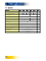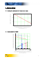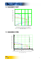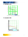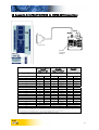
1
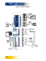
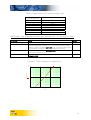
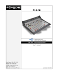
AX-V MAIN USER MANUAL Release 5.2 Date: Feb. 25 2002 Supported models: AX-V 06094 AX-V 10144 AX-V 10284 AX-V 23404 AX-V 25554 Phase Motion Control s.r.l. Via Adamoli, 461 16141 Genova – Italy Tel. +39 (010) 835161 Fax +39 (010) 8355355 e-mail: [email protected] General connection diagram 1 2 3 4 5 6 7 8 9 10 11 12 13 14 15 16 Analog Input 2 + Analog Input 2 Analog Output 2 Analog Output 3 Ground Digital Input 4 Digital Input 5 Digital Input 6 Digital Input 7 Digital Output 4 Digital Output 5 Digital Output 6 Digital Output 7 Encoder Simulator Ch. A Encoder Simulator Ch. B Encoder Simulator Index 1 2 3 4 5 6 7 8 9 10 11 12 13 14 15 16 17 18 19 20 Analog Input 0 + Analog Input 0 Analog Input 1 + Analog Input 1 Analog Output 0 Analog Output 1 Ground Digital Input 0 Digital Input 1 Digital Input 2 Digital Input 3 Digital Output 0 Digital Output 1 Digital Output 2 Digital Output 3 Rele' Common Rele' Open Rele' Closed +24 V Input 0 V Input -2- Index of Contents 1 Quick Overview................................................................................................ 4 2 What is a motion control platform?.................................................................. 4 3 To get started .................................................................................................. 6 4 Hardware Description....................................................................................... 9 5 Emergency and power fail condition handling .................................................. 12 5.1 General.......................................................................................................... 12 5.2 Emergency stop with inertial loads; safety brakes ........................................... 12 5.3 Power fail with high energy load .................................................................... 13 5.4 Thermal protection delay................................................................................ 13 6 Technical Specifications.................................................................................... 14 6.1 Electrical specifications ................................................................................... 14 6.2 Physical Data.................................................................................................. 15 7 Electrical Ratings .............................................................................................. 16 7.1 Derating of output current with temperature increase .................................... 16 7.2 Area Operativa AX-V 06094........................................................................... 16 7.3 Area Operativa AX-V 10144........................................................................... 17 7.4 Area Operativa AX-V 10284........................................................................... 17 7.5 Area Operativa AX-V 23404........................................................................... 18 7.6 Area Operativa AX-V 25554........................................................................... 18 8 Electrical Connections ...................................................................................... 19 9 Mechanical Installation..................................................................................... 28 10 AX-V Fault codes .......................................................................................... 28 11 System Parameters ........................................................................................ 31 11.1 Current loop .................................................................................................. 31 11.2 Braking resistor .............................................................................................. 31 11.3 Encoder counters ........................................................................................... 32 11.4 Intradrive ....................................................................................................... 34 11.5 Analogue outputs .......................................................................................... 34 11.6 Serial link RS485 ............................................................................................ 34 11.7 Motor thermal protection............................................................................... 34 11.8 Position/Speed Loop....................................................................................... 35 11.9 Expansion board ............................................................................................ 35 11.10 Emergency braking ..................................................................................... 35 12 CE conformity of AXV platforms, Ultract, Minact, Wave motors..................... 36 12.1 Wiring recommendations and CE-typical system for conformity to EMCD and LVD 36 12.2 EC Declaration of Conformity for the purposes of EMCD e LVD...................... 36 12.3 Introduction: EC directives.............................................................................. 36 12.4 LVD Directive ................................................................................................. 36 12.5 Product safety................................................................................................ 37 12.6 Application as directed – Scope of application ................................................ 37 -3- 12.7 Installation ..................................................................................................... 37 12.8 EC Declaration of Conformity......................................................................... 37 12.9 The EMCD Directive (89/336EWG) ................................................................. 38 12.10 Installation as specified................................................................................ 38 12.11 EC Declaration of conformity ...................................................................... 39 13 1 Appendix A: ULTRACT MOTORS to DRIVE AXV Connections ....................... 40 Quick Overview The AXV programmable motion control platform is characterised by an innovative power control hardware which is fully personalised by software and configured via a PC link. For hardware installation information, read on in this hardware manual. For information on the PC resident control and configuration tool AXV Cockpit, refer to the AXV Cockpit Manual. For information on specific functions of all applications refer to HTML help pages in configuration tool AXV Cockpit. For information on programming refer to the software manual “Programming AXV” in the CD bundled with the platform. 2 What is a motion control platform? AX-V is the first realisation of a novel concept in motion control technology. AX-V is a configurable motion control platform, based on a very fast DSP dedicated to real time servo control application (VECON) integrated into a versatile and innovative power control hardware. The result is a fully configurable IGBT drive, particularly suited for high bandwidth brushless PM motor servo control, which can be configured, just by loading an application from a software library, as a digital drive, an intelligent axis controller, an electric gear, an electronic cam or, more generally, a fast motion control PLC or GPLC. The AXV drive is fully controlled by software; no hardware adjustments are needed or possible. The control software, which personalises the unit, as well as all the application and tuning parameters, are stored in the unit non volatile memory and are accessed and edited by linking the drive with a PC. Such a start-up connection is usually performed via 1 the RS 485 serial port . The set of application data and tuning parameters, which are application specific, is the application database. To create, inspect, edit and copy this database, the AXV Cockpit configuration tool is supplied along with the platform. This tool is installed in the PC, which is used to perform the installation of the AX-V drive. AXV Cockpit works as the control centre of the drive during installation; it accesses all drive functions and parameters, identifies the unit and its operational life, and allows copying to and from 1 The AX-V platform is equipped with a multi drop, industry standard RS 485 serial link. If only a RS 232 connection is available, a RS 232 - RS 485 converter is necessary. -4- stored data and to duplicate installations. It also works as a powerful diagnostic tool by interfacing with the drive “flight recorder” function. Cockpit also implements application security by allowing a multilevel password access restriction. For more information about AXV Cockpit, refer to the AXV Cockpit Application Manual. Software enclosed in AXV platforms consists of Firmware and Application. Firmware manages operating system and basic resources of the platform: current loop, speed and position loop, protections and diagnostics. Parameters to configure these functions are detailed in chapter System parameters. Some firmware characteristics are: y Fully digital dual direct and quadrature current control loop, updated at 16 kHz, with 4 kHz control bandwidth; y Digital speed loop with true zero speed, PII2D controller2 with generalised feedforward, standard servo; y Interpolation of analogic encoder to increase resolution; y Autophasing routine for incremental encoders which can be activated from GPLC application; y Configurable encoder simulation output. Firmware is developed in Phase Motion Control and cannot be modified by the final user. Periodically new firmware releases are available at http//www.phase.it. New firmware is always compatible with older applications. Application contains the motion control program and logic management. To develope applications use the Global PLC, a programming environment which empowers the user with the ability to create his own automation project inside the drive. Within the limits of the available I/Os and of the program memory, all standard automation functions of the IEC 1131-3 PLC language are available, on top of the real time motion control ability of the AXV platforms, including the acquisition of two separate encoders. The PLC software runs three independent tasks, a fast one used for motion control purposes, which runs at 4 kHz, and two slow tasks, for all other uses, running at 125 Hz. The GPLC language is so powerful that very fast functions such as position control, electronic camshaft, trajectory control, electric gear, can be implemented together with dedicated sensor and I/O interface. This way, the AX-V, equipped with application specific, and private, software, can become the very control centre of an automation application. For detailed information on programming refer to “AXV Programming Manual” in the CD bundled with the platform. A set of basic Applications (with related GPLC source code) is provided with AXV platform. These applications can be loaded into the drive by means of AXV Cockpit (see manual). 2 PII2D controller: 4 compensation terms are available: proportional (speed), derivative (acceleration), integral (position) integral of position (with this term, zero steady state position error can be obtained). -5- In every platform at the end of factory tests, the standard application Speed-V is loaded (standard software): designed for classical applications, SpeedV turns the AXV in a versatile digital platform for brushless servo motors. Main features are: y Two different control mode: current or speed control; y Standard analogue interface +/- 10V differential or frequency input; y Internal ramp generator; y Capability to maintain in memory 8 different complete sets of tasks, with possibility to switch from one to another, on the fly, by digital inputs; y Electrical gear capability. For detailed information on SpeedV functions and I/O refer to related HTML pages available by opening the SpeedV3_4eng.par file with AXV Cockpit. 3 To get started The AX-V platform is a fully digital, fully configurable drive. To interface with the drive and to input the application parameters for the first time, a link with a PC is necessary. After programming, the drive can be either controlled via the terminals, the serial line, or a field bus option. For the drive initialisation, a PC running Win 9x, Me, 2000 or Window NT 4.0 or higher is required with a RS 485 serial line and at least 15 Mbytes free disk space is required. If no RS 485 serial line is available on the selected PC, a RS232-485 interface converter is required. Supplied components: y y y y AX-V hardware platform Pre-loaded VPLC firmware (all drives are supplied, unless otherwise specified, with the SPEED-V application set for Ultract II and SINCOS encoder) Application Parameter table (a default parameter set as stated above is supplied with the original control firmware and can be modified as necessary and saved) AXV Cockpit configuration tool CD containing: y Hardware manual (the present one) y AXV Cockpit configuration program manual; y AXV Programming manual; y AXV Cockpit software to program, interface, install and monitor the application in the AXV; y GPLC software to develop dedicated applications y copy of latest release of firmware; y directory BONUS with samples of GPLC programming; y Mechanical drawings of ULTRACT II motors, AXV drive in DXF format and DWF format; y Utilities to view and print manuals and drawings Necessary components for first initialization: -6- y y y y y y y AXV and selected motor. 198-465 Vac three phase power supply (not necessary for programming and uploading but necessary for testing the drive). 24-30 Vdc, > 0.6 A control power supply, unregulated (up to 1 Vpk-pk ripple) PC running Windows 9x, ME, 2000 or NT 4.0 or higher is required with a RS 485 serial line. If no RS 485 serial line is available on the selected PC, a RS232-485 interface converter is required (available on demand). The browser Internet Explorer 4.0 or higher must be installed (available on CD). 15Mbyte free space on hard disk. Software installation: y y y y y y Insert the supplied CD-Rom into the PC drive. If autorun is enabled the main application starts automatically; else, open page index.htm in root directory of CD with any browser internet (e.g. Internet Explorer). It is possible also run the file setup.exe in the folder d:\setup\axvsetup\disk1. Install AXV Cockpit in the PC After the end of setup restart the PC; To complete installation is needed run the file Run Me First in the menù Start>Programs->AXV Cockpit (to do only one time after installation). Minimum wiring requirements: For PC connection only: y Connect 24 V supply between +24 V and 0 V on C1 interface y Connect RS 485 line to PC y In this state, the drive can be queried and programmed. No high voltage power is necessary. Power wiring: y y y Wire motor phases to A, B and C terminals of power connector, respecting scheme enclosed with the motor. For this wiring is needed a shielded cable with a section appropriate for the nominal current of the motor. The shield must be connected to ground both on motor side and on AXV panel. In case of doubt, it is possible to check the phase sequence (and the encoder phasing) by means of Test Routine application. Wire external power supply to R, S and T terminals of power connector. NOTE: AXV drives are designed to work only with three phase supply at any voltage up to 460V (+10%). WARNING: A braking resistor is needed for proper use of AXV. To use internal one, connect an insulated jumper with section appropriate to the drive current between power terminals BR+ and DC+. To use an external braking resistor with higher rated power connect it to DC+ and BR- terminals (without the jumper between BR+ and DC+). Resistance values for external braking resistor must comply with the following table: -7- Model AX-V 06094 AX-V 10144 AX-V 10284 AX-V 25554 Min 60 Ω 38 Ω 20 Ω 10 Ω Max 80 Ω 50 Ω 25 Ω 13 Ω If an external resistor is used, two system parameters must be configured: SYS_R_BRAKE (R value in ohm) and SYS_PBRAKE_MAX (nominal power in watt). Firmware uses these values to activate thermal protection of braking resistor. Additional details in System Parameters paragraph. -8- 4 Hardware Description The drive platform is characterized by : Power stage: y y y y y y y Innovative Ac-Ac converter without DC bus electrolytic capacitor, which provides instant availability at power-on and correct input current waveform, in line with the future IEC 555 norm; Auto tuning of current limit vs. supply voltage and ambient temperature; single drive for 198-465 Vac supply; 16 kHz carrier power IGBT stage, 16 kHz ripple frequency, built-in full power, limited duty cycle brake resistor; full power braking chopper; Forced ventilation controlled by the drive temperature (the fan is turned on only above 70 oC) to limit dust accumulation; the drive temperature is monitored and available for programmable cycle self-limiting; Full power stage intrinsic protection (overtemperature, short circuit to ground and between motor wires) with fault condition non volatile storage. Control and power stages have separate and independent power supplies for emergency shutdown and debugging Real time temperature observer for each power chip, with adaptive current limit. High speed sensor interface two independent inputs, configurable: a (main) 4 channel analogue/digital encoder input (200 kHz BW) which can be programmed to receive the following signals: 1. SINCOS 5 channel encoder (2 absolute analogue tracks, 2 incremental analogue tracks, index) (default encoder). 2. Digital 6 track encoder (3 Hall commutation + 2 incremental + index) 3. Analogue 6 track encoder (3 Hall commutation + 2 analogue incremental + index) 4. Incremental digital encoder without commutation tracks (requires autophasing) 5. Analogue SINCOS 2 tracks encoder or Resolver1 6. Hall sensors 7. Incremental 2 track analogue encoder 8. SINCOS 5 track encoder with digital incremental track A secondary encoder I/O (500 kHz) which can be programmed as follows: 2 Digital 6 track encoder (3 Hall commutation + 2 incremental + index) 4 Incremental digital encoder without commutation tracks (requires autophasing) 6 Hall sensors 1 Resolver output signals must be connected to sine and cocine inputs of terminal S2 -9- REMARK: to provide for long supply cables, the encoder power supply can be programmed in the 5-15 Vdc range. Two high speed outputs: y Encoder emulation, any ratio with the main encoder, including index, on the S1 connector (alternative to secondary encoder input), line driver 5V differential; y Secondary encoder replica, 24 V single ended open collector, hard wire connection with the S1 encoder input (it is a replica of encoder emulation or of the secondary encoder, depending on option chosen) General purpose interface: 3 programmable differential analogue inputs 4 programmable analogue outputs 8+8 programmable digital I/Os Programmable mechanical relay contacts 1A, 250V. Communication: Opto isolated, multi-drop RS 485 asynchronous serial interface; Field bus option; 1 synchronous high speed serial line INTRADRIVE ultra high speed (1 Mbaud) serial loop interface to link up to 4 AX-V drives into a multi axis, multi I/O coordinated environment Hardware: IP 20 insulated enclosure with internal RFI shielding, book type Power and control interfaces with removable terminal/connector Encoder and serial interfaces via standard D connectors Built in ground bar (4 x M4) for cable shield termination Architecture: Nonvolatile program memory area: 256 kByte Processors: 40 MIPs Task timing: Current and drive monitor loops: 16 kHz Servo and position loop calculations: 8 kHz Fast task (user programmable): 4 kHz Slow task: (user programmable): 125 Hz Position and position targets registers: 64 bit words (232 turns with 1/232 resolution per turn) - 10 - Opzioni1 Digital I/O expansion board (12 inpit + 4 output) CanOpen expansion board Profibus expansion board 1 Only one option board can be installed on each drive - 11 - 5 Emergency and power fail condition handling 5.1 General The AX-V platform has been purpose designed with two completely separate power supplies. The power circuit is fed from the mains voltage, without preload timing; while the control part needs to be fed from a separate unregulated 24 V supply, which is converted by the internal switching regulator for all internal services and for the supply of motor encoders at the appropriate voltages. This design solution overcomes all uncertainties of timing and synchronisation between drive and control cabinet, by unifying the same power supply for all services, such as sensors, PLCs, switches and latches. In this way, all data are memorised and reset at the same time, and a simple back-up is possible for all machine information without backing up the main power too. The power stage without preload (and without storage capacitors) ensures that the main power is available to the drive without delay whenever the mains power switch is operated. 5.2 Emergency stop with inertial loads; safety brakes Many applications involving brushless servo drives move high inertia loads in short, fast cycles (typical example are Cartesian robots or pick and place machines). When the load is moving at top speed, a significant amount of energy is stored in the load, so that a sudden deenergization of the brake could be dangerous. It is therefore essential that, in the event of an emergency, the load is braked as quickly as possible. To resolve this problem, the use of a servo motor with a safety brake is sometimes considered. The simple use of a safety brake, however, is wrong and dangerous for the following reasons: y y Safety brakes designed for servo motors are stationary brakes. They are designed exclusively to hold a motor still when deenergized, typically for vertical translations. They are not designed to absorb any significant energy, also because their torque to size ratio is extreme. If used to stop a motor, instead of keeping it at standstill, they would wear quickly and eventually seize. The braking torque of an electrically driven brushless motor is always higher than that of the brake and the corresponding braking time is shorter. Consequently, the function “emergency stop” must be realized as follows: the emergency condition, because of safety regulation, must turn off the mains power to the drive; however, the auxiliary 24 V must be mantained, so that the drive is alive and can brake; at the same time, the emergency condition must generate a 0 speed reference that brakes the motor at maximum torque, using the kinetic energy of the motor. The drives regenerates energy from the motor to the DC bus until the motor speed is so low that the motor back EMF is less than approximately 10 V. At this speed, the DC Bus voltage falls, the drives locks in undervoltage and the motor is abandoned. - 12 - If the translation is vertical, and the motor is equipped with safety brake, only in this moment, the safety brake can be released. To time the release, the relay contacts in the drive can be used. The relay is switched by the DC Bus undervoltage, that corresponds to motor almost at standstill. When the emergency stop logic is realised as described, the machine encoders are kept alive and no index search or initialisation is required when normal operation is resumed. 5.3 Power fail with high energy load Mains power failure with a high kinetic energy load requires special control provisions. In this case, the auxiliary 24 V supply may not be available for a time long enough to stop the load. Two solutions are possible: To back up the 24 V supply with a small battery system. This is the highest quality solution; all encoders and sensors ride through the power failure and no reinitialization is required when the power supply is again available. When the back-up solution is not possible, the auxiliary 24 V should be generated with a switching power supply fed from the drive DC Bus. The drive is equipped with a special power fail routine that, irrespective of reference, when the DC bus falls, regenerates energy from the motor to keep the DC bus at just above the undervoltage level. In this way, the auxiliary power is made available to the system as long as there is kinetic energy in the load. A 0 speed reference or a braking ramp can be programmed as needed. Once more, a safety brake can be safely released only at the end of the braking cycle. The 24 V supply of the brake should be thus derived from the same switching power supply feeding the drive. The drive relay can be used to release the brake once all the kinetic energy has been dissipated. 5.4 Thermal protection delay When a load carries a high kinetic energy, an untimely deenergization due to a protection tripping can be dangerous. For this reason, the thermal protection of drive and motor is delayed (approx. 2 s) from the onset and the setting of the appropriate terminal signal, so that the load can be braked safely before the drive trips. - 13 - 6 Technical Specifications 6.1 Electrical specifications Electrical Specifications AX-V 06094 Supply voltage 0-506 Supply current 1) 9 Supply Frequency 0-400 Nominal power 2) 2.8 5 5 11 11.5 KW 6 (9*) 10 (14*) 10 (14*) 23 (36*) 25(32*) Arms 5 (6.5*) 8 (10*) 8 (10*) 18 (23*) 18.4(22*) Arms Peak current 9 14 28 40 55 Arms Output voltage Vin × 0.95 Vac PWM Frequency 16 KHz Efficiency at nominal power 4) 96.5 Form factor .9 Maximum braking current 100 Output current, < 100 rpm speed, S1 3) Output current, max speed 3) AX-V 10144 AX-V 10284 AX-V 23404 AX-V 25554 Units Vac 3 phase 14 28 40 55 Arms Hz 96.5 96.5 Aux. Supply Voltage 20-30 5) * For 230 Vac input supply 1) Peak Value 2) Input bridge losses included 3) Vin =380Vac, Tamb=40C, Freq. Comm. 16 kHz, Vout=Vin*.95 4) Excluded auxiliary supply losses 5) Not stabilized (max. ripple 1 Vpk-pk), > 0.6 A nom. 95 95 % of peak current Vdc - 14 - 6.2 Physical Data Physical Data AX-V 06094 AX-V 10144 Average brake power with internal resistor Power loss at nominal current Thermal capacity Mass Protection level Permissible vibrations AX-V 23404 AX-V 25554 100 120 200 160 180 300 1400 Cooling Size (WxDxH) AX-V 10284 Unità W 300 2800 W J/C Forced cooling 85x225x341 182x225x341 Mm 2.4 5.3 Kg IP20 0.5 g in every direction, 0-10 Hz Shocks 0.5 g Operating ambient temperature 0-50 o C -20-70 o C Storage temperature range Relative humidity Altitude 0-95%, non condensing 0-1000 mt; derate current by 3% each 100 m above 1000 m - 15 - 7 Electrical Ratings 7.1 Derating of output current with temperature increase Output current, % of nominal 120 100 80 60 0 10 20 30 40 50 Percentage variation of output current vs. o room temperature ( C) 7.2 Area Operativa AX-V 06094 Corrente dell’azionamento [Arms] e potenza resa [kW] 10 8 6 4 2 0 1 100 200 300 Vo Volt 400 500 497 Area operativa azionamento AX-V 06094 in funzione della tensione di uscita per alimentazioni 230, 380 e 460 Vac - 16 - 7.3 Area Operativa AX-V 10144 Corrente dell’azionamento, Arms, kW 20 15 10 5 0 100 200 300 400 500 Area operativa azionamento AX-V 10444 in funzione della tensione di uscita per alimentazioni 230, 380 e 460 Vac 7.4 Area Operativa AX-V 10284 Corrente di uscita [Arms] e potenza resa [kW] 30 25 20 5 0 5 0 1 100 200 300 Vo Volt 400 500 497 Area operativa azionamento AX-V 10284 in funzione della tensione di uscita per alimentazioni 230, 380,460 Vac - 17 - 7.5 Area Operativa AX-V 23404 Corrente dell’azionamento, 0 50 40 30 20 10 0 0 100 200 300 400 500 Area operativa azionamento AX-V 23404 in funzione della tensione di uscita per alimentazioni 230, 380 e 460 Vac 7.6 Area Operativa AX-V 25554 60 Corrente dell’azionamento 50 40 30 20 10 0 100 200 300 400 500 Area operativa azionamento AX-V 23404 in funzione della tensione di uscita per alimentazioni 230, 380 e 460 Vac - 18 - 8 Electrical Connections COMMAND TERMINAL C1 – FUNCTION AND SIGNAL DESCRIPTION Connector Terminal Phoenix 20 pin cod. 1847301 Pin N. Name Type Function Signal Description Positive signal of differential input Negative signal of differential input Positive signal of differential input Negative signal of differential input +/-10V, Zin = 10Kohm; if not used connect to GND +/-10V, Zin = 10Kohm; if not used connect to GND +/-10V, Zin = 10Kohm; if not used connect to GND +/-10V, Zin = 10Kohm; if not used connect to GND 1 R0P Analog Input 2 R0N Analog Input 3 R1P Analog Input 4 R1N Analog Input 5 AO0 Analog Output Programmable Output +/-10V f.s., 5 mA 6 AO1 Analog Output Programmable Output +/-10V f.s., 5 mA 7 GND Analog Ground 8 DI0 Digital Input Programmable Input 6.6 kOhm rel. to ground, 20-30 V 9 DI1 Digital Input Programmable Input 6.6 kOhm rel. to ground, 20-30 V 10 DI2 Digital Input Programmable Input 6.6 kOhm rel. to ground, 20-30 V 11 DI3 Digital Input Programmable Input 6.6 kOhm rel. to ground, 20-30 V 12 DO0 Digital Output Programmable Output PNP open collector, 24 V, 100mA max 13 DO1 Digital Output Programmable Output PNP open collector, 24 V, 100mA max 14 DO2 Digital Output Programmable Output PNP open collector, 24 V, 100mA max 15 DO3 Digital Output Programmable Output PNP open collector, 24 V, 100mA max 16 RLM Relay Contact Common relay ouput 1A, 250 Vac resistive 17 RLO Relay Contact N.A. relay contact 1A, 250 Vac resistive 18 RLC Relay Contact N.C. relay contact 1A, 250 Vac resistive 19 24V Aux Supply Regulation circuit Aux Alim. Voltage: 20-30 V referred to Pin 20 Absorbed current: 600mA. 20 0V Aux. Supply Neg Aux Alim. - 19 - COMMAND TERMINAL C2 – FUNCTION AND SIGNAL DESCRIPTION Connector Terminal Phoenix 16 pin cod. 1847262 Pin N. Name Type 1 R2P Analog Input 2 R2N Analog Input 3 AO2 Analog Output Programmable Output +/-10V f.s., 5 mA 4 AO3 Analog Output Programmable Output +/-10V f.s., 5 mA 5 GND Analog Ground 6 DI4 Digital Input Programmable Input 6.6 kOhm rel. to ground, 20-30 V 7 DI5 Digital Input Programmable Input 6.6 kOhm rel. to ground, 20-30 V 8 DI6 Digital Input Programmable Input 6.6 kOhm rel. to ground, 20-30 V 9 DI7 Digital Input Programmable Input 6.6 kOhm rel. to ground, 20-30 V 10 DO4 Digital Output Programmable Output PNP open collector, 24 V, 100mA max 11 DO5 Digital Output Programmable Output PNP open collector, 24 V, 100mA max 12 DO6 Digital Output Programmable Output PNP open collector, 24 V, 100mA max 13 DO7 Digital Output Programmable Output PNP open collector, 24 V, 100mA max 14 REA Digital Output 15 REB Digital Output 16 REC Digital Output Function Positive signal differential input Negative signal differential input Digital encoder repetition: Ch. A Digital encoder repetition: Ch. B Digital encoder repetition: Ch. C Signal Description of of +/-10V, Zin = 10Kohm; if not used connect to GND +/-10V, Zin = 10Kohm; if not used connect to GND NPN open collector 30 V, 100 mA NPN open collector 30 V, 100 mA NPN open collector 30 V, 100 mA - 20 - I/O EXPANSION BOARD (Option) Name Connector Terminal Phoenix 20 pin cod. 1847301 Type Function Description 1 +V_DO Supply Voltage Insulated reference for Digital Outputs Supply Voltage: 10-30 V to Pin 15 ( 0V ) 2 DO8 Digital Output Programmable output PNP open collector 100mA max 3 DO9 Digital Output Programmable output PNP open collector 100mA max 4 DO10 Digital Output Programmable output PNP open collector 100mA max 5 DO11 Digital Output Programmable output PNP open collector 100mA max 6 GND_DO Digital outputs Insulated gnd 7 DI8 Digital Input Programmable input 6.6 kOhm to gnd (Pin 1), 20-30 V 8 DI9 Digital Input Programmable input 6.6 kOhm to gnd (Pin 1), 20-30 V 9 DI10 Digital Input Programmable input 6.6 kOhm to gnd (Pin 1), 20-30 V 10 DI11 Digital Input Programmable input 6.6 kOhm to gnd (Pin 1), 20-30 V 11 DI12 Digital Input Programmable input 6.6 kOhm to gnd (Pin 1), 20-30 V 12 DI13 Digital Input Programmable input 6.6 kOhm to gnd (Pin 1), 20-30 V 13 DI14 Digital Input Programmable input 6.6 kOhm to gnd (Pin 1), 20-30 V 14 DI15 Digital Input Programmable input 6.6 kOhm to gnd (Pin 1), 20-30 V 15 DI16 Digital Input Programmable input 6.6 kOhm to gnd (Pin 1), 20-30 V 16 D17 Digital Input Programmable input 6.6 kOhm to gnd (Pin 1), 20-30 V 17 DI18 Digital Input Programmable input 6.6 kOhm to gnd (Pin 1), 20-30 V 18 DI19 Digital Input Programmable input 6.6 kOhm to gnd (Pin 1), 20-30 V 19 GND_IN Insulated Gnd digital inputs 20 GND_IN Insulated Gnd digital inputs N. Pin - 21 - CAN-BUS CONNECTOR J1 (Option C) Board connector type Cannon Sub-D 9 pin, male plug Pin N. Name Type 1 n.c 2 CAN-L Digital 5V 3 SHIELD Ground 4 n.c 5 n.c. 6 GND Ground 7 CAN-H Digital 5V 8 n.c. 9 n.c. Signal Description Signal CAN LOW Signal CAN HIGH PROFIBUS CONNECTOR (Option P) Phoenix Terminal 9 pins Pin N. Name 1 Shield 2 n.c. 3 RX/TX – B 4 n.c. 5 Type Signal Description Ground Cable shield connection Digitale 5 V Positive Receive/transmit Channel 0V Ground Ground reference for data signals 6 +5V Alimentazione Supply voltage for terminating resistance 7 n.c. 8 RX/TX - A 9 n.c. Negative Receive/transmit Channel - 22 - ENDAT ENCODER CONNECTOR J2 (Option C) Board connector type Cannon Sub-D 15 pin, male plug Pin N. Name 1 0 V / PTC- 2 n.c. 3 Type Signal Description Ground Connect 0 V, PTC- and shield CLK+ Digital 5 V Positive Clock Signal 4 CLK- Digital 5 V Negative Clock Signal 5 n.c. 6 +Vcc Power supply Encoder Supply Voltage 7 n.c. 8 PTC+ Digital 5 V Motor PTC thermal sensor input 9 DATA - Digital 5 V Negative Data Signal 10 n.c. 11 n.c. 12 n.c. 13 n.c. 14 DATA+ Digital 5 V Positive Data Signal 15 n.c. - 23 - ASYNCHRONOUS SERIAL PORT X1 CARD CONNECTOR - CANNON – D 9 PIN, MALE PLUG RS 485 multidrop, half duplex, insulated 2500 Vdc, standard speed 18.2 kB, max. hardware 1 MB Terminate line with 120 Ohm by means of panel switch Pin Name Type Function 1 Reserved 2 Reserved 3 LINE A (RS485) I/O RS485 line Channel A 4 SHIELD 0V + 100 Ohm Cable Shield 5 GND Signal Gnd 6 + 5V OUT Output Voltage Supply voltage for RS485 - RS232 converter 7 LINE B (RS485) I/O RS485 line Channel B 8 GND Signal Gnd 9 ENABLE485 Digital input Enable RS485 Mode (Active High) * Description Max. 20 mA Input NPN 5 V * Jumper with pin 6 to connect to RS 485 Devices - 24 - SENSOR CONNECTOR S1: FUNCTIONS AND SIGNAL DESCRIPTION1 CARD CONNECTOR - CANNON – D 15 PIN, MALE 1 Card Pin Conn. Name Type 1 GND+PTC 0V 2 H1N 3 H1 4 HALL 2 5 HALL 3 6 AUX +5V 7 ENC A+ 8 PTC 9 ENC I- 10 H2N 11 H3N 12 ENC A- 13 ENC B- 14 ENC I 15 ENC B Digital input Digital Input Digital Input Digital Input Function Signal Description Negative Hall Sensor phase 1 Square wave 0-5V Hall Sensor phase 1 Square wave 0-5V Hall Sensor phase 2 Square wave 0-5V Hall Sensor phase 3 Square wave 0-5V Encoder Ch. A Square wave 0-5V Aux Alim. Digital Input Digital Input Digital Input Digital Input Digital Input Digital Input Digital Input Digital Input Digital Input Motor thermal protection Negative Encoder Index Negative Hall Sensor phase 1 Negative Hall Sensor phase 1 Square wave 0-5V Square wave 0-5V Square wave 0-5V Negative Encoder Ch. A Square wave 0-5V Negative Encoder Ch. B Square wave 0-5V Encoder Index Square wave 0-5V Encoder Ch. B Square wave 0-5V In case of connection to Ultract motors, for encoder codes refer to Appendix A in this manual - 25 - SENSOR CONNECTOR S2: FUNCTION AND SIGNAL DESCRIPTION 1 CARD CONNECTOR – CANNON – D 25 PIN, MALE 1 Card Pin Name Type Function Signal Description 1 AANA Ana/digi Direct Input ch A Sine 1V pk/pk / digital 2 BANA Ana/digi Direct Input ch B Sine 1V pk/pk / digital 3 IANA Ana/digi Direct Input Index Sine 1V pk/pk / digital 4 GND+PTC 0V 5 COSN Ana/digi Negative Cos Input (ch. D+) Sine 1v PK/PK absolute 6 SINN Ana/digi Negative Sin Input (ch. C-) Sine 1v PK/PK absolute 7 H1 Digital Input Hall Ch. 1 Square wave 0-5V 8 H2 Digital Input Hall Ch. 2 Square wave 0-5V 9 H3 Digital Input Hall Ch. 3 Square wave 0-5V 10 GND+PTC 0V 11 PTC+ 12 RESEXN Analog Output 13 GND+PTC 0V 14 ANNA 15 Motor sensor terminal Positive resolver excitation Sinusoidal, 2 V pk-pk, 8 kHz Ana/digi Negative Input ch A Sine 1V pk/pk / digital BNANA Ana/digi Negative Input ch B Sine 1V pk/pk / digital 16 INANA Ana/digi Negative Input Index Sine 1V pk/pk / digital 17 COS Ana/digi Direct Cos Input (ch. D-) Sine 1V pk/pk absolute 18 SIN Ana/digi Direct Sin Input (ch. C+) Sine 1V pk/pk absolute 19 GND+PTC 0V 20 H1N Digital Input Negative Hall Ch. 1 Square wave 0-5V 21 H2N Digital Input Negative Hall Ch. 2 Square wave 0-5V 22 H3N Digital Input Negative Hall Ch. 3 Square wave 0-5V 23 ABREN Digital Input Enable encoder simulation Converts encoder input S1 in encoder simulation output, low active 24 RESEXP Analog Output Negative resolver excitation Sinusoidal, 2 V pk-pk, 8 kHz 25 AUX + Analog Output Encoder Alim. Programmable 4.5-15V, 250 mA In case of connection to Ultract motors, for encoder codes refer to Appendix A in this manual - 26 - POWER CONNECTOR Terminal CARD TERMINAL - PHOENIX PC4/10-ST 7.62 10 WAYS - FEMALE ULTRACT Pin ULTRACT motor wire Description connector colour A Motor phase A A Blue B Motor phase B B Red C Motor phase C C Yellow R Mains Supply R --- --- S Mains Supply S --- --- T Mains Supply T --- --- BR- External braking resistance connection (connect this terminal to DC+) --- --- DC+ Positive DC bus --- --- DC- Negative DC bus --- --- BR+ Connect to DC+ to enable internal braking system --- --- - 27 - 9 Mechanical Installation AX-V Dimensions Cod. AX-V 06094 AX-V 10144 AX-V 10284 AX-V 25544 a 85 85 85 182 a1 50 50 50 100 φ= 5 mm y y y y Install inside control cabinet; do not obstruct air flow (from low side to upper side) Avoid proximity (<40 mm) of walls and other devices on upper and lower side Check distance between drive and motor; if wiring exceeds 15m, insert appropriate snubber inductors Check cabinet inside temperature and cooling conditions 10 AX-V Fault codes Remark: fault conditions are identified either with the Flight Recorder function in AX-V Cockpit, or, when the PC is not connected, by a digital code on the signal LED. The code meaning is as follows: y Continuous green: normal operation y Continuous yellow: data transfer y flashing: fault: green=0, red=1 Example: green, green, red, red, red: 00111, motor Overtemperature All fault conditions are latched and are reset either by Control Panel or by cycling the 24 V off and on. Note – If Control Panel is enabled, the error code cannot be read because of the fast communication speed with the drive; close Control Panel to allow the correct view of red and green blinks. - 28 - CODE Error n. Description Possible Reason 00001 Error 1 Bridge Short Circuit A short circuit occurred on the motor windings or the power bridge 00010 Error 2 Overcurrent Over current protection. It may occur if current loop parameters are not properly tuned for the motor. 00011 Error 3 Dc-Link Overvoltage Brake resistance is not properly connected or is broken. 00100 Error 4 Heat Sink Overtemperature Too heavy work cycle 00101 Error 5 Module Junction Overtemperature Too heavy work cycle 00110 Error 6 Brake Short Circuit A short circuit occurred on brake resistance 00111 Error 7 Motor Overtemperature Motor windings overtemperature or PTC sensor not connected to the drive 01000 Error 8 Aux Power Undervoltage Supply voltage (24 V) too low 01001 Error 9 DSP Program Error Firmware error 01010 Error 10 16 KHz Interrupt Overtime Firmware error 01011 Error 11 Invalid Flash Parameters Parameters values are not recognized. Try to click the SAVE button in AXV-Cockpit and than reset the drive. 01100 Error 12 Bad Flash Device Firmware error 01101 Error 13 Brake Overpower Brake resistance too hot due to excessive regenerative energy. If repeated, switch to an appropriate external braking resistor. 01110 Error 14 Heatsink NTC Disconnected The Heatsink thermal sensor could be broken or disconnected 01111 Error 15 R Brake always on Power supply voltage is too high or clamp voltage is too low. Check parameter SYS_OV_CLM_LIM 10000 Error 16 Lock Drive Drive stopped by software 10001 Error 17 Digital Encoder Count Error 10010 Error 18 SinCos Encoder Count Error 10011 Error 19 Encoder Simulation Wrong number of encoder pulses between two indexes . Check parameter Tn_CY_REV and verify all ground and shields connections. Wrong number of encoder pulses between two indexes. Check parameter Tn_CY_REV and verify all ground and shields connections. Maximum output bandwidth of encoder simulation exceeded. Check parameter Tn_SE_MAX_BW - 29 - CODE Error n. Description Possible Reason 10100 Error 20 Level fault in AD Encoder The check of the level in analogic/digital encoder has reported an error 10101 Error 21 Level fault in AN Encoder The check of the level in analogic encoder has reported an error 10110 Error 22 Incremental to absolute sensor error Sensor check error 10111 Error 23 Hardware not compatible with Software The firmware is not compatible with the loaded application 11000 Error 24 Cooling fan locked The cooling fan didn’t start at system command. This alarm only commutate the relay but don’t stop the drive automatically. 11001 Error 25 Invalid system parameters System parameters values are not valid. Rewrite into the drive parameters of table System_eng.par. 11010 Error 26 Expansion board Error An error was found on selected expansion board. If no expansion board is installed, verify parameter SYS_EXP_BOARD in table System_eng.par 11011 Error 27 Intradrive not synchronised Only for Slave axes of Intradrive link. Indicate that the axis is not receiving the synchronisation signals from Master axis. If you have no Intradrive link, verify parameter SYS_ID_ADDRESS in table System_eng.par 11100 Error 28 Slow Task overtime Slow task didn’t return within 8 ms. Reduce execution time of slowtsk. Verify that there are no infinite loops in the code. 11110 Error 30 Relay Off Drive Relay commutated 11111 Error 31 User Alarm This alarm can be forced by the user in a GPLC program. Auxiliary 24 V supply with excessive ripple voltage or high impedance: In this case, the internal processor cycles between UV lockout and reset, generating an apparent error code (no communication is possible): RED-AMBER-GREEN. In this case, increase the filtering or stiffen the auxiliary power supply. - 30 - 11 System Parameters Many of firmware functions may be configurated via “System Parameters”. To enter these parameters run AXV Cockpit and open the file SysXX_en.par (XX refers to numeric release of firmware referred by parameter table). 11.1 Current loop Control current loop is PID type. It is possible set three gains indipendent (Proportional, Integral and Derivative). To obtain a good loop calibration (bandwidth 1 kHz, overshoot <10%) many parameters may be setted as in the following table. Special motors may require a particular calibration to closed loop step response. Parameter SYS_IC_P_FAK SYS_IC_I_FAK SYS_IC_D_FAK SYS_HIGH_RES_PHASE SYS_ABS_START Value 255 * L(*) SYS_IC_P_FAK / 2 SYS_IC_P_FAK / 4 Enables the commutation of magnetic field orientation on high resolution encoder after the first reference mark latch. These function requires that the encoder is phased according to Phase Motion Control standard. If a third party motor or non standard motor is used, verify encoder phasing before enabling the function. If On, uses absolute encoder (if installed) to determine magnetic field guidance. If Off uses absolute encoder only at reset. Default 2000 2000 1000 On Off (*) Where L is the inductance measured between two phases in mH 11.2 Braking resistor Following parameters allow to calibrate braking resistor related functions: Parameter SYS_OV_CLM_LIM SYS_P_BRAKE_MAX Value DC-Link voltage to activate braking resistor in Volt Nominal power of braking resistor in Watt SYS_R_BRAKE Value of braking resistor in Ohm Default 850 AXV06094 = 100 AXV10144 = 100 AXV10284 = 100 AXV25554 = 200 AXV06094 = 80 AXV10144 = 40 AXV10284 = 25 AXV25554 = 12 - 31 - 11.3 Encoder counters Following parameters allow to configure the behaviour of encoder counters: DI encoder: Auxiliary encoder (connector S1 - Ch. A, Ch. B and Index) Parameter SYS_DI_ENC_FILT SYS_DI_ENC_MODE SYS_INDEX_ALARM SYS_IND_DI_TOL Value Digital filter for noise suppression (see table 1 below) Select the count mode: [0] = Multiply x 4 (standard encoder); [1] = Ch. A count up, Ch. B direction; [2] = Ch. A count up, Ch. B count down. Set a function to verify index position. If count error is greater than number in parameter SYS_IND_DI_TOL alarm 17 is set. See SYS_INDEX_ALARM Default 3 0 On 2 AD Encoder: Fast encoder (connector S2 - Ch. A, Ch. B and Index) The fast AD encoder input can handle both analogue and digital encoders. Some parameters act on both encoders types, others are referred to a specific one. Parameter SYS_AD_ENC_FILT SYS_AD_RIPPLE SYS_AD_GAIN2 SYS_COMP_ENC_AD SYS_INDEX_ALARM SYS_IND_AD_TOL SYS_GATED_ENC Value Default Digital filter for noise suppression see table 1 below 4 100 Acceptable range of analogue levels. The drive can execute a control of analogue levels (sin2 + cos2) to verify encoder or cable failures. If limit is exceeded alarm 20 is set. Lower the value, lower the permitted fluctuation. Value 128 disables the control. 1 Set the max input range of analog input of AD encoder. Expressed in differenzial Vpk-pk . Enables an automatic routine to compensate offset and gain of AD Off analog input. Set a function to verify index position. If count error is greater than On number in parameter SYS_INDEX_ALARM alarm 18 is set. See SYS_INDEX_ALARM 2 Set to On this parameter if using digital encoder with masked index Off with high channels A and B. Set to Off if using analog encoder. - 32 - Table 1: Digital filter on AD and DI encoder input SYS_DI_ENC_FILT SYS_AD_ENC_FILT 0 1 2 3 4 5 6 7 Suppress fronts closer than 0 ns 50 ns 100 ns 200 ns 400 ns 800 ns 1.6 µs 3.2 µs AN Encoder: Slow analogue encoder input (connector S2 - Ch. Sin and Ch. Cos). Parameter SYS_AN_FILT SYS_AN_RIPPLE Value Default Digital filter for noise suppression see graph 1 4096 100 Acceptable range of analogue levels. The drive can execute a control of analogue levels (sin2 + cos2) to verify encoder or cable failures. If limit is exceeded alarm 20 is set. Lower the value, lower the permitted fluctuation. Value 128 disables the control. 1 Set the max input range of analogue input of AN encoder. Expressed in differential Vpk-pk . Set an automatic routine to compensate offset and gain of AN Off analogue input. SYS_AD_GAIN1 SYS_COMP_ENC_AN Graph1: Cutoff frequency for digital filter Filter frequency [Hz] 1 3 10 .103 frq( x ) 100 10 10 100 150 3 1 .10 1 .10 x 4 1 .10 5 10 5 SPL_FILT - 33 - 11.4 Intradrive These parameters allow the serial synchronous connection INTRADRIVE, a fast bidirectional data exchange through AX-V drives (16 word, 4 kHz). This link uses RJ11connectors X3 and X4. For more information refer to manual “Intradrive” Parameter SYS_ID_ADDR SYS_ID_ELEMENTS Value [0] Disable Intradrive connection [1] Configure AXV drive as Master Intradrive [2..15] Configure AXV drive as Slave Intradrive [0..15] Select the total number of AXV drive connected to Intradrive bus. This value is necessary for the master, optional for slaves. Default 0 0 11.5 Analogue outputs These parameters allow balance offset of user’s analogue outputs. Parameter SYS_DAC0_OFFSET SYS_DAC0_OFFSET SYS_DAC0_OFFSET SYS_DAC0_OFFSET Value Offset, analog output 0 (Connector C1/5) Offset, analog output 1 (Connector C1/6) Offset, analog output 2 (Connector C2/3) Offset, analog output 3 (Connector C2/4) Default 0 0 0 0 11.6 Serial link RS485 These parameters set-up the communication over RS485 (Connector X1). Remember AXV drive can operate only as Slave, that is answers only to a Master request. Parameter SYS_BAUD_RATE SYS_SER_DELAY Value Set serial port RS485 baud rate. Set min delay in ms before AXV drive answer. Default 38400 0 11.7 Motor thermal protection A peculiarity of brushless motor is overload. In transient, for example during an acceleration phase, it is possible to supply 3 or 4 times the nominal current. However strong overloads, if not monitored, may be dangerous for motor, especially if it is of small size (ULII size 2 and 4). This may happen because local overheating of winding may be so fast to damage it before thermal sensor works. AXV drive holds a motor thermal model that allows to temporary feed the the max current to the motor, but limits it to avoid damaging the motor itself. Parameter SYS_MOTOR_TC allows this protection to take into account the motor thermal time constant. The value of motor nominal current, used for limitation, must be written in GPLC application into Inom variable. - 34 - Parameter SYS_MOTOR_TC Value Motor thermal constant. Note: This variable is expressed in local units: the value may be calculated as 5000 / Ta where Ta is motor thermal constant period in seconds. Default 15 11.8 Position/Speed Loop. Parameter SYS_POS_ERR_MAX SYS_SPL_ZERO SYS_ACC_FFW SYS_HIGH_GAINS Value Set max. position recovery. Measured as interpolated encoder counts , that is encoder counts * ^14 Set cutoff frequency for digital low-pass filter inserted at speed loop output. Useful to cancel high frequency vibrations (> 300Hz). See graph 1 at page 31 If On uses acceleration gain only in feed-forward, that is requires a current proportional to reference acceleration. Useful to minimise the dynamic error when using internal positioner of AXV drive. If Off the acceleration gain needs a current proportional to acceleration error (derivative standard contribution). Multiplies by 4 the scale of position and speed gain Default 8388610 (512. Enc. pulse) 4096 Off Off 11.9 Expansion board Parameter SYS_EXP_BOARD Value Select if an optional expansion board is installed (EXP. I/O, EXP. CanOpen ecc.) Default Null 11.10 Emergency braking Parameter SYS_UV_V_MIN SYS_UV_P_FAK Value Voltage at which emergency braking is started Voltage regulation loop gain Default 0 10 - 35 - 12 CE conformity of AXV platforms, Ultract, Minact, Wave motors Declaration of conformity – Manufacturer’s declaration Installation instructions EC1.8.1.96 12.1 Wiring recommendations and CE-typical system for conformity to EMCD and LVD 12.2 EC Declaration of Conformity for the purposes of EMCD e LVD 12.3 Introduction: EC directives The EC Directives are manufacturing prescriptions intended to guarantee a standard level of quality, reliability and safety for all industrial goods produced and marketed across the European Union. The EC Directives are general documents that establish base specifications for the certifications, which are subsequently converted into national laws by all member states. A certification issued by a member state is valid automatically in all other member states. Technical details are not included in the directives. They are determined by the relevant European harmonized standards (EN). After verification, affixing a CE mark certifies the conformity to the CE directives. Within the EU there are no commercial barriers for a product with the CE mark. A conformity certificate, however, is generally not required for most directives. Consequently, it is not always evident which of the (so far) 21 EC directives is considered in the CE mark of a product and which standards are considered in the conformity verification. In the field of Brushless motor drives, the CE mark is referred exclusively to the Low Voltage Directive. As for the EMCD directive, a drive is only a component and not a system, and the conformity of the system to the EMCD remains the sole responsibility of the system designer or user. In order to assist their Customers, Phase Motion Control have already proved and certified the conformity of a CE-typical system to the EMC directive (see following chapter) with the AXV digital platforms and the ULTRACT II brushless motors. 12.4 LVD Directive The LVD directive deals with all electrical machines operating in usual environments between 50 and 1000 V AC, and between 75 and 1500 V DC. This directive does not apply to applications in particular atmospheres and/or anti-explosion machines; also it does not refer to lifting equipment. The directive’s general purpose is to guarantee a uniform electrical safety level from the point of view of user’s risk and of possible damage to objects; the directive dictates the product to be supported from the point of view of safety and of application prescriptions. - 36 - 12.5 Product safety 1. Transport, installation and use of the drives is reserved to qualified staff (IEC 364) 2. The opening of the drive’s enclosure or motors protections, or a defective installation, can lead to personal or material damage 3. Drives and motors can have hot, rotating and live internal parts; this can be the case even with power supply turned off. 12.6 Application as directed – Scope of application 1. AXV, AX4 drives are intended for variable speed motion control application, inside the entire machine control cabinets. 2. When integrating the drives into machines, they may only be commissioned (i.e. operation as directed) if the correspondence to the EC EMC directive 89/336/EWG is proved, EN 60204 must be observed 3. The technical data on the units nameplates must be observed 4. The drives correspond to the LVD 73/23/EWG 12.7 Installation 1. The units must be installed and cooled according to the regulations stated in the corresponding documentation 2. Ensure that no components are bent or insulation distances changed during transport. The electronic components and contacts must not be touched. 3. When working on an energized controller the valid national requirements for the prevention of accidents must be observed. 4. The electrical installation must comply with applicable regulations (cable cross sections, fuses, protective conductor connections) 5. All control inputs and outputs of the drives are insulated with a “basic” insulation (functional). Another level of protection must be implemented for personal safety against electrical contact.. 6. When using current-operated protective devices, please note that: The controller have internal DC rectification. A DC fault current is therefore possible. Some differential current protection systems are made inoperative by DC current leakage. Use only “universal” or pulse operated protection devices. The RFI filter which is built into the drives cause a certain amount of leakage current to flow in the ground wires. This current may cause tripping of too sensitive differential device and need to be taken into account while sizing differential devices. 7. Irrespective of the CE mark on both drives and motors, it is reminded that the compliance of the required limit values with the legal EMC regulations remain the responsibility of the manufacturer of the system or machine. 12.8 EC Declaration of Conformity Ref. to EC Low Voltage Directive 72/23/EWG ULTRACT and MINACT series motors and AXV series brushless amplifier are designed, manufactured and tested in conformity with the EC Low Voltage Directive 72/23/EWG and under the responsibility of - 37 - Phase Motion Control s.r.l., Lungobisagno Istria 27r, 16141 Genova The applied standards are the following: IEC 34-1, 34-5,34-6, 34-11, 34-14 e IEC 72; EN 60529 IEC 249/1 10/86, IEC 249/2 15/12/89 IEC 326/1 10/90, EN 60097/9.93 12.9 The EMCD Directive (89/336EWG) The EMCD directive relating to electromagnetic compatibility is effective for “equipment” which may either cause electromagnetic disturbances or be affected by such disturbances. The aim is the limitation of the generation of electromagnetic disturbances so that the operation of radio and telecommunication systems and other equipment is possible and that a suitable immunity of the equipment against electromagnetic disturbances is ensured so that the operation can be achieved. Controllers cannot be driven in stand-alone operation and therefore the controllers themselves cannot correspond to the EMC directive. The controllers must be integrated into a drive system to check the compliance with the EC directive relating to EMC of the “Regulation about the electromagnetic compatibility of devices”. Phase Motion Control has verified the conformity of controllers integrated into a “typical” drive system (see below). The user can use this example as a reference to design a system in according to EMCD. 12.10 Installation as specified 1. The RFI filter needs a ground connection. The typical application is not operable without ground connection. 2. The drives are not domestic appliances and are not intended for domestic use. 3. For installations different from the typical application (e.g.: use of unscreened cables, use of multiple drives, etc.) the conformity to the CE-EMC directive requires a check of the machine or system regarding EMC limit values. 4. The user of the machine is responsible for the compliance with the EMC directive. 5. Screen all power cables from filters to drive and from drive to motor with a shield coverage greater than 85% 6. Signal cables must always be shielded as above. 7. In order to reduce the interference caused by the motor cable and the induced noise in the encoder connection cable, such wiring must be shorter than 15 meters. This limitation is necessary also for the protection of the drive itself. For longer cables, use appropriate snubber inductors. 8. For shield and ground connections, refer to fig. 1. - 38 - 9. It is important that the power wires are inserted in wire ways different from the signal and supply one and that any cross between the power and signal cables is carried out at right angle. 10. A ground cable between the motor and the drive is always necessary with a layout similar to that of the power cables. 11. If sensitive instruments are used (for example analogue, non preamplified transducers, load cells, thermocouples etc.) keep a safe distance between the instrumentation ground and the power ground. 12. The RFI filter which is built into the drives, as well as the high chopper frequency, cause a certain amount of leakage current to flow in the ground wires. This current may cause tripping of sensitive differential device and need to be taken into account while sizing differential protection devices. For the same reason, high frequency noise is normally conducted through the ground wire; all sensitive devices or cables should be wired at a distance from the ground wire and cross the same wire at a right angle. 13. All devices (drives, filters, motors) must be grounded on a single ground bar, with ground wires as straight and short as possible. NOTE: As specified in the EMC IEC-22G-21/CDV norm, AXV drives are not domestic appliances and can cause interference to radio and tv reception. 12.11 EC Declaration of conformity Ref. to EC Directive Electromagnetic Compatibility (89/336/EWG) NOTE: ULTRACT and MINACT series motors and AXV brushless drives series are not stand-alone systems, and are specified to application fields 2 and 3 in accordance with IEC-22G-21/CDV. The conformity with EMC directive cannot be verified on such components. To assist its own customers, Phase Motion Control declares that AXV drives running Ultract or Minact motors assembled in accordance with the instructions above and completed with the filter SHAFFNER FN251/16/07 or something equivalent, with up to 100 meters of shielded-conductor cable between the drive and the motor, following the cabling normative explained in the user manual, allows the active system (PDS) to satisfy the requirements of the IEC-EN 55011 norm Class A and EN 50022 Class B. As Components the AXV drives comply with the IEC 1000-4-2 (IEC 801-2) and IEC 1000-4-4 (IEC 801-4), without any accessory or protection. - 39 - 13 Appendix A: ULTRACT MOTORS to DRIVE AXV Connections S2 to S2 or S1 S1 Encoder connecting terminal SINCOS ENCODER 5 DIGITAL RESOLVER TRACKS ENCODER (Type R)* (Type S, P, SJ)* (Type E, F, G, GJ)* Pin motor terminal board Pin AX-V 25 poles Pin AX-V 25 poles Pin AX-V 25 poles (motor side) connector (S2) connector (S2) connector (S2) 1 3 Pair 1 25 Pair 1 12 Pair 1 2 16 Pair 1 10 Pair 1 24 Pair 1 3 1 Pair 2 21 Pair 2 18 Pair 2 4 14 Pair 2 8 Pair 2 6 Pair 2 5 2 Pair 3 7 Pair 3 17 Pair 3 6 15 Pair 3 20 Pair 3 5 Pair 3 7 10 Pair 4 1 Pair 4 n.c. n.c. 8 25 Pair 4 14 Pair 4 n.c. n.c. 9 17 Pair 5 16 Pair 5 n.c. n.c. 10 5 Pair 5 3 Pair 5 n.c. n.c. 11 18 Pair 6 9 Pair 6 n.c. n.c. 12 6 Pair 6 22 Pair 6 n.c. n.c. 13 n.c. n.c. 15 Pair 7 n.c. n.c. 14 n.c. n.c. 2 Pair 7 n.c. n.c. 15 11 Pair 7 11 Pair 8 11 Pair 4 16 19 Pair 7 19 Pair 8 19 Pair 4 17 Reserved (PTC+)** Reserved (PTC+)** Reserved (PTC+)** 18 Reserved (PTC-)** Reserved (PTC-)** Reserved (PTC-)** NOTE: Always use shielded cables with twisted pairs. Connect the shield to ground on motor side and to pin 4 of connector S2 on AX-V side. In case of use of cables with double shield, the inner shield should be connected only on AX-V side together with outer shield. * Encoder type is impressed on motor label (Feedback Device) ** Internally connected at factory - 40 -