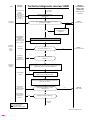
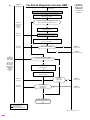
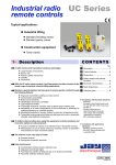
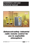
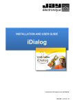
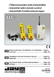
1
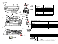
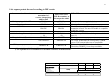
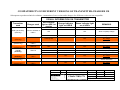
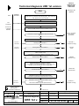
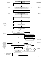
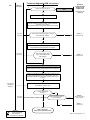
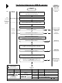
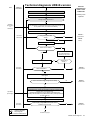
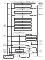
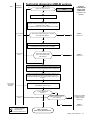
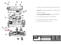
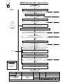
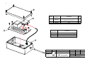
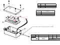
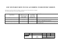
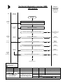
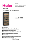
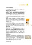
Repair data package
Industrial enhanced-safety
radio remote controls
UR Series
V1 - 02/2008 - English
électronique
Repair data package UR
- level 2
TABLE OF CONTENTS
•
PRODUCT INTERVENTION SHEET
SN 50 0010-00 EN
CHARGER URC
•
EVOLUTION OF CHARGER
SN 51 0010-00 EN
•
TEST OF CHARGER
SJ 51 0010-00 EN
TRANSMITTER URE
•
EXPLODED VIEW OF TRANSMITTER URE
SE 52 0010-00 EN
•
EXPLODED VIEW OF TRANSMITTER URE-B
SE 52 0020-00 EN
•
EVOLUTION OF TRANSMITTER URE
SN 52 0010-00 EN
•
COMPATIBILITY OF TRANSMITTER
AND CHARGER ACCORDING TO VERSION
SN 52 0020-00 EN
•
DIAGNOSTIC OF TRANSMITTER URE
SJ 52 0010-00 EN
•
DIAGNOSTIC OF TRANSMITTER URE-B
SJ 52 0020-00 EN
•
ASSEMBLY OF TRANSMITTER URE
SN 52 0030-00 EN
•
ASSEMBLY OF TRANSMITTER URE-B
SN 52 0040-00 EN
•
FINAL TEST OF TRANSMITTER AFTER REPAIR
SJ 52 0030-00 EN
RECEIVER URR
•
EXPLODED VIEW OF RECEIVER URR
SE 53 0010-00 EN
•
EXPLODED VIEW OF RECEIVER URR-B
SE 53 0020-00 EN
•
EVOLUTION OF RECEIVER URR
SN 530010-00 EN
•
DIAGNOSTIC OF RECEIVER URR - ALL VERSIONS
SJ 53 0010-00 EN
•
ASSEMBLY OF RECEIVER
SN 53 0020-00 EN
•
FINAL TEST OF RECEIVER
SJ 53 0020-00 EN
INSTALLATION AND USER MANUAL
Acknowledgement
of receipt
of documentation
électronique
UR Series
repair data package v.1
Industrial enhanced-safety
radio remote control
- level 2 First name :
Family name :
Company :
This will acknoledge receipt of the following document(s) :
• UR Series repair data package V1 02/2008
Date : _____________
Signature:
) Please fill in and return (or fax) to :
JAY Electronique, Eric DECHAME - service documentation
Address:
ZAC la Bâtie, rue Champrond F38334 St ISMIER CEDEX - FRANCE
Tel:
Fax:
+33.(0)4.76.41.44.00
+33.(0)4.76.41.44.44
e.mail : [email protected]
PRODUCT INTERVENTION SHEET - UR and UR-B
Intervention ref.:
ZAC la Bâtie, rue Champrond
F38334 SAINT ISMIER cedex
+33 (0)4 76 41 44 00 +33 (0)4 76 41 44 44
Diagnostic date:
E-mail : [email protected]
Web : Http://www.jay-electronique.fr
Repair date:
USER
INTERVENTION
Company / Contract:
Jay:
Address:
Intervening technician :
Tel.:
Fax:
Service station:
Tel.:
Fax:
Fault(s) indicated by user :
Information concerning intervention and invoicing
Type of intervention: REP: repair / REV : overhaul / MPR : Preventive maintenance / CRA: transformation.
Type of invoice: SG : covered by warranty / HG : not covered by warranty / SGR: covered by repair warranty.
Note: If intervention concerns upgrade of a functional sub-assembly (REV) or a transformation (TRA), enter code X99 in the part fault code boxes.
If the intervention concerns a missing part, tick the fault code X97 and fill in the designation for the corresponding sub-assembly.
Product returned compliant
For a product returned alone or a system (example: transmitter, receiver, …) checked out compliant, tick fault code X95 (line ZCONF1)
For a system (example: transmitter, receiver, …) for which only a part is compliant (example: transmitter), tick fault code X95 (line ZCONF2)
Product returned non-repairable
For a product returned which is not repairable, tick fault code X96 (line ZNOREP)
Result of transmitter diagnostic
URE
URE _
_
_
_
_
_
Intervention ref. :
Manufacturing date:
Serial No. / OF :
Date/reference of last repair :
Identity code:
Radio channel :
Dead man time:
Diagnostic date:
Repair date :
Type of intervention
Reference
Designation
(to be filled in)
Fault
code
PR0252
Housing assembly (base + cover) 4 PB config. without IR
PR0253
Housing assembly (base + cover) 4 PB config. with IR
PR0219
SEAL, TRANSMITTER HOUSING
PR0205
TRANSMITTER URE BATTERY 3.6V 370 MAH
PR0248
NEW LI-ION BATTERY FOR TRANSMITTER
PR0220E
TRANSMITTER RADIO MODULE version A
PR0254E
TRANSMITTER RADIO MODULE version B
PR0221___
MOTHERBOARD, CONFIG *** to be specified
PR0250___
NEW MOTHERBOARD, CONFIG *** to be specified
PR0057-BP
MECHANICAL KIT, 10 PB
PR0249COM
MECHANICAL KIT, 2 SELECTOR SWITCHES
URWE21V-B
ELECTRONIC KEY, NOT PROGRAMMED, version B
UWE202
SHEET WITH 6 BUTTON LABELS, COLOR ARROWS
UWE207
SHEET WITH 90 BUTTON LABELS, BLACK AND WHITE
URCUi
230V- 9VDC INDUSTRIAL CHARGER
URCi-B
URE CHARGER version B
UCCU
Adapter, 230VAC EUROPE / 5 VDC
UCC1
Adapter, 24VDC-6VDC for vehicle
UCC4
Adapter, 24VAC/DC-5VDC DIN
URE2__0-B
COMPLETE PRODUCT, version B (specify button configuration)
URE3__0-B
COMPLETE IR product, version B (specify button configuration)
REP
REV
MP
Type of invoice
TRA
SG
HG
SGR
Price (taxes not
incl.)
Labor
Sub-total (taxes
not incl.)
Result of receiver diagnostic
URR
Manufacturing date:
Serial No. / OF :
Date/reference of last repair :
URR _
_
_
_
Additional ref. : _
_
Identity code:
Radio channel :
Type of intervention
Reference
_
Fault
code
Designation
REP
REV
MP
TRA
Type of invoice
SG
HG
SGR
Price (taxes not
incl.)
(to be filled in) HOUSING ASSEMBLY
PR0225C__
URR MOTHERBOARD (specify voltage)
PR0237R
URR TUNER
PR0123
RECEIVER FUSE KIT
UDF1
1 IR MODULE KIT + 10 METRES OF CABLE
VUB084
1/4 WAVE STRAIGHT ANTENNA, 433-434 MHZ
VUB105
ANTENNA EXTENDER, 2M+BRACKET, NOT INSULATED
VUB125
ANTENNA EXTENDER, 5M+BRACKET, NOT INSULATED
OWR01
PLUG-IN ANTENNA BNC KIT
Labor
Sub-total (taxes
not incl.)
Last update on 02/08
JAY ELECTRONIQUE
SN 50 0010-00 EN
1/1
EVOLUTION OF CHARGER UR
Key-type charger
Note : Incompatible with transmitter URE-B
URC1 (24VDC-> 9VDC charger)
URCU (230VAC– 9VDC charger with European plug)
URCW (230VAC– 9VDC charger with UK plug)
Marketing discontinued : 2006
Product no longer available for maintenance.
Industrial charger (1st version)
URC1i (24VDC-> 9VDC charger)
URCUi (230VAC – 9VDC charger Euro. plug)
URCWi (230VAC – 9VDC charger UK plug)
First marketed : April 04.
Marketing discontinued : February 07
Availability for maintenance : contact us.
Only transmitters (URE) with manufacturing data file ref. greater than or equal to A004 can be used with
this charger. Otherwise, the transmitter software must be updated (return to factory).
The URE-B units cannot be used with this charger.
Industrial charger version B
URCi-B (Charger)
UCCU (230V-5VDC adapter with Euro plug)
UCCW (230V-5VDC adapter with UK plug)
UCC1 (24V-6VDC vehicle adapter)
UCC4 (24VDC-5VDC din rail adapter)
First marketed : February 07
Only transmitters (URE-B) can be used with this charger. The battery charger voltage is 5VDC (6VDC
max.) instead of 9VDC.
Indice
N° Modif
Modifications
Nom
date
Vérifié par
0
T607
Création du document
A.PO RTAZ
2 9/0 3/ 20 07
B.CH ACO RN AC
EVOLUTION OF CHARGER UR
Format : A4
électronique
ZAC la Bati e S ai nnt Ismi er
Té l : 04.7 6.41.44 .00
Té léc opi e : 0 4.76.41.44.41
URC
Loc doc :
Réf :SN 51 0010-00 EN
c e do cum en t e st no tre prop rié té, sa ns au to risa ti on form ell e, il n ed oi t p as être re pro du it, co pié o u com muni qué à de s ti ers
1/2
CHECK OF INDUSTRIAL CHARGER (1st version)
Charger reference (1st version /April 04 to February 07)
URCUI 230VAC- 9VDC (European plug)
URCWI : 230VAC- 9VDC (UK plug)
URC1I : 12-24VDC- 9VDC (cigarette lighter).
Note : The charger and power supply unit (9VDC output) cannot be dissociated.
Caution :
Voltage:9 VDC
+ :- 10%
-
+
Indice
N° Modif
Modifications
Nom
date
Vérifié par
0
T607
Création du document
A.PORTAZ
2 9/ 02 /200 7
B.C HAC ORNAC
Check of charger
Format : A4
électronique
ZAC la BAT IE
38334 Sa int I smi er
Té l : 04.7 6.41.44 .00
Té léc opi e : 0 4.76.41.44.44
URC
Loc doc :
Réf :SJ 50 0010-00
c e docum en t e st n otre pro prié té, sans a utorisa tion form el le , il n edoi t p as être re p ro du it, co pié ou com mun iqué à des tie rs
2/2
CHECK OF INDUSTRIAL CHARGER - VERSION B
Reference of charger version B (as of February 07)
Charger URCI-B + power supply unit UCCU 230VAC-5VDC (European plug)
Charger URCI-B + power supply unit UCCW 230VAC-5VDC (UK plug)
Charger URCI-B + power supply unit UCC1 24VDC-6VDC (cigarette lighter input)
Charger URCI-B + power supply unit UCC4 24VDC-5VDC (screw terminal input)
Caution : Voltage : 5
VDC or 6V DC + :10%
+
Charger ref. URCI-B
+
-
Ex : 230V-5VDC
adapter ref. UCCU
Indice
N° Modif
Modifications
Nom
date
Vérifié par
0
T607
Création du document
A.PORTAZ
2 9/ 02 /200 7
B.C HAC ORNAC
Check of charger
Format : A4
électronique
ZAC la BAT IE
38334 Sa int I smi er
Té l : 04.7 6.41.44 .00
Té léc opi e : 0 4.76.41.44.44
URC
Loc doc :
Réf :SJ 50 0010-00
c e docum en t e st n otre pro prié té, sans a utorisa tion form el le , il n edoi t p as être re p ro du it, co pié ou com mun iqué à des tie rs
1
Item
1à 9
2
8
11
PR0220E (2)
PR0205 (2)
PR0221 ***(2)
Transmitter housing seal
HF module
ni-mh battery
Motherboard (specify version)
Mechanical kit, 10 PB + on
PR0057 BP
Not referenced
Rotary switch
(3)
URWE21V (1) URE key, not programmed
UWE207
13
14
Housing equipped with 4 Pushbutton with IR
10
14
16
12
Housing equipped with 4 Pushbutton
PR02281**(1)
PR0219
15
Designation
PR02280** (1)
3
7
11
10
PR
Button labels kit
(1) No longer available
(2) Available up to termination of stock
(3) Not available. See document SN 520010
9
3
Specify motherboard reference
Spare part
4
reference
5
PR022101C
Designation
Remark
URE Mother board CONFIG.1C
PR0221011
URE Mother board CONFIG.11
PR022102C
URE Mother board CONFIG.2C
PR0221022
URE Mother board CONFIG.22
PR0221122
URE Mother board CONFIG.22 IR
Motherboards with rotary switches
: no longer available
15
6
16
7
Indice
N° Modif
0
T607
électronique
ZAC la Batie
38334 St Ismier
Tél : 04.7 6.41.44 .00
Modifications
Nom
Date
Vérifié par
Création du document
A.PORTAZ
29.03.07
B.CHACORNAC
Transmitter exploded view
Format : A4
URE 1st Version
Loc doc :
Réf : SE 520010-00
Téléc opie : 0 4.76.41.44.44
c e document est notre propriété, sans autorisation formelle, il n edoit pas être reprodu it, co pié ou communiqué à des tiers
3
8
Item
9
Designation
Housing equipped with 4 PB
2
PR0253
PR0219
Housing equipped with 4 PB with IR
URE transmitter housing seal
4
PR0254E
HF Module
1+2+3 + 7+11 to 14
10
5
PR
PR0252
4
5
PR0248
Battery
6
PR02502 **
PR0057BP
Mother board (specify version)
Mechanical kit, 10 PB + on
8 to 12
PR0249 COM
URWE21-B
Mechanical kit 2 rotary switches
URE key, programmed (specify key No.)
URWE21V-B
UWE207
URE key, not programmed
Button labels kit
15
11
12
6
13
Specify motherboard reference
Spare part
Designation
Remark
URE-B MOTHERBOARD
Specify button configuration, see
sales manual E730
PR0250211
TO BE CONFIGURED
URE-B MOTHERBOARD CONFIG.11
PR0250222
URE-B MOTHERBOARD CONFIG.22
PR025022C
URE-B MOTHERBOARD CONFIG.2C
URE-B MOTHERBOARD
Specify button configuration, see
TO BE CONFIGURED
sales manual E730
reference
PR02502**
2
PR02503**
14
1
7
15
Indice
N° Modif
0
T607
électronique
ZAC la batie
38334 Sa int Ismier
Tél : 04.7 6.41.44 .00
Modifications
Nom
Date
Vérifié par
Création du document
A.PORTAZ
29.03.07
B.CHACORNAC
Transmitter exploded view
Format : A4
URE-B
Loc doc :
Réf : SJ 52 0020-00
Téléc opie : 0 4.76.41.44.44
ce docum ent est no tre propriété, sans au to risati on formelle, il n edoit pas être reprodu it, copié ou communi qué à des tiers
1/2
EVOLUTION OF TRANSMITTER
Subsequent to product technical evolutions, certain spare parts have changed.
Indicated below are the various spare parts to be used.
Presentation of transmitter URE-B
New emergency
stop palmswitch
Orange LED
New electronic key
Rotary switches (new design), only on second row
Indice
N° Modif
Modifications
Nom
date
Vérifié par
0
T607
Création du document
A.PORTAZ
29/03/2007
B.CHACORNAC
é le c tro n iq ue
Transmitter evolution
URE
Format : A4
Loc doc :
ZAC la batie
38334 St Ismier
Tél : 04.76.41.44.00
Télécopie : 04.76.41.44.44
ce document est notre propriété, sans autorisation formelle, il n edoit pas être reproduit, copié ou communiqué à des tiers
Réf :SN 52 0010-00
2/2
List of spare parts to be used according to URE version
Spare part sales designation
Housing equipped with 4 PB
Parts to be used if URE
transmitter 1st°
version, data package
A001 to A007
PR0252
PR0253 (IR)
PR0219
Parts to be used if
URE-B transmitter as
of data package A001
REMARKS
PR0252
PRO253 (IR)
PR0219
If rotary switches are required, housing must be customized
using rotary switch kit PR0249COM.
Housing seal
No change
HF Module
The old versions of the HF module are available up to
PR0220E
PR0254E
termination of stock. The new HF module is compatible
with all the versions
Battery
PR0205 (nimh)
PR0248 (lithium ion) Battery PR0205 (Ni-Mh) PR0248 (lithium-ion). (1)
Motherboard (specify version)
PR0221***
PR0250***
The old battery PR0205 is available up to termination of
(2)
(2)
stock (1).
Mechanical kit (10 BP + On)
PR0057BP
PR0057BP
No change
Rotary switch kit
In case of a rotary switch fault (mechanical part) on a URE
Not referenced
PR0249COM
1st version, product must be exchanged by a URE-B
version. The rotary switches are not compatible.
URE key, not programmed
This new key is compatible with all the versions.
URWE21V-B
URWE21V-B
The old key URWE21V is no longer available.
(1) Beyond this availability, it will be necessary to replace the transmitter and charger by a version « B »
(2) See exploded views of transmitters to determine references of motherboards.
Indice
N° Modif
Modifications
Nom
date
Vérifié par
0
T607
Création du document
A.PORTAZ
29/03/2007
B.CHACORNAC
é le c tro n iq ue
Transmitter evolution
URE
Format : A4
Loc doc :
ZAC la batie
38334 St Ismier
Tél : 04.76.41.44.00
Télécopie : 04.76.41.44.44
ce document est notre propriété, sans autorisation formelle, il n edoit pas être reproduit, copié ou communiqué à des tiers
Réf :SN 52 0010-00
COMPATIBILITY OF DIFFERENT VERSIONS OF TRANSMITTER-CHARGER UR
Subsequent to product technical evolutions, a transmitter of one version and a charger of a different version are not compatible.
VISUAL INFORMATION ON TRANSMITTER
Transmitter
used
URE (1st version)
(with key)
URE (1st version)
(with key)
URE
(without key)
URE (1st version)
(without key)
URE-B
(with key)
URE-B
(with key)
URE-B
(without key)
URE-B
(without key)
Red indicator
light on URE 1st
version
Green indicator light
on all UREs
REMARKS
ON
Flashing
Fast charge
ON
ON
Slow or upkeep charge
2 flashes
2 flashes
Charge fault
Flashing fast
OFF
No charge
URCUI or URCWI or
URC1i
OFF
OFF
Slow charge without indication
URCI-B
OFF
OFF
No charge
Charger used
URCUI or URCWI or
URC1i
Orange indicator
light on URE-B
URCI-B
URCI-B
ON
ON
2 flashes
Flashing
ON
2 flashes
Fast charge
Slow or upkeep charge
Charge fault
URCUI or URCWI or
URC1i
OFF
OFF
No charge
URCI-B
OFF
OFF
Fast charge then slow charge
without indication
URCUI or URCWI or
URC1i
OFF
OFF
No charge
Indice
N° Modif
Modifications
0
T607
Création du document
électronique
ZAC la Bati e
38334 St Ismi er
Té l : 04.7 6.41.44 .00
Té léc opi e : 0 4.76.41.44.44
COMPATIBILITY
Nom
date
Vérifié par
A.PORTAZ
29/03/2007
B.CHACORNAC
Format : A4
Loc doc :
TRANSM ITT ER-C HARGER Réf :SN 50 0020-00
ce doc ume nt est notre p ropri été , san s a utori sa tio n f orme lle , il n e doit pa s ê tre rep roduit, copi é ou co mmu niq ué à de s tie rs
Tool
Technical diagnosis URE 1st version
PRODUCT
INTERVENTION
SHEET TO BE
COMPLETED
Start
sub-assy to be
replaced
Additional
information
- On the intervention sheet, write down the URE sales reference
- Read electronic parameters and following data : radio channel, ID
code, "Dead man" function duration
Visual inspection of URE
Flat
screwdriver
Open the transmitter and separate the half-shells.
Tool P01570
+ DialogUR
Software
Check the URE version and internal software revision
Transmitter complies with respect to technical changes
table ?
See doc : Evolution
of transmitter
SN 520010
no
yes
Check for absence of grime or cracks on the half-shells
Document
SN 520030
Housing in good condition ?
no
PR 0228 ***
(complete housing)
no
PR 0219
(seal)
yes
Document
SN 520030
Housing seal in good condition ?
yes
Visual inspection of electronic key :
Check condition of key;
check that key is securely engaged in transmitter cover
Electronic key in good condition ?
URWE21
(URE elec. key)
no
yes
Check of function and "On/horn" buttons :
Check condition of the capsules (tightness), push-in and rotary
operation (check for automatic return, if applicable).
Function buttons in good condition ?
PR0057 BP
Mechanical kit
no
yes
Mechanical check of stop palmswitch button
Check that stop palmswitch locks and unlocks correctly
Document
SN 520030
Palmswitch mechanism in good condition ? (Pin,
mushroom)
Also check condition of green capsule and ring
Symbols :
: Continue diagnosis
: Stop diagnosis
M.P. : Preventive maintenance
PR 0228 ***
(complete housing)
no
yes
continued on 2
Indice
N° de modif:
Modification
Nom
Date
Approuvé par:
00
T001
Modification
JM.Bormann
29/03/2007
B.Chacornac
Format:
A4
B P 5 - 17 6 , r u e L a v oi si e r
M ON T B ON N OT - S t M A R TI N - 3 8 3 3 4 S t I S M I ER
C ED EX
T él: 0 4 .76 .4 1. 4 4 .0 0
F ax: 0 4 . 76 . 4 1.4 4 . 4 4
Technical diagnosis
URE 1st v.
Nom du fichier:
REF DOC:
SJ 52 0010-00
Page:
1/4
Ce docum ent est notre propriété, sans notre autorisation form elle, il ne doit pas être reproduit, copié ou com m uniqué à des tiers.
Technical diagnosis URE 1st version
Tool
Additional
information
PRODUCT
INTERVENTION
SHEET TO BE
COMPLETED
From page 1
Functional check of URE transmitter
sub-assy to be
replaced
Unlock the transmitter stop palmswitch button
See table of
possible fault
causes in
installation
manual
yes
Red and green leds flash simultaneously ?
no
no
Red and green leds off ?
yes
Stabilized
power supply
Or
Test battery
Lock palmswitch on transmitter and supply it with power supply set
for 4V (100mA min.) or connect a test battery.
Unlock the transmitter stop palmswitch button
Document
SN 520030
Red and green leds still off ?
PR0221 ***
Motherboard
yes
no
PR0205
Battery
Continue with a test battery
Green led on steady ?
no
yes
Lock and unlock transmitter
stop palmswitch button
observing a stop period
Press the "ON" button after 15s
Document
SN 520030
yes
Green led on
steady ?
Green led flashes ?
PR0221 ***
Motherboard
no
yes
Stop transmitter and connect a test URCU to check if charging takes
place.
Green Led flashes and red led on steady ?
no
PR0221 ***
Motherboard
yes
Test of "battery charge" detection thresholds
If not already done, supply the transmitter using the variable power
supply set for 4V (100mA mini).
Gradually decrease the supply voltage while locking then unlocking the
transmitter stop palmswitch button (check performed on each start-up).
Adjustable
power supply
Decrease the voltage until the red led flashes slowly
Document
SN 520030
Symbols :
: Continue diagnosis
: Stop diagnosis
M.P. : Preventive maintenance
Power supply voltage measured in this case is
between 3,6V and 3,8V
no
PR0221 ***
Motherboard
yes
Continued
on page 3
URE 1st version diagnosis
2/4
Technical diagnosis URE 1st version
Tool
PRODUCT
INTERVENTION
SHEET TO BE
COMPLETED
From page 2
Additional
information
Lower the voltage until the red led flashes rapidly.
sub-assy to be
replaced
Document
SN 520030
Power supply voltage measured in this case is
between 3,3 and 3,5 V
PR0221 ***
Motherboard
no
yes
Decrease the voltage again until the red and green leds go off
Document
SN 520030
Power supply voltage is under
< 3.2V
PR0221 ***
Motherboard
no
yes
Radio module check
Use the charged battery or connect a stabilized power supply
set for 4V to the motherboard
Use the test URR receiver
Software
"DialogUR"
+ programming
tool bench
P01533
Program an electronic key with receiver parameters (same ID
code and same radio channel)
Unlock the transmitter stop palmswitch button
and press the "on" button
Green led on radio receiver on steady
? (place transmitter as far away as
possible)
no
Test radio
module
ref: PR0220 E
Install the transmitter test radio
module in place of the radio module
Unlock the transmitter stop palmswitch
button
and press the "on" button
yes
Green led on radio
receiver on steady ?
Document
SN 520030
Jay
Electronique
special test
instrumentation
In the case of
the use of the
tool P01570 +
DialogUR, The
radio quality
must be
superior to
90 %
yes
PR0221 ***
Motherboard
no
Do you have the means to measure
the radio module characteristics?
Document
SN 520030
no
Radio module
more than 5 y old?
yes
yes
no
Test radio module
using test bench
Radio module
performance sufficient?
Symbols :
: Continue diagnosis
: Stop diagnosis
M.P. : Preventive maintenance
PR0220 E
Transmitter radio
module
Customer has
reported
transmission
cutouts?
yes
PR0220 E
Transmitter radio
module
no
yes
no
Continued on page 4
URE 1st version diagnosis
3/4
Technical diagnosis URE 1st version
Tool
Additional
information
From page 3
no
Check of the IR start-up
option
IR start-up option present?
PRODUCT
INTERVENTION
SHEET TO BE
COMPLETED
sub-assy to be
replaced
yes
Connect the test IR module to the test receiver
Program receiver according to URE, unlock palmswitch
and press « On » button.
Point URE at test UDF with minimum distance of 3 meters.
Document
SN 520030
Test receiver safety relays pull in and red
led of test UDF flashes?
PR0221 1**
IR Motherboard
no
yes
Test a range of 10 meters
Repeat the transmitter start-up procedure (lock, unlock
stop palmswitch button and press "on" button)
Document
SN 520030
Test receiver safety relays
pull in and red led of test
UDF flashes?
PR0221 1**
IR Motherboard
no
yes
Check of button states
Use test receiver and program the button/relay
correspondence according to transmitter button configuration
Unlock the transmitter stop palmswitch button, press the "on"
button and actuate the function buttons one by one (1st,
2nd speed for BPDV) and any rotary switches which may be
present.
Tool P01570
+ DialogUR
Software
Check that actions on transmitter buttons/switches are
transmitted to receiver relays
Actions transmitted
correctly ?
no
Button mechanical part in
good condition?
Document
SN 520030
no
PR0057 x
Mechanical kit PB or
Rotary switches
yes
yes
Symbols :
: Continue diagnosis
: Stop diagnosis
M.P. : Preventive maintenance
PR0221 ***
Motherboard
END of diagnosis.
After repair, perform final test
URE 1st version diagnosis
4/4
Technical diagnosis URE-B version
PRODUCT
INTERVENTION
SHEET TO BE
COMPLETED
START
Additional
information
Tool
sub-assy to be
replaced
- On the intervention sheet, write down the URE sales reference
- Read electronic parameters and following data : radio channel, ID
code, "Dead man" function duration
Visual inspection of URE
Flat
screwdriver
Open the transmitter and separate the half-shells.
Tool P01570
+ DialogUR
Software
Check the URE version and internal software revision
Check for absence of grime or cracks on the half-shells
Document
SN 520040
Housing in good condition ?
no
PR 0252 or PR0253
(complete housing)
+ PR0249 COM
(switch kit)
no
PR 0219
(Housing seal)
yes
Document
SN 520040
Housing seal in good condition ?
yes
Visual inspection of electronic key :
Check condition of key;
check that key is securely engaged in transmitter cover
Electronic key in good condition ?
URWE21V-B
(URE elec key)
no
yes
Check of function and "On/horn" buttons :
Check condition of the capsules (tightness), push-in and rotary
operation (check for automatic return, if applicable).
Function buttons in good condition ?
PR0057 BP
PR0249 COM
Mechanical kit
no
yes
Mechanical check of stop palmswitch button
Check that stop palmswitch locks and unlocks correctly
Palmswitch mechanism in good condition ? (Pin,
mushroom)
Also check condition of green capsule and ring
PR0227 (Kit stop
palmswitch button)
+ capsule 319241 +
ring 323260
no
yes
Symbols :
: Continue diagnosis
: Stop diagnosis
M.P. : Preventive maintenance
Continued on
page 2
01
T607
Evolution UR version B
JM. BORMAN
19/02/2007
B.CHACORNAC
Indice
N° de modif:
Modification
Nom
Date
Approuvé par:
00
T001
Création
D.PARAT
22/03/2004
Format:
A4
Technical diagnosis
ZA C l a B a t i e 3 8 3 3 4
S t I S M I ER C ED EX
T él : 0 4 . 76 . 4 1. 4 4 .0 0
F ax: 0 4 . 76 . 4 1. 4 4 .4 4
URE-B
Nom du fichier:
version
REF DOC:
SJ 52 0020-00
Page:
1/4
Ce docum ent est notre propriété, sans notre autorisation form elle, il ne doit pas être reproduit, copié ou com m uniqué à des tiers.
Technical diagnosis URE-B version
Tool
Additional
information
PRODUCT
INTERVENTION
SHEET TO BE
COMPLETED
From page 2
Functional check of URE transmitter
sub-assy to be
replaced
Unlock the transmitter stop palmswitch button
no
Orange and green leds off ?
yes
Stabilized
power supply
Or
Test battery
Lock palmswitch on transmitter and supply it with power supply set
for 4V (100mA min.) or connect a test battery.
Unlock the transmitter stop palmswitch button
Document
SN 520040
Orange and green leds
still off ?
PR0250***
Motherboard
yes
PR0248
Battery
no
Continue with a test battery
Green led on steady ?
no
Lock and unlock transmitter
stop palmswitch button
observing a stop period
yes
Press the "ON" button after 15s
Document
SN 520040
yes
Green led on
steady ?
Green led flashes ?
PR0250***
Motherboard
no
yes
Stop transmitter and connect a test charger to check if charging
takes place.
Green Led flashes and Orange led on steady
?
no
PR0250***
Motherboard
no
PR0250***
Motherboard
yes
Test of "battery charge" detection thresholds
If not already done, supply the transmitter using the variable power
supply set for 4V (100mA mini).
Gradually decrease the supply voltage while locking then
unlocking the transmitter stop palmswitch button (check performed
on each start-up).
Adjustable
power supply
Decrease the voltage until the red led flashes slowly
Document
SN 520040
Symbols :
: Continue diagnosis
: Stop diagnosis
M.P. : Preventive maintenance
Power supply voltage measured in this case is
between 3,6V and 3,8V
yes
Continued on page 3
URE-B version diagnosis
2/4
Technical diagnosis URE-B version
Tool
Additional
information
PRODUCT
INTERVENTION
SHEET TO BE
COMPLETED
From page 2
Lower the voltage until the Orange led flashes rapidly.
Document
SN 520040
Power supply voltage measured in this case is
between 3,3 and 3,5 V
sub-assy to be
replaced
PR02501** confb 15
Motherboard
no
yes
Decrease the voltage again until the Orange and green leds
go off
Document
SN 520040
Power supply voltage is under
< 3.2V
PR02501** confb 15
Motherboard
no
yes
Radio module check
Use the charged battery or connect a stabilized power supply
set for 4V to the motherboard
Use the test URR receiver
Software
"DialogUR"
+ programming
tool bench
P01533
Program an electronic key with receiver parameters (same ID
code and same radio channel)
Unlock the transmitter stop palmswitch button
and press the "on" button
Green led on radio receiver on steady
? (place transmitter as far away as
possible)
no
Test radio
module
ref: PR0254 E
Install the transmitter test radio
module in place of the radio module
Unlock the transmitter stop palmswitch
button and press the "on" button
yes
Receiver’s green led is on
steady ?
Document
SN 520040
Jay
Electronique
special test
instrumentation
yes
PR0250***
Motherboard
no
Do you have the means to measure
the radio module characteristics?
Document
SN 520040
In the case of
the use of the
tool P01570 +
DialogUR, The
radio quality
must be
superior to
90 %
Symbols :
: Continue diagnosis
: Stop diagnosis
M.P. : Preventive maintenance
PR0254 E
Transmitter radio
module
no
Radio module
more than 5 y old?
yes
yes
no
Test radio module
using test bench
Radio module
performance sufficient?
Customer has
reported
transmission
cutouts?
yes
PR0254 E
Transmitter radio
module
no
yes
Continued on page 4
non
URE-B version diagnosis
3/4
Technical diagnosis URE-B version
Tool
Additional
information
From page 3
no
Check of the IR start-up
option
IR start-up option present?
yes
PRODUCT
INTERVENTION
SHEET TO BE
COMPLETED
sub-assy to be
replaced
Connect the test IR module to the test receiver
Program receiver according to URE, unlock palmswitch
and press « On » button.
Point URE at test UDF with minimum distance of 3 meters.
Document SN
520040
Test receiver safety relays pull in and red
led of test UDF flashes?
PR0250***
Motherboard
no
yes
Test a range of 10 meters
Repeat the transmitter start-up procedure (lock, unlock
stop palmswitch button and press "on" button)
Document SN
520040
Test receiver safety relays
pull in and red led of test
UDF flashes?
PR0250***
Motherboard
no
yes
Check of button states
Use test receiver and program the button/relay
correspondence according to transmitter button configuration
Unlock the transmitter stop palmswitch button, press the "on"
button and actuate the function buttons one by one (1st,
2nd speed for BPDV) and any rotary switches which may be
present.
Tool P01570
+ DialogUR
Software
Check that actions on transmitter buttons/switches are
transmitted to receiver relays
Actions transmitted
correctly ?
no
Button mechanical part in
good condition?
Document SN
520040
no
PR 0252 ou PR0253
(complete housing)
+ PR0249 COM
(switch kit)
yes
yes
Symbols :
: Continue diagnosis
: Stop diagnosis
M.P. : Preventive maintenance
PR0250***
Motherboard
END of diagnosis.
After repair, perform final test
URE-B version diagnosis
4/4
7
4
5
8
1-
Configure cover of housing (1) by adding rotary switches if necessary
2-
Insert motherboard (2) by lifting seal as shown in drawing. Secure with
screw (3).
3-
Connect the HF module (4).
4-
If it is a new HF module « PR0254E », glue foam (8) supplied with
module to housing base in order to block it.
3
5-
2
9
Connect the battery (5) and position it on the motherboard.
6-
Position the fastener (6) by passing it through shackle ring (9).
7-
Close the housing and secure it with screws (7)
6
1
Référence
N° Modif
Modifications
Nom
SN520030-00
T607
Création du document
A.PORTAZ
électronique
ZAC la Batie
38334 St Ismier
Tél : 04.7 6.41.44 .00
Téléc opie : 0 4.76.41.44.44
Transmitter assembly
URE 1st version
Date
Vérifié par
29/03/2007 B.CHACORNAC
Format : A4
Loc doc :
Réf : SN 520030-00
ce doc ument est notre propri été, sans autorisatio n formelle, il n edoit pas être reproduit, copié ou communiq ué à des tiers
7
Configure cover of housing (1) by adding rotary switches if necessary.
2-
Insert motherboard (2) by lifting seal as shown in drawing. Secure with
screw (3).
3-
Connect the HF module (4).
4-
Connect the battery (5) and position it on the HF module.
5-
4
5
1-
Close the housing and secure it with screws (7).
3
2
6
1
Référence
N° Modif
Modifications
Nom
SN520040-00
T607
Création du document
A.PORTAZ
Transmitter assembly
Format : A4
électronique
ZAC la batie
38334 St Ismier
Tél : 04.7 6.41.44 .00
Téléc opie : 0 4.76.41.44.44
URE-B
Date
Vérifié par
29/03/2007 B.CHACORNAC
Loc doc :
Réf : SN 52 0040-00
ce doc ument est notre propri été, sans autorisatio n formelle, il n edoit pas être reproduit, copié ou communiq ué à des tiers
URE final test after intervention
START
Unlock the stop palmswitch button
Additional
information
Transmitter green led comes on steady?
no
yes
Press transmitter "on" button
Transmitter green led flashes?
no
yes
Press transmitter stop palmswitch button
Tools :
Green led goes off?
no
yes
Test receiver
Install test key configured with test receiver parameters on URE unit
or program test receiver according to URE
Test elec key
Test tool P01570
DialogUR
software
Unlock the stop palmswitch button and press "on" button
Receiver’s green led is « on » steady ?
no
yes
Safety and horn relays pull in
when transmitter "on" button is pressed?
no
yes
Actuate the function buttons or switches one by one
All actions transmitted?
no
yes
no
IR start-up option present ?
yes
Equip the test receiver with a UDF and program it as follows:
IR start-up option
Test UDF
Press green "on" button while pointing the URE toward the test
receiver (3m min. distance between URE and UDF)
Receiver safety and horn relays pull in ?
Key :
no
yes
no
Press the stop palmswitch button
=
Test is negative, repeat
technical diagnosis on
product
Fill in the repair labels and fasten them to the transmitter,
then fill in the intervention sheet
END
Indice
N° de modif:
Modification
00
T 607
Création
Nom
JM.BORMANN 29/03/2007
Format:
ZAC l a ba t i e
3 8 3 3 4 S t I S M I ER C ED EX
T él: 0 4 .76 .4 1.4 4 .0 0
F ax: 0 4 .76 .4 1.4 4 .4 4
Transmitter final test
URE
Date
Nom du fichier:
REF DOC:
Approuvé par:
B.CHACORNAC
A4
\dossier UR\dossier rep\ure\final
SJ 520030-00
Page:
1/1
Ce docum ent est notre propriété, sans notre autorisation form elle, il ne doit pas être reproduit, copié ou com m uniqué à des tiers.
2
Item
3
1
Spare part
Description
reference
PR0225**
Qty
URR motherboard
1
(specify voltage version)
2
PR0226
Housing assembly
1
3
PR0224R
tuner
1
1
Spare part
reference
Description
PR0225C4
URR MOTHERBOARD 3+6RL
12-24VDC
PR0225CA
URR MOTHERBOARD 3+6RL
24-48VAC
PR0225CB
URR MOTHERBOARD 3+6RL 115-230VAC
Only motherboards with 6 function relays are available
2
Référence
N° Modif
Modifications
Nom
date
Vérifié par
SE 530010
T607
Création du document
A.PORTAZ
29/03/2007
B.CHACORNAC
électronique
ZAC la batie
38334 la Batie
Tél : 04.7 6.41.44 .00
Téléc opie : 0 4.76.41.44.44
Receiver exploded view
URR 1st version
Format : A4
Loc doc :
Réf :SE 53 0010-00
c e document est no tre propriété, sans au torisation form elle, il n edoit pas être repro du it, copié o u com muniqué à des tiers
Item
PR
Description
1
PR0225**
URR Motherboard (specify version)
2
PR0226
Housing assembly
3
PR0237R
Tuner
2
Detai ls on motherboard reference
Spare part
Description
reference
PR0225C4
URR M OTHERBOARD 3+6RL
12-24VDC
PR0225CA
URR MOTHERBOARD 3+6RL
24-48VAC
PR0225CB
URR MOTHERBOARD 3+6RL 115-230VAC
Only motherboards w i th 6 functi on relays are av ai lable
3
1
Fixed antenna or BNC kit for plug-in antenna ref. OWR01
2
Référence
N° Modif
électronique
ZAC la Batie
38334 St Ismier
Tél : 04.7 6.41.44 .00
Téléc opie : 0 4.76.41.44.44
Modifications
Nom
date
Vérifié par
Création du document
A.PORTAZ
29/03/2007
B.CHACORNAC
Transmitter exploded view
Format : A4
URR-B
Loc doc :
Réf : SE 530020-00
c e document est notre propriété, sans autorisation formelle, il n edoit pas être reprodu it, co pié ou communiqué à des tiers
LIST OF SPARE PARTS TO USE ACCORDING TO RECEIVER VERSION
Subsequent to product technical evolutions, certain spare parts of the product have changed.
The various spare parts to be used are indicated below.
Sales designation
of spare parts
URR motherboard
Parts to be used with
URR receiver 1st
version, data package
A001 to A003
PR0225**
Parts to be used
with URR-B
receiver, data
package A001
PR0225**
Tuner
PR0237R
PR0237R
Housing assembly
PR0226
PR0226
REMARKS
Only motherboards with 6 function relays are available
The new tuner is compatible with the old and new receiver.
The tuner ref. PR0208R is discontinued.
The rubber wire grommets have been replaced by plastic
cable glands (PE).
Indice
N° Modif
Modifications
Nom
date
Vérifié par
0
T607
Création du document
A.PORTAZ
2 9/ 03 /200 7
B.CH ACORNAC
Evolution of receiver
Format : A4
électronique
ZAC la Bati e
38334 St Ismi er
Té l : 04.7 6.41.44 .00
Té léc opi e : 0 4.76.41.44.44
URR
Loc doc :
Réf :SN 530010-00
c e do cum en t e st no tre prop rié té, sa ns au to risa ti on form ell e, il n edoi t p as être re pro du it, co pié o u com muni qué à de s ti ers
Technical diagnosis receiver URR
All version
PRODUCT
INTERVENTION
SHEET TO BE
COMPLETED
sub-assy to be
replaced
Additional
information
Tool
START
Visual inspection of UDR
POZIDRIV
screwdriver
No. 2
Open the receiver housing
See "Receiver
changes"
document
Check the receiver version
Receiver complies with respect to technical changes
table?
******
Spare part or technical
upgrade accessory
(M.P.)
no
yes
POZIDRIV
screwdriver
No. 2
Document
NN 695100
Housing in good condition?
no
PR0226
Receiver housing
no
UDF 1 / 2
PR0133
IR Module (M.P.)
no
PR0226
Receiver housing
yes
PR0225 **
Motherboard (M.P.)
no
PR0225 **
Motherboard (M.P.)
yes
Torx n°10
screwdriver
If present, IR modules in good condition?
yes
If present, plug-in connectors in good condition?
yes
Document
NN 695100
- POZIDRIV
screwdriver
No. 2
-flat nose pliers
Receiver motherboard oxidised or modified by third party?
no
Spring terminal boards in good condition?
yes
Continued on page 2
Symbols/abbreviations :
: Continue Diagnosis
: Stop Diagnosis
P.M. : Preventive Maintenance
SJ 530010-00
T607
Mise à jour version UR-B
Indice
N° de modif:
Modification
Nom
Date
NON CODIFIE
T001
Création
D,PARAT
19/03/2004
Format:
A4
ZAC l a Ba t i e
3 8 3 3 4 S t I S M I ER C ED EX
T él: 0 4 .76 .4 1.4 4 .0 0
F ax: 0 4 .76 .4 1.4 4 .4 4
URR (all version)
Technical diagnosis
JM BORMANN 29/03/2007
Nom du fichier:
REF DOC:
B.CHACORNAC
Approuvé par:
\dossierUR\reparation\diagnostics
REF
SJ 530010-00
Page:
1/5
Ce docum ent est notre propriété, sans notre autorisation form elle, il ne doit pas être reproduit, copié ou com m uniqué à des tiers.
Tool
Additional
information
Technical diagnosis receiver URR
Continued
from page 1
Power supply fuse
ratings:
24/48VAC
F1=0.8A, F2=1.6A
115/230VAC
F1=0.16A, F2=0.315A
12/24VDC
F1=1A, F2=1A
sub-assy to be
replaced
Check of power supply fuses
continuity test
Fuses in good condition and compliant with respect to
power supply voltage?
6mm flat tip
screwdriver
Pay attention to
power supply
voltage.
If necessary, equip
receiver with a test
UDF IR module
no
PR0123
Receiver fuse kit
Replace fuses for
subsequent part of
diagnosis
yes
-POZIDRIV
screwdriver
No. 2
- flat nose
pliers
PRODUCT
INTERVENTION
SHEET TO BE
COMPLETED
Functional check of receiver URR
Switch on the receiver
Document
SN 530020
Green led « Power » on ?
PR0225 **
Receiver motherboard
no
yes
See table of
possible fault
causes in
installation manual
no
Leds of safety microswitches
flashing ?
yes
Tool P01570
+ DialogUR
software
Program a URE key with the parameters corresponding to the
receiver and place it on the test transmitter.
Apply the procedure for transfer of identity
code from key to URE transmitter
See installation
manual
Unlock the transmitter stop palmswitch button and
press the "on" button
See installation
manual for
transmitter indicator
light functions
The green led " Safety 2 " of the
receiver is on ?
no
PR0237R
Radio module
yes
See installation
manual for receiver
indicator light
functions
Symbols/abbreviations :
: Continue Diagnosis
: Stop Diagnosis
P.M. : Preventive Maintenance
yes
Receiver’s red led is flashing ?
Continued
on page 3
URR receiver diagnosis
2/5
Tool
Additional
information
PRODUCT
INTERVENTION
SHEET TO BE
COMPLETED
Technical diagnosis receiver URR
From page 2
sub-assy to be
replaced
Document
SN 530020
Safety and horn relays pull in
when "on" button of URE is pressed?
PR0225 **
Receiver
motherboard
no
yes
Digital
multimeter
Measure the contact resistance of the safety relays, horn relay and auxiliary
relay (if auxiliary board is present)
Document
SN 530020
Relay contact resistance is R<2
?
PR0225 **
Receiver
motherboard
no
yes
Are all the function relays engaged when the URE
control buttons are pressed as defined in the button/
relay assignment table for the URR ?
no
PR0225 **
Receiver
motherboard
yes
Measure the contact resistance of the function relays (press and maintain one
by one transmitter function buttons)
Document
SN 530020
Contact resistance of each function relay is
R<2 ?
no
PR0225 **
Receiver
motherboard
no
PR0225 **
Receiver
motherboard
yes
Press the stop palmswitch button
of the URE
Document
SN 530020
Safety contacts open?
yes
Continued
on page 4
Symbols/abbreviations :
: Continue Diagnosis
: Stop Diagnosis
P.M. : Preventive Maintenance
URR receiver diagnosis
3/5
Tool
Additional
information
Technical diagnosis receiver URR
From page 3
PRODUCT
INTERVENTION
SHEET TO BE
COMPLETED
sub-assy to be
replaced
Test of IR start-up option
IR start-up option present in receiver?
yes
Shut down the receiver
Equip the receiver with one of the UDFs to be
tested
Switch on the receiver
Unlock the stop palmswitch button of the transmitter and press the green
"on" button while pointing the URE toward the UDF of receiver to be
tested (at a minimum distance of 3m)
Document
SN 530020
Receiver safety and horn relays pull in ?
no
PR0225 **
Receiver motherboard
no
PR0225 **
Receiver motherboard
no
yes
Repeat the test but at a distance of 10m
between the URE and the UDF
Document
SN 530020
Receiver safety and horn relays pull in ?
yes
Check of radio module
Continued
on page 5
Symbols/abbreviations :
: Continue Diagnosis
: Stop Diagnosis
P.M. : Preventive Maintenance
URR receiver diagnosis
4/5
Tool
Additional
information
Technical diagnosis receiver URR
From page 4
PRODUCT
INTERVENTION
SHEET TO BE
COMPLETED
sub-assy to be
replaced
Check of radio module
Unlock the stop palmswitch button of the transmitter and
press the "on" button
Green led of safety microswitch No. 2 on
receiver comes on steady or flashes ?
See table of
possible fault
causes in
installation
manual
no
Lock the test transmitter stop
palmswitch button
Install the test radio module in place of
the radio module in the receiver
Document
SN 530020
Unlock the transmitter stop palmswitch button and
press the "on" button
yes
Document
SN 530020
Green led is on steady ?
PR0237 R
Radio module
yes
PR0225 **
Receiver motherboard
no
Jay
électronique
specific test
instrumentat.
Do you have the means to measure
the radio module characteristics
yes
In the case of
the use of the
tool P01570 +
DialogUR, the
radio quality
must be
superior to
90%
Switch off receiver and remove radio module
from its support.
no
Test the radio module
on the test bench
Customer has
reported
transmission
cutouts ?
Document
SN 530020
Document
SN 530020
Radio module
performance is
satisfactory?
yes
yes
PR0237R
Radio module
PR0237R
Radio module
no
no
END of diagnostic.
After repair, perform final
test
Symbols/abbreviations :
: Continue Diagnosis
: Stop Diagnosis
P.M. : Preventive Maintenance
URR receiver diagnosis
5/5
1-
Connect the tuner (3) to the board (1). Secure with screw.
NB : In the case of the use of external BNC antenna, verify the good connection with radio
tuner and NBC connector.
2-
3
Place the motherboard in the housing (2) –Pay attention to mounting direction – when
inserting the antenna wiring in the spiral cable gland. Screw in the 4 cover screws..
1
2
NN695101.00
T607
Release UR
P.NITSCH
12/01/2007
Référence
N° Modif
Modifications
Nom
date
NN695100.00
T001
Création du document
P. NITSCH
20.02.03
Assembly
Format : A4
électronique
BP5
38330 MONTBONNOT ST MAR TIN
Tél : 04.7 6.41.44 .00
URR receiver
Vérifié par
Loc doc :
Réf : NN 695101.00
Téléc opie : 0 4.76.41.44.41
c e document est notre propriété, sans autorisation formelle, il n edoit pas être reprodu it, co pié ou communiqué à des tiers
URR final test after intervention
Key:
START
Additional
information
=
Test negative, repeat
technical diagnosis on
product
In accordance with sales reference, equip the receiver with a test
UDF or the customer’s UDF.
Switch on the receiver.
Receiver led « Power » comes on?
no
yes
Safety microprocessor leds flash?
yes
no
Program the test key with the parameters of the receiver to be
tested and place it on the test transmitter.
Unlock the palmswitch on the test transmitter and press the « On »
button.
Point the transmitter at the UDF if the receiver has an IR startup
function.
Receiver’s green led is on steady ?
no
Check radio tuner / or UDF then
repeat final test
yes
Safety and horn relays pull in when
"on" button of URE is pressed?
no
Check receiver’s motherboard
yes
Press each transmitter function buttons
Receiver’s function relays pull in for each transmitter’s
order ?
no
Check receiver’s motherboard
yes
Press the transmitter stop palmswitch button
Safety relay contacts open?
no
Check receiver’s motherboard
yes
Stick
intervention
labels on
product
Fill in the repair labels and fasten them to the receiver. Fill in the
product intervention sheet
END
SJ 530020-00
T607
Evolution UR-B
Indice
N° de modif:
Modification
Nom
Date
Non CODIFIE
T001
Création
D,PARAT
19/03/2004
Format:
A4
ZAC l a B a t i e
3 8 3 3 4 S t I S M I ER C ED EX
T él: 0 4 . 76 . 4 1.4 4 . 0 0
F ax: 0 4 .76 .4 1.4 4 .4 4
URR Receiver (all
version) Final Test
JM BORMANN 29/03/2007
Nom du fichier:
REF DOC:
B.CHACORNAC
Approuvé par:
\dossier UR\dossier rep\URR\final,vsd
SJ 530020-00
Page:
1/1
Ce docum ent est notre propriété, sans notre autorisation form elle, il ne doit pas être reproduit, copié ou com m uniqué à des tiers.