1
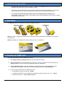
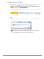
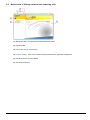
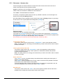
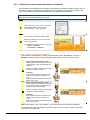
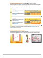
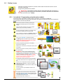
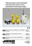
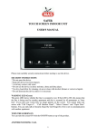
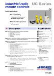
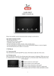
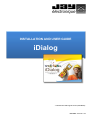
INSTALLATION AND USER GUIDE iDialog - Translated from FRA original version (351910B-FR) - DOC REF : 351910B - EN TABLE OF CONTENTS 1 GENERAL SAFETY RULES..................................................................................................................................................... 3 2 OVERVIEW......................................................................................................................................................................... 3 3 CONTENT OF USB CARD ..................................................................................................................................................... 3 4 INSTALLING THE IDIALOG SOFTWARE................................................................................................................................. 4 4.1 SOFTWARE COMPATIBILITY AND INSTALLATION REQUIREMENTS ........................................................................................................... 4 4.2 INSTALLATION PROCEDURE : ......................................................................................................................................................... 4 5 USING THE IDIALOG SOFTWARE ......................................................................................................................................... 5 5.1 HOME SCREEN : ......................................................................................................................................................................... 5 5.1.1 import a parameter settings file ................................................................................................................................. 6 5.2 MAIN SCREEN OF IDIALOG SOFTWARE AFTER IMPORTING A FILE ........................................................................................................... 7 5.3 « EDIT PARAMETERS » MENU ....................................................................................................................................................... 8 5.3.1 Sub-menu : User interface .......................................................................................................................................... 8 Startup screen............................................................................................................................................................ 8 Operator module language ....................................................................................................................................... 8 5.3.2 Sub-menu : General settings ...................................................................................................................................... 9 Infrared (IR) mode ..................................................................................................................................................... 9 Passive stop time ....................................................................................................................................................... 9 Standby function........................................................................................................................................................ 9 Operation (of operator module) on charger .............................................................................................................. 9 « Dead-man » function .............................................................................................................................................. 9 5.3.3 Sub-menu : Access rules ........................................................................................................................................... 10 Configuration PIN code ............................................................................................................................................ 10 Learning (association) PIN code .............................................................................................................................. 10 Start++ PIN code ...................................................................................................................................................... 10 Start PIN code .......................................................................................................................................................... 10 5.4 MENU « WORDING »............................................................................................................................................................... 11 5.4.1 Text editing ............................................................................................................................................................... 11 5.4.2 Calibrating a measurement (information feedback) ................................................................................................ 12 « Field » calibration method on installation ............................................................................................................ 12 « Theoretical » calibration method ......................................................................................................................... 13 « Thresholds reached» information message .......................................................................................................... 13 5.5 “SETTING” MENU..................................................................................................................................................................... 14 5.5.1 1st method : Programming using Operator module ................................................................................................ 14 5.5.2 2nd method : programming using the Transceiver .................................................................................................. 15 5.5.3 3rd method: Programming using the Transceiver and the Operator module .......................................................... 16 5.6 CLOSING THE PARAMETER DEFINITION FILE .................................................................................................................................... 17 2 / 17 351910B-EN 1 General safety rules • This manual is valid from the version number : 1.0.4.17 of the iDialog software (the version number is viewable in the lower right corner on the home screen). • To avoid any risk of electrocution, do not open the Transceiver unit when powered up. The unit must only be opened after you have made sure that the power and control cables are shut down. • We strongly recommend that you keep a copy of the initial parameter settings file (all configuration change will « overwrite » the previous version when pressing the "save" button or exiting the application (red cross)). 2 Overview The iDialog software is designed for use with the safir product line. iDialog is used to configure the radio remote control system and customise the information on the operator module screen. iDialog is supplied as a standard item with the safir products on a USB card : 3 Content of USB card The USB card supplied with each safir pack contains : 1. The iDialog software installation files (as well as the product drivers). 2. The « solution pack » parameter settings file (file with « .idialog » extension to be opened with the iDialog software in order to modify the equipment parameter definitions) 3. The configuration sheet in PDF format detailing the parameter settings of the hardware solution supplied and describing the method for wiring the installation (directory "FicheParametre”). 4. A set of technical manuals for the safir product line: 351910B-EN • An installation and user manual, ref. :351260, • A simplified installation and user guide (also supplied in hardcopy with the pack), ref. : 351270, • Product brochures, ref. : P-001, P-002, P-003 etc… 3 / 17 4 Installing the iDialog software 4.1 4.2 Software compatibility and Installation requirements • iDialog is only compatible with the following environments: - Windows XP (SP3) 32 bits, - Vista 32 bits, - 7 Seven (SP1).32 bits and 64 bits • iDialog requires an internet connection for the automatic installation of software components .NET FRAMEWORK 4. • The software installation requires all « Administator » rights. Installation procedure : 1 Pull out the USB connector on the card 2 Connect the card to a USB port on your computer The following home screen will appear. Launch the iDialog installation by clicking on the “Setup iDialog” button. 3 4 5 Note: Depending on the configuration of your computer, the installation home screen will not necessarily be automatically launched. If this is the case, open the file explorer and launch the « SETUP.EXE » file located at the root of the USB card. The installation begins. Once the installation is completed, an iDialog shortcut icon will be automatically placed on the operating system desktop. You can now launch the software. 4 / 17 351910B-EN 5 Using the iDialog software IMPORTANT : We strongly recommend that you keep a copy of the initial parameter settings file (all configuration change will « overwrite » the previous version when pressing the "save" button or exiting the software (red cross)). 5.1 Home screen : (1) Link to JAY Electronique website, « contact us » form (2) Link to JAY Electronique website, « home» (3) Link to JAY Electronique website, « On-line help» (4) « About » button : giving general information concerning the current version of the iDialog software (5) Choice of language for software interface (6) « Save » button (inactive until importing a parameter settings file). (7) « Import a file » button : see next chapter (8) Version number of iDialog software 351910B-EN 5 / 17 5.1.1 import a parameter settings file The complete set of settings and configurations of the radio remote control system supplied is contained in a file in the USB card in the « …\Parameter Sheet » directory. The name of the parameter settings file corresponds to a serial number of the product with extension « .iDialog », ex : « FPI123456789.iDialog » To view or modify product parameter settings, a parameter settings file must be imported from the iDialog software. Note : If the selected file is an old format or was edited with an older version of iDialog software, an error message appears: The configuration file must be updated. Please, Contact JAY Electronique Technical Support who will send you back a compatible file. 6 / 17 351910B-EN 5.2 Main screen of iDialog software after importing a file (1) Name and path of the parameter settings file being edited (2) Function tabs (3) List of sub-menus of current tab (4) « Save » button : save at any time the changes made on the parameter settings file (5) Functions which can be modified (6) Function parameters 351910B-EN 7 / 17 5.3 « Edit parameters » menu This menu is used to modify certain settings of the radio remote control system corresponding to the « configuration » menu of the Operator Module with additional functions. 5.3.1 Sub-menu : User interface Startup screen When the operator module is started up, a logo-image (or text image) may be displayed on the screen. You can customise this illustration by importing an image file. The accepted formats are .jpg, .png or .bmp . The picture dimensions must meet these four rules : 1. Maximum height = 128 pixels 2. Maximum width = 128 pixels 3. Maximum number of pixels = 9216 (number of pixels in a picture = Height px * Width px, i.e. : picture with 64 px height and 128 px width = 8192 pixels) 4. The height and the width dimensions must be multiples of 8 (i.e. : 32, 48, 80, 120, 128 px) Note: Since the display on the screen is black/white, it is best to import a black/white monochrome image file. The Paint software supplied with the Windows OS or the GIMP freeware are recommended for this operation. The Default screen button automatically imports the JAY Electronique logo as startup screen. Operator module language This is the language which will be used to display text on the operator module screen (configuration menu and system message). 8 / 17 351910B-EN 5.3.2 Sub-menu : General settings The parameters which can be modified in this menu concern functions and options described in the installation and user technical manual (ref. :351260). Note: Certain parameters are not available in the solution pack supplied. Infrared (IR) mode • Activation or deactivation of IR mode • Choice : − Startup by validation of an infrared signal or − Limitation of action area by infrared Passive stop time • The passive stop time can be configured as follows: − 300ms − 500ms − 1s − 1,5s − 2s Standby function • Activation or deactivation of function • Time delay before function is triggered, configurable between 60 and 3600s. Operation (of operator module) on charger • Stop or leave operator module in operation (radio transmission and active safety stopped) • Choice of operator mode to be activated when operator module is in operation on its charger. « Dead-man » function • Activation or deactivation of function • Pre-alarm and period configurable between 0 and 127s. 351910B-EN 9 / 17 5.3.3 Sub-menu : Access rules The access rights are used to authorise or restrict the radio remote control user to the use of certain menus (functions) of the operator module. 4 types of restrictions can be configured with 4-digit PIN codes. These codes can be identical or different for each restriction. The « 0000 » code deactivates the restriction. On delivery, the operator module does not have any utilisation restriction; the access rights can only be set up using the iDialog software. If the PIN codes are lost or forgotten, these can be found using the iDialog software, by importing the last version of the system parameter settings files (.iDialog file). Important remark: The access codes are organised hierarchically. To program an association PIN access code, you must first have programmed a configuration PIN access code. Similarly, to program a Start PIN access code, you must first have programmed a configuration, association and optionally a Start++ PIN code. If this hierarchy is not observed, the access codes will not have any effect. Configuration PIN code This code is used to unlock access to the « configuration » menu of the Operator module. Note : for safety reasons, we strongly recommend that you enter a PIN code in order to restrict access to this menu. Learning (association) PIN code This code is used to unlock the « association » menu of the Operator module, and thus authorise a qualified user having a code to perform an association between the Operator module and the Transceiver. Note : For safety reasons, we strongly recommend that you enter a PIN code in order to restrict access to this menu . Start++ PIN code The « start++ » menu is a special startup mode defined when ordering the solution pack, in addition to the classic startup. The « start++ » allows a qualified user having a code to access all of the possible commands and functions of the radio remote control system. The associated PIN code is used to unlock this type of use (without an appropriate code, the user will nonetheless have access to the classic « start » menu). Start PIN code This code is used to unlock the « start » menu of the operator module and thus authorise a qualified user to startup and use the radio remote control system. 10 / 17 351910B-EN 5.4 Menu « Wording » This menu is used to modify the texts displayed on the screen of the Operator module and to perform calibration operations on possible information feedback from the Transceiver. 5.4.1 Text editing The operator module screen comprises 12 display areas. The number of areas which can be modified depends on the original configuration of the pack supplied; it is not possible to add areas subsequently. 1 (noneditable area) 2 3 = Pictogram, « battery level » = Pictogram, « Status of actions on control components » = Radio channel currently being used = Quality of radio link between Operator module and Transceiver Name of remote-controlled equipment (Common for all modes, 18 characters max.) Name of operating mode - line No.1 (18 characters max.) 4 Name of operating mode - line No. 2 (10 characters max.) OR information feedback No.1 from Transceiver (10 characters max., measurement + 10 characters max. for measurement unit) 5 Information feedback No.1 from Transceiver (10 characters max., measurement + 10 characters max. for measurement unit) OR information feedback No.2 from Transceiver (10 characters max., measurement + 10 characters max. for measurement unit) 6 Information feedback No.2 from Transceiver (10 characters max., measurement + 10 characters max. for measurement unit) OR information feedback No.3 from Transceiver (10 characters max., measurement + 10 characters max. for measurement unit) 7 8 9 10 11 12 a b c d e 351910B-EN Information relative to status of radio remote control system: Name of function or selection No.5 (8 characters max.) Name of function or selection No.3 (8 characters max.) Name of function or selection No.1 (8 characters max.) Name of function or selection No.6 (8 characters max.) Name of function or selection No.4 (8 characters max.) Name of function or selection No.2 (8 characters max.) Operating mode scrolling button Text scroll button (display operates in accordance with conditions defined on parameter settings sheet). Composition of pack supplied : representation of Operator module and Transceiver with their serial numbers Selector position : 0 = rest, 1 = 1st step, 2 = 2nd step « B » button (BOLD) to display text in BOLD type for selector or function button selected 11 / 17 5.4.2 Calibrating a measurement (information feedback) If the solution pack supplied has an analogue measurement information feedback function (use of an analogue input), the calibration can be performed using iDialog. The following procedure will allow you to calibrate the information displayed on the Operator module screen. IMPORTANT : Following calibration, The Operator module and the Transceiver must be programmed with new parameters (see §5.5). 1 In the « Wording » menu, click on one of the « information feedback» areas on the measurement (ex : « 20 » opposite) A measurement calibration window opens. 2 Select the analogue input of the concerned Transceiver (E-ANA). The adjustment can be performed in two ways: « Field » calibration « Theoretical » calibration « Field » calibration method on installation The calibration is performed by reading 2 measurement points: A and B (min. and max.). Example : Measurement of a suspended load (radio remote control of a gantry crane). Entering point A information (min.) : Fasten a load corresponding to 10% of the maximum load which can be lifted by the equipment. A Switch on the radio remote control system and perform a lifting operation. In iDialog : Enter the measurement indicated on the screen of the Operator module (value read). Enter the actual measurement of the load lifted (target value). Entering point B information (max.) : Fasten a load corresponding to 90% of the maximum load which can be lifted by the equipment (insofar as possible). B Switch on the radio remote control system and perform a lifting operation. In iDialog : Enter the measurement indicated on the screen of the Operator module (value read). Enter the actual measurement of the load lifted (target value). Note: If the values « read » are negative, you must first perform a theoretical calibration. To complete the « field » calibration procedure, click on the « validate » button. Then follow instructions on chapter 5.5. 12 / 17 351910B-EN « Theoretical » calibration method This calibration is performed by filling in points A and B (min. and max.) using the manufacturer’s data for the sensor connected to the analogue input of the Transceiver (voltage or current output as a function of the measurement performed). Example for a voltage calibration (Volt) : In iDialog : A Enter the minimum signal level of the sensor (value read). Enter the measurement performed by the sensor for this minimum signal level (target value) In iDialog : B Enter the maximum signal level of the sensor (value read). Enter the measurement performed by the sensor for this maximum signal level (target value) To complete the « theoretical» calibration procedure, click on the « validate » button. Then follow instructions on chapter 5.5. « Thresholds reached» information message A message can be displayed on the operator module screen if one of the thresholds (min. and max.) entered in the « Calibration » window is reached. This information is given in place of the current measurement (information feedback position) : 351910B-EN 13 / 17 5.5 “Setting” menu This menu is used to program the operator module and the transceiver with the current parameter settings file. 3 programming methods are possible. IMPORTANT: The operator module must be associated with the Transceiver to perform programming (follow the "association" procedure described in the installation and user manual ref:. 351260) 5.5.1 1st method : Programming using Operator module For this procedure, the operator module must be connected to a computer by a USB cord. Once programmed with the new parameter settings file, the Operator module will transfer the configuration changes to the Transceiver by radio link. 1 2 3 Switch off the Operator module (by pressing the emergency stop palmswitch). Do not remove the battery. Open the USB connection cover on the operator module using a 5mm flat tip screwdriver. Connect the Operator module to the computer using the USB cord supplied with the solution pack. If the connection is successful, the iDialog software will display the Operator module recognised information. Click on the « SETTING » programming button. The iDialog software sends the data to the Operator module. Do not disconnect the Operator module during the programming phase. Once the programming procedure is completed, disconnect the USB cord. Switch on the Transceiver (the reception antenna must be in place). 4 Switch on the Operator module (unlock the emergency stop palmswitch). IMPORTANT : After you have pressed the green validation button, the Operator module will propose transmitting the new configuration to the Transceiver by radio link. Validate the choice by « Apply ». If this procedure is not executed (« Discard » choice), the Operator module operating configuration will be different from that of the Transceiver. The Operator module will search for the associated Transceiver and send the new configuration by radio link. 5 Once the new configuration has been transmitted, press the green « validation » button; the Operator module shuts down. Press the green button a second time to switch on the Operator module. You can now start up the installation with the new configuration. If a problem has occurred while the data was being transmitted (Operator module and/or Transceiver shut down), the « Bad parameters » message will appear on the Operator module screen. Resume the procedure at step No. 4. 14 / 17 351910B-EN 5.5.2 2nd method : programming using the Transceiver To perform this procedure, the Transceiver must be connected to a computer by a USB cord. Once the Transceiver is programmed with the new parameter settings file, a teaching procedure must be performed to transfer the new configuration to the Operator module by radio link. 1 Switch off the Operator module (by pressing the emergency stop palmswitch). Switch off the Transceiver. Open the Transceiver unit. 2 3 Connect the USB cord to the Transceiver and connect it to the computer. If the connection is successful, the iDialog software will display the Transceiver recognised information. Click the “SETTING” programming button. The iDialog software will send the data to the Transceiver. Do not disconnect the Transceiver during the programming phase. Once the programming is completed, disconnect the USB cord. Switch on the Transceiver (the reception antenna must be in place). 4 Switch on the operator module (by unlocking the emergency stop palmswitch). IMPORTANT : After you have pressed the green validation button, perform a « Association » procedure to modify the configuration of the Operator Module (see installation and user manual 351260). If this teaching procedure is not executed, the operating configuration of the Transceiver will be different from that of the Operator module. The Operator module will search for the Transceiver. Once the Transceiver has been found, validate the association. 5 The Transceiver will then transmit the new configuration to the operator module by radio link. Once the configuration has been transmitted, press the green « validation » button; the Operator module shuts down. Press the green button a second time to switch on the Operator module. You can now start up the installation with the new configuration. If a problem has occurred while the data was being transmitted (Operator module and/or Transceiver shut down), the « Bad parameters » message will appear on the Operator module screen. Resume the procedure at step No. 4. 351910B-EN 15 / 17 5.5.3 3rd method: Programming using the Transceiver and the Operator module To perform this procedure, the Transceiver and the Operator module must be connected to a computer by 2 USB cords. Once the products have been programmed with the new parameter settings file, the radio remote control system is directly operational. Switch off the Operator module (by pressing the emergency stop palmswitch). 1 Switch off the Transceiver. Open the USB connection cover on the Operator module. Open the Transceiver unit. 2 Connect a USB cord to the Transceiver and connect it to the computer. Repeat the operation for the Operator module. If the connections are successful, the iDialog software will display the product information. Click on the «SETTING» programming button. 3 The iDialog software will transmit the data to the Operator module and to the Transceiver. Do not disconnect the products during the programming phase. Once the programming is completed, disconnect the USB cords. 4 Switch on the Transceiver. Switch on the Operator module (by unlocking the emergency stop palmswitch). After you have pressed on the green validation button, you can startup the installation with the new configuration. 16 / 17 351910B-EN 5.6 Closing the parameter definition file This button is used to close the parameter definition file (saved with changes). After you have pressed this button, the software will return to the home screen. Note: Closing the application (red X at upper right corner) will have the same effect. 351910B-EN 17 / 17