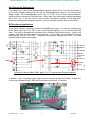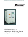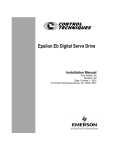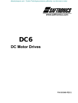
1
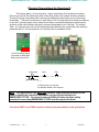
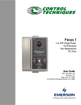
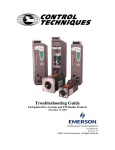
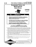
efesotomasyon.com - Control Techniques,emerson,saftronics -ac drive-servo motor
Application
Note
CTAN #163
The Application Note is pertinent to the Quantum III/Mentor II Family
Dual Stopping Rates
Quite often there is a need for 2 deceleration rates when using motor drives. Usually there is a
normal stop rate and the need for an occasional Fast or quick decel stopping rate. The ability
of a DC Drive to stop a motor quickly usually means that a Regenerative model drive is
required This application note will address how one might create dual stopping rates.
On a Stop command the drive will ramp to stop using the default decel rate which is contained
in parameter #2.05 ( decel rate #1 ). You can refer to the diagram of Menu 2 shown below.
There 2 decel rates available. We would use Decel #2 or #2.09 for our alternate rate, but
how can it be selected? Obviously, we will need an input to tell the drive when to use this
alternate rate. This can be accomplished if we can change the position of the deceleration
rate selector- #2.18.
Note: For Regenerative Drive Models and where both forward and reverse motor directions
are being utilized, there is a separate set of decel rates that would come into play in the
reverse direction- namely #2.06 and #2.10.
efesotomasyon.com - Control Techniques,emerson,saftronics -ac drive-servo motor
Uni-Directional Applications
If we assign one of the unused programmable inputs to control #2.18, we’ll just about have it.
If you have a Regen model but do not use the Forward/Reverse input or if you have a NonRegen model, the Forward/Reverse input ( pin 11 of TB1 on the 115vac Interface Board )
would be free for use as the Fast Stop input. In this case, you would merely change parameter
#8.14 from 112 to 218 and refer to the Physical Connections section of this App Note.
Whenever configuration changes are made, you must depress reset for them to take effect.
Bi-Directional Applications
If you have a Regen model and use the Forward/Reverse input, you could re-configure the
Drive Reset input ( pin 12 of TB1 on the 115vac Interface Board ) for use as the Fast Stop
input. This input is shipped from the factory as an External Fault Reset function. If this is not
needed, this input would be ideal for this purpose. In this case, you would merely change
parameter #8.15 from 115 to 218. Whenever configuration changes are made, you must
depress reset for them to take effect.
Quantum III Manual March 2002 page 37 or 212 Interconnect Diagram segment
In addition, when re-configuring the Reset input for something other than Reset, jumper JP1
of the Logic Interface Board ( 9500-4030) must be moved to the 1-2 position.
CTAN163.doc
V1.3
2
05/05/06
efesotomasyon.com - Control Techniques,emerson,saftronics -ac drive-servo motor
Physical Connections for Quantum III
The hookup below ( 3-wire scenario) uses a momentary Run contact to cause the
Drive to go into the Run Mode and either of the Stop buttons will unlatch the Run condition.
The key to having a dual Stop rate is having the additional contact block on the Quick Stop
pushbutton. The button shown here is the Push-In/ Pull Out type that will maintain the closure
on the NO ( normally open ) block when Quick Stop is commanded thereby maintaining the
selection of the second decel rate which we have designated as our Fast rate. For normal
Stop, our Fast rate input will not be selected thereby selecting the normal Stop rate setting in
parameter #2.05. We would place our Fast Stop rate in parameter #2.09.
115vac Run/Stop Wiring
connected to 9500-4025
Relay Logic Board TB1
Quick Stop
Stop
5
10
Run
6
7
11 or 12
11 if Reverse is not required
12 if Remote Reset is not required
Note: This application note does not intend to imply that this method can be
used to satisfy the Industrial Standards concerning the definition of
EMERGENCY STOP. One should consult OSHA or other machine safety
standards concerning EMERGENCY STOP and the required criteria.
Consult all NEC and OSHA machine safety recommendations and guidelines.
CTAN163.doc
V1.3
3
05/05/06
efesotomasyon.com - Control Techniques,emerson,saftronics -ac drive-servo motor
APPLICATION SAFETY
When applying a motor drive in a manufacturing process, one must understand that
the motor drive merely provides the energy for a motor to turn and it will do so without
regard upon activation and command. There could be failure modes in any external
interface equipment and/or the Drive itself that could cause the motor to turn suddenly
at any speed or cause it to fail to stop on command without warning. When
considering Operator safety the Installer must include and employ additional
equipment to provide safeguards to insure Operator safety. Typically this involves the
topic of EMERGENCY STOPPING.
Consult all NEC and OSHA machine safety recommendations and
guidelines.
Below are a few helpful links to associated topics:
Click ->
Click ->
Click ->
Click ->
Click ->
Click ->
ISO 13850:1996 is a document available from ANSI
OSHA Guidelines
Plant Safety Guidelines
Remote start/stop of drives
EN 954-1 excerpts
Control Engineering Article
Typically, Emergency Stop methods DO NOT utilize or depend on the motor drive to
stop the motor or machine in Emergency situations. They usually employ external
independent devices and/or methods to bring the motor or machine to rest in
expeditious and stable manner.
These safeguards are the sole responsibility of the Installer. For these reasons, the
Installer must envision all, implement all and test or simulate all failure methods. The
Installer is responsible for his/her resulting implementation to insure safe and reliable
operation of the installation.
In addition, the Installer should provide the End User of his Installed system with a
System User’s Manual and instruct the User/Operator on correct/safe operation.
Instruction should include the demonstration and purpose of safety features that you
the Installer have included and the importance of periodic testing to insure they do
indeed operate as originally designed. The Installer should instruct, inform and warn
his End User customer against bypassing the safety permissives the Installer has
provided.
CTAN163.doc
V1.3
4
05/05/06
efesotomasyon.com - Control Techniques,emerson,saftronics -ac drive-servo motor
System Interface Suggestions
A fundamental basic system interface suggestion would be to always employ a method to
supply a “permissive” or System Enable to allow the drive system to work if all things on the
machine are alright. This interface would provide a method to keep the System disabled if
certain key safety permissives are not satisfied. The installer should instruct, inform and
warn his End User customer against bypassing the safety permissives the Installer has
provided. The System Enable function would also have the ability to disable the drive if it was
in operation and some safety device were tripped or if the Operator encountered a need to
request an Emergency Stop for instance.
The external relay logic system outlined below would provide a basic yet effective method of
supplying an overall System Enable for a Drive installation.
115vac
Machine Ok to Run
Enable)
Emergency
Stop
Keyswitch or similar
to enable machine
Stays in when pressed
Pull to Reset
(
Enable Machine
SYSRDY
Motor Thermal Switch
Motor Blower Thermal
or Air flow verification
( see Optional Items )
All other safety interlocks such as but not limited to:
SYSRDY
System Ready
Light Curtains, Overspeed or Over-Travel Limit
Switches, Safety Gates/Ropes, Jam Detection, Kill
Switches, Overpressure Switches etc
A contact from the SYSRDY ( System Ready ) relay
above would become contact for the Drive Enable(s).
SYSRDY
For Quantum III Drives- pins 1-4 on AC Interface
For Mentor II Drives- pins 31-40 on TB4 (for neg logic)
Drive
For Quantum III Drives the items listed or shown in the ladder example rung above can be placed
between terminals 1-4 on the 9500-4025 AC Interface Board. See Quantum III Interconnect diagram for
details.
From above, the Machine OK to Run, can be a composite of a wide range of safety
interlocking devices. Typically these devices provide a closed contact if the safety condition
that they are monitoring is ok or within limits. These may include but are not limited to:
Light curtains- a light beam that when cut indicates a person has entered an area of safety
concern
Safety Ropes- a rope, that when tripped over, disturbed or moved, opens a switch
Safety Gate/Guard switch- a switch placed on a safety gate or guard that indicates a person
has removed a guard, cover or opened a gate and has entered an area of safety concern
CTAN163.doc
V1.3
5
05/05/06
efesotomasyon.com - Control Techniques,emerson,saftronics -ac drive-servo motor
Over Travel Limit Switches- a switch placed at the ends of a machine that indicate the
machine has traveled erroneously beyond normal limits and must be shutdown or stopped
quickly.
Kill Switches- a switch provided for the Operators, Maintenance or any other person who is
near a machine to shut it down. Typically these are placed throughout the machine for ease of
access. Some may be automatic in nature. For example,
-if one removes their hands from the controls a kill switch may be activated
-if one falls down or moves away from an Operator position a kill switch may be activated
Over Speed Limit Switches- a switch that indicates the machine has exceeded a safe design
speed limit erroneously and deemed “out of control” and must be shutdown. Sometimes
these are in the form of centrifical switches mounted on the end shaft of a motor or piece of
machine.
E-Stop Pushbuttons -- ( Emergency Stop ) typically a large Red mushroom head button that
opens a Normally closed contact which would cause a system to shutdown. They are
commonly placed throughout the machine for ease of access. Typically, this E-Stop function,
activates some for of rapid shutdown mechanisms that will cause the machine to halt in a short
period of time. These shutdown mechanisms may include Friction Brakes, DB resistors on DC
Drives or other combinations that would bring the mechanical system to a s Stop and place it
in a more stable safe condition.
A safer E-Stop pushbutton type are those that when pushed in –stay in- and require to be
pulled out to reset them.
Field Loss Detection- On Systems with DC motors, the Loss of Field excitation can cause a
motor to rapid accelerate to unsafe speeds. For this reason, a method of Field Loss detection
should be incorporated in any good System design.
*** Optional Items
Although Motor Thermal switches, Blower motor starter overloads, air flow vane switches and
similar items are sometimes inserted in this System Ready string, these items could be
considered non-emergency situations and could be inserted in the normal Drive Stop string
versus the System Ready string. In the case of Motor Thermal switches etc, one should
insure that Field Excitation is setup to reduce to a low value should a thermal switch be used to
Stop or trip the drive. One must test and verify that this does indeed function properly.
Questions ?? Ask the Author:
Author:
Ray McGranor
(716)-774-0093
CTAN163.doc
V1.3
e-mail : [email protected]
6
05/05/06