1
User Guide
Quantum MP
High Performance DC Drive
Size 1 and Size 2
45A to 700A, 480V
two or four quadrant operation
Part Number: 400526-01
Issue: A3
www.emersonct.com
General Information
The manufacturer accepts no liability for any consequences resulting from inappropriate, negligent or incorrect
installation or adjustment of the optional operating parameters of the equipment or from mismatching the variable speed
drive with the motor.
The contents of this guide are believed to be correct at the time of printing. In the interests of a commitment to a policy
of continuous development and improvement, the manufacturer reserves the right to change the specification of the
product or its performance, or the contents of the guide, without notice.
All rights reserved. No parts of this guide may be reproduced or transmitted in any form or by any means, electrical or
mechanical including photocopying, recording or by an information storage or retrieval system, without permission in
writing from the publisher.
Drive software version
This product is supplied with the latest version of software. If this product is to be used in a new or existing system with
other drives, there may be some differences between their software and the software in this product. These differences
may cause this product to function differently. This may also apply to drives returned from a Control Techniques Service
Centre.
The software version of the drive can be checked by looking at Pr 11.29 (di14/0.49) and Pr 11.34. The software version
takes the form of zz.yy.xx, where Pr 11.29 (di14/0.49) displays zz.yy and Pr 11.34 displays xx, i.e. for software version
01.01.00, Pr 11.29 (di14/0.49) would display 1.01 and Pr 11.34 would display 0.
If there is any doubt, contact a Control Techniques Drive Centre.
Environmental statement
Control Techniques is committed to minimising the environmental impacts of its manufacturing operations and of its
products throughout their life cycle. To this end, we operate an Environmental Management System (EMS) which is
certified to the International Standard ISO 14001. Further information on the EMS, our Environmental Policy and other
relevant information is available on request, or can be found at www.greendrives.com.
The electronic variable-speed drives manufactured by Control Techniques have the potential to save energy and
(through increased machine/process efficiency) reduce raw material consumption and scrap throughout their long
working lifetime. In typical applications, these positive environmental effects far outweigh the negative impacts of product
manufacture and end-of-life disposal.
Nevertheless, when the products eventually reach the end of their useful life, they can very easily be dismantled into their
major component parts for efficient recycling. Many parts snap together and can be separated without the use of tools,
while other parts are secured with conventional screws. Virtually all parts of the product are suitable for recycling.
Product packaging is of good quality and can be re-used. Large products are packed in wooden crates, while smaller
products come in strong cardboard cartons which themselves have a high recycled fibre content. If not re-used, these
containers can be recycled. Polythene, used on the protective film and bags for wrapping product, can be recycled in the
same way. Control Techniques' packaging strategy favours easily-recyclable materials of low environmental impact, and
regular reviews identify opportunities for improvement.
When preparing to recycle or dispose of any product or packaging, please observe local legislation and best practice.
REACH legislation
EC Regulation 1907/2006 on the Registration, Evaluation, Authorisation and restriction of Chemicals (REACH) requires
the supplier of an article to inform the recipient if it contains more than a specified proportion of any substance which is
considered by the European Chemicals Agency (ECHA) to be a Substance of Very High Concern (SVHC) and is
therefore listed by them as a candidate for compulsory authorisation.
For current information on how this requirement applies in relation to specific Control Techniques products, please
approach your usual contact in the first instance. Control Techniques position statement can be viewed at:
http://www.controltechniques.com/CTcom/system_pages/environment/reach_regulation.aspx
Copyright
© January 2011 Control Techniques Americas LLC
Issue Number: A3
Software:
01.05.01 onwards
1
Safety Information .................................5
5
1.1
1.2
1.3
1.4
1.5
1.6
1.7
1.8
1.9
1.10
Warnings, Cautions and Notes .............................5
Electrical safety - general warning ........................5
System design and safety of personnel ................5
Environmental limits ..............................................5
Access ..................................................................5
Fire protection .......................................................5
Compliance with regulations .................................5
Motor .....................................................................5
Adjusting parameters ............................................5
Electrical installation .............................................5
5.1
5.2
5.3
5.4
5.5
5.6
5.7
5.8
5.9
5.10
2
Product Information ..............................6
2.1
2.2
2.3
2.4
2.5
2.6
2.7
Quantum MP System Description .........................6
Ratings ..................................................................6
Model number .......................................................7
Compatible encoders ............................................8
Nameplate description ..........................................8
Drive features and options ....................................9
Items supplied with the drive ...............................13
3
Mechanical Installation .......................14
3.1
3.2
3.3
3.4
3.5
3.6
3.7
3.8
3.9
3.10
Safety ..................................................................14
Planning the installation ......................................14
Terminal cover removal ......................................15
Mounting method ................................................18
Enclosure ............................................................20
Heatsink fan operation ........................................22
IP Rating (Ingress Protection) .............................22
Electrical terminals - Size 1 .................................23
Electrical terminals - Size 2 .................................24
Routine maintenance ..........................................25
4
Electrical Installation ..........................26
4.1
4.2
4.3
4.4
4.5
4.6
4.7
4.8
4.9
4.10
4.11
4.12
4.13
4.14
4.15
4.16
4.17
Electrical connections/ Power connections .........28
Ground connections ............................................36
AC supply requirements ......................................36
Line reactors .......................................................37
Auxiliary AC supply and connections ..................37
Separating the Auxiliary Supply ..........................38
Control 120 Vac supply .......................................38
Control 24 Vdc supply .........................................38
Cable and fuse size ratings .................................39
External suppressor resistor ...............................42
Ground leakage ..................................................43
EMC (Electromagnetic compatibility) ..................43
Serial communications connections ....................45
Shield connections ..............................................46
Control connections ............................................46
General ...............................................................50
Connecting an encoder .......................................54
Quantum MP User Guide
Issue Number: A3
Getting Started ....................................55
Understanding the display ..................................55
Keypad operation ................................................55
Menu 0 (sub block) .............................................57
Pre-defined sub blocks .......................................58
Menu 0 (linear) ....................................................59
Menu structure ....................................................59
Advanced menus ................................................60
Saving parameters ..............................................60
Restoring parameter defaults ..............................61
Displaying parameters with non-default values only
61
5.11 Displaying destination parameters only ..............61
5.12 Parameter access level and security ..................61
5.13 Serial communications ........................................63
6
Basic parameters ................................64
6.1
Full descriptions ..................................................65
7
Running the Motor ...............................72
7.1
7.3
7.4
Quick start commissioning / start-up (from USA
defaults) ..............................................................73
Quick start commissioning / start-up (from
European defaults) ..............................................75
CTSoft software commissioning tool ...................77
Setting up a feedback device ..............................77
8
Optimization .........................................78
8.1
8.2
8.3
8.4
8.5
8.6
Armature current .................................................78
Speed feedback ..................................................78
Field current ........................................................78
Current loop gains self-tuning .............................78
Speed loop gains tuning .....................................79
Current limit tapers ..............................................80
9
SMARTCARD Operation .....................81
9.1
9.2
9.3
9.4
9.5
9.6
Introduction .........................................................81
Easy saving and reading .....................................81
Transferring data .................................................81
Data block header information ............................83
SMARTCARD parameters ..................................83
SMARTCARD trips .............................................85
10
Onboard PLC .......................................87
10.1
10.2
10.3
10.4
10.5
10.6
10.7
Onboard PLC and SYPT Lite ..............................87
Benefits ...............................................................87
Limitations ...........................................................87
Getting started ....................................................88
Onboard PLC parameters ...................................88
Onboard PLC trips ..............................................89
Onboard PLC and the SMARTCARD .................89
7.2
3
www.emersonct.com
11
Advanced Parameters .........................90
11.1
11.2
11.3
11.4
11.5
11.6
11.7
11.8
11.9
11.17
11.18
11.19
11.20
11.21
11.22
11.23
Menu 1: Speed reference ....................................96
Menu 2: Ramps .................................................100
Menu 3: Speed feedback and speed control .....103
Menu 4: Torque and current control ..................106
Menu 5: Motor and field control .........................108
Menu 6: Sequencer and clock ...........................112
Menu 7: Analog I/O ...........................................114
Menu 8: Digital I/O ............................................116
Menu 9: Programmable logic, motorized pot and
binary sum .........................................................120
Menu 10: Status and trips .................................123
Menu 11: General drive set-up ..........................124
Menu 12: Threshold detectors, variable selectors
and brake control function .................................125
Menu 13: Position control ..................................130
Menu 14: User PID controller ............................134
Menus 15, 16 and 17: Solutions Module slots ..137
SM-I/O120V Solutions Module parameter settings .
137
Menu 18: Application menu 1 ............................140
Menu 19: Application menu 2 ............................140
Menu 20: Application menu 3 ............................140
Menu 21: Second motor parameters .................141
Menu 22: Additional Menu 0 set-up ..................141
Menu 23: Header selections .............................141
Advanced features ............................................142
12
Technical Data ...................................147
11.10
11.11
11.12
11.13
11.14
11.15
11.16
12.1 Drive technical data ...........................................147
12.2 Cable and fuse size ratings ...............................149
12.3 Optional external EMC filters ............................154
13
Diagnostics ........................................157
13.1
13.2
13.3
13.4
13.5
13.6
13.7
Trip indications ..................................................157
Trip indications ..................................................157
Trip Categories ..................................................164
Alarm indications ...............................................165
Status indications ..............................................165
Displaying the trip history ..................................165
Behavior of the drive when tripped ....................165
14
UL Information ...................................166
14.1
14.2
14.3
14.4
14.5
Common UL Information ...................................166
AC supply specification .....................................166
Maximum continuous output current .................166
Safety label .......................................................166
UL Listed accessories .......................................166
List of tables ..................................... 167
Index .................................................. 169
4
www.emersonct.com
Quantum MP User Guide
Issue Number: A3
Safety
Product Mechanical Electrical
Information Information Installation Installation
Getting
Started
Basic
Running the
SMARTCARD
Optimization
parameters
Motor
Operation
1
Safety Information
1.1
Warnings, Cautions and Notes
1.4
Environmental limits
1.5
Access
Access must be restricted to authorized personnel only. Safety
regulations which apply at the place of use must be complied with.
WARNING
A Caution contains information which is necessary for
avoiding a risk of damage to the product or other equipment.
CAUTION
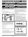
1.6
Electrical safety - general warning
The voltages used in the drive can cause severe electrical shock and/or
burns, and could be lethal. Extreme care is necessary at all times when
working with or adjacent to the drive.
Specific warnings are given at the relevant places in this Guide.
System design and safety of
personnel
Fire protection
The drive enclosure is not classified as a fire enclosure. A separate fire
enclosure must be provided.
1.7
NOTE
A Note contains information which helps to ensure correct operation of
the product.
1.3
Advanced Technical
UL
Diagnostics
Parameters
Data
Information
Instructions within the supplied data and information within the Quantum
MP User Guide regarding transport, storage, installation and the use of
the drive must be complied with, including the specified environmental
limits. Drives must not be subjected to excessive physical force.
A Warning contains information which is essential for
avoiding a safety hazard.
1.2
Onboard
PLC
Compliance with regulations
The installer is responsible for complying with all relevant regulations,
such as national wiring regulations, accident prevention regulations and
electromagnetic compatibility (EMC) regulations. Particular attention
must be given to the cross-sectional areas of conductors, the selection
of fuses and other protection, and protective ground (earth) connections.
The Quantum MP User Guide contains instructions for achieving
compliance with specific EMC standards.
Within the European Union, all machinery in which this product is used
must comply with the following directives:
2006/42/EC: Safety of machinery
2004/108/EC: Electromagnetic compatibility
The drive is intended as a component for professional incorporation into
complete equipment or system. If installed incorrectly, the drive may
present a safety hazard.
The drive uses high voltages and currents, carries a high level of stored
electrical energy, and is used to control equipment which can cause
injury.
System design, installation, commissioning and maintenance must be
carried out by personnel who have the necessary training and
experience. They must read this safety information and this guide
carefully.
The STOP and START controls or electrical inputs of the drive must
not be relied upon to ensure safety of personnel. They do not
isolate dangerous voltages from the output of the drive or from any
external option unit. The supply must be disconnected by an
approved electrical isolation device before gaining access to the
electrical connections.
The drive is not intended to be used for safety-related functions.
Careful consideration must be given to the function of the drive which
might result in a hazard, either through its intended behaviour or through
incorrect operation due to a fault. In any application where a malfunction
of the drive or its control system could lead to or allow damage, loss or
injury, a risk analysis must be carried out, and where necessary, further
measures taken to reduce the risk - for example, an over-speed
protection device in case of failure of the speed control, or a fail-safe
mechanical brake in case of loss of motor braking.
1.8
Motor
Ensure the motor is installed in accordance with the manufacturer's
recommendations. Ensure the motor shaft is not exposed.
Low speeds may cause the motor to overheat because the cooling fan
becomes less effective. The motor should be installed with a protection
thermistor. If necessary, an electric force vent fan should be used.
The values of the motor parameters set in the drive affect the protection
of the motor. The default values in the drive should not be relied upon.
It is essential that the correct value is entered into Pr 5.07 (SE07, 0.28),
Motor rated current. This affects the thermal protection of the motor.
1.9
Adjusting parameters
Some parameters have a profound effect on the operation of the drive.
They must not be altered without careful consideration of the impact on
the controlled system. Measures must be taken to prevent unwanted
changes due to error or tampering.
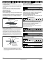
1.10
Electrical installation
1.10.1
Electric shock risk
The voltages present in the following locations can cause severe electric
shock and may be lethal:
•
•
•
AC supply cables and connections
Output cables and connections
Many internal parts of the drive, and external option units
Unless otherwise indicated, control terminals are single insulated and
must not be touched.
1.10.2
Stored charge
The drive contains capacitors that remain charged to a potentially lethal
voltage after the AC supply has been disconnected. If the drive has been
energized, the AC supply must be isolated at least ten minutes before
work may continue.
Quantum MP User Guide
Issue: A3
5
www.emersonct.com
Safety
Product Mechanical Electrical
Information Information Installation Installation
Getting
Started
Basic
Running the
SMARTCARD
Optimization
parameters
Motor
Operation
2
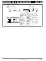
Product Information
2.1
Quantum MP System Description
Onboard
PLC
Advanced Technical
UL
Diagnostics
Parameters
Data
Information
The Quantum MP drive system consists of:
1)
Base Mentor MP DC drive
2)
Line fuses
3)
Armature fuse (Regenerative models only)
4)
Motor and Braking Resistor contactors
5)
120 Vac digital I/O and power source
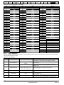
Table 2-1
Model to frame size cross reference
Model
Frame size
QMP45A4(R)
1A
QMP75A4(R)
QMP155A4(R)
1B
QMP210A4(R)
QMP350A4(R)
QMP400A4(R)
2A
QMP550A4(R)
2B
QMP700A4(R)
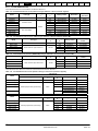
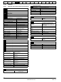
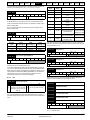
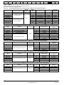
2.2
Ratings
The power ratings for the 480V configurations is shown in Table 2-2 .
The continuous current ratings given are for a maximum ambient
temperature of 40°C (104°F) and an altitude of 1000m. For operation at
higher temperatures and altitudes de-rating is required.
For further information see Chapter 12 Technical Data on page 147.
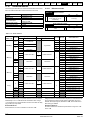
Table 2-2
480V drive ratings
AC input
current
Model
DC output current
Continuous Continuous Overload
Typical motor
power
@ 400
Vdc
@ 500
Vdc
hp
A
A
A
kW
QMP45A4(R)
38
45
67.5
15
27
QMP75A4(R)
63
75
112.5
27
45
QMP155A4(R)
130
155
232.5
56
90
QMP210A4(R)
175
210
315
75
125
QMP350A4(R)
313
350
525
125
200
QMP400A4(R)
360
400
600
150
250
QMP550A4(R)
492
550
825
200
300
QMP700A4(R)
626
700
1050
250
400
Maximum continuous input current
The values of maximum continuous input current are given to aid the
selection of cables and fuses. These values are stated for worst-case
condition.
6
www.emersonct.com
Quantum MP User Guide
Issue: A3
Safety
Product Mechanical Electrical
Information Information Installation Installation
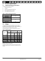
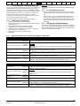
2.2.1
Getting
Started
Basic
Running the
SMARTCARD
Optimization
parameters
Motor
Operation
Onboard
PLC
Advanced Technical
UL
Diagnostics
Parameters
Data
Information
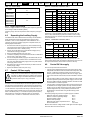
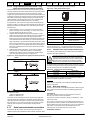
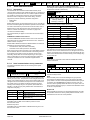
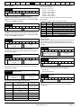
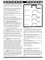
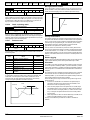
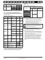
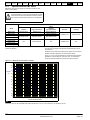
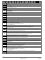
Typical short-term overload limits
The maximum percentage overload limit changes depending on the
selected motor
Variations in motor rated current will result in changes in the maximum
possible overload as detailed in the Advanced User Guide.
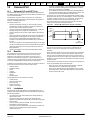
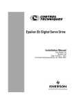
Figure 2-1 can be used to determine the maximum overload duration
available for overloads between 100% and 150%. For example the
maximum overload available for a period of 60 seconds is 124%.
Figure 2-1 Maximum overload duration available
160
155
150
145
overload
(%) 140
135
130
125
120
115
110
105
200
180
170
160
150
140
130
120
110
100
90
80
70
60
50
40
30
20
10
0
100
overload duration (seconds)
NOTE
Overload of 150% for 30s is available with ambient temperature of 40°C
(104°F) up to a maximum of 10 repetitions per hour.
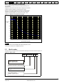
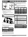
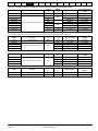
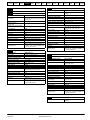
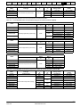
2.3
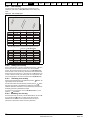
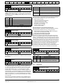
Model number
The way in which the model numbers for the Quantum MP range are formed is described in Figure 2-2.
Figure 2-2 Model number
QMP 2 1 0 A
4
R
Quantum product line
QMP: Quantum Platform
Continuous armature current rating (A)
Voltage rating
4: 480V
R - 4 quadrant operation
Blank - 2 quadrant operation
Quantum MP User Guide
Issue: A3
7
www.emersonct.com
Safety
Product Mechanical Electrical
Information Information Installation Installation
2.4
Table 2-3
Getting
Started
Basic
Running the
SMARTCARD
Optimization
parameters
Motor
Operation
Advanced Technical
UL
Diagnostics
Parameters
Data
Information
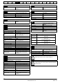
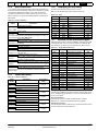
Compatible encoders
Encoders compatible with Quantum MP
Pr 3.38
(Fb07, 0.77)
setting
Encoder type
Quadrature incremental encoders with or without
marker pulse
Frequency and direction incremental encoders with
or without marker pulse
Forward / reverse incremental encoders with or
without marker pulse
2.5
Onboard
PLC
Ab (0)
Fd (1)
Fr (2)
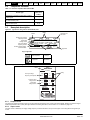
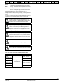
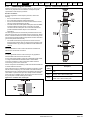
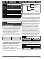
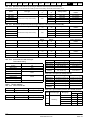
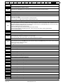
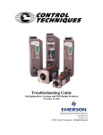
Nameplate description
Figure 2-3 Typical drive rating label for Quantum MP, size 1
Rating
Customer and
date code
Model
Auxiliary input voltage/
frequency/current
Field output
voltage current
Line input voltage/
frequency/current
Armature output voltage/
current/overload
QMP45A4
10 Min
15kW
27HP
STDN39
Aux I/P 208 - 480V -- 50-60 Hz 1 ph
Field O/P 0 - 444V --Line I/P 208 - 480V --- 50-60 Hz 3 ph
Arm O/P 0 - 550V --- 45 A
150% for
Ser No: 3000005001
8A
8A
38A
30s
LISTED 768R
IND. CONT. EQ.
E58592
RoHS
Compliant
Made in USA with US and Imported parts
Serial number
Approvals
Key to approvals
RoHS compliant
Europe
UL approval
Worldwide
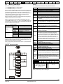
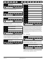
Figure 2-4 Typical drive rating label for Quantum MP. size 2
MODEL
Model
QMP350A4
AC INPUT
Line input voltage/
frequency/current/phase
VAC 240/460
HZ
50/60
Rating
A
313
PH
3
MAX DC OUTPUT
Armature output
voltage/current
Field output
voltage/current
VDC 240/500
A
350
VFL
A
20
150/300
PART NO.
QPM350A4R
SCHEMATIC
QMPS2-SCH-01
REV.
-REV.
01
AMERICAS
EDEN PRAIRIE, MN 55344
2.5.1
Output current
The continuous output current ratings given on the rating label are for maximum 40°C (104°F) and 1000m altitude. Derating is required for higher
ambient temperatures >40°C (104°F) and higher altitude. For derating information, refer to section 12.1.10 Altitude on page 148.
2.5.2
Input current
The input current is affected by the supply voltage, frequency and load inductance. The input current given on the rating label is the typical input
current.
8
www.emersonct.com
Quantum MP User Guide
Issue: A3
Safety
Product Mechanical Electrical
Information Information Installation Installation
2.6
Getting
Started
Basic
Running the
SMARTCARD
Optimization
parameters
Motor
Operation
Onboard
PLC
Advanced Technical
UL
Diagnostics
Parameters
Data
Information
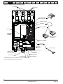
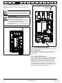
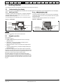
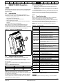
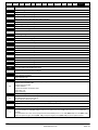
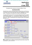
Drive features and options
Figure 2-5 Quantum MP size 1 features and options
AC terminals
SM-Keypad-LCD /
SM-Keypad-LED
SMARTCARD*
Solutions Modules
Feedback, Automation,
or Fieldbus
SM-I/O 120V module
Serial port connector
Control terminals
CT Comms cable
Auxiliary fuses
MP 10, 120 Vac
I/O user interface
Field connections
Auxiliary connections
* A SMARTCARD is provided as standard. For further information, refer
to Chapter 9 SMARTCARD Operation on page 81.
Quantum MP User Guide
Issue: A3
9
www.emersonct.com
Safety
Product Mechanical Electrical
Information Information Installation Installation
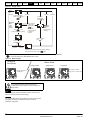
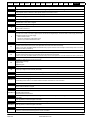
Figure 2-6
Getting
Started
Basic
Running the
SMARTCARD
Optimization
parameters
Motor
Operation
Onboard
PLC
Advanced Technical
UL
Diagnostics
Parameters
Data
Information
Quantum MP size 2 features and options
AC Terminals
Line Fuses
L2
L1
L3
GND
DANGER
HIGH VOLTAGE
SM-Keypad-LCD /
SM-Keypad-LED
Keypad connection
SmartCard *
Solutions Modules
Field Fuses
Machine
Feedback
Terminals
Feedback, Automation
or Fieldbus
SM-I/O 120V Module
Serial Port
connector
Control
Terminals
CT Comms cable
DANGER
HIGH VOLTAGE
A+
A-
GND
Transformer
Armature Fuse
(R) Models only
120 Vac I/O
user interface
Field Connections
DC Terminals
DC Contactor
Auxillary Connections
* A SMARTCARD is provided as standard. For further information, refer
to Chapter 9 SMARTCARD Operation on page 81.
10
www.emersonct.com
Quantum MP User Guide
Issue: A3
Safety
Product Mechanical Electrical
Information Information Installation Installation
2.6.1
Getting
Started
Basic
Running the
SMARTCARD
Optimization
parameters
Motor
Operation
Onboard
PLC
Advanced Technical
UL
Diagnostics
Parameters
Data
Information
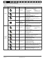
Options available for Quantum MP
All Solutions Modules are color-coded in order to make identification easy. The following table shows the color-code key and gives further details on
their function.
Table 2-4
Solutions Module identification
Type
Solutions Module
Color
Light Green
Name
SM-Universal
Encoder Plus
Feedback
Brown
Dark Brown
Quantum MP User Guide
Issue: A3
SM-Encoder Output
Plus
N/A
15-way D-type
converter
N/A
Single ended
encoder interface
(15V or 24V)
Yellow
Automation
(I/O
Expansion)
SM-Encoder Plus
SM-I/O Plus
Yellow
SM-I/O 32
Dark Yellow
SM-I/O Lite
Further Details
Universal Feedback interface
Feedback interface for the following devices:
Inputs
Outputs
• Incremental encoders
• Quadrature
• SinCos encoders
• Frequency and direction
• SSI encoders
• SSI simulated outputs
• EnDat encoders
Incremental encoder interface
Feedback interface for incremental encoders without
commutation signals.
No simulated encoder outputs available
Incremental encoder interface
Feedback interface for incremental encoders without
commutation signals.
Simulated encoder output for quadrature, frequency and
direction signals
Drive encoder input converter
Provides screw terminal interface for encoder wiring and spade
terminal for shield
Single ended encoder interface
Provides an interface for single ended ABZ encoder signals,
such as those from hall effect sensors. 15V and 24V versions
are available.
Extended I/O interface
Increases the I/O capability by adding the following to the
existing I/O in the drive:
• Digital inputs x 3
• Analog output (voltage) x 1
• Digital I/O x 3
• Relay x 2
• Analog inputs (voltage) x 2
Extended I/O interface
Increase the I/O capability by adding the following to the
existing I/O in the drive:
• High speed digital I/O x 32
• +24V output
Additional I/O
1 x Analog input (± 10V bi-polar or current modes)
1 x Analog output (0-10V or current modes)
3 x Digital input and 1 x Relay
SM-I/O Timer
Additional I/O with real time clock
As per SM-I/O Lite but with the addition of a Real Time Clock
for scheduling drive running
Turquoise
SM-I/O PELV
Isolated I/O to NAMUR NE37 specifications
For chemical industry applications
1 x Analog input (current modes)
2 x Analog outputs (current modes)
4 x Digital input / outputs, 1 x Digital input, 2 x Relay outputs
Olive
SM-I/O 120V
Additional I/O conforming to IEC 61131-2 120 Vac
6 digital inputs and 2 relay outputs rated for 120 Vac operation
Cobalt Blue
SM-I/O 24V
Protected
Additional I/O with overvoltage protection up to 48V
2 x Analog outputs (current modes)
4 x Digital input / outputs, 3 x Digital inputs, 2 x Relay outputs
Dark Red
11
www.emersonct.com
Safety
Product Mechanical Electrical
Information Information Installation Installation
Getting
Started
Basic
Running the
SMARTCARD
Optimization
parameters
Motor
Operation
Onboard
PLC
Advanced Technical
UL
Diagnostics
Parameters
Data
Information
Table 2-4 Solutions Module identification
Type
Solutions Module
Color
Name
Further Details
Applications Processor (with CTNet)
Moss Green
Automation
(Applications)
White
SM-Applications
Plus
2nd processor for running pre-defined and /or customer created
application software with CTNet support. Enhanced
performance over SM-Applications
Applications Processor
SM-Applications Lite 2nd processor for running pre-defined and /or customer created
V2
application software. Enhanced performance over SMApplications Lite
Applications Processor
Green brown SM-Register
Purple
SM-PROFIBUS DPV1
Medium Grey SM-DeviceNet
2nd processor for running position capture functionality with
CTNet support.
Profibus option
PROFIBUS DP adapter for communications with the drive
DeviceNet option
Devicenet adapter for communications with the drive
Dark Grey
SM-INTERBUS
Interbus option
Interbus adapter for communications with the drive
Light Grey
SM-CANopen
CANopen option
CANopen adapter for communications with the drive
Beige
SM-Ethernet
Ethernet option
10 base-T / 100 base-T; Supports web pages, SMTP mail and
multiple protocols: DHCP IP addressing; Standard RJ45
connection
Brown Red
SM-EtherCAT
EtherCAT option
EtherCAT adapter for communications with the drive
Fieldbus
Table 2-5
Keypad identification
Keypad
Table 2-6
Name
SM-Keypad
LED keypad option
Keypad with a LED display
SM-Keypad-Plus
LCD keypad option
Keypad with an alpha-numeric LCD display with Help function
Additional options
Cable
Name
CT Comms cable
Table 2-7
Further Details
Further Details
CT EIA232 (4500-0087)
CT USB (4500-0096)
External field control
External field controller
Name
Further Details
FXMP25
M
Mode /Reset
STORED CHARGE
10 min
FXMP25
For external control of field windings up to 25A, with field reversal capability, For
further information, please see the FXMP25 User Guide.
12
www.emersonct.com
Quantum MP User Guide
Issue: A3
Safety
Product Mechanical Electrical
Information Information Installation Installation
2.7
Getting
Started
Basic
Running the
SMARTCARD
Optimization
parameters
Motor
Operation
Onboard
PLC
Advanced Technical
UL
Diagnostics
Parameters
Data
Information
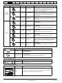
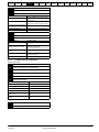
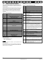
Items supplied with the drive
The drive is supplied with a printed manual, a SMARTCARD, a safety
information booklet, the Certificate of Quality, an accessory kit box
including the items shown in Table 2-8, and a CD ROM containing all
related product documentation and software tools.
Table 2-8
Parts supplied with the drive
Description
Size 1
Size 2
Control connectors
Tach connector
Relay connectors
UL warning label
CAUTION
CAUTION
Risk of Electric Shock
Power down unit 10minutes
before removing cover
Risk of Electric Shock
Power down unit 10minutes
before removing cover
UL warning label for heatsink
temperature
Terminal cover grommets
N/A
Terminal shrouds
Integral clear cover
Bottom mounting foot bracket (2)
Integral mounting base plate
Top mounting foot bracket (1)
Quantum MP User Guide
Issue: A3
13
www.emersonct.com
Safety
Product Mechanical Electrical
Information Information Installation Installation
Getting
Started
Basic
Running the
SMARTCARD
Optimization
parameters
Motor
Operation
Onboard
PLC
Advanced Technical
UL
Diagnostics
Parameters
Data
Information
3
Mechanical Installation
For further information, refer to section 3.5.2 Enclosure sizing on
page 21.
3.1
Safety
3.2.4
Follow the instructions
WARNING
The mechanical and electrical installation instructions must
be adhered to. Any questions or doubt should be referred to
the supplier of the equipment. It is the responsibility of the
owner or user to ensure that the installation of the drive and
any external option unit, and the way in which they are
operated and maintained, comply with the requirements of
applicable legislation and regulations and codes of practice
in the country in which the equipment is used.
Competence of the installer
WARNING
WARNING
The drive must be installed by professional assemblers who
are familiar with the requirements for safety and EMC. The
assembler is responsible for ensuring that the end product or
system complies with all the relevant laws in the country
where it is to be used.
Electrical safety
The installation must be safe under normal and fault conditions.
Electrical installation instructions are given in Chapter 4 Electrical
Installation on page 26.
3.2.5
Electromagnetic compatibility
If it is necessary to meet strict emission limits, or if it is known that
electromagnetically sensitive equipment is located nearby, then full
precautions must be observed. The use of an external EMC filter may be
required at the drive inputs, which must be located very close to the
drives.
Space must be made available for the filters and allowance made for
carefully segregated wiring. Both levels of precautions are covered in
section 12.2.3 Electromagnetic compatibility (EMC) on page 153
3.2.6
Hazardous areas
The drive must not be located in a classified hazardous area unless it is
installed in an approved enclosure and the installation is certified.
If the drive has been used at high load levels for a period of
time, the heatsink can reach temperatures in excess of 70°C
(158°F). Human contact with the heatsink should be
prevented.
Enclosure
WARNING
The drive is intended to be mounted in an enclosure which
prevents access except by trained and authorized
personnel, and which prevents the ingress of contamination.
It is designed for use in an environment classified as
pollution degree 2 in accordance with IEC 60664-1. This
means that only dry, non-conducting contamination is
acceptable.
The drive enclosure is not classified as a fire enclosure. A
separate fire enclosure must be provided.
WARNING
WARNING
3.2
The drives in this product range weigh in excess of 15kg
(33lb). Use appropriate safeguards when lifting these
models.
See section 12.1.20 Weights on page 149
Planning the installation
The following considerations must be made when planning the
installation:
3.2.1
Access
Access must be restricted to personnel only. Safety regulations which
apply at the place of use must be complied with.
3.2.2
Environmental protection
The drive must be protected from:
•
•
•
•
•
moisture, including dripping water or spraying water and
condensation. An anti-condensation heater may be required, which
must be switched off when the drive is running.
contamination with electrically conductive material.
contamination with any form of dust which may restrict the fan, or
impair airflow over various components.
temperature beyond the specified operating and storage ranges
corrosive gasses.
3.2.3
Cooling
The heat produced by the drive must be removed without its specified
operating temperature being exceeded. Note that a sealed enclosure
gives much reduced cooling compared with a ventilated one, and may
need to be larger and/or use internal air circulating fans.
14
www.emersonct.com
Quantum MP User Guide
Issue: A3
Safety
Product Mechanical Electrical
Information Information Installation Installation
3.3
Getting
Started
Basic
Running the
SMARTCARD
Optimization
parameters
Motor
Operation
Onboard
PLC
Advanced Technical
UL
Diagnostics
Parameters
Data
Information
Terminal cover removal
WARNING
WARNING
3.3.1
Isolation device
The AC supply must be disconnected from the drive using an
approved isolation device before any cover is removed from
the drive or before any servicing work is performed.
Stored charge
The drive contains capacitors that remain charged to a
potentially lethal voltage after the AC supply has been
disconnected. If the drive has been energized, the AC
supply must be isolated at least ten minutes before work
may continue.
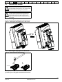
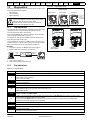
Removing the terminal covers
Both size 1 and size 2 drives are installed with one control terminal cover.
Figure 3-1 Removing the control terminal cover - Size 1 shown
Pozi Pz2
3.3.2
Removing the finger-guard and break-outs
Figure 3-2 Removing the finger-guard break-outs
1
2
All sizes
Place finger-guard on a flat solid surface and hit relevant break-outs with
hammer as shown (1). Continue until all required break-outs are removed
(2). Remove any flash / sharp edges once the break-outs are removed.
Quantum MP User Guide
Issue: A3
15
www.emersonct.com
Safety
Product Mechanical Electrical
Information Information Installation Installation
3.3.3
Getting
Started
Basic
Running the
SMARTCARD
Optimization
parameters
Motor
Operation
Onboard
PLC
Advanced Technical
UL
Diagnostics
Parameters
Data
Information
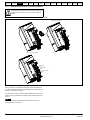
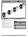
Installation and removal of a Solutions Module
Please power down the drive before removing / installing the
Solutions Module. Failure to do so may cause damage to
product
CAUTION
Figure 3-3 Installation and removal of the Solutions Module - Size 1 shown
Installing Solutions Module
Removing Solutions Module
B
A
A
Three Solutions Modules installed
Solution Module
in slot 1
Solution Module
in slot 2
SM-I/O 120V Module
in slot 3
To install the Solutions Module in either a Quantum MP size 1 or size 2
drive, press down in the direction shown above until it clicks into place.
To remove the Solutions Module, press inwards at the points shown (A)
and pull in the direction shown (B).
The drive has the facility for all three Solutions Module slots to be used
at the same time, as illustrated. The SM-I/O 120V module needs to stay
in Slot 3.
NOTE
It is recommended that the Solutions Module slots are used in the
following order: slot 2 and slot 1.
16
www.emersonct.com
Quantum MP User Guide
Issue: A3
Safety
Product Mechanical Electrical
Information Information Installation Installation
3.3.4
Getting
Started
Basic
Running the
SMARTCARD
Optimization
parameters
Motor
Operation
Onboard
PLC
Advanced Technical
UL
Diagnostics
Parameters
Data
Information
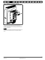
Installation and removal of a Keypad.
Figure 3-4 Removal and installation of a keypad - Size 1 shown
C
A
B
B
To fit the keypad in a Quantum MP size 1 or size 2, align the Keypad and
press gently in the direction shown until it clicks into position (A).
To remove, while pressing the tabs inwards (B), gently lift the keypad in
the direction indicated (C).
NOTE
The keypad can be installed / removed while the drive is powered up and
running a motor, providing that the drive is not operating in keypad
mode.
Quantum MP User Guide
Issue: A3
17
www.emersonct.com
Safety
Product Mechanical Electrical
Information Information Installation Installation
3.4
Getting
Started
Basic
Running the
SMARTCARD
Optimization
parameters
Motor
Operation
Onboard
PLC
Advanced Technical
UL
Diagnostics
Parameters
Data
Information
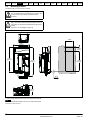
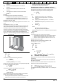
Mounting method
The Quantum MP can only be surface mounted.
WARNING
WARNING
If the drive has been used at high load levels for a period of
time, the heatsink can reach temperatures in excess of 70°C
(158°F). Human contact with the heatsink should be
prevented.
Many of the drives in this product range weigh in excess of
16kg (35lb). Use appropriate safeguards when lifting these
models.
See section 12.1.20 Weights on page 149
Figure 3-5 Surface mounting the size 1A drive
1
170mm
[6.69 in]
330mm
[12.99 in]
1
83mm
[3.25 in]
510mm
[20.09 in]
573mm
[22.56 in]
406mm
[15.98 in]
1
1
25mm
[0.97 in]
222mm
[8.72 in]
1. The two outer holes must be used for mounting the Quantum MP.
NOTE
With the SMARTCARD installed to the drive, the depth measurement
increases by 7.6mm (0.30 in).
18
www.emersonct.com
Quantum MP User Guide
Issue: A3
Safety
Product Mechanical Electrical
Information Information Installation Installation
Getting
Started
Basic
Running the
SMARTCARD
Optimization
parameters
Motor
Operation
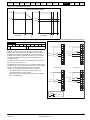
Figure 3-6 Surface mounting the size 2 drive
Onboard
PLC
Figure 3-7 Installing the mounting feet bracket - Size 1
2
19.25
L2
L1
Advanced Technical
UL
Diagnostics
Parameters
Data
Information
L3
GND
DANGER
HIGH VOLTAGE
9.00
24.75
Mounting Holes
0.438 Diameter
(8) places
33.00
DANGER
HIGH VOLTAGE
A+
A-
GND
1
The bottom mounting bracket (1) should be installed to the back plate
first. The drive should then be lowered onto the bracket and slotted in.
The top mounting bracket (2) should then be slotted into the drive and
the top holes marked for mounting (380mm [14.96 in] from the center of
the holes on the bottom mounting bracket). Once the holes have been
drilled, then fix the top mounting bracket accordingly.
Quantum MP User Guide
Issue: A3
19
www.emersonct.com
Safety
Product Mechanical Electrical
Information Information Installation Installation
3.5
Enclosure
3.5.1
Enclosure layout
Getting
Started
Basic
Running the
SMARTCARD
Optimization
parameters
Motor
Operation
Onboard
PLC
Advanced Technical
UL
Diagnostics
Parameters
Data
Information
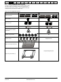
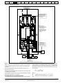
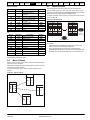
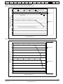
Please observe the clearances in the diagram below taking into account any appropriate notes for other devices / auxiliary equipment when planning
the installation.
Figure 3-8 Enclosure layout Size 1
AC supply, contactor,
line chokes
Enclosure
Ensure minimum clearances
are maintained for the drive.
Forced or convection air-flow
must not be restricted by any
object or cabling
≥100mm
(4in)
≥100mm
(4in)
≥100mm
(4in)
Note
For EMC compliance:
1) Power cabling must be at
least 100mm (4in) from the
drive in all directions
2) Ensure direct metal contact
at drive and filter mounting
points (any paint must be
removed)
Signal cables
Plan for all signal cables
to be routed at least
300mm (12in) from the
drive and any power cable
≥100mm
(4in)
External
controller
Armature
connection
cable
Field
connection cable
20
www.emersonct.com
Quantum MP User Guide
Issue: A3
Safety
Product Mechanical Electrical
Information Information Installation Installation
Getting
Started
Basic
Running the
SMARTCARD
Optimization
parameters
Motor
Operation
Onboard
PLC
Advanced Technical
UL
Diagnostics
Parameters
Data
Information
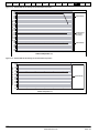
Figure 3-9 Enclosure layout size 2
AC supply, contactor,
line chokes
325 mm*
(13 in)
L2
L1
L3
Ensure minimum clearances
are maintained for the drive.
Forced convection air-flow
must not be restricted by any
object of cabling.
GND
DANGER
HIGH VOLTAGE
Note
For EMC compliance
1) Power cabling must be at
least 100 mm (4 in) from the
drive in all directions
2) Ensure direct metal contact
at drive and filter mounting
points (any paint must be
removed)
>100 mm
(4 in)
>100 mm
(4 in)
Signal cables
Plan for all signal cables
to be routed at least
300mm (12 in) from the
drive and any power cables
DANGER
HIGH VOLTAGE
A+
GND
A-
External
Controller
325 mm*
(13 in)
Armature
connection
cable
Field
conection cable
* Minimum wire bending space required by UL508 for final customer power connections.
3.5.2
Enclosure sizing
Refer to section 12.1.2 Power dissipation on page 147 for drive losses.
Add the dissipation figures for each drive that is to be installed in the
enclosure.
Add the power dissipation figures for each EMC filter that is to be
installed in the enclosure.
air by natural convection. The larger the surface area of the enclosure
walls, the better is the dissipation capability. Only the surfaces of the
enclosure that are not in contact with a wall or floor can dissipate heat.
Calculate the minimum required unobstructed surface area Ae for the
enclosure from:
A
Calculate the total heat dissipation (in Watts) of any other equipment to
be installed in the enclosure.
Add the figures of all of the above to get a total heat dissipation figure (in
Watts) for the equipment in the enclosure.
Calculating the size of a sealed enclosure
The enclosure transfers internally generated heat into the surrounding
Quantum MP User Guide
Issue: A3
e
P
= ---------------------------------------k(T
–T
)
int
ext
Where:
Ae
Unobstructed surface area in m2 (1 m2 = 10.9 ft2)
Text
Maximum expected temperature in oC outside the
21
www.emersonct.com
Safety
Product Mechanical Electrical
Information Information Installation Installation
Getting
Started
Basic
Running the
SMARTCARD
Optimization
parameters
Motor
Operation
•
•
enclosure
Maximum permissible temperature in oC inside the
Tint
Reducing the number of drives in the enclosure
Removing other heat-generating equipment
The dimensions of the enclosure are required only for accommodating
the equipment. The equipment is cooled by the forced air flow.
Power in Watts dissipated by all heat sources in the
enclosure
k
Calculate the minimum required volume of ventilating air from:
Heat transmission coefficient of the enclosure material
3kP
V = --------------------------T int – T ext
in W/m2/oC
Example
To calculate the size of an enclosure for the following:
•
•
•
Where:
Two QMP25A4 models operating under full load conditions
Maximum ambient temperature inside the enclosure: 40°C
Maximum ambient temperature outside the enclosure: 30°C
Dissipation of each drive: 125W
Dissipation from other heat generating equipment in the enclosure. 11W
(max).
Total dissipation: 2 x (125 + 11) = 272W
Air-flow in m3 per hour (1 m3/hr = 0.59 ft3/min)
Maximum expected temperature in °C outside the
enclosure
Maximum permissible temperature in °C inside the
enclosure
Power in Watts dissipated by all heat sources in the
enclosure
Po
Ratio of ------Pl
V
Text
Tint
P
k
The enclosure is to be made from painted 2mm (0.079in) sheet steel
having a heat transmission coefficient of 5.5 W/m2/oC. Only the top,
front, and two sides of the enclosure are free to dissipate heat.
The value of 5.5 W/m2/ºC can generally be used with a sheet steel
enclosure (exact values can be obtained by the supplier of the material).
If in any doubt, allow for a greater margin in the temperature rise.
Figure 3-10
Advanced Technical
UL
Diagnostics
Parameters
Data
Information
Calculating the air-flow in a ventilated enclosure
enclosure
P
Onboard
PLC
Enclosure having front, sides and top panels free to
dissipate heat
Where:
P0 is the air pressure at sea level
PI is the air pressure at the installation
Typically use a factor of 1.2 to 1.3, to allow also for pressure-drops in
dirty air-filters.
Example
To calculate the size of an enclosure for the following:
•
•
•
Three QMP45A4 models operating under full load conditions
Maximum ambient temperature inside the enclosure: 40°C
Maximum ambient temperature outside the enclosure: 30°C
Dissipation of each drive: 168W
Dissipation from other heat generating equipment. 15 W
H
Total dissipation: 3 x (168 + 15) = 549W
Insert the following values:
Tint
40°C
Text
30°C
k
1.3
P
549W
D
W
Then:
3 × 1.3 × 549
V = ---------------------------------40 – 30
Insert the following values:
Tint
40°C
Text
30°C
k
5.5
P
272W
= 214.1 m3/hr (126.3 ft3 /min) (1 m3/ hr = 0.59 ft3/min)
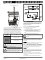
3.6
Heatsink fan operation
Quantum MP drive rated 75A and above are ventilated by internally
The minimum required heat conducting area is then:
272W
A e = --------------------------------5.5 ( 40 – 30 )
supplied fans.
Ensure the minimum clearances around the drive are maintained to
allow the air to flow freely.
= 4.945 m2 (53.90 ft2) (1 m2 = 10.9 ft2)
Estimate two of the enclosure dimensions - the height (H) and depth (D),
for instance. Calculate the width (W) from:
A e – 2HD
W = -------------------------H+D
Inserting H = 2m and D = 0.6m, obtain the minimum width:
4.945 – ( 2 × 2 × 0.6 )
W = ----------------------------------------------------2 + 0.6
The drive controls the fan operation based on the temperature of the
heatsink and the drives thermal model system.
3.7
IP Rating (Ingress Protection)
An explanation of IP Rating is provided in section 12.1.11 IP Rating on
page 148.
=0.979 m (38.5 in)
If the enclosure is too large for the space available, it can be made
smaller only by attending to one or all of the following:
•
Reducing the ambient temperature outside the enclosure, and/or
applying forced-air cooling to the outside of the enclosure
22
www.emersonct.com
Quantum MP User Guide
Issue: A3
Safety
Product Mechanical Electrical
Information Information Installation Installation
Getting
Started
Basic
Running the
SMARTCARD
Optimization
parameters
Motor
Operation
3.8
Electrical terminals - Size 1
3.8.1
Location of the power and ground terminals
Figure 3-11
Onboard
PLC
Advanced Technical
UL
Diagnostics
Parameters
Data
Information
Location of the power and ground terminals
DB+,DB-,SR1, and SR2 connection
5 mm
A1, A2
connection
GND, L1, L2, L3
connection
QMP45 / 75 drives
5 mm
QMP45 / 75
drives
5 mm
QMP75 / 155 drives
3/8 inch
QMP155 / 210
drives
5/16 inch
Control and
encoder
connection
2.5 mm
Tach
connection
3.5 mm
MP 10, 120 Vac
I/O connection
5 mm
5 mm
Field
connector
Auxiliary
connector
3.8.2
To avoid a fire hazard and maintain validity of the UL listing,
adhere to the specified tightening torques for the power and
ground terminals. Refer to the following tables.
WARNING
3.8.3
Torque settings
Table 3-1
Model
All
Relay
connector
Table 3-3
Terminal sizes and torque settings
Connection type
Torque setting
Plug-in terminal block
0.5 Nm 0.4 lb ft
Drive power (L1, L2, L3, and GND) terminals
Model
Connection type
Torque setting
QMP45A4(R)
2-14 AWG Slot Screw Lug
4-5.6 Nm 2.9-4.2 lb ft
QMP75A4(R)
2-14 AWG Slot Screw Lug
4-5.6 Nm 2.9-4.2 lb ft
QMP155A4(R)
5/16” Socket Lug
31 Nm 23 lb ft
QMP210A4(R)
5/16” Socket Lug
31 Nm 23 lb ft
Table 3-4
Control terminal data
3.5 mm
3.5 mm
Drive power (A1 and A2) terminals
Model
Connection type
Torque setting
QMP45A4(R)
2-14 AWG Slot Screw Lug
4-5.6 Nm 2.9-4.2 lb ft
QMP75A4(R)
2-14 AWG Slot Screw Lug
4-5.6 Nm 2.9-4.2 lb ft
Auxiliary and Field terminal data
QMP155A4(R)
3/8” Socket Lug
42 Nm 31 lb ft
Model
Connection type
Torque setting
QMP210A4(R)
3/8” Socket Lug
42 Nm 31 lb ft
All
Terminal block
0.5 Nm 0.4 lb ft
Table 3-2
Quantum MP User Guide
Issue: A3
23
www.emersonct.com
Safety
Product Mechanical Electrical
Information Information Installation Installation
Table 3-5
Getting
Started
Basic
Running the
SMARTCARD
Optimization
parameters
Motor
Operation
Dynamic Braking Resistor (DB+ and DB-) terminals
Model Connection type
All
Slotted lug
Table 3-6
Torque setting
Wire gauge
Advanced Technical
UL
Diagnostics
Parameters
Data
Information
Suppression Resistor (SR+ and SR-) terminals
Model Connection type
Wire gauge
Torque setting
Nm
lb ft
14-10 AWG
4
2.92
14-10 AWG
4
2.92
8 AWG
4.5
3.33
8 AWG
4.5
3.33
6-4 AWG
5
3.75
2 AWG
5.6
4.17
All
3.9
Electrical terminals - Size 2
3.9.1
Location of the power and ground terminals
Figure 3-12
Onboard
PLC
Slotted lug
Nm
lb in
6-4 AWG
5
3.75
2 AWG
5.6
4.17
Location of the power and ground terminals
L2
L1
FIG 4A
L3
L2
L1
L3
GND
GND
DANGER
HIGH VOLTAGE
DANGER
HIGH VOLTAGE
A+
A2
3.9.2
GND
A-
A1
Terminal sizes and torque settings
GND
3.9.3
120Vac Logic
Terminals
Torque settings
Table 3-7
To avoid a fire hazard and maintain validity of the UL listing,
adhere to the specified tightening torques for the power and
ground terminals. Refer to the following tables.
Drive control, status relay and encoder terminal data
Model
All
Connection type
Torque setting
Plug-in terminal block
0.5 Nm 0.4 lb ft
WARNING
24
www.emersonct.com
Quantum MP User Guide
Issue: A3
Safety
Product Mechanical Electrical
Information Information Installation Installation
Table 3-8
Getting
Started
Basic
Running the
SMARTCARD
Optimization
parameters
Motor
Operation
Drive auxiliary and machine armature terminal data
Table 3-9
Onboard
PLC
Advanced Technical
UL
Diagnostics
Parameters
Data
Information
Drive 120 Vac logic terminals
Model
Connection type
Torque setting
Model
Connection type
Torque setting
All
Terminal block
0.5 Nm 0.4 lb ft
All
Terminal block
0.79 Nm 0.58 lb ft
Table 3-10
Drive power stage terminals
AC line
Model
Max
wire size
Conn/Lug
QMP350A4(R)
2
QMP400A4(R)
2
QMP550A4(R)
350 MCM
QMP700A4(R)
3.10
2
DC armature
Torque
setting
Max
wire size
Conn/Lug
250 MCM
2
2
22.91 lb ft
350 MCM
3
2
3
Dynamic braking resistor
Torque
setting
Max
wire size
250 MCM
22.91 lb ft
N/A
Conn/Lug
1
1
N/A
Torque
setting
22.91 lb ft
N/A
Routine maintenance
The drive should be installed in a cool, clean, well ventilated location.
Contact of moisture and dust with the drive should be prevented.
Regular checks of the following should be carried out to ensure drive /
installation reliability are maximized:
Environment
Ambient temperature
Ensure the enclosure temperature remains at
or below maximum specified
Dust
Ensure the drive remains dust free – check that
the heatsink and drive fan are not gathering
dust. The lifetime of the fan is reduced in dusty
environments.
Moisture
Ensure the drive enclosure shows no signs of
condensation
Enclosure
Enclosure door
filters
Ensure filters are not blocked and that air is free
to flow
Electrical
Screw connections
Ensure all screw terminals remain tight
Crimp terminals
Ensure all crimp terminals remains tight –
check for any discoloration which could indicate
overheating
Cables
Check all cables for signs of damage
Quantum MP User Guide
Issue: A3
25
www.emersonct.com
Safety
Product
Mechanical Electrical
Information Information Installation Installation
4
Getting
Started
Basic
Running the
SMARTCARD
Optimization
parameters
Motor
Operation
Onboard
PLC
Advanced Technical
UL
Diagnostics
Parameters
Data
Information
Electrical Installation
Many cable management features have been incorporated into the
product and accessories, this chapter shows how to optimize them. Key
features include:
•
•
•
EMC compliance
Product rating, fusing and cabling information
External suppressor resistor details (selection / ratings)
Electric shock risk
The voltages present in the following locations can cause
severe electric shock and may be lethal:
WARNING
WARNING
•
•
•
AC supply cables and connections
DC cables, and connections
Many internal parts of the drive, and external option
units
Unless otherwise indicated, control terminals are single
insulated and must not be touched.
Isolation device
The AC supply must be disconnected from the drive using
an approved isolation device before any cover is removed
from the drive or before any servicing work is performed.
STOP function
The STOP function does not remove dangerous voltages
from the drive, the motor or any external option units.
WARNING
WARNING
Drives are suitable for use on supplies of installation
category III and lower, according to IEC60664-1. This means
they may be connected permanently to the supply at its
origin in a building, but for outdoor installation additional
over-voltage suppression (transient voltage surge
suppression) must be provided to reduce category IV to
category III.
26
www.emersonct.com
Quantum MP User Guide
Issue: A3
Safety
Product
Mechanical Electrical
Information Information Installation Installation
Quantum MP User Guide
Issue: A3
Getting
Started
Basic
Running the
SMARTCARD
Optimization
parameters
Motor
Operation
Onboard
PLC
Advanced Technical
UL
Diagnostics
Parameters
Data
Information
27
www.emersonct.com
Safety
Product
Mechanical Electrical
Information Information Installation Installation
Getting
Started
Basic
Running the
SMARTCARD
Optimization
parameters
Motor
Operation
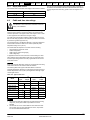
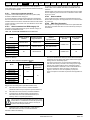
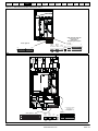
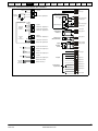
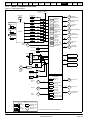
4.1
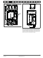
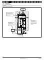
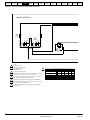
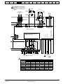
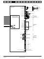
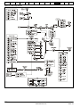
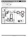
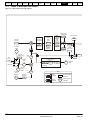
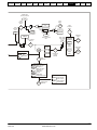
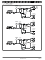
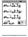
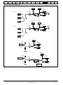
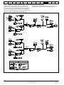
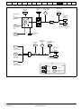
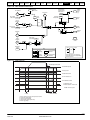
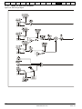
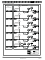
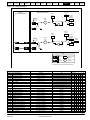
Electrical connections/ Power connections
4.1.1
AC and DC connections
Onboard
PLC
Advanced Technical
UL
Diagnostics
Parameters
Data
Information
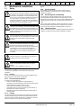
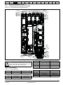
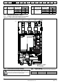
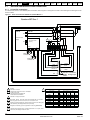
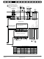
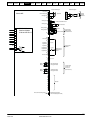
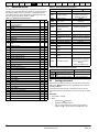
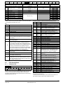
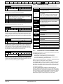
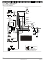
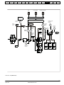
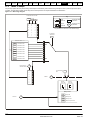
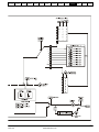
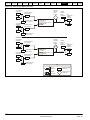
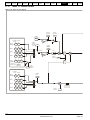
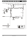
To understand the function of the different power connections, refer to Figure 4-1 and Figure 4-2 for size 1 drives and Figure 4-3 and Figure 4-4 for
the size 2 drives.
Figure 4-1 Power connections for 480V drive, Quantum MP size 1
Quantum MP Size 1
MP19
X1 X2 E1 E3
MP18
120 V
Contactor Power
Supply
2
F3
Contactor Control
Circuitry
30 V
A B C D E F G H I J
CON 1
PL1
Brake
Contactor
BC
BLACK
BLACK
MC
Motor
Contactor
+-
RED
RED
+-
BLACK
5
GRAY
4
9
PURPLE
8
BLUE
7
WHITE
ORANGE 3
YELLOW
RED
2
3
1
480 VAC connections
shown. Configure per
Table 1.
Contactor Control Signal
1
2
NOTES:
See Table 2 for values.
3
TABLE 1 - T1 TRANSFORMER CONNECTIONS BY SUPPLY VOLTAGE
TRANSFORMER
Quantum MP control power fuse F3 - All Models:
CT P/N = 212011-05
Cooper-Bussmann P/N FNQ-R-1/2
Ferraz-Shawmut P/N ATQR1/2
3
See Table 1 for proper connection.
4
Motor Field - 8A max. Connection shown is for 300 VDC Field. For 150 VDC Remove jumper from F2 to F3 and connect F1 to F3 and F2 to F4
5
Enable Input must be pulled high (+24V) as shown for drive to enter Ready "rdy"
state. Otherwise, drive display will show "inh" (Inhibited).
7
Designators in brackets [ ] refer to regenerative models only (QMPXXXA4R).
9
Optional motor thermistor input if not used set parameter 7.15 = 6 (Volt). When
fault occurs, drive display will show the fault.
SUPPLY VOLTAGE - L1/L3 50/60 Hz
LEAD COLOR
PIN
208V
240V
RED
YELLOW
ORANGE
GRAY
BLACK
WHITE
BLUE
PURPLE
1
2
3
4
5
7
8
9
B
F
A
E
G
J
H
I
B
F
A
E
G
J
I
H
28
www.emersonct.com
380V
416V
B
D
E
C
G
J
H
I
TERMINAL
B
D
C
E
G
J
H
I
480V
B
D
C
E
G
J
I
H
Quantum MP User Guide
Issue: A3
Safety
Product
Mechanical Electrical
Information Information Installation Installation
3
Getting
Started
Basic
Running the
SMARTCARD
Optimization
parameters
Motor
Operation
Onboard
PLC
Advanced Technical
UL
Diagnostics
Parameters
Data
Information
CAUTION:Verify Control
Transformer is configured per
Table 1 before applying input
voltage!
150 VDC
Input Voltage
208/240/380/416/480 VAC
50/60 Hz
Motor Field
4
Motor Armature
F1
F2
F3
F4
Connection
300 VDC F4
Connection
F3
F6
7
M
F1
F2
External
Suppression
Resistor
Dynamic Brake
Resistor
L1 L2 L3
F4
A1 [A2]
A2 [A1]
A1 DB- DB+ A2
F8
1
SR1
SR2
DC
- BC + Protection
(Armature)
Fuse
F2
1
Semiconductor
(Line) Fuses
A2 MA2 MA1 A1
[A1] [MA1] [MA2] [A2]
F+
PE
1 2 3 4 5 6 7 8 9 10 11 12
41 42
22 31
Tach
Enable
0V
0V
Analog Input 3
+ -
+24
SM-IO-120V Solutions Module
in Mentor MP Slot 3
Contactor Control 2-way plug
located near drive PE terminal
PL11 on Mentor MP90 PCB
Drive Enable
Mentor MP Size 1
8 11 3
+10 V, 10 mA
F-
Analog Input 1 Inverting Input
L12 L11
TAB 2
on MP14
PCB
E1 E3 L1 L2 L3
TAB 1
on MP14
Analog Input 1 Non-Inverting Input PCB
MC
6
5 4
N/C
N/C
X1 X2 Q1 Q2 Q3 Q4 Q5 Q6 Q7 Q8 Q9 Q10 Q11Q12
MP10 User Interface Board
TB1
TB2
TB4
TB3
C1 C2 C3 C4 C5 C6 C7 C8 C9 C10 C11 C12 C13 C14 C15 C16
Rev
E-Stop
Motor
Thermal
Stop
Run
Jog
Fwd Reset Drive
ON
Interlocks
5
Motor
Speed Pot
Thermistor
(Optional)
PR
9
7.15
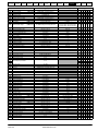
1
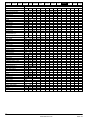
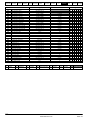
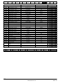
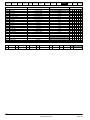
TABLE 2 - QUANTUM MP FUSES
MODEL
LINE FUSES F4, F6, F8 - 500V
ARMATURE FUSE F2 - 700V (SEE NOTE )
MFG P/N
RATING
CT P/N
MFG P/N
RATING
FWH-90B
90A
FWP-90B
90A
QMP45A4
3701-500090
3701-700090
70A
80A
QMP45A4R
A50QS70-4
A70QS80-4
FWH-150B
150A
FWP-125A
125A
QMP75A4
3701-700125 A70QS125-4
125A
QMP75A4R 3701-500125 AQ50QS125-4 125A
FWH-250A
250A
FWP-250A
250A
QMP155A4
3701-500250
3701-700250
250A
250A
QMP155A4R
A50QS250-4
A70QS250-4
FWH-350A
350A
FWP-350A
350A
QMP210A4
3701-700350 A70QS350-4
350A
350A
QMP210A4R 3701-500350 A50QS350-4
NOTE: ARMATURE FUSE IS ONLY USED ON "R" MODEL FOUR QUADRANT DRIVES
Quantum MP User Guide
Issue: A3
CT P/N
29
www.emersonct.com
Safety
Product
Mechanical Electrical
Information Information Installation Installation
Getting
Started
Basic
Running the
SMARTCARD
Optimization
parameters
Motor
Operation
Onboard
PLC
Advanced Technical
UL
Diagnostics
Parameters
Data
Information
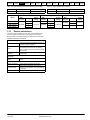
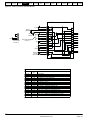
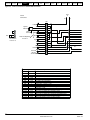
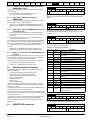
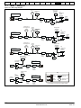
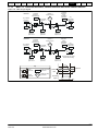
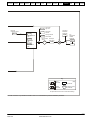
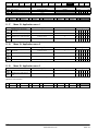
Figure 4-2 Control connections, Quantum MP size 1
MP10 User Interface Board
C1
E-Stop
C2
System
Interlocks
C5
C6
Run
C4
Motor
Thermal
Two wire Run
Pr 6.40 = 0
C5
Stop
C7
C8
X1
X2
Q1
Q2
Q3
Q4
Q5
Q6
Q7
Q8
Q9
Q10 N/C
Q11
Q12
C3
C6
C7
Run
Three wire Stop/Run
Pr 6.40 = 1
C8
C9
Jog
C10
C11
Rev
Fwd
Reset
Drive ON
120 VAC
30 VA max.
C12
C13
C14
C15
C16
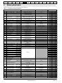
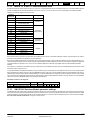
Programming Notes: Changes to Mentor MP USA Default Values
Parameter
Quantum MP
Value
5.16
6.40
8.22
8.23
8.24
8.26
9.04
9.05
9.09
9.10
9.37
17.21
17.22
17.23
17.24
17.25
17.28
1
1
0.00
0.00
0.00
0.00
17.06
1
0.1
10.32
1
6.39
6.34
6.31
6.33
10.33
6.55
Description
DC Contactor
Enable sequencer latching
T25 digital I/O 2 source/ destination
T26 digital I/O 3 source/ destination
T27 digital input 4 destination
T29 digital input 6 destination
Logic function 1 source 1
Logic function 1 source 1 invert
Logic function 1 delay
Logic function 1 destination (External Trip)
Logic block 1 mode
SM-IO-120V T1 digital input 1 destination (Not stop)
SM-IO-120V T2 digital input 2 destination (Run)
SM-IO-120V T4 digital input 3 destination (Jog)
SM-IO-120V T5 digital input 4 destination (Forward/reverse)
SM-IO-120V T7 digital input 5 destination (Drive reset)
SM-IO-120V Relay 2 source (Contactor enable)
30
www.emersonct.com
Quantum MP User Guide
Issue: A3
Safety
Product
Mechanical Electrical
Information Information Installation Installation
Getting
Started
Basic
Running the
SMARTCARD
Optimization
parameters
Motor
Operation
Onboard
PLC
Advanced Technical
UL
Diagnostics
Parameters
Data
Information
Differential Signal
Single Ended Signal
Mentor MP
+10 (10mA)
Non-Inverting Input
Inverting Input
0V
Analog Input 2
Analog Input 3
Analog Output 1
1 2 3 4 5 6 7 8 9 10 11 12
SM-IO-120V
Solutions Module
in Mentor MP Slot 3
Analog Output 2
7
Motor Thermistor
9
10
0V
21
22
23
24
25
26
27
28
29
30
31
Digital I/O 2
Digital I/O 3
Digital Input 4
Digital Input 5
Digital Input 6
0V
Drive Enable
+
Status
Relay 1
41
42
52
53
Speed
62
63
Programmable
Analog Outputs
±10V ±35mA max.
At Speed
Programmable
Digital I/O
Analog 1
Analog 2
Analog Input 1/
Analog Input 2
Select
Tachometer
Drive OK Indicator
Re-programmable
51
Status
Relay 2
Analog
Speed
Referenc
Analog Speed Reference 2
8
11
0V
Relay 2
6
3
6
3
0V
Digital I/O 1
4
5
Speed Pot
Armature Current
+24V Output
N/C
4
5
Contact rating
240 Vac 5A
30 Vdc 5 A
(Non-Inductive)
Contactor Enable
Re-programmable
61
A
A\
B
B\
Encoder
Z
Z\
+
0
Drive Commissioning Output
Quantum MP User Guide
Issue: A3
Instantaneous Armature
Current Feedback (Test Point)
31
www.emersonct.com
Safety
Product
Mechanical Electrical
Information Information Installation Installation
Getting
Started
Basic
Running the
SMARTCARD
Optimization
parameters
Motor
Operation
Onboard
PLC
Advanced Technical
UL
Diagnostics
Parameters
Data
Information
Figure 4-3 Power connections for Quantum MP size 2 drives
Quantum MP Size 2
E1
E3
F3B
2
F3A
B
E3F
H8
H7
H6 H5
H4
230V
208V
190V
E1F
3
A
H3
H2
H1
230V
208V
190V
BR1
T1
X1
1
115V
MC
X2
NOTES:
See Table 2 for values.
2
Quantum MP control power fuses
F3A, F3B - Ferraz ATQR1
Bussmann FRQR1
3
See Table 1 for proper connection.
3
TABLE 1 - T1 TRANSFORMER CONNECTIONS BY SUPPLY VOLTAGE
TRANSFORMER
LEAD
4
Motor Field - 20A max. Connection shown is for 300 VDC Field. For 150 VDC Remove jumper from F2 to F3 and connect F1 to F3 and F2 to F4
5
Enable Input must be pulled high (+24V) as shown for drive to enter Ready "rdy"
state. Otherwise, drive display will show "inh" (Inhibited).
7
Designators in brackets [ ] refer to regenerative models only (QMPXXXA4R).
9
Optional motor thermistor input if not used set parameter 7.15 = 6 (Volt). When
fault occurs, drive display will show the fault.
10
N.C. MC contact (Dynamic Braking) is only supplied on Models QMP350A4
and QMP400A4.
E1F
E3F
JUMPER A
JUMPER B
32
www.emersonct.com
SUPPLY VOLTAGE - L1/L3 50/60 Hz
208V
240V
380V
416V
480V
H2
H1
H3
H2
H1
H8
H8
H8
H8
H8
H4-H8 H4-H8 H4-H7 H4-H6 H4-H5
H2-H6 H1-H5 H4-H7 H4-H6 H4-H5
TERMINAL
Quantum MP User Guide
Issue: A3
Safety
Product
Mechanical Electrical
Information Information Installation Installation
3
Getting
Started
Basic
Running the
SMARTCARD
Optimization
parameters
Motor
Operation
Onboard
PLC
Advanced Technical
UL
Diagnostics
Parameters
Data
Information
CAUTION: Verify Control
Transformer is configured per
Table 1 before applying input
voltage!
4
Motor Field
Motor Armature
F6
External
Suppression
Resistor
Dynamic Brake
Resistor
F8
1
7
M
300 VDC
Connection
F4
A1 [A2]
A2 [A1]
150 VDC
Connection
Input Voltage
208/240/380/416/480 VAC
50/60 Hz
10
Semiconductor
(Line) Fuses
- MC +
DC
Protection
(Armature)
Fuse
F2
1
+10 V, 10 mA
Analog Input 1 Inverting Input
0V
0V
+ -
+24
Relay 2
Analog Input 3
SM-IO-120V Solutions Module
in Mentor MP Slot 3
Drive Enable
Mentor MP Size 2
Analog Input 1 Non-Inverting Input
TAB 2
on MP14
PCB
TAB 1
on MP14
PCB
MC
N/C
TB1
Rev
E-Stop
Motor
Thermal
Stop
Run
Jog
Fwd
Reset Drive
ON
System Interlock(s)
Tach
Enable
5
Motor
Speed Pot
Thermistor
(Optional)
PR
9
7.15
1
MODEL
TABLE 2 - QUANTUM MP SIZE 2 FUSES
LINE FUSES F4, F6, F8 - 500V
ARMATURE FUSE F2 - (SEE NOTE )
MFG P/N
RATING
CT P/N
MFG P/N
CT P/N
FWH-450A
N/A
450A,500V
N/A
QMP350A4
3701-545000
A50QS450-4
450A,700V
FWP-450A
A70QS450-4
3701-745000
QMP350A4R 3701-745001
FWH-600A
600A,500V
N/A
N/A
QMP400A4
3701-560000
A50QS600-4
FWP-600A
3701-760000
600A,700V
A70QS600-4
QMP400A4R 3701-760001
FWH-700A
700A,500V
N/A
N/A
QMP550A4
3701-570000
A50QS700-4
3701-770000
FWP-700A
700A,700V
A70QS700-4
QMP550A4R 3701-770001
1000A,500V
FWH-1000A
N/A
N/A
QMP700A4
3701-511001
900A,500V
A50QS900-4
(2) A70QS500-4
3701-790000
FWP-900A
500A,700V
QMP700A4R 3701-750001
NOTE: ARMATURE FUSE IS ONLY USED ON "R" MODEL FOUR QUADRANT DRIVES
Quantum MP User Guide
Issue: A3
RATING
N/A
450A,700V
N/A
600A,700V
N/A
700A,700V
N/A
900A,700V
33
www.emersonct.com
Safety
Product
Mechanical Electrical
Information Information Installation Installation
Getting
Started
Basic
Running the
SMARTCARD
Optimization
parameters
Motor
Operation
Onboard
PLC
Advanced Technical
UL
Diagnostics
Parameters
Data
Information
Figure 4-4 Control connections for Quantum MP size 2 Drives
From
T1
Control
Connections
X1
X2
TB1
C1
E-Stop
C2
System
Interlocks
C5
C6
Run
C3
C4
Motor
Thermal
C5
Stop
C6
C7
C8
Two wire Run
Pr 6.40 = 0
C7
Run
Three wire Stop/Run
Pr 6.40 = 1
C8
C9
Jog
C10
C11
Rev
Fwd
Reset
Drive ON
120 VAC
30 VA max.
C12
C13
N/C
C14
C15
C16
Programming Notes: Changes to Mentor MP USA Default Values
Parameter
Quantum MP Value
5.16
6.40
8.22
8.23
8.24
8.26
9.04
9.05
9.09
9.10
9.37
17.21
17.22
17.23
17.24
17.25
17.28
1
1
0.00
0.00
0.00
0.00
17.06
1
0.1
10.32
1
6.39
6.34
6.31
6.33
10.33
6.55
Description
DC Contactor
Enable sequencer latching
T25 digital I/O 2 source/ destination
T26 digital I/O 3 source/ destination
T27 digital input 4 destination
T29 digital input 6 destination
Logic function 1 source 1
Logic function 1 source 1 invert
Logic function 1 delay
Logic function 1 destination (External Trip)
Logic block 1 mode
SM-IO-120V T1 digital input 1 destination (Not stop)
SM-IO-120V T2 digital input 2 destination (Run)
SM-IO-120V T4 digital input 3 destination (Jog)
SM-IO-120V T5 digital input 4 destination (Forawrd/reverse)
SM-IO-120V T7 digital input 5 destination (Drive reset)
SM-IO-120V Relay 2 source (Contactor enable)
34
www.emersonct.com
Quantum MP User Guide
Issue: A3
Safety
Product
Mechanical Electrical
Information Information Installation Installation
Getting
Started
Basic
Running the
SMARTCARD
Optimization
parameters
Motor
Operation
Onboard
PLC
Advanced Technical
UL
Diagnostics
Parameters
Data
Information
Single Ended Signal
+10 (10mA)
Mentor MP
Non-Inverting Input
Inverting Input
0V
Analog Input 2
Analog Input 3
Analog Output 1
1 2 3 4 5 6 7 8 9 10 11 12
SM-IO-120V
Solutions Module
in Mentor MP Slot 3
Analog Output 2
7
Analog Speed Reference 2
8
Motor Thermistor
9
10
11
0V
21
22
23
24
25
26
27
28
29
30
31
0V
Digital I/O 2
Digital I/O 3
Digital Input 4
Digital Input 5
Digital Input 6
0V
Drive Enable
+
Status
Relay 1
41
42
52
53
Speed
62
63
Programmable
Analog Outputs
±10V ±35mA max.
At Speed
Programmable
Digital I/O
Analog 1
Analog 2
Analog Input 1/
Analog Input 2
Select
Tachometer
Drive OK Indicator
Re-programmable
51
Status
Relay 2
Analog
Speed
Reference 1
6
3
6
3
0V
Digital I/O 1
Relay 2
Speed Pot
Armature Current
+24V Output
N/C
4
5
Differential Signal
4
5
Contactor Enable
Re-programmable
Contact Rating
240 VAC 5A
30 VDC 5A
(Non-Inductive)
61
A
A\
B
B\
Encoder
Z
Z\
+
0
Drive Commissioning Output
Quantum MP User Guide
Issue: A3
Instantaneous Armature
Current Feedback (Test Point)
35
www.emersonct.com
Safety
Product
Mechanical Electrical
Information Information Installation Installation
4.2
Getting
Started
Basic
Running the
SMARTCARD
Optimization
parameters
Motor
Operation
Ground connections
Figure 4-6
Onboard
PLC
Advanced Technical
UL
Diagnostics
Parameters
Data
Information
Location of ground connection, Size 2
The drive must be connected to the system ground of the AC supply.
The ground wiring must conform to local regulations and codes of
practice.
Ground
Connection
Where there is a possibility of temporary condensation or
corrosion occurring, the ground connection should be
protected from corrosion by suitable jointing compound.
L2
L1
L3
GND
DANGER
HIGH VOLTAGE
WARNING
Ground loop impedance
WARNING
The ground loop impedance must conform to the
requirements of local safety regulations.
The drive must be grounded by a connection capable of
carrying the prospective fault current until the protective
device (fuse, etc,) disconnects the AC supply.
The ground connections must be inspected and tested at
appropriate intervals.
Figure 4-5 Location of ground connection, Size 1
Ground
Connection
DANGER
HIGH VOLTAGE
A+
A-
GND
Ground
Connection
4.3
AC supply requirements
The standard drive is rated for a nominal supply voltage up to 480 Vrms.
4.3.1
Supply types
Drives are suitable for use with any supply type, i.e. TN-S, TN-C-S, TT,
IT, with grounding at any potential, i.e. neutral, centre or corner
(“grounded-delta”).
4.3.2
MOV ground disconnect
The facility for disconnecting the link between varistors and ground is
provided for special circumstances, where a sustained high voltage may
be present between lines and ground, for example during a high
potential test or in certain situations with IT supplies and multiple
generators. If the link is disconnected then the immunity of the drive to
high voltage impulses is reduced. It is then only suitable for use with
supplies having overvoltage category II, i.e. not for connection at the
origin of the low voltage supply within a building.
36
www.emersonct.com
Quantum MP User Guide
Issue: A3
Safety
Product
Mechanical Electrical
Information Information Installation Installation
Getting
Started
Basic
Running the
SMARTCARD
Optimization
parameters
Motor
Operation
Figure 4-7 Removing the MOV ground connection, Size 1
Onboard
PLC
Advanced Technical
UL
Diagnostics
Parameters
Data
Information
necessary where a dedicated transformer is used to supply the drive.
The following recommendations for added line inductance, have been
calculated based on the power drive systems standard: EN618003:2004 “Adjustable speed electrical power drive systems – Part 3: EMC
requirements and specific test methods”.
5
3
NOTE
The current ratings specified in Table 4-2 is for typical motor currents
where the motor current ripple is no more than 50% of drive rating.
1
4
Table 4-2
Minimum values of Ladd and inductor current rating 480V supply
2
Ladd
Model
The method for disconnecting the MOV ground connection is shown
below:
1.
2.
3.
4.
Remove the M4 x 16 screw using T20 Torx driver.
Remove the M4 x 12 screw using T20 Torx driver.
Remove the plate.
Re-fit the M4 x 12 screw using T20 Torx driver and tighten to a
torque of 0.6 Nm (0.44 Ib ft).
5. Fit a M4 x 16 nylon screw (not supplied) and tighten to a torque of
0.25 Nm (0.18 Ib ft).
Maximum
current rating
µH
A
A
QMP45A4(R)
260
38
40
QMP75A4(R)
260
63
67
QMP155A4(R)
190
130
139
QMP210A4(R)
140
176
188
QMP350A4(R)
85
293
313
QMP400A4(R)
71
351
375
QMP550A4(R)
54
460
492
QMP700A4(R)
43
586
626
4.5
Auxiliary AC supply and connections
Table 4-3
The M4 x 16 screw (1) should not be re-used if the plate (3)
is not re-installed. Instead a nylon screw should be used.
Typical
current rating
Terminal functions
Terminals
Function
E1, E3
Supply for control electronics and field controller. These
terminals should be in phase with the mains supply to the
drive. E1 and E3 are pre-wired at the factory to the main
supply lines L1 and L3. If it is necessary to separate the
auxiliary and main supplies, see section 4.6
L11, L12
Field on / off. When L11 and L12 are open the supply is
disconnected to the field regulator so there will be no field
current.
WARNING
Figure 4-8 Removing the MOV ground connection, Size 2
F+, F-
Field supply to the motor.
These terminals are used to provide feedback from the
motor armature terminals. This is required when there is a
contactor in the main DC armature connection as is the
case with Quantum MP. When the contactor is opened
MA1, MA2
the drive will still be receiving armature feedback. This
allows the field regulator to function correctly when the
contactor is open. MA1 and MA2 are pre-wired at the
factory to the appropriate armature terminals.
1
The method for disconnecting the MOV ground connection is shown
below:
Table 4-4
One phase line to line supply
Specification
Value
1. Remove the M4 x 30 screw using T20 Torx driver
If re-fitting the M4 x 30 screw using T20 Torx driver, the screw must be
tightened to a torque of 2.5Nm (1.84 lb ft).
Max nominal supply
Tolerance
+10%
4.3.3
Min nominal supply
208 V
Tolerance
-10%
SCR bridge AC supply
Table 4-1
Three phase AC supply
Specification
Product voltage variant
480V
Max nominal supply
480V
Tolerance
+10%
Min nominal supply
24V
Tolerance
-20%
4.4
480 V
Each drive has an on-board field controller with the following current
ratings.
Line reactors
The Quantum MP, in common with all naturally commutated SCR drives,
causes voltage notches at the input supply terminals. In order to avoid
disturbance to other equipment using the same supply, the addition of
external line inductance is strongly recommended in order to restrict the
depth of the notches imposed on the shared supply. This is generally not
Quantum MP User Guide
Issue: A3
37
www.emersonct.com
Safety
Product
Mechanical Electrical
Information Information Installation Installation
Table 4-5
Basic
Running the
SMARTCARD
Optimization
parameters
Motor
Operation
Current ratings
Model
Table 4-6
Maximum continuous field current rating
A
QMP45A4(R)
QMP75A4(R)
QMP155A4(R)
QMP210A4(R)
8
QMP350A4(R)
QMP400A4(R)
QMP550A4(R)
QMP700A4(R)
20
4.5.1
Getting
Started
Supply Voltage - L1/L3 50/60 Hz
208 V 240 V 380 V 415 V 480 V
Lead Color
Pin
Red
1
B
B
B
B
B
Yellow
2
F
F
D
D
D
Orange
3
A
A
E
C
C
Gray
4
E
E
C
E
E
Black
5
G
G
G
G
G
White
7
J
J
J
J
J
Blue
8
H
I
H
H
I
Purple
9
I
H
I
I
H
Terminals
Supply requirements
Frequency range: 48 to 65 Hz (maximum rate of frequency change is 7
Hz/s)
Separating the Auxiliary Supply
The Quantum MP drive is delivered from the factory with the auxiliary
supply terminals E1 and E3 are pre-wired to the drive AC power
terminals L1 and L3. This is adequate for most installations. If it is
necessary to power the auxiliary supply from a separate source, the
following steps must be taken:
1. Ensure that the main AC supply and any other hazardous energy
sources are turned off and locked out before attempting to remove
the Quantum drive cover or auxiliary wiring.
2. Wait for 10 minutes after turning off the electrical supply for any
stored electrical energy to dissipate.
3. Remove the Quantum MP cover (size 1only).
4. Locate and completely remove from the drive the two 10 AWG wires
that run from L1 to E1 and L3 to E3.
5. Connect the separate auxiliary supply to the Quantum MP, E1 and
E3 terminals using a 10 A 600 V branch circuit rated fuse in each
line. Note: The separate auxiliary supply must be in phase with the
main supply lines L1 and L3.
6. Reconfigure the 120 Vac control transformer per Table 4-6 for the
auxiliary supply voltage.
7. Replace the Quantum MP cover (size 1 only).
4.7
Advanced Technical
UL
Diagnostics
Parameters
Data
Information
Transformer connections, Size 1
Transformer
Maximum supply in-balance: 2% negative phase sequence (equivalent
to 3% voltage in-balance between phases)
4.6
Onboard
PLC
The 120 Vac digital I/O power source at terminals X1 and X2 is
protected by a 1/2 Amp FNQ-R type fuse on the primary side. This
source is also used internally to power the contactor control circuitry.
Total load current on the 120 Vac output at terminals X1 and X2 must
not exceed 250 mA.
Table 4-7
Verify 120 Vac control transformer is configured per Table 46 or Table 4-7. Before applying line voltage to drive system!
Otherwise, damage to control transformer and/or 120 Vac I/
O protection fuse F3 (size 1 only) could result.
208 V
240 V
380 V
416 V
480 V
H2
H1
H3
H2
H1
JUMPER A
H4-H8
H4-H8
H4-H7
JUMPER B
H2-H6
H1-H5
H4-H6
H4-H5
H4-H7
H4-H6
H4-H5
Lead
Terminals
E1F
E3F
H8
The 120 Vac digital I/O power source at terminals X1 and X2 is
protected by 2 -1 Amp FNQ-R type fuses on the primary side. This
source is also used to power the contactor. Total load current on the 120
Vac output at terminals X1 and X2 must not exceed 1.25 Amp.
4.8
Control 24 Vdc supply
The 24 Vdc input has three main functions.
•
CAUTION
The on board 120 Vac power source (size 1 or panel mounted size 2,
terminals X1 Line and X2 Neutral) for the 120 Vac digital I/O is derived
from an internal control transformer. This transformer is powered from
terminals E1 and E3 which are pre-wired to line input terminals L1 and
L3. The transformer is pre-wired at the factory for 480 Vac line input. If
the drive system will be powered from a source other than 480 Vac, the
leads on the MP18 (size 1) or T1 transformer primary terminal (size 2)
board need to be configured as outlined in Table 4-6 Transformer
connections, Size 1 or Table 4-7 Transformer connections, Size 2 .
Supply Voltage - L1/L3 50/60 Hz
Transformer
•
Control 120 Vac supply
Transformer connections, Size 2
•
It can be used to supplement the drive's own internal 24 Vdc when
multiple SM-Universal Encoder Plus, SM-Encoder Output Plus, SMI/O Plus, or SM-I/O 32 modules are being used and the current
drawn by these modules is greater than the drive can supply. (If too
much current is drawn from the drive, the drive will initiate a 'PS.24V'
trip)
It can be used as a back-up power supply to keep the control circuits
of the drive powered up when the line power supply is removed. This
allows any fieldbus modules, application modules, encoders or serial
communications to continue to operate.
It can be used to commission the drive when the line power supply is
not available, as the display operates correctly. However, the drive
will be in the UV trip state unless the line power supply is enabled,
therefore diagnostics may not be possible. (Power down save
parameters are not saved when using the 24V back-up power
supply input.)
The working voltage range of the 24 V power supply is as follows:
Maximum continuous operating voltage:
30.0 V
Minimum continuous operating voltage:
19.2 V
Nominal operating voltage:
24.0 V
Minimum start up voltage:
21.6 V
Maximum power supply requirement at 24 V: 60 W
Recommended fuse:
3 A, 50 Vdc
Minimum and maximum voltage values include ripple and noise. Ripple
and noise values must not exceed 5%.
38
www.emersonct.com
Quantum MP User Guide
Issue: A3
Safety
Product
Mechanical Electrical
Information Information Installation Installation
4.8.1
Getting
Started
Basic
Running the
SMARTCARD
Optimization
parameters
Motor
Operation
Supply fault current
The maximum fault current level of the supply to all circuits is as follows:
Frame size
Supply fault current
1A, 1B
30kA
2A, 2B
5k A
Onboard
PLC
Advanced Technical
UL
Diagnostics
Parameters
Data
Information
The use of higher temperature rated cable would allow a reduction on
the minimum recommended cable size for Quantum MP shown above.
For high temperature cable sizing, please contact the supplier of the
drive.
See Table 2-1 on page 6 for model to frame size cross reference.
4.9
Cable and fuse size ratings
The selection of the correct fuse is essential to ensure the
safety of the installation
WARNING
Maximum continuous input currents are given in section 2.2 Ratings on
page 6 to aid the selection of fuses and cabling. The maximum input
current is dependent on the ripple content of the output current. A value
of 100% ripple has been assumed for the given ratings.
The cable sizing selected when installing a Quantum MP must comply
with the local wiring regulations. The information provided in this section
is provided for guidance purposes only.
The power terminals on the Quantum MP size 1 have been designed to
accommodate a maximum cable size of 150mm2 (350kcmil) with a
temperature rating of 75°C (167°F).
The actual cable size depends on a number of factors including:
•
•
•
•
Actual maximum continuous current
Ambient temperature
Cable support, method and grouping
Cable voltage drop
In applications where the motor used is of a reduced rating, the cable
sizing selected can be appropriate for that motor. To protect the motor
and the output cabling the drive must be programmed with the correct
motor rated current.
NOTE
When using reduced cable sizes, the branch circuit protection fuse rating
needs to be reduced in line with the cable size selected.
The following table shows typical cable sizes based on USA and
International standards, assuming 3 conductors per raceway/conduit, an
ambient temperature of 40°C (104°F) and applications with high output
current ripple content.
Table 4-8
Typical cable sizes
Model
IEC 60364-5-52[1]
Input
QMP45A4(R)
Output
2
UL508C/NEC[2]
Input
Output
4 AWG
3 AWG
QMP75A4(R)
16mm2
25mm2
1 AWG
1/0 AWG
QMP155A4(R)
50mm2
70mm2
3/0 AWG
4/0 AWG
250kcmil
350kcmil
QMP210A4(R)
10mm
95mm2
QMP 350A4(R)
120mm2
2-35mm2
350kcmil
2-2/0 AWG
QMP 400A4(R)
2-35mm2
2-50mm2
2-2/0 AWG
2-3/0 AWG
QMP 550A4(R)
2-70mm
2
300mm2
2-4/0 AWG
2-300kcmil
QMP 700A4(R)
2-185mm2 3-185mm2
2-350kcmil
3-250kcmil
NOTE
1. The maximum cable size is defined by the power terminal housing
using 90°C (194°F) rated cables as per Table A.52-5 of the
standard.
2. Assumes the use of 75°C rated cables for drives rated more than
100 A output, 60°C for drives rated less than 100 A, as per Table
310.16 of the National Electrical Code.
Quantum MP User Guide
Issue: A3
39
www.emersonct.com
Safety
Product
Mechanical Electrical
Information Information Installation Installation
4.9.1
Getting
Started
Basic
Running the
SMARTCARD
Optimization
parameters
Motor
Operation
Onboard
PLC
Advanced Technical
UL
Diagnostics
Parameters
Data
Information
Ferraz Shawmut fuses
Ferraz Shawmut fuses are recommended for the Quantum MP, Size 1.
Table 4-9
Ferraz Shawmut branch circuit protection fusing for 480V size 1 drives (Customer supplied)
Model
Fuse type
Rating
V
Rating
A
Auxiliary
10x38mm ferrule
600 Vac
10A
Catalog number
Ref number
UL Class J
alternative
ATDR10
QMP45A4
50A
FR22GG69V50
P214626
AJT45
QMP75A4
80A
FR22GG69V80
Q217180
AJT70
50A
FR22GG69V50
P214626
AJT45
80A
FR22GG69V80
Q217180
AJT70
160A
NH1GG69V160
F228487
AJT175
QMP45A4R
22x58mm ferrule
QMP75A4R
690Vac
QMP155A4
QMP210A4
QMP155A4R
NH 1 knife blade
QMP210A4R
Table 4-10
200A
NH1GG69V200
G228488
AJT225
160A
NH1GG69V160
F228487
AJT175
200A
NH1GG69V200
G228488
AJT225
Ferraz Shawmut semiconductor (LINE) fusing for 480V size 1 drives (Included in Quantum MP)
Control Techniques
number
Model
Fuse type
Rating
V
Rating
A
Catalog number
Auxiliary
10x38mm ferrule
690 Vac
12.5A
FR10GB69V12.5
3533-1256
70A
A50QS70-4
3701-500090
QMP45A4(R)
QMP75A4(R)
QMP155A4(R)
North American style stud-mount
500 Vac
QMP210A4(R)
Table 4-11
125A
A50QS125-4
3701-500125
250A
A50QS250-4
3701-500250
350A
A50QS350-4
3701-500350
Ferraz Shawmut dc protection (ARMATURE) fusing for 480V size 1 drives (Included in Quantum MP)
Model
Fuse type
Rating
V
Rating
A
Catalog number
Control Techniques
number
QMP45A4R
80A
A70QS80-4
3701-700090
QMP75A4R
125A
A70QS125-4
3701-700125
250A
A70QS250-4
3701-700250
350A
A70QS350-4
3701-700350
QMP155A4R
North American style stud-mount
700 Vac
QMP210A4R
Ferraz Shawmut and/or Buss mann fuses are recommended for the Quantum MP, Size 2.
Table 4-12
Ferraz Shawmut branch circuit protection fusing for size 2 drives (Customer supplied))
International
Model
Auxiliary
Description
Rating
V
25A 600 Vac high speed class J
600V
Rating
A
Catalog number
Ref number
G23587J
25A
HSJ025
QMP350A4(R)
335A
NH2GG69V335
Y228503
QMP400A4(R)
400A
NH3GG69V400
D228508
QMP550A4(R)
General purpose IEC (square body)
690V
630A
QMP700A4(R)
800A
NY4GG69V630-8
E215537
NY4AGG69V630-8
W222107
NY4GG69V800-8
K216554
NY4AGG69V800-8
M222858
Catalog number
Ref number
USA
Model
Description
Rating
V
Rating
A
Auxiliary
25A
AJT25R
X21160J
QMP350A4(R)
400A
A6D400R
B216776
QMP400A4(R)
General purpose IEC (round body)
690V
500A
A6D500R
P217294
QMP550A4(R)
600A
A6D600R
T217804
QMP700A4(R)
800A
A6D800R
Z219373
40
www.emersonct.com
Quantum MP User Guide
Issue: A3
Safety
Product
Mechanical Electrical
Information Information Installation Installation
Table 4-13
Getting
Started
Basic
Running the
SMARTCARD
Optimization
parameters
Motor
Operation
Onboard
PLC
Advanced Technical
UL
Diagnostics
Parameters
Data
Information
Ferraz Shawmut semiconductor (line) fusing for 480V size 2 drives (Included in Quantum MP)
Control Techniques
number
Model
Fuse type
Rating
V
Rating
A
Catalog number
Auxiliary
10x38mm ferrule
690V
25A
FR10GB69V25
3533-2569
A50QS450-4
3701-545000
QMP350A4
500V
QMP350A4R
700V
QMP400A4
500V
QMP400A4R
700V
QMP500A4
North America style stud-mounting
450A
600A
500V
700A
A70QS450-4
3701-745001
A50QS600-4
3701-560000
A70QS600-4
3701-760001
A50QS700-4
3701-570000
A70QS700-4
3701-770001
QMP500A4R
700V
QMP700A4
500V
900A
A50QS900-4
3701-511001
QMP700A4R
700V
2 - 500A
2 - A70QS500-4
3701-750001
Table 4-14
Bussmann semiconductor (line) fusing for 480V size 2 drives (Included in Quantum MP)
Four quadrant (R) drIves cannot use Bussmann FWH type fuses for line fusing. See ferraz shawmut Table 4-13 .
Model
Fuse type
Rating
V
Auxiliary
10x38mm ferrule
600V
QMP350A4
QMP400A4
QMP550A4
North America style stud-mounting
500V
QMP700A4
Table 4-15
Rating
A
Catalog number
Control Techniques
number
25A
FWC-25A10F
3533-2569
450A
FWH-450A
3701-545000
600A
FWH-600A
3701-560000
700A
FWH-700A
3701-570000
1000A
FWH-1000A
3701-511001
Bussmann dc protection (armature) fusing for 480V size 2 drives (Included in Quantum MP).
Model
Fuse type
Rating
V
Rating
A
Catalog number
Control Techniques
number
QMP350A4R
450A
FWP-450A
3701-745000
QMP400A4R
600A
FWP-600A
3701-760000
700A
FWP-700A
3701-770000
900A
FWP-900A
3701-790000
QMP550A4R
North America style stud-mounting
700V
QMP700A4R
Table 4-16
Ferraz Shawmut 120 Vac I/O protection fusing for 480V drives (Included in Quantum MP)
Control Techniques
number
Model
Fuse type
Rating
V
Rating
A
Catalog number
Size 1
10x38mm ferrule
600 Vac
0.5A
ATQR1/2
212011-05
Size 2
10x38mm ferrule
600 Vac
1A
ATQR1
3708-500100
Quantum MP User Guide
Issue: A3
41
www.emersonct.com
Safety
Product
Mechanical Electrical
Information Information Installation Installation
4.9.2
Getting
Started
Basic
Running the
SMARTCARD
Optimization
parameters
Motor
Operation
Onboard
PLC
Advanced Technical
UL
Diagnostics
Parameters
Data
Information
Alternative fusing
Please refer to section 12.2.1 Fuses on page 150.
Table 4-17
Model
Auxiliary
400
3600
QMP75A4(R)
15000
QMP155A4(R)
QMP210A4(R)
Table 4-18
Recommended external suppressor resistors
Power
Voltage
Isolation
Resistance
rating
rating
voltage
Model
kΩ
W
V
Vrms
SCR I2t (A2s)
QMP45A4(R)
4.9.3
The recommended external suppressor resistor selections are shown in
Table 4-18.
Quantum MP frame 1 drive SCR I2t rating for
semiconductor fusing
QMP45A4(R)
QMP75A4(R)
80000
QMP155A4(R)
Internal auxiliary fuses
8.2
150
1100
2500
4.1
300
1100
2500
QMP210A4(R)
The internal auxiliary fuses provide protection to the field controller. The
fuses can rupture if there is a fault in the field circuit. The user should
check the internal auxiliary fuses if the drive is tripping field loss (FdL)
and the field controller is enabled.
QMP350A4(R)
QMP400A4(R)
QMP550A4(R)
QMP700A4(R)
The following diagram shows the location of the external suppressor
resistor terminals above the L1 and L2 terminals:
Isolate the power before removing the auxiliary fuses.
Figure 4-10
Size 1
WARNING
Location of external suppressor resistor terminals,
To external suppression resistor
Figure 4-9 Removing the internal auxiliary fuses (size 1 shown)
Insert the screwdriver into the groove as shown above and lever
downwards to remove the fuse cover. Refer to section 4.9.1 for fuse types.
4.10
External suppressor resistor
The Quantum MP range of drives provide internal suppression of the
voltage overshoots created by commutation of the SCRs in the power
stage during the operation of the product. The internal suppression is
suitable for typical applications using recommended line reactors as
defined in section 4.4 Line reactors on page 37. The Quantum MP
drives provide the facility to allow for extra suppression for applications
at the boundaries of the drive's operating area. Applications which may
require an external suppression resistor to be installed have some or all
the following characteristics:
1. Supplies rated ≥10kA with less than the recommend line reactance.
2. High line-to-line voltage
42
www.emersonct.com
Quantum MP User Guide
Issue: A3
Safety
Product
Mechanical Electrical
Information Information Installation Installation
Figure 4-11
Size 2
Getting
Started
Basic
Running the
SMARTCARD
Optimization
parameters
Motor
Operation
Location of external suppressor resistor terminals,
Figure 4-12
Onboard
PLC
Advanced Technical
UL
Diagnostics
Parameters
Data
Information
Protection circuit for an external suppression resistor
To external suppression resistor
4.11
Ground leakage
The ground leakage current depends on whether an external EMC filter
is installed. Ground leakage currents for external EMC filters can be
obtained from the manufacturers data sheet for the filter being used.
With no external EMC filter:
<1mA
4.11.1
For applications where the external suppressor resistance is chosen to
be less than the recommended value for reasons of economy, it is
essential that the resistance is not less than the minimum resistance
shown in Table 4-19. However selecting a resistance less than the
recommended value requires a more complex installation. The power
rating of the resistor can be selected by the user according to the
dissipation required for the application, up to a maximum of 150W.
Table 4-19
Minimum allowable external suppression resistance
Model
1. AC - detects AC fault currents
2. A - detects AC and pulsating DC fault currents (provided the DC
current reaches zero at least once every half cycle)
3. B - detects AC, pulsating DC and smooth DC fault currents
• Type’s A and AC should never be used with Quantum MP
drives.
• Type B must be used with all Quantum MP drives.
Resistance
Ω
Only type B ELCB / RCD are suitable for use with Quantum
MP drives.
QMP45A4(R)
QMP75A4(R)
QMP155A4(R)
500 (maximum 150W)
WARNING
If an external EMC filter is used, a delay of at least 50 ms should be
incorporated to ensure spurious trips are not seen. The leakage current
is likely to exceed the trip level if all of the phases are not energized
simultaneously.
QMP210A4(R)
QMP350A4(R)
QMP400A4(R)
QMP550A4(R)
500 (maximum 300W)
QMP700A4(R)
WARNING
WARNING
Use of residual current device (RCD)
There are three common types of ELCB / RCD:
NOTE
Overload Protection
When using an external suppressor resistor of a resistance or
power rating less than the recommended rating, it is essential
that an overload protection device is incorporated in the
resistor circuit (refer to Figure 4-12).
External suppressor resistor protection parameter settings
The software provided by the Quantum MP provides
overload protection. Failure to correctly configure Pr 11.62,
Pr 11.63 and Pr 11.64, as described in the Advanced User
Guide could lead to the resistor being overloaded.
The installer of the drive is responsible for ensuring compliance with the
EMC regulations that apply where the drive is to be used.
4.12
EMC (Electromagnetic compatibility)
The Quantum MP meets immunity requirements (specified in section
12.2.3 Electromagnetic compatibility (EMC) on page 153) with no
special precautions.
NOTE
N
Some special measures may be required in certain applications where
the control cables are long or pass outside the building. See section
4.12.5 Surge immunity of control circuits - long cables and connections
outside a building on page 45.
Radio frequency noise emission can occur from any of the power
connections i.e. main and auxiliary A.C connections, armature and field
output terminals.
For many applications in heavy industrial environments the noise
Quantum MP User Guide
Issue: A3
43
www.emersonct.com
Safety
Product
Mechanical Electrical
Information Information Installation Installation
Getting
Started
Basic
Running the
SMARTCARD
Optimization
parameters
Motor
Operation
emission is not sufficient to cause interference to other equipment.
When radio frequency emission must be limited the method used should
be chosen to suit the situation.
4.12.1
Compliance with the EMC standard for power drive systems (PDS)
IEC61800-3, EN61800-3:2004 category C3
To meet this standard a standard field filter and a high performance
armature filter must be installed. See Table 4-20 for EMC filter cross
references.
4.12.3
To meet this standard a standard armature filter and a standard field
filter must be installed. See Table 4-20 for EMC filter cross references.
Shielded cables must be used for the field and armature and the shields
must be clamped to ground at both ends. The standard is met for cable
lengths up to 100m.
Generic standard and PDS category C2
Compliance with the EMC standard for generic emission category C2
IEC61000-6-4, EN61000-6-4:2007.
Table 4-20
Advanced Technical
UL
Diagnostics
Parameters
Data
Information
Shielded cables must be used for the field and armature and the shields
must be clamped to ground at both ends. The standard is met for cable
lengths up to 100m.
Power drive systems standard
4.12.2
Onboard
PLC
Other methods
A low cost filter technique is described in the EMC data sheet for the
Quantum MP. This requires care in application and is not recommended
for general use.
4.12.4
EMC filter information
Refer to Figure 4-1 on page 28 for the location of the optional EMC filter.
See Table 4-20 for EMC filters that can be sourced directly from Epcos
and Schaffner.
Quantum MP and EMC filter cross references
Manufacturers part number
Model
QMP45A4(R)
QMP75A4(R)
QMP155A4(R)
QMP210A4(R)
QMP350A4(R)
QMP400A4(R)
QMP550A4(R)
QMP700A4(R)
Schaffner armature
high performance
FN3270H-80-35
FN3258-75-52
FN3270H-200-99
FN3258H-180-40
B84143BO250S080
NA
FN3359-800-99
NA
* This filter is required if the input current to the Quantum MP will be
greater than 66Amps.
Table 4-21
Epcos
armature
high performance
Schaffner armature
standard
Model
None
Field: Standard
armature:
standard
•
•
Field: Standard
armature: High
performance
QMP45A4(R)
QMP75A4(R)
C3
QMP155A4(R)
QMP210A4(R)
QMP350A4(R)
QMP400A4(R)
QMP550A4(R)
QMP700A4(R)
C4
Epcos standard
field filter
FN3280H-8-29
W62400-T1262
FN3280H-8-29
NA
B84143-A66-R105
*B84143-A90-R105
Size 1 emission compliance summary
Filter
Schaffner standard
field filter
•
The first environment is one that includes residential premises. It
also includes establishments directly connected without intermediate
transformers to a low-voltage power supply network which supplies
buildings used for residential purposes.
The second environment is one that includes all establishments
other than those directly connected to a low-voltage power supply
network which supplies buildings used for residential purposes.
Restricted distribution is defined as a mode of sales distribution in
which the manufacturer restricts the supply of equipment to
suppliers, customers or users who separately or jointly have
technical competence in the EMC requirements of the application of
drives.
C2
NA
Key (shown in decreasing order of permitted emission level):
C4
EN 61800-3 second environment, restricted distribution
(Additional measures may be required to prevent interference)
C3
EN 61800-3 second environment, unrestricted distribution
C2
Industrial generic standard EN 50081-2 (EN 61000-6-4)
EN 61800-3 first environment restricted distribution (The
following caution is required by EN 61800-3)
CAUTION
C1
This is a product of the restricted distribution class according
to IEC 61800-3. In a residential environment this product may
cause radio interference in which case the user may be
required to take adequate measures.
Residential generic standard EN 50081-1 (EN 61000-6-3)
EN 61800-3 first environment unrestricted distribution
EN 61800-3 defines the following:
44
www.emersonct.com
Quantum MP User Guide
Issue: A3
Safety
Product
Mechanical Electrical
Information Information Installation Installation
4.12.5
Getting
Started
Basic
Running the
SMARTCARD
Optimization
parameters
Motor
Operation
Surge immunity of control circuits - long
cables and connections outside a building
Onboard
PLC
Advanced Technical
UL
Diagnostics
Parameters
Data
Information
4-22 for the connection details for the RJ45 connector.
Figure 4-15
Serial communications port
The input/output ports for the control circuits are designed for general
use within machines and small systems without any special precautions.
In applications where they may be exposed to high-energy voltage
surges, some special measures may be required to prevent malfunction
or damage. Surges may be caused by lightning or severe power faults in
association with grounding arrangements which permit high transient
voltages between nominally grounded points. This is a particular risk
where the circuits extend outside the protection of a building.
As a general rule, if the circuits are to pass outside the building where
the drive is located, or if cable runs within a building exceed 30m, some
additional precautions are advisable. One of the following techniques
should be used:
1
8
Table 4-22
RJ45 connections
Pin
Function
1
120Ω Termination resistor
1. Galvanic isolation, i.e. do not connect the control 0V terminal to
ground. Avoid loops in the control wiring, i.e. ensure every control
wire is accompanied by its return (0V) wire.
2. Shielded cable with additional power ground bonding. The cable
shield may be connected to ground at both ends, but in addition the
ground conductors at both ends of the cable must be bonded
together by a power ground cable (equipotential bonding cable) with
Figure 4-13
RX TX
3
0V isolated
4
+24V (100 mA)
5
0V isolated
6
TX enable
7
RX\ TX\
8
RX\ TX\ (if termination resistors are
required, link to pin 1)
Shell
0V isolated
10mm2
cross-sectional area of at least
, or 10 times the area of the
signal cable shield, or to suit the electrical safety requirements of the
plant. This ensures that fault or surge current passes mainly through
the ground cable and not in the signal cable shield. If the building or
plant has a well-designed common bonded network this precaution
is not necessary.
3. Additional over-voltage suppression - for the analog and digital
inputs and outputs, a zener diode network or a commercially
available surge suppressor may be connected in parallel with the
input circuit as shown in Figure 4-13 and Figure 4-14.
2
The communications port applies a two-unit load to the communications
network. Connectors 2, 3, 7 and shield must always be made to the
serial communications port. Shielded cable must be used at all times.
4.13.1
Isolation of the serial communications port
The serial PC communications port is double insulated and meets the
requirements for SELV in EN50178.
Surge suppression for digital and unipolar inputs and
outputs
WARNING
In order to meet the requirements for SELV in IEC60950 (IT
equipment) it is necessary for the control computer to be
grounded. Alternatively, when a lap-top or similar device is
used which has no provision for grounding, an isolation
device must be incorporated in the communications lead.
An isolated serial communications lead has been designed to connect
the drive to IT equipment (such as lap-top computers), and is available
from the supplier of the drive. See Table 4-23 for details.
Figure 4-14
Surge suppression for analog and bipolar inputs and
outputs
Table 4-23 Isolated serial comms lead details
Part number
Description
4500-0087
CT EIA232 Comms cable
4500-0096
CT USB Comms cable
The “isolated serial communications” lead has reinforced insulation as
defined in IEC60950 for altitudes up to 3,000m.
NOTE
N
When using the CT EIA232 Comms cable the available baud rate is
limited to 19.2k baud.
4.13.2
Surge suppression devices are available as rail-mounting modules, e.g.
from Phoenix Contact:
Unipolar TT-UKK5-D/24 DC
Bipolar TT-UKK5-D/24 AC
Serial communications connections
The Quantum MP has a serial communications port (serial port) as
standard supporting two wire EIA485 communications. Please see Table
Quantum MP User Guide
Issue: A3
Connections
The network should be a daisy chain arrangement and not a star,
although short stubs to the drive are allowed.
These devices are not suitable for encoder signals or fast digital data
networks because the capacitance of the diodes adversely affects the
signal. Most encoders have galvanic isolation of the signal circuit from
the motor frame, in which case no precautions are required. For data
networks, follow the specific recommendations for the particular
network.
4.13
Multi-drop network
The drive can be used on a 2 wire EIA485 multi-drop network using the
drive's serial communications port when the following guidelines are
adhered to.
The minimum connections are pins 2 (RX TX), 3 (isolated 0V), 7 (RX\
TX\) and the shield.
Pin 4 (+24V) on each drive can be connected together but there is no
power sharing mechanism between drives and therefore the maximum
power available is the same as a single drive. (If pin 4 is not linked to the
other drives on the network and has an individual load then the
maximum power can be taken from pin 4 of each drive.)
Termination resistors
45
www.emersonct.com
Safety
Product
Mechanical Electrical
Information Information Installation Installation
Getting
Started
Basic
Running the
SMARTCARD
Optimization
parameters
Motor
Operation
If a drive is on the end of the network chain then pins 1 and 8 should be
linked together. This will connect an internal 120Ω termination resistor
between RXTX and RX\TX\. (If the end unit is not a drive or the user
wishes to use their own termination resistor, a 120Ω termination resistor
should be connected between RXTX and RX\TX\ at the end unit.)
Onboard
PLC
Advanced Technical
UL
Diagnostics
Parameters
Data
Information
A faston tab is located on the grounding bracket for the purpose of
connecting the drive 0V to ground should the user wish to do so.
Figure 4-16
Grounding of signal cable shields using the
grounding bracket
If the host is connected to a single drive then termination resistors
should not be used unless the baud rate is high.
CT Comms cable
The CT Comms cable can be used on a multi-drop network but should
only be used occasionally for diagnostic and set up purposes. The
network must also be made up entirely of Quantum MPs.
If the CT Comms cable is to be used, then pin 6 (TX enable) should be
connected on all drives and pin 4 (+24V) should be linked to at least 1
drive to supply power to the converter in the cable.
Only one CT Comms cable can be used on a network.
4.14
Shield connections
These instructions must be followed to ensure suppression of radiofrequency emission and good noise immunity in the encoder circuit. It is
recommended that the instructions for the connection of the encoder
cable be followed closely and, to use the grounding bracket and
grounding clamp supplied with the drive, to terminate the shields at the
drive.
4.14.1
Motor cables
Use of a motor cable with an overall shield for the armature and field
circuits may be needed if there is a critical EMC emissions requirement.
Connect the shield of the motor cable to the ground terminal of the motor
frame using a link that is as short as possible and not exceeding 50mm
(2in) long. A full 360° termination of the shield to the terminal housing of
the motor is beneficial.
4.14.2
Encoder cable
To get the best results from shielding use cable with an overall shield
and separate shields on individual twisted pairs. Refer to section
4.17 Connecting an encoder on page 54.
4.14.3
Control cables
It is recommended that signal cables should be shielded. This is
essential for encoder cables, and strongly recommended for analog
signal cables. For digital signals it is not necessary to use shielded
cables within a panel, but this is recommended for external circuits,
especially for inputs where a momentary signal causes a change of state
(i.e. latching inputs).
4.14.4
Grounding hardware
The drive is supplied with a grounding bracket, to facilitate EMC
compliance. This provides a convenient method for direct grounding of
cable shields without the use of "pig-tails". Cable shields can be bared
and clamped to the grounding bracket using metal clips, clamps or cable
ties. Note that the shield must in all cases be continued through the
clamp to the intended drive terminal in accordance with the connection
details for the specific signal.
4.15
Control connections
Refer to Figure 4-17 to understand the connection of the different power
connections.
4.15.1
General
Table 4-24
The control connections consist of:
Function
Qty
Control parameters available
Terminal
number
Differential analog input
1
Destination, offset, invert,
scaling
Single ended analog
input
2
Mode, offset, scaling, invert,
destination
7,8
Analog output
2
Source, mode, scaling,
9,10
Digital input
3
Destination, invert, logic select
Digital input / output
3
Input / output mode select,
destination / source, invert,
logic select
Relay
2
Source, invert
Drive enable
1
Logic select
+10V User output
1
4
+24V User output
1
22
0V common
6
1, 3, 11, 21,
23, 30
+24V External input
1
2
120V Line
4
C1, C5, C11,
C13
120V Neutral
1
C15
120V Input
6
Destination, invert
C4, C6, C8,
C10, C12,
C14
120V Output
1
Source, invert
5,6
27, 28, 29
51, 52, 53
61, 62, 63
31
C16
Key:
Destination
parameter:
46
www.emersonct.com
Indicates the parameter which is being controlled by the
terminal / function
Quantum MP User Guide
Issue: A3
Safety
Product
Mechanical Electrical
Information Information Installation Installation
Getting
Started
Basic
Running the
SMARTCARD
Optimization
parameters
Motor
Operation
Source
parameter:
Indicates the parameter being output by the terminal
Mode
parameter:
Analog - indicates the mode of operation of the terminal,
i.e. voltage 0-10V, current 4-20 mA etc.
Onboard
PLC
Advanced Technical
UL
Diagnostics
Parameters
Data
Information
Digital - indicates the mode of operation of the terminal,
i.e. positive / negative logic, open collector.
All analog terminal functions can be programmed in menu 7.
All digital terminal functions (including the relays) can be programmed in
menu 8.
The setting of Pr 6.04 can cause the function of digital inputs T25 to T27
to change. For more information, refer to section on page 144.
WARNING
CAUTION
WARNING
If the control circuits are to be connected to other circuits
classified as Safety Extra Low Voltage (SELV) (e.g. to a
personal computer), an additional isolating barrier must be
included in order to maintain the SELV classification.
If any of the digital inputs (including the drive enable input)
are connected in parallel with an inductive load (i.e.
contactor or motor brake) then suitable suppression (i.e.
diode or varistor) should be used on the coil of the load. If no
suppression is used then over voltage spikes can cause
damage to the digital inputs on the drive.
The control circuits are isolated from the power circuits in the
drive by basic insulation (single insulation) only. The installer
must ensure that the external control circuits are insulated
from human contact by at least one layer of insulation
(supplementary insulation) rated for use at the AC supply
voltage.
Status relay contacts are over-voltage category II.
WARNING
A fuse or other over-current protection should be installed to
the relay circuit.
WARNING
Table 4-25
Control connection recommended cable sizes
Terminal
Minimum cable size
Machine armature
5mm2 10 AWG
Auxiliary
Control I/O - 24V
1.31mm2 16 AWG
Encoder
Tachgenerator
Status relays
Maximum cable size
0.5mm2 20 AWG
120V I/O control
Size 1
120V I/O control
Size 2
Quantum MP User Guide
Issue: A3
2.5mm2 12 AWG
2.08mm2 14 AWG
47
www.emersonct.com
Safety
Product
Mechanical Electrical
Information Information Installation Installation
Figure 4-17
Getting
Started
Basic
Running the
SMARTCARD
Optimization
parameters
Motor
Operation
Onboard
PLC
Advanced Technical
UL
Diagnostics
Parameters
Data
Information
Default terminal location and functions, Size 1
24 Vdc digital I/O, analog I/O,
tach, encoder, and
status relays
Polarized signal connectors
Encoder
120 Vac digital I/O
C1
Status
Status
relay 2
relay 1
51 52 53 61 62 63
C16
11
Z Z\ + 0
31
Tach
Arm
41 42 current
+
Figure 4-18
A A\ B B\ 1
_
21
Default terminal fuctions and locations, Size2
L2
L1
L3
GND
DANGER
HIGH VOLTAGE
DANGER
HIGH VOLTAGE
GND
A-
A+
24 Vdc digital I/O, analog I/O
tach, encoder, and
status relays
Polarized signal connectors
Encoder
A A/ B B/
C16
C15
C14
C13
C12
C10
C9
C11
C8
C7
C6
C5
C4
C3
C2
C1
120Vac digital I/O
Status
relay 1
Status
relay 2
Tach
51 52 53
61 62 63
41 42
1
11
21
31
Arm
current
+ -
48
www.emersonct.com
Z Z/
+0
Quantum MP User Guide
Issue: A3
Safety
Product
Mechanical Electrical
Information Information Installation Installation
Figure 4-19
Getting
Started
Basic
Running the
SMARTCARD
Optimization
parameters
Motor
Operation
Onboard
PLC
Advanced Technical
UL
Diagnostics
Parameters
Data
Information
Default terminal wiring diagram, Size 1 and Size 2
C1
E-Stop
120 VAC
C2
System
Interlocks
0V
2
+24V input
3
0V
5
Non-inverting input
6
Inverting input
Analog speed reference 1
C3
C4
1
SM-I/O 120V Digital Input 6
Single-ended
signal
Motor
Thermal
0V
Stop/Run Inputs
Stop
Three wire
Stop/Run
Pr 6.40 = 1
Two wire
Run
Pr 6.40 = 0
Non-inverting input
Differential signal
C5
120 VAC
C6
SM-I/O 120V Digital Input 1
C7
120 VAC from Terminal C6
C8
SM-I/O 120V Digital Input 2
C5
120 VAC
C6
SM-I/O 120V Digital Input 1
C7
120 VAC from Terminal C6
C8
SM-I/O 120V Digital Input 2
Inverting input
Run
Run
Analog speed
reference 2
Analog input 3
(Motor thermistor)
Speed
Jog
Rev
Fwd
Reset
Drive ON
120 Vac
30 VA max.
C9
120 VAC from Terminal C6
C10
SM-I/O 120V Digital Input 3
Armature
current
+10V output
7
Analog input 2
8
Analog input 3
9
Analog output 1
10
Analog output 2
11
0V
C11
120 VAC
21
0V
C12
SM-I/O 120V Digital Input 4
22
+24V output
C13
120 VAC
C14
SM-I/O 120V Digital Input 5
C15
SM-I/O 120V Neutral
C16
SM-I/O 120V relay 2
At speed
Analog input 1/
input 2 select
Quantum MP User Guide
Issue: A3
4
23
0V
24
Digital I/O 1
25
Digital I/O 2
26
Digital I/O 3
27
Digital input 4
28
Digital input 5
29
Digital input 6
Analog input 1
Analog input 2
30
0V
31
Drive enable
49
www.emersonct.com
Safety
Product
Mechanical Electrical
Information Information Installation Installation
Getting
Started
Basic
Running the
SMARTCARD
Optimization
parameters
Motor
Operation
4.16
General
4.16.1
120V User I/O control terminal specifications
C6
Digital input 1
C8
Digital input 2
C10
Digital input 3
C12
Digital input 4
C14
Digital input 5
C4
Digital input 6
Onboard
PLC
Advanced Technical
UL
Diagnostics
Parameters
Data
Information
C16 120 Vac relay output
Terminal C16 function
Contactor enable (Drive ON)
Nominal output voltage
120 Vac
Update time ON
16.5 ms
Update time OFF
24.5 ms
Maximum output current
250 mA total for all 120 Vac outputs
Protection
Fuse
4.16.2
1
24 Vdc/Analog control terminal specification
0V common
Function
Common connection for all external
devices
Terminal C4 default function
External trip input
Terminal C6 default function
Not Stop
Terminal C8 default function
Run
Terminal C10 default function
Jog
Terminal C12 default function
Forward/Reverse
Terminal C14 default function
Reset
Type of input
120 Vac digital logic inputs
Maximum input voltage
132 Vac 50/60 Hz
Nominal voltage
+24.0 Vdc
Nominal input voltage range
96 Vac to 132 Vac
(120 Vac, +10% / -20%)
Minimum continuous operating
voltage
+19.2 Vdc
Nominal input frequency range
47 Hz to 53 Hz or
56 Hz to 63 Hz
Maximum continuous operating
voltage
+30.0 Vdc
Voltage for ON state
79 Vac to 132 Vac
Minimum start-up voltage
21.6 Vdc
Current for ON state
2 mA to 3 mA
Recommended power supply
60W 24 Vdc nominal
Voltage for OFF state
0 Vac to 20 Vac
Recommended fuse
3A, 50 Vdc
Current for OFF state
0 mA to 1.5 mA
On fast update time
16.5 ms
Off fast update time
24.5 ms
2
+24V external input
Function
3
To supply the control circuit
without providing a supply to the
power stage
0V common
Function
Common connection for all external
devices
C1
120 Vac user output
C3
120 Vac user output
C5
120 Vac user output
Function
Supply for external analog devices
C7
120 Vac user output
Voltage tolerance
±1%
C9
120 Vac user output
4
+10V user output
Nominal output current
10 mA
Protection
Current limit and trip @12 mA
C11 120 Vac user output
C13 120 Vac user output
Terminal C1 Function
Supply for user external trip
(E-Stop) terminal C2
Terminal C3 Function
Supply for user external trip (Interlocks)
terminal C4
Terminal C5 Function
Supply for user Not Stop
terminal C6
Terminal C7 Function
Supply for user Run terminal C8
Terminal C9 Function
Supply for user Jog terminal C10
Terminal C11 Function
Supply for user Forward/Reverse
terminal C12
Terminal C13 Function
Supply for user Reset
terminal C14
Nominal output voltage
120 Vac
Maximum output current
250 mA total for all 120 Vac outputs
Protection
Fuse
C15 120 Vac Relay output neutral
Terminal C15 Function
120 Vac Neutral connection point for
C16 relay output
50
www.emersonct.com
Quantum MP User Guide
Issue: A3
Safety
Product
Mechanical Electrical
Information Information Installation Installation
Getting
Started
Basic
Running the
SMARTCARD
Optimization
parameters
Motor
Operation
Precision reference analog input 1
5
6
8
Onboard
PLC
Advanced Technical
UL
Diagnostics
Parameters
Data
Information
Analog input 3
Non-inverting input
Default function
Thermistor
Inverting input
Type of input
Unipolar voltage, unipolar current and
thermistor
Pr 7.15 (in01, 0.81)
Default function
Speed reference
Input mode controlled by...
Operating in Voltage mode
Type of input
Bipolar differential analog
(For single-ended use, connect terminal 6
to terminal 3)
Voltage range
±10.0V ±0.5%
Maximum offset
±33 mV
Full scale voltage range
±10.0V ±1.5%
Absolute maximum voltage range
Absolute maximum
voltage range
±36V relative to 0V
+30V, -18V relative to 0V
Input resistance
>94kΩ
Working common mode voltage
range
±16V
Input resistance
94kΩ
Resolution
Monotonic
Operating in current mode
Current ranges
0 to 20 mA ±5%, 20 to 0 mA ±5%,
4 to 20 mA ±5%, 20 to 4 mA ±5%
14-bit plus sign
Maximum offset
120μA
Yes
Absolute maximum voltage
±36V max
Dead band
None
Equivalent input resistance
~100Ω
Jumps
None
Operating in thermistor input mode
Maximum offset
±5 mV
Internal pull-up voltage
<5V
Maximum non linearity
±0.05% of Full scale voltage range
Trip threshold resistance
3.3kΩ ±10%
Maximum gain asymmetry
±0.2%
Reset resistance
1.8kΩ ±10%
Input filter bandwidth single pole
~1k Hz
Short-circuit detection resistance
50Ω ±40%
Common to all modes
Sampling period
250μs if configured with the destination as
Pr 1.36, Pr 1.37, Pr 3.19 and Pr 4.08. 4 ms
for all other destinations
7
Resolution
10 bit + sign
Sampling period
250μs if configured with the destination as
Pr 1.36, Pr 1.37, Pr 3.19 and Pr 4.08. 4 ms
for all other destinations
Analog input 2
Default function
Speed reference
Type of input
Unipolar voltage and current
Mode controlled by...
Pr 7.11
Operating in Voltage mode
Full scale voltage range
±10.0V ±0.5%
9
Analog output 1
10
Analog output 2
Terminal 9 default function
Speed feedback
Current feedback
Bipolar single-ended voltage or unipolar
single-ended current
Maximum offset
±33 mV
Terminal 10 default function
Absolute maximum voltage
±36V relative to 0V
Type of output
Input resistance
>94kΩ
Mode controlled by...
Operating in current mode
Current ranges
Operating in Voltage mode (default)
0 to 20 mA ±5%, 20 to 0 mA ±5%,
4 to 20 mA ±5%, 20 to 4 mA ±5%
Maximum offset
120μA
Absolute maximum voltage
±36V
Equivalent input resistance
~100Ω
Common to all modes
Full scale voltage range
±10V ±5%
Maximum offset
±40 mV
Maximum output current
±35 mA
Load resistance
1kΩ min
Protection
35 mA max. Short circuit protection
Operating in current mode
Resolution
10 bit plus sign
Sampling period
250μs if configured with the destination as
Pr 1.36, Pr 1.37, Pr 3.19 and Pr 4.08. 4 ms
for all other destinations
Current ranges
0 to 20 mA ±5%
4 to 20 mA ±5%
Maximum offset
350μA
Open circuit voltage
+15V
Load resistance
600Ω max
Common to all modes
Resolution
10-bit plus sign
Sampling period
250μs if configured with the destination as
Pr 1.36, Pr 1.37, Pr 3.19 and Pr 4.08. 4 ms
for all other destinations
11
0V common
Function
Quantum MP User Guide
Issue: A3
Common connection for all external
devices
51
www.emersonct.com
Safety
Product
Mechanical Electrical
Information Information Installation Installation
21
Getting
Started
Basic
Running the
SMARTCARD
Optimization
parameters
Motor
Operation
0V common
30
Onboard
PLC
Advanced Technical
UL
Diagnostics
Parameters
Data
Information
0V common
Common connection for all external
devices
Function
Function
Supply for external digital devices
Function
Drive enable
Nominal output current
200 mA (including all digital I/O)
Type
Positive or negative logic digital input
Maximum output current
240 mA (including all digital I/O)
Current limit and trip
Absolute maximum applied voltage
range
+30V, -18V relative to 0V
Protection
Input threshold
10.0V ±0.8V
Sampling period
4 ms
Function
22
23
+24V user output
31
Common connection for all external
devices
ENABLE
0V common
Function
Common connection for all external
devices
Drive commissioning output
Function
Instantaneous armature current
feedback
24
Digital I/O 1
Type of output
Unipolar single-ended voltage
25
Digital I/O 2
Full scale voltage range
10V ±5%
26
Digital I/O 3
Full scale range
2.3 X Drive Rated Current [Pr 11.32]
Maximum offset
7 mV
Protection
~25 mA max. Short circuit protection to
ground (0V).
Terminal 24 default function
AT SPEED output
Terminal 25 default function
Not programmed
Terminal 26 default function
Not programmed
Type
Positive or negative logic digital inputs,
positive or negative logic push-pull outputs
or open collector outputs
Input / output mode controlled by...
Pr 8.31, Pr 8.32 and Pr 8.33
QMP45A4(R)
2.30 x Drive rated current
(PR 11.32)
Logic mode controlled by...
Pr 8.29
QMP75A4(R)
2.42 x Drive rated current
(PR 11.32)
Absolute maximum applied voltage
range
+30V, -18V relative to 0V
QMP155A4(R)
Impedance
6kΩ
2.30 x Drive rated current
(PR 11.32)
Input thresholds
10.0V ±0.8V
QMP210A4(R)
2.41 x Drive rated current
(PR 11.32)
Model
Full scale range of drive commissioning output
Operating as an input
Operating as an output
Open collector outputs selected
Pr 8.30
Nominal maximum output current
200 mA (total including terminal 22)
41
Tachgenerator positive input
Maximum output current
240 mA (total including terminal 22)
42
Tachgenerator negative input
Common to all modes
0V to +24V
Sampling period
250μs if configured with the destination as
Pr 6.35 or Pr 6.36. 4 ms for all other
destinations
27
Digital input 1
28
Digital input 2
29
Digital input 3
Terminal 27 default function
Speed feedback inputs for
tachgenerator feedback device
Function
Voltage range
Maximum voltage
300V
Feedback scaling controlled by
Pr 3.51 (Fb02, 0.72)
Sampling period
4 ms
Status relay contacts are over-voltage category II.
WARNING
Not programmed
Terminal 28 default function
LOCAL/REMOTE select
Terminal 29 default function
Not programmed
Type of input
Negative or positive logic digital inputs
Logic mode controlled by...
Pr 8.29
Voltage range
0V to +24V
Absolute maximum applied voltage
range
+30V, -18V relative to 0V
Impedance
6kΩ
A fuse or other over-current protection should be installed to
the relay circuit.
WARNING
Input thresholds
10.0V ±0.8V
Sampling period
250μs if configured with the destination as
Pr 6.35 or Pr 6.36. 4 ms for all other
destinations
52
www.emersonct.com
Quantum MP User Guide
Issue: A3
Safety
Product
Mechanical Electrical
Information Information Installation Installation
51
Relay 1 common
52
Relay 1 normally closed
53
Relay 1 normally open
Getting
Started
Basic
Running the
SMARTCARD
Optimization
parameters
Motor
Operation
Default function
Drive OK indicator
Contact voltage rating
240 Vac, installation over-voltage category
II
Contact maximum current rating
5 A AC 240 V
5 A DC 30 V resistive load
0.5A DC 30 V inductive load (L/R = 40 ms)
Contact minimum recommended
rating
12 V, 100 mA
Default contact position
Closed when power on and drive OK
Sampling period
4 ms
61
Relay 2 common
62
Relay 2 normally closed
63
Relay 2 normally open
Default function
Contactor enable
Contact voltage rating
240 Vac, installation over-voltage category
II
Contact maximum current rating
5A AC 240V
5A DC 30V resistive load
0.5A DC 30V inductive load (L/R = 40 ms)
Contact minimum recommended
rating
12V, 100 mA
Default contact position
Closed when AC or DC contactor is
required to be closed.
Sampling period
4 ms
4.16.3
Onboard
PLC
Advanced Technical
UL
Diagnostics
Parameters
Data
Information
Feedback device connections
Ab, Fd, Fr encoders
A
Channel A, Frequency or Forward inputs
A\
Channel A\, Frequency\ or Forward\ inputs
B
Channel B, Direction or Reverse inputs
B\
Channel B\, Direction\ or Reverse\ inputs
Z
Marker pulse channel Z
Z\
Marker pulse channel Z\
Type
EIA 485 differential receivers
Maximum input frequency
500k Hz
Line loading
<2 unit loads
Line termination components
100Ω for 2 - 5V range (switchable)
Working common mode range
+12V to –7V
Absolute maximum applied voltage
relative to 0V
±25V
Absolute maximum applied differential
±25V
voltage
+
0V
+ Supply
0V
Quantum MP User Guide
Issue: A3
53
www.emersonct.com
Safety
Product
Mechanical Electrical
Information Information Installation Installation
4.17
Getting
Started
Basic
Running the
SMARTCARD
Optimization
parameters
Motor
Operation
Connecting an encoder
Onboard
PLC
Advanced Technical
UL
Diagnostics
Parameters
Data
Information
Figure 4-21
Feedback cable connections
Table 4-26
Encoder types
Additional measures to prevent unwanted emission of radio frequency
noise are only required where the installation is subject to specific
requirements for radio frequency emission.
Encoder connections:
To ensure suppression of radio frequency emission, observe the
following:
•
•
•
Use an encoder with the correct impedance
Use a cable with individually shielded twisted pairs.
Connect the cable shields to 0V at both the drive and the encoder,
using the shortest possible links (pig-tails).
• The cable should not be interrupted. If interruptions are unavoidable,
ensure the absolute minimum length of "pig-tail" in the shield
connections at each interruption. Use a connection method that
provides substantial metallic clamps for the cable shield
terminations.
The above applies where the encoder body is isolated from the motor
and where the encoder circuit is isolated from the encoder body. Where
there is no isolation between the encoder circuits and motor body, and in
case of doubt, the following additional requirements must be observed to
give the best possible noise immunity.
•
The shields must be directly clamped to the encoder and to the
drives grounding bracket. This may be achieved by clamping of the
individual shields or by providing an additional overall shield that is
clamped.
NOTE
The recommendations of the encoder manufacturer should also be
adhered to for the encoder connections.
NOTE
N
In order to guarantee maximum noise immunity for any application
double shielded cable as shown should be used.
In some cases single shielding of each pair of differential signals cables,
or a single overall shield with individual shield on the thermistor
connections is sufficient. In these cases all the shields should be
connected to ground and 0V at both ends.
If the 0V is required to be left floating a cable with individual shields and
an overall shield must be used.
Figure 4-20 and Figure 4-21 illustrate the preferred construction of cable
and the method of clamping. The outer sheath of the cable should be
stripped back enough to allow the clamp to be installed. The shield must
not be broken or opened at this point. The clamps should be installed
close to the drive or feedback device, with the ground connections made
to a ground plate or similar metallic ground surface.
Figure 4-20
Feedback cable, twisted pair
Pr 3.38
(Fb07, 0.77)
setting
Ab (0)
Fd (1)
Fr (2)
54
www.emersonct.com
Description
Quadrature incremental encoder with or without marker
pulse
Incremental encoder with frequency pulses and
direction, with or without marker pulse
Incremental encoder with forward pulses and reverse
pulses, with or without marker pulse
Quantum MP User Guide
Issue: A3
Safety
Product
Mechanical Electrical
Information Information Installation Installation
5
Getting
Started
Basic
Running the
SMARTCARD
Optimization
parameters
Motor
Operation
Onboard
PLC
Advanced Technical
UL
Diagnostics
Parameters
Data
Information
Getting Started
This chapter introduces the user interfaces, menu structure and security level of the drive.
5.1
Understanding the display
There are two types of keypad available for the Quantum MP. The SM-Keypad has an LED display, and the SM-Keypad Plus has an LCD display.
5.1.1
5.1.2
SM-Keypad (LED)
SM-Keypad Plus (LCD)
The display consists of two horizontal rows of 7 segment LED displays.
The display consists of three lines of text.
The upper display shows the drive status or the current menu and
parameter number being viewed.
The top line shows the drive status or the current menu and parameter
number being viewed on the left, and the parameter value or the specific
trip type on the right.
The lower display shows the parameter value or the specific trip type.
The lower two lines show the parameter name or the help text.
Figure 5-1 SM-Keypad
Figure 5-2
MP-Keypad
Upper display
Lower display
Mode (black) button
Help button
Mode (black) button
Control buttons
User defined Rev (blue) button
Stop/reset (red) button
Start (green) button
Joypad
Control buttons
User defined Rev (blue) button
Stop/reset (red) button
Start (green) button
Joypad
NOTE
The red stop
5.2
button is also used to reset the drive.
Keypad operation
Control buttons
The keypad consists of:
1. Joypad - used to navigate the parameter structure and change
parameter values.
2. Mode button - used to change between the display modes –
parameter view, parameter edit, status.
3. Three control buttons - used to control the drive if keypad mode is
selected.
4. Help button (MP-Keypad only) - displays text briefly describing the
selected parameter.
The Help button toggles between other display modes and parameter
help mode. The up and down functions on the joypad scroll the help text
to allow the whole string to be viewed. The right and left functions on the
joypad have no function when help text is being viewed.
The display examples in this section show the SM-Keypad, seven
segment, LED display. The examples are the same for the MP-Keypad,
The exceptions is that the information displayed on the lower row on the
SM-Keypad is displayed on the right hand side of the top row on the MPKeypad.
Quantum MP User Guide
Issue: A3
55
www.emersonct.com
Safety
Product
Mechanical Electrical
Information Information Installation Installation
Getting
Started
Basic
Running the
SMARTCARD
Optimization
parameters
Motor
Operation
Onboard
PLC
Advanced Technical
UL
Diagnostics
Parameters
Data
Information
Figure 5-3 Display modes
Status
Mode
(Display
not
flashing)
To enter Parameter
Mode, press
key or
Timeout**
Timeout**
To return to
Status Mode,
press
key
Parameter
Mode
(Upper
display
flashing)
When returning
to Parameter
Mode use the
*
Use
Temporary
Parameter
Mode
(Upper display
flashing)
keys to select
another parameter
to change, if
required
* keys
to select parameter for editing
To exit Edit Mode,
press
key
To enter Edit Mode,
press
key
RO
parameter
Timeout**
R/W
parameter
Edit Mode
(Character to be edited in lower line of display flashing)
Change parameter values using
keys.
* can only be used to move between menus if L2 access has been enabled Pr 11.44 (SE14, 0.35)
**Time-out defined by Pr 11.41 (default value = 240s).
Figure 5-4 Mode examples
Parameter
View Mode
Status Mode
Alarm Status
Healthy Status
Trip Status
Drive status = tripped
Trip type (UU = undervolts)
Menu 5. Parameter 5
Pr 5.05 value
Do not change parameter values without careful
consideration; incorrect values may cause damage or a
safety hazard.
WARNING
NOTE
When changing the values of parameters, make a note of the new
values in case they need to be entered again.
NOTE
For new parameter-values to apply after the AC supply to the drive is
interrupted, new values must be saved (section 5.8 Saving
parameters on page 60).
56
www.emersonct.com
Quantum MP User Guide
Issue: A3
Safety
Product
Mechanical Electrical
Information Information Installation Installation
5.3
Getting
Started
Basic
Running the
SMARTCARD
Optimization
parameters
Motor
Operation
Menu 0 (sub block)
Onboard
PLC
Advanced Technical
UL
Diagnostics
Parameters
Data
Information
Coding
The coding defines the attributes of the parameter as follows.
Menu 0 can be accessed by 2 methods:
1. Pr 11.44 (SE14, 0.35) = 0. Sub block mode.
2. Pr 11.44 (SE14, 0.35) <>0. Linear mode.
Coding
Attribute
{X.XX}
Menu 23 contains the parameters to allow menu 0 to be customized in
sub block mode. The first sub block is a user defined area (USEr) which
is configured by the parameters in menu 22. As default there are no
parameters configured to the user sub block and so it is empty. The next
7 sub blocks are pre-defined. Access to the pre-defined blocks is
enabled or disabled by Pr 23.03 to Pr 23.09.
Copied Menu 0 or advanced parameter
Bit
1 bit parameter: ‘On’ or ‘OFF’ on the display
Bi
Bipolar parameter
Uni
Unipolar parameter
Txt
Text: the parameter uses text strings instead of numbers.
SP
Spare: not used
Pr 23.01 contains all the sub block headers.
FI
Table 5-1 and Figure 5-5 show the result of the direction keys when
Pr 11.44 (SE14, 0.35) is set to L1 (0). When Pr 11.44 (SE14, 0.35)is not
0 the left and right keys will allow access to the advance parameter set
and menu 0 will become a linear menu.
Filtered: some parameters which can have rapidly changing
values are filtered when displayed on the drive keypad for
easy viewing.
DE
Destination pointer parameter: This parameter can be used
to set up the location (i.e. menu/parameter number) where
the destination data is to be routed.
Table 5-1
VM
Variable maximum: the maximum of this parameter can
vary.
DP
Decimal place: indicates the number of decimal places
used by this parameter.
ND
No default: when defaults are loaded (except when the
drive is manufactured or on EEPROM failure) this
parameter is not modified.
RA
Rating dependent: this parameter is likely to have different
values and ranges with drives of different voltage and
current ratings. Parameters with this attribute will not be
transferred to the destination drive by SMARTCARDs when
the rating of the destination drive is different from the
source drive and the file is a parameter file. However, the
value will be transferred if only the current rating is different
and the file is a differences from default type file.
NC
Not copied: not transferred to or from SMARTCARDs
during copying.
Movement between sub blocks is achieved with the left and right keys.
Keypad navigation
Starting location
Action
Right
Header
Parameter
Finishing location
Next header
Left
Previous header
Up
First parameter in header block
Down
Last parameter in header block
Right
Next header
Left
Previous header
Up
Next parameter in header block
Down
Previous parameter in header block
When moving to the user block header, the user block header is only
displayed if there are some valid parameters in the block. When moving
between pre-defined header blocks the pre-defined header block is only
displayed if the pre-defined block is enabled.
When moving between parameters within a block, only valid parameters
are displayed.
Figure 5-5 Sub block navigation
NV
Not visible: not visible on the keypad.
PT
Protected: cannot be used as a destination.
US
User save: parameter saved in drive EEPROM when the
user initiates a parameter save.
RW
Read/write: can be written by the user.
RO
Read only: can only be read by the user.
BU
Bit default one/unsigned: Bit parameters with this flag set to
one have a default of one (all other bit parameters have a
default of zero. Non-bit parameters are unipolar if this flag is
one.
PS
Power-down save: parameter automatically saved in drive
EEPROM when the under volts (UV) trip occurs. Powerdown save parameters are also saved in the drive when the
user initiates a parameter save.
SEt UP
SE00
SE13
diAGnoS
23.01
di01
RO
di14
triPS
inPut
Txt
Sub block headers
NC
USEr (0), SEt UP (1),
diAGnoS (2), triPS (3), SP
LOOP (4), Fb SP (5), SintEr
(6), inPut (7)
PT
BU
USEr (0)
Defines the sub block headers. Can be used by the SM-Keypad Plus to
display the same strings as the SM-Keypad.
in01
in10
Headers
Quantum MP User Guide
Issue: A3
57
www.emersonct.com
Safety
Product
Mechanical Electrical
Information Information Installation Installation
23.02
Getting
Started
NC
PT
0 to 127
BU
0
The OR of Pr 23.03 to Pr 23.09. To be used by the SM-Keypad Plus.
Parameter
Value
23.03
1
23.04
2
23.05
4
23.06
8
23.07
16
23.08
32
23.09
64
23.03 - 23.09 Pre-defined sub block enable
RW
Bit
US
0 to1
BU
1
Description
Display
23.03
Set up
23.04
Diagnostic
diAGnoS
23.05
Trips
triPS
23.06
Speed loop
SP LOOP
23.07
Serial interface
SintEr
23.08
Speed feedback
Fb SP
23.09
IO
InPut
Advanced Technical
UL
Diagnostics
Parameters
Data
Information
Menu 0
Parameter
0.36
1.01
Speed reference selected
Description
Display
di01
0.37
1.03
Pre-ramp reference
di02
0.38
2.01
Post ramp reference
di03
0.39
3.01
Final speed reference
di04
0.40
3.02
Speed feedback
di05
0.41
3.04
Speed controller output
di06
0.42
4.03
Torque demand
di07
0.43
4.01
Current Magnitude
di08
0.44
5.56
Field current feedback
di09
0.45
5.02
Armature voltage
di10
0.46
1.11
Reference enabled indicator
di11
0.47
1.12
Reverse selected indicator
di12
0.48
1.13
Jog selected indicator
di13
0.49
11.29
Software version
di14
0.50
0.00
Spare
Trips
When this parameter is set to 1 the associated pre-defined sub block is
accessible. When this parameter is 0 the associated pre-defined block is
bypassed.
Parameter
Onboard
PLC
Diagnostic
Binary sum of pre-defined sub block enables
RO
Basic
Running the
SMARTCARD
Optimization
parameters
Motor
Operation
SEt UP
Menu 0
Parameter
0.51
0.52
0.53
0.54
0.55
0.56
0.57
0.58
0.59
0.60
10.20
10.21
10.22
10.23
10.24
10.25
10.26
10.27
10.28
10.29
Description
Trip 0
Trip 1
Trip 2
Trip 3
Trip 4
Trip 5
Trip 6
Trip 7
Trip 8
Trip 9
Display
tr01
tr02
tr03
tr04
tr05
tr06
tr07
tr08
tr09
tr10
Speed loop
5.4
Menu 0
Pre-defined sub blocks
Parameter
Description
Menu 0
Display
Configured by Pr 22.01 to
Pr 22.20
0.01 to
0.20
Set-up
Menu 0
Parameter
0.21
1.00
Parameter 0
Description
Display
SE00
0.22
1.07
Minimum reference clamp
SE01
0.23
1.06
Maximum reference clamp
SE02
0.24
2.11
Acceleration rate
SE03
0.25
2.21
Deceleration rate
SE04
0.26
1.14
Reference selector
SE05
0.27
5.09
Armature rated voltage
SE06
0.28
5.07
Motor rated current
SE07
0.29
5.08
Base speed
SE08
0.30
11.42
Parameter cloning
SE09
0.31
5.70
Rated field current
SE10
0.32
5.73
Rated field voltage
SE11
0.33
5.77
Enable field control
SE12
0.34
5.12
Autotune
SE13
0.35
11.44
Security status
SE14
Parameter
0.61
3.10
0.62
3.11
0.63
3.12
0.64
0.65
0.00
0.00
Description
Speed controller
proportional gain
Speed controller integral gain
Speed controller differential
feedback gain
Spare
Spare
Display
SP01
SP02
SP03
Serial interface
Menu 0
Parameter
0.66
0.67
0.68
0.69
0.70
11.25
11.23
0.00
0.00
0.00
58
www.emersonct.com
Description
Baud rate
Serial address
Spare
Spare
Spare
Display
Si01
Si02
Quantum MP User Guide
Issue: A3
Safety
Product
Mechanical Electrical
Information Information Installation Installation
Getting
Started
Basic
Running the
SMARTCARD
Optimization
parameters
Motor
Operation
5.6
Speed feedback
Menu 0
Parameter
Description
Display
0.71
3.26
Fb01
0.72
3.51
0.73
0.74
3.53
3.52
0.75
3.34
0.76
0.77
0.78
0.79
0.80
3.36
3.38
3.39
3.27
0.00
Speed feedback selector
tachometer rating (V/
1000rpm)
tachometer input mode
tachometer speed feedback
Drive encoder lines per
revolution
Encoder supply
Encoder type
Encoder termination select
Encoder speed feedback
Spare
Advanced Technical
UL
Diagnostics
Parameters
Data
Information
Menu structure
The drive parameter structure consists of menus and parameters.
Fb02
The drive initially powers up in sub menu mode. Once Level 2 access
(L2) has been enabled (refer to Pr 11.44 (SE14, 0.35)) the left and right
buttons are used to navigate between numbered menus.
Fb03
Fb04
For further information, refer to section 5.12 Parameter access level and
security on page 61.
Fb05
Figure 5-7 Menu structure
Fb06
Fb07
Fb08
Fb09
IO
Description
Onboard
PLC
Menu 0
Parameter
0.81
7.15
Analog input 3 mode
in01
0.82
7.01
Analog input 1
in02
0.83
7.02
Analog input 2
in03
0.84
7.03
Analog input 3
in04
0.85
8.01
I/O state 1
in05
0.86
8.02
I/O state 2
in06
0.87
8.03
I/O state 3
in07
0.88
8.04
I state 4
in08
0.89
8.05
I state 5
in09
0.90
8.06
I state 6
in10
Menu 0
Menu 1
Menu 2
Menu 22 Menu 23
Pr 0.00
Pr 0.01
Pr 0.02
Pr 1.00
Pr 1.01
Pr 1.02
Pr 2.00
Pr 2.01
Pr 2.02
Pr 22.00
Pr 22.01
Pr 22.02
Pr 23.00
Pr 23.01
Pr 23.02
Pr 0.88
Pr 0.89
Pr 0.90
Pr 1.49
Pr 1.50
Pr 1.51
Pr 2.39
Pr 2.40
Pr 2.41
Pr 22.38
Pr 22.39
Pr 22.40
Pr 23.09
Pr 23.10
Pr 23.11
Display
Moves
between
parameters
Moves between Menus
The menus and parameters roll over in both directions.
For example:
•
•
If the last parameter is displayed, a further press will cause the
display to roll-over and show the first parameter.
When changing between menus the drive remembers which
parameter was last viewed in a particular menu and will display that
parameter. The menus and parameters roll over in both directions.
For more information on the sub block function please refer to the
Quantum MP Advanced User Guide.
5.5
Menu 0 (linear)
Menu 0 is used to bring together various commonly used parameters for
basic easy set up of the drive.
Appropriate parameters are copied from the advanced menus into menu
0 and thus exist in both locations.
For further information, refer to section 5.3 Menu 0 (sub block) on
page 57.
Figure 5-6 Menu 0 copying
Menu 2
2.21
5
Menu 0
Menu 1
0.04
0.05
0.06
5
0
150
1.14
0
Menu 4
4.07
Quantum MP User Guide
Issue: A3
150
59
www.emersonct.com
Safety
Product
Mechanical Electrical
Information Information Installation Installation
5.7
Getting
Started
Basic
Running the
SMARTCARD
Optimization
parameters
Motor
Operation
Advanced menus
Table 5-3
The advanced menus consist of groups or parameters appropriate to a
specific function or feature of the drive. Menus 0 to 23 can be viewed on
both keypads. Menus 40 and 41 are specific to the SM-Keypad Plus
(LCD). Menus 70 to 91 can be viewed with an SM-Keypad Plus (LCD)
only when an SM-Applications module is installed.
Table 5-2
Menu
Advanced menu descriptions
Description
LED LCD
Onboard
PLC
Advanced Technical
UL
Diagnostics
Parameters
Data
Information
Menu 40 parameter descriptions
Range()
Parameter
40.00
Parameter 0
40.01
Language selection
40.02
Software version
40.03
Save to flash
40.04
LCD contrast
Drive and attribute
database upload was
bypassed
Browsing favourites
control
Keypad security code
Communication channel
selection
Hardware key code
Drive node ID (Address)
Flash ROM memory size
String database version
number
Shield saver strings and
enable
Shield saver interval
Turbo browse time
interval
0 to 32767
English (0), Custom (1),
French (2), German (3),
Spanish (4), Italian (5)
999999
Idle (0), Save (1), Restore (2),
Default (3)
0 to 31
0
Commonly used basic set up parameters for quick
/ easy programming
1
Speed reference
2
Ramps
3
Speed feedback and speed control
4
Torque and current control
40.06
5
Motor control including field regulator
40.07
6
Sequencer and clock
7
Analog I/O
8
Digital I/O
9
Programmable logic, motorized pot and binary
sum
40.09
40.10
40.11
10
Status and trips
40.19
11
General drive set-up
12
Threshold detectors and variable selectors
40.20
13
Position control
40.21
14
User PID controller
15
Solutions Module set-up
16
Solutions Module set-up
17
Solutions Module set-up
18
Application menu 1
19
Application menu 2
20
Application menu 3
21
Second motor parameters
22
Menu 0 set-up - user area
23
Menu 0 sub block control
40
Keypad configuration menu
X
41
User filter menu
X
70
PLC registers
X
71
PLC registers
X
72
PLC registers
X
73
PLC registers
X
74
PLC registers
X
75
PLC registers
X
85
Timer function parameters
X
86
Digital I/O parameters
X
If parameters have been changed in the advanced menus, then the
change will not be saved automatically. A save function must be carried
out.
88
Status parameters
X
Procedure
90
General parameters
X
91
Fast access parameters
X
40.05
40.08
40.22
Updated (0), Bypass (1)
Normal (0), Filter (1)
0 to 999
Disable (0), Slot1 (1), Slot2 (2),
Slot3 (3), Slave (4), Direct (5)
0 to 999
0 to 255
4Mbit (0), 8Mbit (1)
0 to 999999
None (0), Default (1), User (2)
Connected drive type
40.23
Table 5-4
0 to 600
0 to 200 ms
Unidrive SP (0),
Commander SK (1), Mentor/
Quantum (2), Commander
GP20 (3),
Affinity (4), Digitax ST (5)
Menu 41 parameter descriptions
Parameter
41.00
41.01 to
41.50
41.51
5.8
Parameter 0
Browsing filter source F01 to
F50
Browsing favourites control
Range()
0 to 32767
Pr 0.00 to Pr 22.99
Normal (0), Filter (1)
Saving parameters
When changing a parameter in Menu 0, the new value is saved when
pressing the
Mode button to return to parameter view mode from
parameter edit mode.
1. Enter SAVE in Pr xx.00
2. Either:
•
Press the red
•
Toggle the reset digital input, or
•
Carry out a drive reset through serial communications by
setting Pr 10.38 to 100 (ensure that Pr xx.00 returns to 0).
60
www.emersonct.com
reset button
Quantum MP User Guide
Issue: A3
Safety
Product
Mechanical Electrical
Information Information Installation Installation
5.9
Getting
Started
Basic
Running the
SMARTCARD
Optimization
parameters
Motor
Operation
Restoring parameter defaults
5.10
Restoring parameter defaults by this method saves the default values in
the drive’s memory. (Pr 11.44 (SE14, 0.35) and Pr 11.30 are not affected
by this procedure).
NOTE
Regarding digital I/O control source and restoring parameter defaults:
The base Mentor MP drive defaults to using the 24V digital logic inputs
(terminals 25, 26, 27 and 29) as the drive control inputs. Therefore, if the
drive parameters are restored to default, it will be necessary to
reprogram the parameters listed in the Table 5-5 to restore operation of
the 120 Vac I/O, the procedure is outlined below. It is important that the
24V digital logic input terminals 25, 26, 27, and 29 are not pointed to the
same parameter destinations as the SM-I/O120V module.
Data block 200 if the SMARTCARD that was shipped with the drive
contains the Quantum MP default parameter values that differ from the
Mentor MP default parameter values that differ from the Mentor MP
defaults. These values are also listed in the first two columns of Table 55. Use the following procedure to return the drive to Quantum MP factory
default parameter settings.
Table 5-5 Quantum MP and Mentor MP default parameters
Quantum MP
Default
Mentor MP
Default
5.16
1
0
6.40
1
0
8.22
0.00
10.33
8.23
0.00
6.30
8.24
0.00
6.32
Parameter
8.26
0.00
6.31
9.04
17.06
0.00
Onboard
PLC
Advanced Technical
UL
Diagnostics
Parameters
Data
Information
Displaying parameters with nondefault values only
Select dIS.dEf in Pr xx.00, the only parameters that will be visible to the
user will be those containing a non-default value. This function does not
require a drive reset to become active. To deactivate this function, return
to Pr xx.00 and enter a value of 0.
Please note that this function can be affected by the access level
enabled. You must refer to section 5.12 Parameter access level and
security for more information regarding access level.
5.11
Displaying destination parameters
only
Select dIS.dESt in Pr xx.00, the only parameters that will be visible to
the user will be destination parameters. This function does not require a
drive reset to become active. To deactivate this function, return to
Pr xx.00 and enter a value of 0.
Please note that this function can be affected by the access level
enabled You must refer to section 5.12 Parameter access level and
security for further information regarding access levels.
5.12
Parameter access level and security
The parameter access levels determine whether the user has access to
Menu 0 (in sub block mode) only or to all of the advanced menus (Menus
1 to 23), in addition to Menu 0 (in linear mode).
The user security determines whether the access to the user is read only
or read write.
The user security and the parameter access level can operate
independently of each other as shown in Table 5-6 .
Table 5-6 User security and parameter access levels
Advanced
Parameter
User security
Menu 0 status
menus status
access level
9.05
1
0
9.09
0.1
0.0
9.10
10.32
0.00
L1
Open
Sub block RW
Not visible
0
L1
Closed
Sub block RO
Not visible
0.00
L2
Open
Linear RW
RW
0.00
L2
Closed
Linear RO
RO
9.37
17.21
17.22
1
6.39
6.34
17.23
6.31
0.00
RW = Read / write access
RO = Read only access
17.24
6.33
0.00
17.25
10.33
0.00
17.28
6.55
0.00
The default settings of the drive are parameter access level L1 and User
Security Open, i.e. read / write access to Menu 0 with the advanced
menus, not visible
Procedure
1. Ensure the drive is not enabled, i.e. terminal 31 is open or Pr 6.15 is
OFF (0)
2. Select USA in Pr xx.00.
3. Either:
•
Press the red
reset button
•
Toggle the reset digital input, or
•
Carry out a drive reset through serial communications by
setting Pr 10.38 to 100 (ensure that Pr. xx.00 returns to 0).
If the SMARTCARD that was shipped with the drive is available:
4. Insert the SMARTCARD into the drive and set Pr xx.00 to 6200.
5. Reset the drive using one of the methods listed in step 3. This will
copy the parameters form SMARTCARD data block 200 to the drive
RAM and drive EEPROM.
If the SMARTCARD is not available:
4. Reprogram the drive parameters listed in Table 5-5 with the values
from the Quantum MP default column
5. Select SAVE in Pr xx.00 to save the parameters to the drive RAM.
6. Reset the drive using one of the methods from step 3.
Quantum MP User Guide
Issue: A3
61
www.emersonct.com
Safety
Product
Mechanical Electrical
Information Information Installation Installation
5.12.1
Getting
Started
Basic
Running the
SMARTCARD
Optimization
parameters
Motor
Operation
Onboard
PLC
Advanced Technical
UL
Diagnostics
Parameters
Data
Information
User security
The user security, when set, prevents write access to any of the
parameters (other than Pr 11.44 (SE14, 0.35) Access Level) in any
menu.
Figure 5-8 User security open
User security open - All parameters: Read / Write access
Pr 0.00
Pr 0.01
Pr 0.02
Pr 0.03
Pr 1.00
Pr 1.01
Pr 1.02
Pr 1.03
Pr 0.89
Pr 0.90
Pr 1.50
Pr 1.51
............
............
............
............
............
............
............
............
Pr 22.00
Pr 22.01
Pr 22.02
Pr 22.03
Pr 23.00
Pr 23.01
Pr 23.02
Pr 23.03
Pr 22.39
Pr 22.40
Pr 23.10
Pr 23.11
User security closed - All parameters: Read Only access
(except Pr 11.44 (SE14, 0.35)
Pr 0.00
Pr 0.01
Pr 0.02
Pr 0.03
Pr 1.00
Pr 1.01
Pr 1.02
Pr 1.03
Pr 0.49
Pr 0.90
Pr 1.50
Pr 1.51
5.12.2
............
............
............
............
............
............
............
............
Pr 22.00
Pr 22.01
Pr 22.02
Pr 22.03
Pr 23.00
Pr 23.01
Pr 23.02
Pr 23.03
Pr 22.39
Pr 22.40
Pr 23.10
Pr 23.11
Setting user security
Enter a value between 1 and 999 in Pr 11.30 and press the
button;
the security code has now been set to this value. To activate the
security, the access level must be set to Loc in Pr 11.44 (SE14, 0.35).
When the drive is reset, the security code will have been activated and
the drive returns to access level L1. The value of Pr 11.30 will return to 0
in order to hide the security code. At this point, the only parameter that
can be changed by the user is the access level Pr 11.44 (SE14, 0.35).
5.12.3
Unlocking user security
Select a read write parameter to be edited and press the
upper display will now show CodE.
button; the
Use the arrow buttons to set the security code and press the
button.
With the correct security code entered, the display will revert to the
parameter selected in edit mode. If an incorrect security code is entered
the display will revert to parameter view mode.
To lock the user security again, set Pr 11.44 (SE14, 0.35) to Loc and
press the
reset button.
5.12.4
Disabling user security
Unlock the previously set security code as detailed above. Set Pr 11.30
to 0 and press the
button. The user security has now been
disabled, and will not have to be unlocked each time the drive is
powered up to allow read / write access to the parameters.
62
www.emersonct.com
Quantum MP User Guide
Issue: A3
Safety
Product
Mechanical Electrical
Information Information Installation Installation
Getting
Started
5.13
Serial communications
5.13.1
Introduction
Basic
Running the
SMARTCARD
Optimization
parameters
Motor
Operation
• Modbus RTU
• CT ANSI
Modbus RTU has been set as the default protocol, as it is used with the
PC-tools commissioning/start-up software as provided on the CD ROM.
Si01
Baud rate
{0.66/11.25}
RW
Txt
Parameter value
String/baud rate
0
300
USB/EIA232 to EIA485 Communications
An external USB/EIA232 hardware interface such as a PC cannot be
used directly with the 2-wire EIA485 interface of the drive. Therefore a
suitable converter is required.
When using one of the above converters or any other suitable converter
with the Quantum MP, it is recommended that no terminating resistors
be connected on the network. It may be necessary to 'link out' the
terminating resistor within the converter depending on which type is
used. The information on how to link out the terminating resistor will
normally be contained in the user information supplied with the
converter.
Serial communications set-up parameters
The following parameters need to be set according to the system
requirements.
RW
Txt
US
AnSI (0), rtU (1), Lcd (2)
rtU (1)
This parameter defines the communications protocol used by the 485
comms port on the drive. This parameter can be changed via the drive
keypad, via a Solutions Module or via the comms interface itself. If it is
changed via the comms interface, the response to the command uses
the original protocol. The master should wait at least 20 ms before
sending a new message using the new protocol. (Note: ANSI uses 7
data bits, 1 stop bit and even parity; Modbus RTU uses 8 data bits, 2
stops bits and no parity.)
Comms value
String
Communications mode
0
AnSI
1
rtU
Modbus RTU protocol
2
Lcd
Modbus RTU protocol, but with a SMKeypad Plus only
ANSI
19200 (6)
1
600
2
1200
3
2400
4
4800
5
9600
6
19200
7
38400
8*
57600
9*
115200
* only applicable to Modbus RTU mode
This parameter can be changed via the drive keypad, via a Solutions
Module or via the comms interface itself. If it is changed via the comms
interface, the response to the command uses the original baud rate. The
master should wait at least 20 ms before sending a new message using
the new baud rate.
NOTE
When using the CT EIA232 Comms cable the available baud rate is
limited to 19.2k baud.
Si02
Serial address
{0.67/11.23}
RW
Serial mode
Used in all comms modes to define the baud rate.
The communications port applies a 2 unit load to the communications
network.
Suitable USB to EIA485 and EIA232 to EIA485 isolated converters are
available from Control Techniques as follows:
• CT USB Comms cable (CT Part No. 4500-0096)
• CT EIA232 Comms cable (CT Part No. 4500-0087)
US
300 (0), 600 (1), 1200 (2),
2400 (3), 4800 (4), 9600 (5),
19200 (6), 38400 (7),
57600 (8)*, 115200 (9)*
The serial communications port of the drive is a RJ45 socket, which is
isolated from the power stage and the other control terminals (see
section 4.13 Serial communications connections on page 45 for
connection and isolation details).
11.24
Advanced Technical
UL
Diagnostics
Parameters
Data
Information
Modbus RTU protocol, but with an SM-Keypad Plus only
This setting is used for disabling communications access when the SMKeypad Plus is used as a hardware key.
The Quantum MP has a standard 2-wire EIA485 interface (serial
communications interface) which enables all drive set-up, operation and
monitoring to be carried out with a PC or controller if required. Therefore,
it is possible to control the drive entirely by serial communications
without the need for a keypad or other control cabling. The drive
supports two protocols selected by parameter configuration:
5.13.2
Onboard
PLC
Txt
US
0 to 247
1
Used to define the unique address for the drive for the serial interface.
The drive is always a slave.
ANSI
When the ANSI protocol is used the first digit is the group and the
second digit is the address within a group. The maximum permitted
group number is 9 and the maximum permitted address within a group is
9. Therefore, Pr 11.23 (Si02, 0.67) is limited to 99 in this mode. The
value 00 is used to globally address all slaves on the system, and x0 is
used to address all slaves of group x, therefore these addresses should
not be set in this parameter.
Modbus RTU
When the Modbus RTU protocol is used addresses between 0 and 247
are permitted. Address 0 is used to globally address all slaves, and so
this address should not be set in this parameter
ANSIx3.28 protocol
Full details of the CT ANSI communications protocol are in the
Advanced User Guide.
Modbus RTU protocol
Full details of the CT implementation of Modbus RTU are given in the
Advanced User Guide.
Quantum MP User Guide
Issue: A3
63
www.emersonct.com
Safety
Product
Mechanical Electrical
Information Information Installation Installation
6
Getting
Started
Basic
Running the
SMARTCARD
Optimization
parameters
Motor
Operation
Onboard
PLC
Advanced Technical
UL
Diagnostics
Parameters
Data
Information
Basic parameters
The pre-defined sub blocks contain commonly used parameters for basic set-up of the Quantum MP. All parameters in the pre-defined sub blocks
appear in other menus in the drive. (Denoted by {x.xx} in Table 6-1.)
Table 6-1
Pre-defined sub block parameters
Parameter
SE00 Parameter zero
SE01 Minimum reference clamp
SE02 Maximum reference clamp
{0.21, x.00}
{0.22, 1.07}
{0.23, 1.06}
SE03 Acceleration rate
{0.24, 2.11}
SE04 Deceleration rate
{0.25, 2.21}
SE05 Reference selector
{0.26, 1.14}
SE06 Armature rated voltage
SE07 Motor rated current
SE08 Base speed
{0.27, 5.09}
{0.28, 5.07}
{0.29, 5.08}
SE09 Parameter copying
{0.30, 11.42}
SE10
SE11
SE12
SE13
SE14
di01
di02
di03
di04
di05
Rated field current
Rated field voltage
Enable field control
Autotune
Security status
Speed reference selected
Pre-ramp reference
Post ramp reference
Final speed reference
Speed feedback
{0.31, 5.70}
{0.32, 5.73}
{0.33, 5.77}
{0.34, 5.12}
{0.35, 11.44}
{0.36, 1.01}
{0.37, 1.03}
{0.37, 1.03}
{0.39, 3.01}
{0.40, 3.02}
di06
Speed controller output
{0.41, 3.04}
di07
Torque demand
{0.42, 4.03}
di08
di09
Current magnitude
Field current feedback
{0.43, 4.01}
{0.44, 5.56}
di10
Armature voltage
{0.45, 5.02}
di11
di12
di13
di14
tr01
tr02
tr03
tr04
tr05
tr06
tr07
tr08
tr09
tr10
Reference enabled indicator
Reverse selected indicator
Jog selected indicator
Software version
Trip 0
Trip 1
Trip 2
Trip 3
Trip 4
Trip 5
Trip 6
Trip 7
Trip 8
Trip 9
(Kp1) Speed controller
SP01
proportional gains
(Ki1) Speed controller
SP02
integral gains
(Kd1) Speed controller
SP03
differential feedback gains
Si01
Serial comms baud rate
Si02
Serial comms address
Fb01 Speed feedback selector
Fb02 tachometer voltage rating
Fb03 tachometer input mode
Fb04 tachometer speed feedback
Drive encoder lines per
Fb05
revolution
Fb06 Drive encoder supply voltage
Fb07 Drive encoder type
Fb08 Drive encoder termination select
{0.46, 1.11}
{0.47, 1.13}
{0.48, 1.14}
{0.49, 11.29}
{0.51, 10.20}
{0.52, 10.21}
{0.53, 10.22}
{0.54, 10.23}
{0.55, 10.24}
{0.56, 10.25}
{0.57, 10.26}
{0.58, 10.27}
{0.59, 10.28}
{0.60, 10.29}
Range()
Default()
0 to 32,767
±SPEED_LIMIT_MAX rpm
SPEED_LIMIT_MAX rpm
0 to MAX_RAMP_RATE
s/(SE02 [Pr 0.23, 1.06] or Pr 2.39)
0 to MAX_RAMP_RATE
s/(SE02 [Pr 0.23, 1.06] or Pr 2.39)
A1.A2 (0), A1.Pr (1), A2.Pr (2), Pr (3), PAd
(4), Prc (5), PAd rEF (6)
0 to ARMATURE_VOLTAGE_MAX Vdc
0 to RATED_CURRENT_MAX A
0.0 to 10,000.0 rpm
nonE (0), rEAd (1), ProG (2), Auto (3),
boot (4)
0 to FIELD_CURRENT_SET_MAX
0 to 500 Vdc
OFF (0) or On (1)
0 to 3
L1 (0), L2 (1), Loc (2)
±MAX_SPEED_REF rpm
±MAX_SPEED_REF rpm
±SPEED_MAX rpm
±SPEED_MAX rpm
±SPEED_MAX rpm
±TORQUE_PRODUCT_
CURRENT_MAX rpm
±TORQUE_PROD_
CURRENT_MAX %
0 to DRIVE_CURRENT_MAX A
±50.00A
±ARMATURE_VOLTAGE_
MAX V
OFF (0) or On (1)
OFF (0) or On (1)
OFF (0) or On (1)
1.00 to 99.99
0
0.0
1000.0
RW Uni
RW Bi
RW Bi
PT US
US
5.000
RW Uni
US
5.000
RW Uni
US
A1.A2 (0)
RW Txt
US
RW Uni RA
RW Uni RA
RW Uni
US
US
US
Type
For 480V drive: 440 Eur 500 USA
RATED_CURRENT_MAX
1000.0
nonE (0)
Size:Eur:2A, US: 8A
Eur: 360, USA: 300
OFF (0)
0
L1 (0)
RW Txt
RW
RW
RW
RW
RW
RO
RO
RO
RO
RO
*
Uni
Uni
Txt
Uni
NC
Txt
Bi
NC
Bi
NC
Bi
NC
Bi FI NC
Bi FI NC
NC
PT US
PT US
US
PT US
PT
PT
PT
PT
PT
RO
Bi
FI NC PT
RO
Bi
FI NC PT
RO Uni FI NC PT
RO Bi FI NC PT
0 to 229
RO
Bi
FI NC PT
RO
RO
RO
RO
RO
RO
RO
RO
RO
RO
RO
RO
RO
RO
Bit
Bit
Bit
Uni
Txt
Txt
Txt
Txt
Txt
Txt
Txt
Txt
Txt
Txt
NC
NC
NC
NC
NC
NC
NC
NC
NC
NC
NC
NC
NC
NC
PT
PT
PT
PT
PT
PT
PT
PT
PT
PT
PT
PT
PT
PT
{0.61, 3.10}
0.0000 to 6.5535 (1 / (rad/s))
0.0300
RW Uni
US
{0.62, 3.11}
0.00 to 655.35 (s / (rad/s))
0.10
RW Uni
US
0.00000
RW Uni
US
19200 (6)
RW Txt
US
1
RW Uni
US
Est SPEED (5)
RW Txt
US
0.00000 to 0.65535
{0.63, 3.12}
(1/s / (rad/s))
300 (0), 600 (1), 1200 (2), 2400 (3), 4800 (4),
{0.61, 11.25} 9600 (5), 19200 (6), 38400 (7), 57600 (8)**,
115200 (9)**
{0.67, 11.23}
0 to 247
drv (0), Slot1 (1), Slot2 (2), Slot3 (3), Tach
{0.71, 3.26}
(4), Est SPEED (5)
{0.72, 3.51}
0 to 300.00 V/1000 rpm
{0.73, 3.53}
DC (0), DC Filt (1), AC (2)
{0.74, 3.52}
±SPEED_MAX rpm
Eur: 60.00, USA: 50.00
DC (0)
RW Uni
US
RW Txt
US
RO Bi FI NC PT
{0.75, 3.34}
1 to 50,000
1,024
RW Uni
US
{0.76, 3.36}
{0.77, 3.38}
{0.78, 3.39}
5V (0), 8V (1), 15V (2), 24V (3)
Ab (0), Fd (1), Fr (2)
0 to 2
5V (0)
Ab (0)
1
RW Txt
RW Txt
RW Uni
US
US
US
64
www.emersonct.com
Quantum MP User Guide
Issue: A3
Safety
Product
Mechanical Electrical
Information Information Installation Installation
Getting
Started
Basic
Running the
SMARTCARD
Optimization
parameters
Motor
Operation
Range()
Parameter
Fb09 Drive encoder speed feedback
{0.79, 3.27}
in01
Analog input 3 mode
{0.81, 7.15}
in02
in03
in04
in05
in06
in07
in08
in09
in10
Analog input 1
Analog input 2
Analog input 3
T24 digital I/O 1 state
T25 digital I/O 2 state
T26 digital I/O 3 state
T27 digital input 4 state
T28 digital input 5 state
T29 digital input 6 state
{0.82, 7.01}
{0.83, 7.02}
{0.84, 7.03}
{0.85, 8.01}
{0.86, 8.02}
{0.87, 8.03}
{0.88, 8.04}
{0.89, 8.05}
{0.90, 8.06}
Key:
Coding
Attribute
th(8)
Value
0
1
2
String
No Act
SAUE
rEAd 1*
RW
Read/write: can be written by the user
3
PrOg 1*
RO
Read only: can only be read by the user
4
rEAd 2*
Bit
1 bit parameter: ‘On’ or ‘OFF’ on the display
5
PrOg 2*
Bi
Bipolar parameter
6
rEAd 3*
7
PrOg 3*
8
9
10
11
12
1000
1070
1233
1244
1255
1256
diS.diFF
diS.dESt
Eur
USA
rES OP
1000
1070
1233
1244
1255
1256
2001
2001*
Uni
Unipolar parameter
Txt
Text: the parameter uses text strings instead of numbers.
FI
Filtered: some parameters which can have rapidly changing
values are filtered when displayed on the drive keypad for
easy viewing.
DE
Destination: This parameter selects the destination of an
input or logic function.
RA
Rating dependent: this parameter is likely to have different
values and ranges with drives of different voltage and
current ratings. Parameters with this attribute will not be
transferred to the destination drive by SMARTCARDs when
the rating of the destination drive is different from the
source drive and the file is a parameter file. However, the
value will be transferred if only the current rating is different
and the file is a differences from default type file.
NC
Not copied: not transferred to or from SMARTCARDs
during copying.
PT
Protected: cannot be used as a destination.
3yyy
3yyy*
US
User save: parameter saved in drive EEPROM when the
user initiates a parameter save.
4yyy
4yyy*
PS
Power-down save: parameter automatically saved in drive
EEPROM when the under volts (UV) trip occurs. Powerdown save parameters are also saved in the drive when the
user initiates a parameter save.
5yyy
5yyy*
6.1.1
Parameter x.00
SE00 {x.00} Parameter zero
RW
Uni
0 to 32,767
0
Caution should be taken before writing to SMARTCARD data block 200
or before performing 9999 Erase SMARTCARD. Proceeding will
overwrite or erase the Quantum MP default parameter values stored in
SMARTCARD data block 200.
Quantum MP User Guide
Issue: A3
FI NC PT US
RW Txt
US
Bi
Bi
Bi
Bit
Bit
Bit
Bit
Bit
Bit
NC
NC
NC
NC
NC
NC
NC
NC
NC
PT
PT
PT
PT
PT
PT
PT
PT
PT
Pr x.00 is available in all menus and has the following functions.
Copied Menu 0 or advanced parameter
Full descriptions
Bi
RO
RO
RO
RO
RO
RO
RO
RO
RO
{X.XX}
6.1
Type
RW
OFF (0) or On (1)
** Only applicable to Modbus RTU mode.
Advanced Technical
UL
Diagnostics
Parameters
Data
Information
Default()
±10,000.0 rpm
0-20 (0), 20-0 (1), 4-20.tr (2), 20-4.tr (3), 4-20
(4), 20-4 (5), VOLt (6), th.SC (7), th (8), th.
diSp (9)
±100.00%
±100.0%
±100.0%
* Modes 1 and 2 are not user saved, Modes 0, 3 and 4 are user saved.
Onboard
PLC
6yyy
6yyy*
6200
6200*
7yyy
8yyy
9555
9666
9777
9888
9999
12000**
12001**
7yyy*
8yyy*
9555*
9666*
9777*
9888*
9999*
12000**
12001**
Action
No action
Save parameters
Transfer SMART card data block 1 to the drive
Transfer drive parameters as difference from
default to SMART card block number 1
Transfer SMART card data block 2 to the drive
Transfer drive parameters as difference from
default to SMART card block number 2
Transfer SMART card data block 3 to the drive
Transfer drive parameters as difference from
default to SMART card block number 3
Display non-default values only
Display destination parameters only
Load European defaults
Load USA defaults
Reset all Solution Modules
Save parameters
Reset all Solution Modules
Load European defaults
Load USA defaults
Load European defaults (excluding menus 15 to 20)
Load USA defaults (excluding menus 15 to 20)
Transfer drive parameter to a card and create a
bootable difference from default SMART card block
with data block number 1 and clear parameter
11.42. If data block 1 exists it is over written.
Transfer drive parameters to SMART card block
number yyy
Transfer drive parameters as difference from
default to SMART card block number yyy
Transfer Onboard Applications Lite ladder
program to SMART card block number yyy
Transfer SMART card data block yyy to the drive
Transfer Quantum MP defaults from
SMARTCARD data block 200 to the drive
Erase SMART card data block yyy
Compare drive data with SMART card block yyy
Clear SMART card warning suppression flag
Set SMART card warning suppression flag
Clear SMART card read-only flag
Set SMART card read-only flag
Erase SMART card
Display non-default values only
Display destination parameters only
* See Chapter 9 SMARTCARD Operation on page 81 for more
information of these functions.
** These functions do not require a drive reset to become active. All
other functions require a drive reset to initiate the function.
65
www.emersonct.com
Safety
Product
Mechanical Electrical
Information Information Installation Installation
6.1.2
Getting
Started
Basic
Running the
SMARTCARD
Optimization
parameters
Motor
Operation
Set-up
Bi
all bits equal to zero gives 1,
PT
±SPEED_LIMIT_MAX rpm
Pr 1.41 = 1 then Pr 1.49 = 2
Pr 1.42 = 1 then Pr 1.49 = 3
Pr 1.43 = 1 then Pr 1.49 = 4
Pr 1.44 = 1 then Pr 1.49 = 5
Pr 1.52 = 1 then Pr 1.49 = 6
US
0.0
(When the drive is jogging, this parameter has no effect.)
Set SE01 (Pr 0.22, 1.07) at the required minimum motor speed for both
directions of rotation. The drive speed reference is scaled between SE01
(Pr 0.22, 1.07) and SE02 (Pr 0.23, 1.06).
The bit parameters with lower numbers have priority over those with
higher numbers.
Pr 1.49 and Pr 1.50 then define the reference as follows:
SE02
Maximum reference clamp
{0.23, 1.06}
RW
Bi
Pr 1.49
Pr 1.50
Reference
1
1
2
2
3
4
5
6
1
>1
1
>1
x
x
x
x
Analog reference 1 (Pr 1.36)
US
SPEED_LIMIT_MAX rpm
1000.0
(The drive has additional over-speed protection.)
Set SE02 (Pr 0.23, 1.06) at the required maximum motor speed for both
directions of rotation. The drive speed reference is scaled between SE01
(Pr 0.22, 1.07) and SE02 (Pr 0.23, 1.06).
SE03
{0.24, 2.11}
RW
Uni
US
5.000
SE06
{0.27, 5.09}
Note that larger values produce lower acceleration. The rate applies in
both directions of rotation.
RW
SE04
Deceleration rate
{0.25, 2.21}
Uni
US
0 to MAX_RAMP_RATE
s/(SE02 [Pr 0.23, 1.06] or
Pr 2.39)
5.000
US
A1.A2 (0)
RW
Display String
Pr 1.49
0
A1.A2 (Analog ref 1. Analog ref 2)
*Selected by
terminal input
1
A1.Pr (Analog ref 1. Preset
speeds)
A2.Pr (Analog ref 2. Preset
speeds)
1
3
Pr (Preset speeds)
3
4
Pad (Keypad reference)
4
5
Prc (Precision reference)
5
6
Pad rEF
6
RA
US
For 480V drive: 440 Eur,
500 USA
Motor rated current
Uni
RA
US
RATED_CURRENT_MAX
Current limits
Motor thermal protection
Value of
Pr 1.14
Armature rated voltage
0 to RATED_CURRENT_MAX
A
SE08
{0.29, 5.08}
Defines how the value of Pr 1.49 is derived as follows:
2
Keypad reference only
The rated current should be set at the motor nameplate value for rated
current. The value of this parameter is used in the following:
•
•
SE05
Reference selector
{0.26, 1.14}
Txt
Keypad reference (Pr 1.17)
Precision reference (Pr 1.18 and Pr 1.19)
0 to
ARMATURE_VOLTAGE_MAX
Vdc
RW
Note that larger values produce lower deceleration. The rate applies in
both directions of rotation.
A1.A2 (0), A1.Pr (1), A2.Pr (2),
Pr (3), PAd (4), Prc (5), PAd
rEF (6)
Preset defined by Pr 1.50 (Pr 1.21 to Pr 1.28)
Uni
SE07
{0.28, 5.07}
Set Pr SE04 (Pr 0.25, 2.21) at the required rate of deceleration.
RW
Analog reference 2 (Pr 1.37)
Preset defined by Pr 1.50 (Pr 1.21 to Pr 1.28)
x = any value
Set SE03 (Pr 0.03, 2.11) at the required rate of acceleration.
RW
Preset defined by Pr 1.50 (Pr 1.21 to Pr 1.28)
Keypad reference
If Keypad reference is selected the drive sequencer is controlled directly
by the keypad keys and the keypad reference parameter (Pr 1.17) is
selected. The sequencing bits, Pr 6.30 to Pr 6.34, have no effect and jog
is disabled.
Acceleration rate
0 to MAX_RAMP_RATE
s/(SE02 [Pr 0.23, 1.06] or
Pr 2.39)
Advanced Technical
UL
Diagnostics
Parameters
Data
Information
*Pr 1.41 to Pr 1.44 and Pr 1.52 can be controlled by digital inputs to
force the value of Pr 1.49:
SE01
Minimum reference clamp
{0.22, 1.07}
RW
Onboard
PLC
Base speed
Uni
0.0 to 10,000.0 rpm
US
1000.0
The rated speed defines the base speed of the motor. It is also to
determine the speed used in the auto tuning inertia test (see SE13
[Pr 0.34, 5.12]).
2
66
www.emersonct.com
Quantum MP User Guide
Issue: A3
Safety
Product
Mechanical Electrical
Information Information Installation Installation
Getting
Started
Basic
Running the
SMARTCARD
Optimization
parameters
Motor
Operation
Advanced Technical
UL
Diagnostics
Parameters
Data
Information
removed either from the enable input, or Pr 6.15 is set to zero or from
the control word (Pr 6.42) if it is active.
SE09
Parameter copying
{0.30, 11.42}
RW
Onboard
PLC
Txt
NC
Autotune function
Value
*
0
None
1
Static autotune for current loop gains
* Modes 1 and 2 are not user saved, Modes 0, 3 and 4 are user saved.
2
Spinning autotune for motor saturation break points
If SE09 (Pr 0.30, 11.42) is equal to 1 or 2 this value is not transferred to
the EEPROM or the drive. If SE09 (Pr 0.30, 11.42) is set to a 3 or 4 the
value is transferred.
3
Spinning autotune for speed loop gains
nonE (0), rEAd (1), ProG (2),
Auto (3), boot (4)
nonE (0)
Pr
String
Pr
value
Comment
nonE
0
Inactive
rEAd
1
Read parameter set from the SMARTCARD
ProG
2
Programming a parameter set to the SMARTCARD
Auto
3
Auto save
boot
4
Boot mode
For further information, refer to Chapter 9 SMARTCARD Operation on
page 81.
SE10
{0.31, 5.70}
RW
Rated field current
Uni
PT
0 to
FIELD_CURRENT_SET_MAX
US
Size 1: 2A
This parameter will be set to the field current of the motor and will define
the rated field current for the field controller.
SE11
{0.32, 5.73}
RW
Rated field voltage
Uni
PT
0 to 500 Vdc
US
Eur: 360, USA: 300
The maximum voltage the field controller is allowed to generate.
SE12
{0.33, 5.77}
RW
Txt
US
RW
Spinning autotune for motor saturation break points
When this operation is performed, the drive will estimate the following,
with respect to the selected motor map, and store the values:
Motor saturation break points (Pr 5.29, Pr 5.30), by spinning the
motor at 25% of it’s base speed (Pr 5.06)
Field current compensation factor (Pr 5.74)
Spinning autotune for inertia measurement
The drive can measure the total inertia of the load and motor. This is
used to set the speed loop gains. See Pr 3.17 Speed controller setup
method = 1 (bandwidth setup). During the inertia measurement test the
drive attempts to accelerate the motor to 3/4 rated speed then back to a
standstill. Several attempts may be made, starting with rated torque/16,
and then increasing the torque progressively to x1/8, x1/4, x1/2, and x 1
rated torque if the motor cannot be accelerated to the required speed. If
the required speed is not achieved on the final attempt the test is
aborted and a tuNE 1 trip is initiated. If the test is successful the
acceleration and deceleration times are used to calculate the motor and
load inertia and a value is written to Pr 3.18 Motor and load inertia.
RW
NC
0 to 3
PT
L1 (0), L2 (1), Loc (2)
US
L1 (0)
This parameter controls access via the drive keypad as follows:
Value
String
Action
0
1
L1
L2
2
Loc
Only menu 0 can be accessed
All menus can be accessed
Lock user security when drive is reset.
(This parameter is set to L1 after reset.)
Autotune
Uni
Txt
OFF (0)
When this parameter is set to 0 the internal and external field controllers
are disabled. Setting the parameter to 1 enables the internal or external
field controller.
SE13
{0.34, 5.12}
Motor constant (Pr 5.15)
Continuous proportional gain (Pr 4.13)
Continuous integral gain (Pr 4.14)
Discontinuous integral gain (Pr 4.34)
Back EMF set point (Pr 5.59)
Armature resistance (Pr 5.61)
Flux loop I gain (Pr 5.72)
SE14
Security status
{0.35, 11.44}
Enable field control
OFF (0) of ON (1)
Static autotune for current loop gains
When this operation is performed, the drive will estimate the following,
with respect to the selected motor map, and store the values:
The keypad can adjust this parameter even when user security is set.
0
If this parameter is set to a non-zero value, the drive is enabled and a
run command is applied in either direction the drive performs an autotune test. All tests that rotate the motor are carried out in the forward
direction if di12 (Pr 0.47, 1.12) = 0 or the reverse direction if di12
(Pr 0.47, 1.12) = 1. For example, if the test is initiated by applying run
reverse (Pr 6.32 = 1) the test is performed in the reverse direction. The
test will not start unless the drive is disabled before the test is initiated by
applying the enable or run, i.e. it will not start if the drive is in the stop
state. It is not possible to go into the stop state if di12 (Pr 0.47, 1.12) has
a non-zero value.
6.1.3
Diagnostic
di01
Speed reference selected
{0.36, 1.01}
RO
Bi
±MAX_SPEED_REF rpm
NC
PT
When the test is completed successfully the drive is disabled and will
enter the inhibit state. The motor can only be restarted if the enable is
Quantum MP User Guide
Issue: A3
67
www.emersonct.com
Safety
Product
Mechanical Electrical
Information Information Installation Installation
Getting
Started
Basic
Running the
SMARTCARD
Optimization
parameters
Motor
Operation
Onboard
PLC
Advanced Technical
UL
Diagnostics
Parameters
Data
Information
Figure 6-1
di02
Pre-ramp reference
{0.37, 1.03}
RO
Bi
NC
±MAX_SPEED_REF rpm
PT
Bi
NC
±SPEED_MAX rpm
Bi
PT
FI
±SPEED_MAX rpm
Figure 6-1 shows the filter arrangement. It should be noted that the
same filtering is provided at the speed controller input and for di05 (Pr
0.40, 3.02) when the feedback is obtained from an option module, but
the variable length window filter is controlled by Pr x.19.
NC
PT
This is the final speed demand at the input to the speed regulator formed
by the sum of the ramp output and the hard speed reference (if the hard
speed reference is enabled). If the drive is disabled this parameter will
show 0.0.
di05
Speed feedback
{0.40, 3.02}
RO
Bi
FI
±SPEED_MAX rpm
NC
PT
The speed feedback can be taken from the drive encoder port or
tachometer or armature voltage or a position feedback module installed
in any slot as selected with Fb01 (Pr 0.71, 3.26). di05 (Pr 0.40, 3.02)
shows the level of the speed feedback selected for the speed controller.
Display filtering is active when this parameter is viewed with one of the
drive keypads. The value held in the drive parameter (accessible via
comms or an option module) does not include this filter, but is a value
that is obtained over a sliding 16 ms period to limit the ripple seen in this
parameter value. The speed feedback value includes encoder
quantization ripple given by the following equation:
Ripple in di05 (Pr 0.40, 3.02) = 60 / 16 ms / (ELPR x 4)
Where ELPR is the equivalent encoder lines per revolution as defined
below:
Position feedback device
ELPR
Ab
number of lines per revolution
Fd, Fr
di05
(Pr 0.40, 3.02)
and
Fb09
(Pr 0.79, 3.27)
16ms
filter
di04
Final speed reference
{0.39, 3.01}
RO
Drive encoder
reference
system
di03
Post ramp reference
{0.38, 2.01}
RO
Speed
controller
Filter
defined
by Pr 3.42
From the drive
encoder port
It is not advisable to set the speed feedback filter too high unless it is
specifically required for high inertia applications with high controller
gains because the filter has a non-linear transfer function. It is preferable
to use the current demand filters (see Pr 4.12 or Pr 4.23) as these are
linear first order filters that provide filtering on noise generated from both
the speed reference and the speed feedback. It should be noted that any
filtering included within the speed controller feedback loop, either on the
speed feedback or the current demand, introduces a delay and limits the
maximum bandwidth of the controller for stable operation.
The speed ripple can be quite high, for example with a 4096 line encoder
the speed ripple is 14.6rpm, but this does not define the resolution of the
speed feedback which is normally much better and depends on the
length of the measuring period used to obtain the feedback. This is
shown in the improved resolution of the value accessible in di05
(Pr 0.40, 3.02) which is measured over 16 ms, i.e. a resolution of
0.23rpm with a 4096 line encoder. The speed controller itself
accumulates all pulses from the encoder, and so the speed controller
resolution is not limited by the feedback, but by the resolution of the
speed reference. If a SINCOS encoder is used from an option the
encoder speed ripple is reduced by a factor of 2(2-Interpolation bits). For
example with the nominal 10 bits of interpolation information, the speed
ripple is reduced by a factor of 256. This shows how a SINCOS encoder
can reduce noise caused by encoder quantization without any filtering in
the speed feedback or the current demand, so that high gains may be
used to give high dynamic performance and a very stiff system.
di06
{0.41, 3.04}
RO
number of lines per revolution / 2
Bi
Speed controller output
FI
±TORQUE_PRODUCT_
CURRENT_MAX rpm
NC
PT
For example a 4096 line Ab type encoder gives a ripple level of 0.23rpm.
The 16 ms sliding window filter is always applied to the value
shown in di05 (Pr 0.40, 3.02), but this sliding window filter is not
normally applied to the actual speed feedback used by the speed
controller or the drive encoder reference system (Pr 3.43 to
Pr 3.46). The user may apply a filter to the speed controller input and the
drive encoder reference system input if required by setting Pr 3.42 to the
required filter time. The encoder ripple seen by the speed controller is
given by:
Encoder speed ripple = 60 / Filter time / (ELPR x 4)
di07
{0.42, 4.03}
RO
If Pr 3.42 is set to zero (no filter) the ripple seen by the speed controller
and drive encoder reference system is given by:
Encoder speed ripple = 60 / 250μs / (ELPR x 4)
The output of the speed regulator is a torque demand given as a
percentage of rated motor torque. This is then modified to account for
changes in motor flux if field weakening is active, and then used as the
torque producing current reference.
Bi
Torque demand
FI
±TORQUE_PROD_
CURRENT_MAX %
NC
PT
The torque demand can be derived from the speed controller and/or the
torque reference and offset. The units of the torque demand are a % of
rated torque.
68
www.emersonct.com
Quantum MP User Guide
Issue: A3
Safety
Product
Mechanical Electrical
Information Information Installation Installation
di08
{0.43, 4.01}
RO
Uni
Getting
Started
Basic
Running the
SMARTCARD
Optimization
parameters
Motor
Operation
6.1.4
Current magnitude
FI
0 to DRIVE_CURRENT_MAX
A
NC
RO
Bi
NC
PT
RO
Bi
tr07
Trip 6
{0.57, 10.26}
tr08
Trip 7
{0.58, 10.27}
Armature voltage
FI
±ARMATURE_VOLTAGE_
MAX V
tr04
Trip 3
{0.54, 10.23}
tr06
Trip 5
{0.56, 10.25}
Indicates the field current feedback in 0.01 amperes.
di10
{0.45, 5.02}
tr03
Trip 2
{0.53, 10.22}
tr05
Trip 4
{0.55, 10.24}
Field current feedback
±50.00A
Trips
tr02
Trip 1
{0.52, 10.21}
FI
Advanced Technical
UL
Diagnostics
Parameters
Data
Information
tr01
Trip 0
{0.51, 10.20}
PT
The current feedback signal is derived from internal current
transformers. It is used for closed loop control and indication of the
armature current, and to initiate motor protection.
di09
{0.44, 5.56}
Onboard
PLC
NC
tr09
Trip 8
{0.59, 10.28}
PT
The average measured DC output voltage seen across the drive A1 and
A2 terminals or the average measured DC output voltage seen across
the motor. Selected by Pr 5.14.
tr10
Trip 9
{0.60, 10.29}
RO
Txt
NC
0 to 229
PT
PS
The armature voltage feedback has a resolution of 10-bit plus sign.
di11
{0.46, 1.11}
Reference enabled indicator
di12
{0.47, 1.13}
Reverse selected indicator
di13
{0.48, 1.14}
Jog selected indicator
RO
Bit
NC
OFF (0) or On (1)
Contains the last 10 drive trips. tr01 (Pr 0.51, 10.20) is the most recent
trip and tr10 (Pr 0.60, 10.29) the oldest. When a new trip occurs all the
parameters move down one, the current trip is put in tr01 (Pr 0.51,
10.20) and the oldest trip is lost from the bottom of the log. Descriptions
of the trips are given in Table 13-1 on page 157. All trips are stored,
including HF trips numbered from 20 to 29. (HF trips with numbers from
1 to 16 are not stored in the trip log.) Any trip can be initiated by the
actions described or by writing the relevant trip number to Pr 10.38. If
any trips shown as user trips are initiated the trip string is "txxx", where
xxx is the trip number.
PT
These parameters are controlled by the drive sequencer as defined in
Menu 6. They select the appropriate reference as commanded by the
drive logic. di11 (Pr 0.46, 1.11) will be active if a run command is given,
the drive is enabled and the drive is ok. This parameter can be used as
an interlock in a Onboard PLC or SM-Applications program to show that
the drive is able to respond to a speed or torque demand.
di14
Software version
{0.49, 11.29}
RO
Uni
NC
1.00 to 99.99
PT
The parameter displays the software version of the drive.
6.1.5
Speed loop
SP01
(Kp1) Speed controller proportional gains
{0.61, 3.10}
RW
Uni
US
0.0000 to 6.5535 (1 / (rad/s))
0.0300
SP01 (Pr 0.61/3.10) operates in the feed-forward path of the speedcontrol loop in the drive. See Figure 11-3 on page 104 for a schematic of
the speed controller. For information on setting up the speed controller
gains, refer to Chapter 8 Optimization on page 78.
SP02
{0.62, 3.11}
RW
(Ki1) Speed controller integral gains
Uni
0.00 to 655.35 (s / (rad/s))
US
0.1
SP02 (Pr 0.62, 3.11) operates in the feed-forward path of the speedcontrol loop in the drive. See Figure 11-3 on page 104 for a schematic of
the speed controller. For information on setting up the speed controller
gains, refer to Chapter 8 Optimization on page 78.
Quantum MP User Guide
Issue: A3
69
www.emersonct.com
Safety
Product
Mechanical Electrical
Information Information Installation Installation
Getting
Started
Basic
Running the
SMARTCARD
Optimization
parameters
Motor
Operation
SP03
(Kd1) Speed controller differential feedback gains
{0.63, 3.12}
RW
Uni
US
0.00000 to 0.65535
(1/s / (rad/s))
0.00000
Onboard
PLC
Advanced Technical
UL
Diagnostics
Parameters
Data
Information
feedback category Solutions Module is not installed in slot 1 the
drive produces an EnC9 trip.
2, Slot2:
Solutions Module in slot 2
3, Slot3:
Solutions Module in slot 3
4, tACH:
Tachometer
5, ESt.SPEED: Estimated speed
SP03 (Pr 0.63, 3.12) operates in the feed-forward path of the speedcontrol loop in the drive. See Figure 11-3 on page 104 for a schematic of
the speed controller. For information on setting up the speed controller
gains, refer to Chapter 8 Optimization on page 78.
6.1.6
Serial interface
Txt
19200 (6)
Modbus RTU
ANSI
When the ANSI protocol is used the first digit is the group and the
second digit is the address within a group. The maximum permitted
group number is 9 and the maximum permitted address within a group is
9. Therefore, Si02 (Pr 0.67, 11.23) is limited to 99 in this mode. The
value 00 is used to globally address all slaves on the system, and x0 is
used to address all slaves of group x, therefore these addresses should
not be set in this parameter.
Fb01
Speed feedback selector
{0.71, 3.26}
Txt
US
DC (0)
Text
Action
0
DC
DC tachometer
1
DC Filt
DC tachometer with input filter
2
AC
AC tachometer
Fb04
{0.74, 3.52}
Tachometer speed feedback
Bi
FI
±SPEED_MAX rpm
NC
PT
Provided the tachometer voltage rating parameter for the tachometer is
correct this parameter shows the tachometer speed in rpm.
Fb05
{0.75, 3.34}
RW
Drive encoder lines per revolution
Uni
US
1 to 50,000
1,024
When Ab, Fd, Fr are used the equivalent number of encoder lines per
revolution must be set-up correctly in Fb05 (Pr 0.75, 3.34) to give the
correct speed and position feedback. This is particularly important if the
encoder is selected for speed feedback with Fb01 (Pr 0.71, 3.26). The
equivalent number of encoder lines per revolution (ELPR) is defined as
follows.:
Speed feedback
drv (0), Slot1 (1), Slot2 (2),
Slot3 (3), tACH (4), Est
SPEED (5)
US
Value
RO
When the Modbus RTU protocol is used addresses between 0 and 247
are permitted. Address 0 is used to globally address all slaves, and so
this address should not be set in this parameter
RW
Txt
1
Used to define the unique address for the drive for the serial interface.
The drive is always a slave.
6.1.7
Eur: 60.00, USA: 50.00
The input electronics for the tachometer input can be configured in 3
ways.
US
0 to 247
Tachometer input mode
DC (0), DC Filt (1), AC (2)
Si02
Serial comms address
{0.67, 11.23}
Uni
US
0 to 300.00 V/1000 rpm
RW
This parameter can be changed via the drive keypad, via a Solutions
Module or via the comms interface itself. If it is changed via the comms
interface, the response to the command uses the original baud rate. The
master should wait at least 20 ms before send a new message using the
new baud rate.
Uni
Fb03
{0.73, 3.53}
* only applicable to Modbus RTU mode
RW
Tachometer voltage rating
Defines the rating of the tachometer installed to the motor. This
parameter should be set slightly above or below the nominal value if the
user wishes to trim out the tolerance build ups in the feedback
electronics.
US
300 (0), 600 (1), 1200 (2),
2400 (3), 4800 (4), 9600 (5),
19200 (6), 38400 (7),
57600 (8)*, 115200 (9)*
RW
Si01
Serial comms baud rate
{0.61, 11.25}
RW
Fb02
{0.72, 3.51}
Est SPEED (5)
0, drv: Drive encoder
The position feedback from the encoder connected to the drive itself
is used to derive the speed feedback for the speed controller and to
calculate the motor rotor flux position.
1, Slot1: Solutions Module in slot 1
The position feedback from the Solutions Module in Solutions
Module slot 1 is used to derive the speed feedback for the speed
controller and to calculate the motor rotor flux position. If a position
Position feedback device
ELPR
Ab
number of lines per revolution
Fd, Fr
number of lines per revolution / 2
The incremental (A/B) signal frequency should not exceed 500k Hz. If
Fb05 is changed the encoder is re-initialized.
Fb06
{0.76, 3.36}
RW
Drive encoder supply voltage
Txt
5V (0), 8V (1), 15V (2), 24V (3)
70
www.emersonct.com
US
5V (0)
Quantum MP User Guide
Issue: A3
Safety
Product
Mechanical Electrical
Information Information Installation Installation
Getting
Started
Basic
Running the
SMARTCARD
Optimization
parameters
Motor
Operation
The encoder supply voltage present on the drive encoder connector is
defined by this parameter as 0 (5V), 1 (8V), 2 (15V) or 3 (24V)
Onboard
PLC
Advanced Technical
UL
Diagnostics
Parameters
Data
Information
Parameter
value
Parameter
string
Mode
0
0-20
0 - 20 mA
1
20-0
20 - 0 mA
2
4-20.tr
4 -20 mA with trip on
loss
Trip if I < 3 mA
3
20-4.tr
20 - 4 mA with trip on
loss
Trip if I < 3 mA
0, Ab: Quadrature incremental encoder, with or without marker pulse.
4
4-20
4 - 20 mA with no trip
on loss
1, Fd: Incremental encoder with frequency and direction outputs, with or
without marker pulse.
5
20-4
20 - 4 mA with no trip
on loss
2, Fr: Incremental encoder with forward and reverse outputs, with or
without marker pulse.
6
VOLt
Voltage mode
7
th.SC
Thermistor with short
circuit detection
8
th
Fb07
{0.77, 3.38}
RW
Drive encoder type
Txt
US
Ab (0), Fd (1), Fr (2)
Ab (0)
The following encoders can be connected to the drive encoder port.
Fb08
{0.78, 3.39}
RW
Drive encoder termination select
Uni
US
0 to 2
1
Encoder
input
Fb08
{0.78, 3.39} = 0
Fb08
{0.78, 3.39} = 1
Fb08
{0.78, 3.39} = 2
A-A\
B-B\
Z-Z\
Disabled
Disabled
Disabled
Enabled
Enabled
Disabled
Enabled
Enabled
Enabled
RW
Bi
NC
PT
US
It should be noted that the value shown by this parameter is measured
over a 16 ms sliding window period (in the same way as di05 (Pr 0.40,
3.02)), and so the ripple in this parameter accessible via comms or by an
option module is as defined for di05 (Pr 0.40, 3.02). The FI attribute for
this parameter is set, and so further filtering is applied when this
parameter is viewed with one of the drive keypads.
Bi
±100.00%
NC
PT
NC
PT
NC
PT
in03
Analog input 2
{0.83, 7.02}
RO
Provided the set-up parameters for the drive encoder are correct this
parameter shows the encoder speed in rpm.
RW
th.diSp
FI
Bi
±100.0%
in04
Analog input 3
{0.84, 7.03}
RO
Bi
±100.0%
When analog input 3 is in thermistor mode the display indicates the
resistance of the thermistor as a percentage of 10kΩ.
I/O
in01
{0.81, 7.15}
Thermistor without
TH trip if R > 3k3
short circuit detection TH reset if R < 1k8
Drive encoder speed feedback
±10,000.0 rpm
6.1.8
TH trip if R > 3k3
TH reset if R < 1k8
THS trip if R < 50R
in02
Analog input 1
{0.82, 7.01}
RO
Fb09
{0.79, 3.27}
0.0% if I < 4 mA
Thermistor display
only with no trip
In modes 2 and 4 the destination parameter is at a value equivalent to
0.0% when the input current is less than 4 mA. In modes 3 and 5 the
destination parameter is at a value equivalent to 100.0% when the input
current is less than 4 mA.
9
The terminations may be enabled/disabled by this parameter as follows:
Comments
Analog input 3 mode
Txt
0-20 (0), 20-0 (1), 4-20.tr (2),
20-4.tr (3), 4-20 (4), 20-4 (5),
VOLt (6), th.SC (7), th (8), th.
diSp (9)
US
Eur: th (8), USA: VOLt (6)
in05
T24 digital I/O 1 state
{0.85, 8.01}
in06
T25 digital I/O 2 state
{0.86, 8.02}
in07
T26 digital I/O 3 state
{0.87, 8.03}
The following modes are available for the analog input 3. A current loop
loss trip is generated if the input current falls below 3 mA. In modes 4
and 5 the analog input level goes to 0.0% if the input current falls below
3 mA.
in08
T27 digital input 4 state
{0.88, 8.04}
in09
T28 digital input 5 state
{0.89, 8.05}
in10
T29 digital input 6 state
{0.90, 8.06}
RO
Bit
OFF (0) or On (1)
NC
PT
OFF (0) = Terminal inactive
On (1) = Terminal active
Quantum MP User Guide
Issue: A3
71
www.emersonct.com
Safety
Product
Mechanical Electrical
Information Information Installation Installation
7
Getting
Started
Basic
parameters
Running
the Motor
Optimization
SMARTCARD
Operation
Onboard
PLC
Advanced Technical
UL
Diagnostics
Parameters
Data
Information
Running the Motor
This chapter takes the new user through all the essential steps to
running a motor for the first time, in each of the possible operating
modes.
Verify 120 Vac control transformer is configured per Table 46. Before applying line voltage to drive system! Otherwise,
damage to control transformer and/or 120 Vac I/O protection
fuse F3 could result.
CAUTION
Ensure that no damage or safety hazard could arise from the
motor starting unexpectedly.
WARNING
CAUTION
The values of the motor parameters affect the protection of
the motor.
The default values in the drive should not be relied upon.
It is essential that the correct value is entered in Pr 5.07
(SE07, 0.28) Motor rated current. This affects the thermal
protection of the motor.
If the keypad mode has been used previously, ensure that
the keypad reference has been set to 0 using the
CAUTION
buttons as if the drive is started using the keypad it will run to
the speed defined by the keypad reference (Pr 1.17).
If the intended maximum speed affects the safety of the
machinery, additional independent over-speed protection
must be used.
WARNING
Table 7-1
Minimum control connection requirements for each
control mode
Drive control method
Requirements
Terminal mode
Drive enable
Speed reference
Run forward or run reverse
command
Keypad mode
Drive enable
Serial communications
Drive enable
Serial communications link
Refer to Figure 4-1 on page 28 for minimum connections to get a motor
running.
72
www.emersonct.com
Quantum MP User Guide
Issue: A3
Safety
Product
Mechanical Electrical
Information Information Installation Installation
7.1
Getting
Started
Basic
parameters
Running
the Motor
Optimization
SMARTCARD
Operation
Onboard
PLC
Advanced Technical
UL
Diagnostics
Parameters
Data
Information
Quick start commissioning / start-up (from USA defaults)
Action
Before power-up
Detail
Ensure:
•
Drive Enable signal is not given (terminal 31)
•
Run signal is not given
•
Motor connected
•
Tach connected if one is being used
•
Encoder connected if one is being used
•
120 Vac control transformer, configured per Table 4-6.
Ensure:
•
Drive displays ‘inh
Power-up the
drive
NOTE
Motor thermistor input is disabled by default. If motor thermistor is available the thermistor should be
used. The protection is enabled with Pr 7.15 (in01, 0.81).
If the drive trips, see Chapter 13 Diagnostics on page 157
Enter motor
nameplate
details
Enter:
•
Motor rated voltage in Pr 5.09 (SE06, 0.27) (V)
•
Motor rated current in Pr 5.07 (SE07, 0.28) (A)
•
Motor rated speed (base speed) in Pr 5.08 (SE08, 0.29) (rpm)
•
Field rated voltage in Pr 5.73 (SE11, 0.32) (V)
Mot X XXXXXXXXX
No XXXXXXXXXX kg
XXXXXXXXXXXXXXXXXXXXXXXXXX
X
XX XXX XX XXX X
X
XX XXX XX XXX X
XXXXXXXXXXXXXXXXXXXXXXXXXX
XXXXXXXXXXXXXXXXXXXXXXXXXX
XXXXXXXXXXXXXXXXXXXXXXXXXX
XXXXXXXXXXXXXXXXXXXXXXXXXXXXXXXXXXX
Incremental encoder basic set-up
Enter:
•
Drive encoder type in Pr 3.38 (Fb07, 0.77) = Ab (0): Quadrature encoder
Setting the encoder voltage supply too high for the encoder could result in damage to the feedback
device.
CAUTION
•
Encoder power supply in Pr 3.36 (Fb06, 0.76) = 5V (0), 8V (1), 15V (2) or 24V (3)
NOTE
If output voltage from the encoder is >5V, then the termination resistors must be disabled Pr 3.39
(Fb08, 0.78) to 0.
Set motor
feedback
parameters
•
•
Drive encoder lines per revolution (LPR) in Pr 3.34 (Fb05, 0.75) (set according to encoder)
Drive encoder termination resistor setting in Pr 3.39 (Fb08, 0.78)
0 = A-A\, B-B\, Z-Z\ termination resistors disabled
1 = A-A\, B-B\, termination resistors enabled, Z-Z\ termination resistors disabled
2 = A-A\, B-B\, Z-Z\ termination resistors enabled
Tachometer set-up
Enter:
•
Tachometer voltage rating Pr 3.51 (Fb02, 0.72) (V/1000 rpm)
•
Tachometer input mode Pr 3.53 (Fb03, 0.73)
Estimated speed set-up
Enter:
•
Speed feedback selector Pr 3.26 (Fb01, Pr 0.71) = Est SPEED (5)
Enter:
•
Maximum speed in Pr 1.06 (SE02, 0.23) (rpm)
Set maximum
speed
SE02
NOTE
For field weakening the field controller needs to be set-up in current control by setting Pr 5.75 = OFF,
setting the rated field current into Pr.5.70 (SE10, 0.31) and setting Pr 5.64 to On.
For field weakening in Estimated Speed Mode please refer to Chapter 8 Optimization on page 78
Set acceleration / Enter:
deceleration
•
Acceleration rate in Pr 2.11 (SE03, 0.24) (time to accelerate to maximum speed)
rates
•
Deceleration rate in Pr 2.21 (SE04, 0.25) (time to decelerate from maximum speed)
t
SE02
SE03
Enable the field
controller
SE04
t
Field controller set-up
•
Select field mode by setting Pr 5.78 = IntrnL (Internal field controller is used), Etrnl (External half control),
E FULL (External in full control).
•
Set Pr 5.12 (SE12, 0.33) = ON to enable the field
Quantum MP User Guide
Issue: A3
73
www.emersonct.com
Safety
Product
Mechanical Electrical
Information Information Installation Installation
Getting
Started
Basic
parameters
Action
Running
the Motor
Optimization
SMARTCARD
Operation
Onboard
PLC
Advanced Technical
UL
Diagnostics
Parameters
Data
Information
Detail
Quantum MP is able to perform either a static, rotating or continuous autotune. The motor must be at a
standstill before an autotune is enabled.
Static autotune for current loop gains
When this operation is performed the drive will perform an estimation of Motor constant (Pr 5.15), Continuous
proportional gain (Pr 4.13), Continuous integral gain (Pr 4.14), Discontinuous integral gain (Pr 4.34), Back
EMF set point (Pr 5.59), Armature resistance (Pr 5.61) and Flux loop I gain (Pr 5.72) with respect to the
selected motor map and store the values.
Static autotune
To perform a static autotune:
•
•
•
•
Set Pr 5.12 (SE13, 0.34)= 1
Close the Drive Enable signal (terminal 31). The drive will display ‘rdY’
Close the run signal (terminal C8). The lower display will flash ‘Auto’ and ‘tunE’ alternatively, while the
drive is performing the autotune
Remove the enable signal when the autotune has finished
NOTE
A rotating autotune Pr 5.12 (SE13, 0.34) = 2 should not be carried out when the field controller is in
voltage mode. Pr 5.75 = On (USA default)
•
Checking speed
feedback
•
Close the enable signal. Close the run signal (terminal C8). Provide speed reference to run the drive up to
a low speed, the drive will regulate its own estimated speed
Check that the feedback device is functioning correctly:
For encoder speed feedback - Check encoder speed feedback Pr 3.27 (Fb09, 0.79).
For tachometer speed feedback - Check tachometer speed feedback Pr 3.52 (Fb04, 0.74)
•
When the feedback device being used is seen to be functioning correctly, stop the drive and select the
correct feedback device using Pr 3.26 (Fb01, Pr 0.71)
Select SAVE in Pr 1.00 (SE00, 0.21)
Save parameters Press the red
reset button or toggle the reset digital input (terminal C14) (ensure Pr xx.00 (SE00, 0.21)
returns to ‘no Act’)
Run
Drive is now ready to run
•
Close enable signal
•
Close run signal
•
Provide speed reference
74
www.emersonct.com
Quantum MP User Guide
Issue: A3
Safety
Product
Mechanical Electrical
Information Information Installation Installation
7.2
Getting
Started
Basic
parameters
Running
the Motor
Optimization
SMARTCARD
Operation
Onboard
PLC
Advanced Technical
UL
Diagnostics
Parameters
Data
Information
Quick start commissioning / start-up (from European defaults)
Action
Before power-up
Detail
Ensure:
•
Drive Enable signal is not given (terminal 31)
•
Run signal is not given
•
Motor connected
•
Tach connected if one is being used
•
Encoder connected if one is being used
•
120 Vac control transformer, Configured per Table 4-6.
Ensure:
•
Drive displays ‘inh’
Power-up the
drive
Enter motor
nameplate
details
NOTE
The drive will trip ‘th’ (Motor thermistor trip) if no motor thermistor is connected to analog input 3 (terminal 8). If the motor protection
is not connected to the drive, the ‘th’ trip can be disabled by setting Pr 7.15 (in01, 0.81) (analog input 3 mode) to VOLt.
If the drive trips, see Chapter 13 Diagnostics on page 157
Enter:
•
Motor rated voltage in Pr 5.09 (SE06, 0.27) (V)
•
Motor rated current in Pr 5.07 (SE07, 0.28) (A)
•
Motor rated speed (base speed) in Pr 5.08 (SE08, 0.29) (rpm)
•
Field rated current in Pr 5.70 (SE10, 0.31) (A)
•
Field rated voltage in Pr 5.73 (SE11, 0.32) (V)
Mot X XXXXXXXXX
No XXXXXXXXXX kg
XXXXXXXXXXXXXXXXXXXXXXXXXX
X
XX XXX XX XXX X
X
XX XXX XX XXX X
XXXXXXXXXXXXXXXXXXXXXXXXXX
XXXXXXXXXXXXXXXXXXXXXXXXXX
XXXXXXXXXXXXXXXXXXXXXXXXXX
XXXXXXXXXXXXXXXXXXXXXXXXXXXXXXXXXXX
Incremental encoder basic set-up
Enter:
•
Drive encoder type in Pr 3.38 (Fb07, 0.77) = Ab (0): Quadrature encoder
Setting the encoder voltage supply too high for the encoder could result in damage to the feedback
device.
CAUTION
•
Encoder power supply in Pr 3.36 (Fb06, 0.76) = 5V (0), 8V (1), 15V (2) or 24V (3)
NOTE
Set motor
feedback
parameters
If output voltage from the encoder is >5V, then the termination resistors must be disabled Pr 3.39 (Fb08, 0.78) to
0.
•
•
Drive encoder lines per revolution (LPR) in Pr 3.34 (Fb05, 0.75) (set according to encoder)
Drive encoder termination resistor setting in Pr 3.39 (Fb08, 0.78)
0 = A-A\, B-B\, Z-Z\ termination resistors disabled
1 = A-A\, B-B\, termination resistors enabled, Z-Z\ termination resistors disabled
2 = A-A\, B-B\, Z-Z\ termination resistors enabled
Tachometer set-up
Enter:
•
•
Tachometer voltage rating Pr 3.51 (Fb02, 0.72) (V/1000 rpm)
Tachometer input mode Pr 3.53 (Fb03, 0.73)
Estimated speed set-up
Enter:
•
Set maximum
speed
Speed feedback selector Pr 3.26 (Fb01, Pr 0.71) = Est SPEED (5)
Enter:
•
Maximum speed in Pr 1.06 (SE02, 0.23) (rpm)
•
Set Pr 5.64 = ON if field weakening is required
SE02
NOTE
t
For field weakening in Estimated Speed mode please refer to Chapter 8 Optimization on page 78
Set acceleration / Enter:
deceleration
•
Acceleration rate in Pr 2.11 (SE03, 0.24) (time to accelerate to maximum speed)
•
Deceleration rate in Pr 2.21 (SE04, 0.25) (time to decelerate from maximum speed)
rates
SE02
SE03
Enable the field
controller
SE04
t
Field controller set-up
•
Select field mode by setting Pr 5.78 = IntrnL (Internal field controller is used), Etrnl (External half control),
E FULL (External in full control).
•
Set Pr 5.12 (SE12, 0.33) = ON to enable the field
Quantum MP User Guide
Issue: A3
75
www.emersonct.com
Safety
Product
Mechanical Electrical
Information Information Installation Installation
Getting
Started
Basic
parameters
Running
the Motor
Optimization
Action
SMARTCARD
Operation
Onboard
PLC
Advanced Technical
UL
Diagnostics
Parameters
Data
Information
Detail
Quantum MP is able to perform either a static, rotating or continuous autotune. The motor must be at a
standstill before an autotune is enabled.
Static autotune for current loop gains
Static autotune
When this operation is performed the drive will perform an estimation of Motor constant (Pr 5.15), Continuous
proportional gain (Pr 4.13), Continuous integral gain (Pr 4.14), Discontinuous integral gain (Pr 4.34), Back
EMF set point (Pr 5.59), Armature resistance (Pr 5.61) and Flux loop I gain (Pr 5.72) with respect to the
selected motor map and store the values.
To perform a static autotune:
•
•
•
•
•
•
•
Checking speed
feedback
Set Pr 5.12 (SE13, 0.34)= 1
Close the Drive Enable signal (terminal 31). The drive will display ‘rdY’
Close the run signal (terminal C8). The lower display will flash ‘Auto’ and ‘tunE’ alternatively, while the
drive is performing the autotune
Remove the enable signal when the autotune has finished
Remove the run signal
Close the enable signal. Close the run signal (terminal C8). Provide speed reference to run the drive up to
a low speed, the drive will regulate its own estimated speed
Check that the feedback device is functioning correctly:
For encoder speed feedback - Check encoder speed feedback Pr 3.27 (Fb09, 0.79).
For tachometer speed feedback - Check tactometer speed feedback Pr 3.52 (Fb04, 0.74)
•
When the feedback device being used is seen to be functioning correctly, stop the drive and select the
correct feedback device using Pr 3.26 (Fb01, Pr 0.71)
NOTE
For improved estimated speed accuracy and torque control in the field weakening range, a rotating autotune is
recommended to determine the motor flux characteristics Pr 5.12 (SE13, Pr 0.34) = 2
Quantum MP is able to perform either a static, rotating or continuous autotune. The motor must be at a
standstill before an autotune is enabled.
NOTE
A rotating autotune cannot be carried out in Estimated speed mode.
WARNING
Rotating
autotune
A rotating autotune will cause the motor to accelerate up to 1/4 base speed in the direction selected
regardless of the reference provided. Once complete the motor will coast to a stop. The enable signal
must be removed before the drive can be made to run at the required reference.
The drive can be stopped at any time by removing the run signal or removing the drive enable.
Rotating autotune for motor field flux set-up
When selected the drive will determine the rated field compensation factor (Pr 5.74) for rated flux and the
motor field winding saturation break-points (Pr 5.29), (Pr 5.30) by spinning the motor at 25% of its base speed
(Pr 5.06) with respect to the selected motor map and store the values.
To perform an autotune:
•
Set Pr 5.12 (SE13, 0.34) = 2 for a rotating autotune
•
Close the Drive Enable signal (terminal 31). The drive will display ‘rdY’
•
Close the run signal (terminal C8). The lower display will flash ‘Auto’ and ‘tunE’ alternatively, while the
drive is performing the autotune
•
Wait for the drive to display ‘inh’ and for the motor to come to a standstill
If the drive trips, see Chapter 13 Diagnostics on page 157.
•
Remove the drive enable and run signal from the drive.
Select SAVE in Pr 1.00 (SE00, 0.21)
Save parameters Press the red
reset button or toggle the reset digital input (terminal C14) (ensure Pr xx.00 (SE00, 0.21)
returns to ‘no Act’)
Run
Drive is now ready to run
•
Close enable signal
•
Close run signal
•
Provide speed reference
76
www.emersonct.com
Quantum MP User Guide
Issue: A3
Safety
Product
Mechanical Electrical
Information Information Installation Installation
7.3
Getting
Started
Basic
parameters
Running
the Motor
CTSoft software commissioning tool
CTSoft can be used for commissioning and monitoring, drive parameters
can be uploaded, downloaded and compared, and simple or custom
menu listings can be created. Drive menus can be displayed in standard
list format or as live block diagrams. CTSoft includes a migration wizard
that allows Mentor II parameters to be migrated to the Quantum MP.
CTSoft is able to communicate with a single drive or a network.
CT Soft can be found on the CD which is supplied with the drive and is
also available for download from the website
www.controltechniques.com (file size approximately 100MB).
7.3.1
CTSoft system requirements:
1. Pentium IV 1000 MHz or better recommended.
2. Windows Vista, Windows XP or Windows 2000 (Including the latest
Service Packs) only.
3. Internet Explorer V5 or later should also be installed.
4. Microsoft.Net Framework 2.0 must also be installed.
5. Absolute minimum of 800x600 screen resolution. A resolution of
1024x768 or above is recommended.
6. Adobe Acrobat 5.05 or later (for parameter help).
7. 256MB RAM
7.4.1
Optimization
SMARTCARD
Operation
Onboard
PLC
Advanced Technical
UL
Diagnostics
Parameters
Data
Information
NOTE
You must have administration rights under Windows NT/2000/XP/Vista
to install.
7.3.2
To install CTSoft from the CD
1. Ensure that any previous copies of CTSoft have been uninstalled
before proceeding with the installation (existing projects will not be
lost).
2. Insert the CD. The auto-run software should start up the front-end
screen from which CTSoft can be selected. User guides for the
supported drive models are included with CTSoft application. When
help is requested, CTSoft links to the parameter in the Advanced
User Guide.
7.4
Setting up a feedback device
This section shows more detailed information on parameter settings that
must be made to each of the compatible encoder types with Quantum
MP. For more information on the parameters listed here please refer to
the Quantum MP Advanced User Guide.
Detailed feedback device commissioning/start-up information
Standard quadrature encoder with or without marker pulse
Encoder type
Pr 3.38
Ab (0) Standard quadrature incremental encoder with or without marker pulse
(Fb07, 0.77)
5V (0), 8V (1) or 15V (2) or 24V (3)
Encoder power supply voltage
Encoder number of lines per
revolution
Encoder marker mode
Encoder termination selection
Encoder error detection level
NOTE
Pr 3.36
(Fb06, 0.76) If the voltage from the encoder is >5V, then the termination resistors must be disabled Pr 3.39
(Fb08, 0.78) to 0
Pr 3.34
Set to the number of lines per revolution of the encoder
(Fb05, 0.75)
Pr 3.35
0 = The marker system operates in a conventional manner, 1 = the marker causes a full position
reset.
Pr 3.39
0 = A, B, Z termination resistors disabled, 1 = A, B termination resistors enabled and Z termination
(Fb08, 0.78) resistors disabled, 2 = A, B, Z termination resistors enabled
Pr 3.40
0 = No wire break detect, 1 = Wire break detect on A and B (need termination enabled for 5V
signals), 2 = Wire break detect on A, B and Z (need termination enabled for 5V signals)
Incremental encoder with frequency and direction, or forward reverse signals, with or without marker pulse
Encoder type
Pr 3.38
Fd (2) Incremental encoder with frequency and direction outputs, with or without marker pulse,
(Fb07, 0.77) Fr (3) Incremental encoder with forward and reverse outputs, with or without marker pulse
5V (0), 8V (1) or 15V (2) or 24V (3)
Encoder power supply voltage
Encoder number of lines per
revolution
Encoder marker mode
Encoder termination selection
Encoder error detection level
Quantum MP User Guide
Issue: A3
NOTE
Pr 3.36
(Fb06, 0.76) If the voltage from the encoder is >5V, then the termination resistors must be disabled Pr 3.39
(Fb08, 0.78) to 0
Pr 3.34
Set to the number of lines per revolution of the encoder divide by 2
(Fb05, 0.75)
Pr 3.35
0 = The marker system operates in a conventional manner, 1 = the marker causes a full position
reset.
Pr 3.39
0 = A, B, Z termination resistors disabled, 1 = A, B termination resistors enabled and Z termination
(Fb08, 0.78) resistors disabled, 2 = A, B, Z termination resistors enabled
Pr 3.40
0 = No wire break detect, 1 = Wire break detect on A and B (need termination enabled for 5V
signals), 2 = Wire break detect on A, B and Z (need termination enabled for 5V signals)
77
www.emersonct.com
Safety
Product
Mechanical Electrical
Information Information Installation Installation
8
Getting
Started
Basic
Running the
SMARTCARD Onboard
Optimization
parameters
Motor
Operation
PLC
Optimization
speed feedback device)
The Rotating Autotune (Pr 5.12 (SE13, 0.34) = 2) sets up the field
controller for more accurate flux control and open loop speed accuracy.
The rotating autotune needs to know the motor speed and so a speed
feedback device has to be connected to the drive before a rotating
autotune can be carried out. In some applications a speed feedback
device may not be required and so the procedure below allows the user
to manually adjust the field controller parameters to achieve better open
loop speed control.
Before attempting to tune the drive the following data is required
•
•
•
•
•
•
Armature full load current
Armature voltage
Field current
Field voltage
Base speed
Maximum speed
•
In the following worked example the data below has been used
•
Armature full load current = 67A with an overload of 90A for up to 30
seconds
Armature voltage = 500V
Field current = 1.85A
Field voltage = 300V
Base speed = 1750 rpm
Maximum speed = 2500rpm
•
•
•
•
•
•
•
•
•
8.1
•
•
•
Armature current
Set the motor rated current in Pr 5.07 (SE07, 0.28) to 67A.
Set current limits in Pr 4.05 and Pr 4.06 to 90/67 x 100 = 134%
Set the motor thermal time constant in Pr 4.15 = -30/ ln(1 - (1.05 /
•
1.34)2) = 31.5
8.2
Speed feedback
8.2.1
Estimated speed feedback
•
For estimated speed feedback set Pr 3.26 (Fb01, 0.71) to ESt SPd. This
uses an estimated speed feedback based on the motor back emf, motor
rated speed, motor rated voltage, armature resistance, armature current
and field flux feedback.
8.2.2
Tachometer speed feedback
For tachometer speed feedback set Pr 3.26 (Fb01, 0.71) to tACH. Set
the tachometer voltage rating in V/1000rpm in Pr 3.51 (Fb02, 0.72) and
the tachometer input mode Pr 3.53 (Fb03, 0.73) to suit the type of
tachometer used.
8.2.3
Encoder speed feedback
For encoder speed feedback set Pr 3.26 (Fb01, 0.71) to drv. Set the
lines per revolution (Pr 3.34 (Fb05, 0.75)), encoder supply voltage
(Pr 3.36 (Fb06, 0.76)) and encoder type (Pr 3.38 (Fb07, 0.77)).
8.2.4
Solutions Module speed feedback
If an Solutions Module is being used to provide speed feedback then
Pr 3.26 (Fb01, 0.71) should be set to SLot1, SLot2, or SLot3.
8.3
Field current
•
•
•
•
Follow the quick start commissioning / start-up (from European
defaults) as shown in section 7.2 on page 75 until a static autotune
(Pr 5.12 (SE13, 0.34) = 1) has been carried out.
Set Pr 5.64 Field weakening enable to On.
Ensure that Pr 5.29, Pr 5.30, Pr 5.68 and Pr 5.74 are set to their
default values of 50%, 75%, 100% and 100% respectively.
Set the speed demand to 1/4 of Base speed (Pr 5.08 (SE08, 0.29))
and run the machine up to speed and check the speed of the
machine using a hand held device.
If the machine speed is lower than 1/4 of base speed (which is
normally the case) adjust the Field compensation factor (Pr 5.74)
down until the correct machine speed is reached. If the machine
speed is higher than 1/4 of base speed (only possible if the motor
nameplate field current is low), adjust the rated field current (Pr 5.70
(SE10, 0.31)) up until the correct machine speed is reached.
Set Pr 5.68 Maximum flux to 75% and measure the actual speed of
the machine (speed 75)
Set Pr 5.68 Maximum flux to 50% and measure the actual speed of
the machine (speed 50).
Stop the machine and set Pr 5.68 Maximum flux back to 100%.
Set Pr 5.29 Motor saturation breakpoint 1 = 50 x set speed / actual
speed (Speed 50)
Set Pr 5.30 Motor saturation breakpoint 2 = 75 x set speed / actual
speed (speed 75).
Save parameters.
NOTE
For field weakening from USA defaults Pr 5.75 Field voltage mode
should be set to OFF. Pr 5.28 Field weakening compensation disable
should be set to OFF. The procedure above should then be followed to
set up the drive for field weakening.
8.3.3
•
•
Set Pr 5.65 to enable the field economy timeout
Set Pr 5.67 to the percentage of full field that you want to use in
economy mode e.g 10%.
Set Pr 5.66 to the time after the drive enable signal is removed to the
field current reducing to the economy level.
•
8.3.1
8.4
Field weakening with a speed feedback device
If field weakening is required the field compensation factor (Pr 5.74), the
motor saturation breakpoints (Pr 5.29, Pr 5.30) and the voltage at which
field weakening is required to begin (Pr 5.59) must be set. Setting up the
drive in field weakening is straightforward when a speed feedback
device is available. The rotating autotune (Pr 5.12 (SE13, 0.34) = 2)
automatically sets up the parameters above. Follow the quick start
commissioning / start-up (from European defaults) as shown in section
7.2 on page 75 to set up the drive. Enable field weakening (Pr 5.64 =
On). Save parameters.
NOTE
For field weakening from USA defaults Pr 5.75 Field voltage mode
should be set to OFF. Pr 5.28 Field weakening compensation disable
should be set to OFF. Follow the quick start commissioning / start-up
(from European defaults) as shown in section 7.2 on page 75 to set up
the drive. Enable field weakening (Pr 5.64 = On). Save parameters.
Field weakening in estimated speed mode (no
Field economy
Field economy can be used to keep the field energized, at a low level of
current (to prevent overheating), when the motor is not running to
prevent condensation forming in the motor. The field economy level and
the timeout can be adjusted. To use this function it is necessary to set:
The rated field current is set in Pr 5.70 (SE10, 0.31). When the field
current equals the compensated rated field current (see Pr 5.74), 100%
field flux is produced.
8.3.2
Advanced Technical
UL
Diagnostics
Parameters
Data
Information
Current loop gains self-tuning
For optimum performance the current loop must be set-up. The
dynamics of the current loop are principally a function of the electrical
characteristics of a particular motor.
The drive determines the electrical characteristics of the motor by
injecting current into the armature winding.
8.4.1
Static autotune for current loop gains
If Pr 5.12 (SE13, 0.34) is set to a 1, the drive is enabled and a run
command is applied in either direction the drive performs a static
autotune test. The test will not start unless the drive is disabled and
before the test is initiated by applying the enable or run, i.e. it will not
start unless the drive is in a stop state.
When this operation is performed the drive will determine the Motor
constant (Pr 5.15), Continuous proportional gain (Pr 4.13), Continuous
integral gain (Pr 4.14), Discontinuous integral gain (Pr 4.34), Back EMF
set point (Pr 5.59), Armature resistance (Pr 5.60) and Flux loop I gain
(Pr 5.72) with respect to the selected motor map and store the values.
78
www.emersonct.com
Quantum MP User Guide
Issue: A3
Safety
Product
Mechanical Electrical
Information Information Installation Installation
8.4.2
Getting
Started
Basic
Running the
SMARTCARD
Optimization
parameters
Motor
Operation
Continuous autotune for current loop gains
In the static autotune the armature current loop gains are set up with no
flux in the motor. In some motors the inductance of the armature charges
significantly when flux is present in the machine. If this is the case, a
continuous autotune can be enabled to correct the gains for the fluxed
machine.
When Pr 5.26 is set to On, the continuous autotune is enabled which
continuously monitors the motor ripple and adjusts Motor constant
(Pr 5.15), Continuous proportional gain (Pr 4.13) and Discontinuous
integral gain (Pr 4.34) for optimum performance.
The static autotune should still be carried out because Continuous
integral gain (Pr 4.14) is not set by the continuous autotune.
8.5.4
Onboard
PLC
Advanced Technical
UL
Diagnostics
Parameters
Data
Information
Manually setting up the speed loop gains
Figure 8-1 Responses
Speed demand
Insufficient proportional
gain
Calculation of the gains is suspended when the voltage spill over loop
becomes active so that the gains are not increased when the field is
weakened (less flux in the machine).
This function does not operate when the drives are set-up in serial 12
pulse.
8.4.3
Drive commissioning output
The Quantum MP has a test pin that gives instantaneous armature
current feedback. The pin is identified by a half sign wave symbol and is
located to the right of the tachometer terminals. An Oscilloscope probe
can be attached to this pin to monitor the armature current.
8.5
Pr 3.16 may be changed when the drive is enabled or disabled.
If Pr 3.16 = 0 - gains Kp1, Ki1 and Kd1 are used
If Pr 3.16 = 1 - gains Kp2, Ki2 and Kd2 are used
8.5.1
Excessive integral gain
Speed loop gains tuning
The speed loop gains control the response of the speed controller to a
change in speed demand. The speed controller includes proportional
(Kp) and integral (Ki) feed forward terms, and a differential (Kd)
feedback term. The drive holds two sets of these gains and either set
may be selected for use by the speed controller with Pr 3.16
•
•
Excessive proportional
gain
Proportional gain (Kp) Pr 3.10 (SP01, 0.61) and
Pr 3.13
If Kp has a value and the integral gain Ki is set to zero the controller will
only have a proportional term, and there must be a speed error to
produce a torque reference. Therefore as the motor load increases there
will be a difference between the reference and actual speeds.
Ideal response
There are two methods of tuning the speed loop gains dependant on the
setting of Pr 3.17:
1. Pr 3.17 = 0, User set-up.
This involves the connecting of an oscilloscope to analog output 1 to
monitor the speed feedback. Give the drive a step change in speed
reference and monitor the response of the drive on the oscilloscope.
The proportional gain (Kp) should be set up initially. The value should be
increased up to the point where the speed overshoots and then reduced
slightly.
This effect, called regulation, depends on the level of the proportional
gain, the higher the gain the smaller the speed error for a given load.
The integral gain (Ki) should then be increased up to the point where the
speed becomes unstable and then reduced slightly.
If the proportional gain is too high either the acoustic noise produced by
speed feedback quantization becomes unacceptable, or the stability limit
is reached.
It may now be possible to increase the proportional gain to a higher
value and the process should be repeated until the system response
matches the ideal response as shown.
8.5.2
Figure 8-1 shows the effect of incorrect P and I gain settings as well as
the ideal response.
Integral gain (Ki) Pr 3.11 (SP02, 0.62) and
Pr 3.14
The integral gain is provided to prevent speed regulation. The error is
accumulated over a period of time and used to produce the necessary
torque demand without any speed error. Increasing the integral gain
reduces the time taken for the speed to reach the correct level and
increases the stiffness of the system, i.e. it reduces the positional
displacement produced by applying a load torque to the motor.
Unfortunately increasing the integral gain also reduces the system
damping giving overshoot after a transient. For a given integral gain the
damping can be improved by increasing the proportional gain. A
compromise must be reached where the system response, stiffness and
damping are all adequate for the application. The term is implemented in
the form of Σ(Ki x error), and so the integral gain can be changed when
the controller is active without causing large torque demand transients.
8.5.3
Differential gain (Kd) Pr 3.12 (SP03, 0.63) and
Pr 3.15
The differential gain is provided in the feedback of the speed controller to
give additional damping. The differential term is implemented in a way
that does not introduce excessive noise normally associated with this
type of function. Increasing the differential term reduces the overshoot
produced by under-damping, however, for most applications the
proportional and integral gains alone are sufficient.
Quantum MP User Guide
Issue: A3
2. Pr 3.17 = 1, Bandwidth set-up
If bandwidth based set-up is required, the drive can calculate Kp and Ki
if the following parameters are set up correctly:
Pr 3.18 - Motor and load inertia - it is possible to measure the load inertia
as part of the auto-tuning process (see Pr 5.12 (SE13, 0.34)).
Pr 3.20 - Required bandwidth,
Pr 3.21 - Required damping factor,
Pr 5.32 - Motor torque per amp (Kt).
8.5.5
Speed loop gains for very high inertia
Pr 3.17 = 2 - Kp gain times 16
If this parameter is set to 2 the Kp gain (from whichever source), is
multiplied by 16. This is intended to boost the range of Kp for
applications with very high inertia. It should be noted that if high values
of Kp are used it is likely that the speed controller output will need to be
filtered, see (Pr 3.42). If the feedback is not filtered it is possible that the
output of the speed controller will be a square wave that changes
between the current limits causing the integral term saturation system to
malfunction.
79
www.emersonct.com
Safety
Product
Mechanical Electrical
Information Information Installation Installation
8.6
Getting
Started
Basic
Running the
SMARTCARD Onboard
Optimization
parameters
Motor
Operation
PLC
Advanced Technical
UL
Diagnostics
Parameters
Data
Information
Current limit tapers
With some motors the commutation limit of the motor requires that the
maximum armature current be reduced at higher speeds, the current
limit tapers can be used to provide this speed dependent current limit.
For more information refer to section 11.23.4 Current limit tapers on
page 144.
80
www.emersonct.com
Quantum MP User Guide
Issue: A3
Safety
Product
Mechanical Electrical
Information Information Installation Installation
9
Getting
Started
Basic
Running the
SMARTCARD Onboard Advanced Technical
UL
Diagnostics
Optimization
parameters
Motor
Operation
PLC
Parameters
Data
Information
SMARTCARD Operation
Either of these indications will tell the user that data is being transferred
to or from the SMARTCARD:
•
NOTE
Quantum MP default parameter values are stored on the SMARTCARD
that was shipped with the drive. See section 5.9 Restoring parameter
defaults for details.
9.1
Introduction
This is a standard feature that enables simple configuration of
parameters in a variety of ways. The SMARTCARD can be used for:
•
•
•
•
•
Parameter copying between drives
Saving whole drive parameter sets
Saving ‘differences from default‘ parameter sets
Storing Onboard PLC programs
Automatically saving all user parameter changes for maintenance
purposes
• Loading complete motor map parameters.
Refer to Figure 9-1 for installing the SMARTCARD. Ensure the
SMARTCARD is inserted with the MP arrow pointing upwards.
SM-Keypad: The decimal point after the fourth digit in the upper
display will flash.
• SM-Keypad Plus: The symbol 'CC' will appear in the lower left hand
corner of the display.
The card should not be removed during data transfer because the drive
will trip. If a trip occurs you must either try to transfer the data again or, in
the case of a card-to-drive transfer, the default parameters should be
loaded.
9.3
Transferring data
When a code is entered into Pr xx.00 and the drive is subsequently
reset, the drive will carry out the actions listed in Table 9-2.
The user is cautioned against saving parameters to data block 200, as
that is where the Quantum MP factory default values are stored. For the
same revision, the user should avoid performing code 999 Erase
SMARTCARD. See section 5.9 Restoring parameter defaults for
details.
Table 9-2
Transferring data
Codes
Actions
The drive only communicates with the SMARTCARD when commanded
to read or write, this means that the card may be ‘hot swapped’.
Pr x.00 = rEAd 1 Transfer SMARTCARD data block 1 to the drive.
Figure 9-1 Installation of the SMARTCARD
Pr x.00 = rEAd 2 Transfer SMARTCARD data block 2 to the drive.
Pr x.00 = rEAd 3 Transfer SMARTCARD data block 3 to the drive.
Pr x.00 = PrOg 2
Transfer drive parameters as difference from default
to SMARTCARD data block number 2.
Pr x.00 = PrOg 3
Transfer drive parameters as difference from default
to SMARTCARD data block number 3.
Pr x.00 = 2001
Transfer drive parameters as difference from
defaults to a boot able SMARTCARD data block
with block number 1. This will clear data block 1 on
the card if it already exists.
Pr x.00= 3yyy
Transfer drive parameters to a SMARTCARD data
block number yyy.
Pr x.00 = 4yyy
Transfer drive data as difference from defaults to
SMARTCARD data block number yyy.
Pr x.00= 5yyy
Transfer drive user program to SMARTCARD data
block number yyy.
Pr x.00 = 6yyy
Transfer SMARTCARD data block yyy to the drive.
Par x.00 = 6200
Transfer Quantum MP defaults from SMARTCARD
data block 200 to the drive
Pr x.00 = 7yyy
Erase SMARTCARD data block yyy.
Pr x.00 = 8yyy
Compare drive parameters with data block yyy.
Pr x.00 = 9555
Clear SMARTCARD warning suppression flag.
The SMARTCARD has 999 individual data block locations. Each
individual location from 1 to 499 can be used to store data.
Pr x.00 = 9666
Set SMARTCARD warning suppression flag.
Pr x.00= 9777
Clear SMARTCARD read-only flag.
The drive can support SMARTCARDS that have a capacity of between
4kB and 512kB.
Pr x.00 = 9888
Set SMARTCARD read-only flag.
Pr x.00 = 9999
Erase SMARTCARD.
The usage of the data block locations in the SMARTCARD are shown in
Table 9-1.
Pr 11.42 (SE09,
0.30) = Read
Transfer SMARTCARD data block 1 to the drive
provided it is a parameter file.
Table 9-1
Pr 11.42 (SE09,
0.30) = Prog
Transfer drive parameters to a SMARTCARD data
block number 1.
Pr 11.42 (SE09,
0.30) = Auto
Transfer drive parameters to a SMARTCARD data
block with data block number 1 provided.
Pr 11.42 (SE09,
0.30) = boot
Pr 11.42 (SE09, 0.30) has been changed since
power-up.
0.30
o+
Aut
+
- Pr
Prog
Transfer drive parameters as difference from default
to SMARTCARD data block number 1.
eter
ram
Pa
+
rEAd
Pr x.00 = PrOg 1
bo
ot
+
9.2
Easy saving and reading
SMARTCARD data blocks
Data block
Type
Example of usage
1 to 499
Read / Write
Application Setup
500 to 599
Read Only
Macros
Parameter sets labelled as ‘Differences from default‘ will be much
smaller than whole parameter sets. Therefore they use a lot less
memory because most applications only require a few parameters to be
changed from the default setting.
The whole card may be protected from writing or erasing by setting the
read-only flag as shown in section 9.3.9 9888 / 9777 - Set / clear the
SMARTCARD read only flag on page 83.
Quantum MP User Guide
Issue: A3
Where yyy indicates the data block number 001 to 999, refer to Table 92 for restrictions on data block numbers.
NOTE
If the read only flag is set then only codes 6yyy or 9777 are effective.
81
www.emersonct.com
Safety
Product
Mechanical Electrical
Information Information Installation Installation
9.3.1
Getting
Started
Basic
Running the
SMARTCARD Onboard Advanced Technical
UL
Diagnostics
Optimization
parameters
Motor
Operation
PLC
Parameters
Data
Information
Writing to the SMARTCARD
3yyy - Transfer data to the SMARTCARD
The data block contains the complete parameter data from the drive, i.e.
all user-save (US) parameters except parameters with the NC coding bit
set. Power-down save (PS) parameters are not transferred to the
SMARTCARD.
4yyy - Write default differences to a SMARTCARD
The data block only contains the parameter differences from the last
time default settings were loaded.
Six bytes are required for each parameter difference. The data density is
not as high as when using the 3yyy transfer method as described in the
section 3yyy - Transfer data to the SMARTCARD but in most cases the
number of differences from default is small and the data blocks are
therefore smaller. This method can be used for creating drive macros.
PS parameters are not transferred to the SMARTCARD.
Writing a parameter set to the SMARTCARD
Setting Pr 11.42 (SE09, 0.30) to Prog (2) and resetting the drive will save
the parameters to the SMARTCARD, i.e. this is equivalent to writing
3001 to Pr xx.00. All SMARTCARD trips apply except 'C.Chg'. If the data
block already exists it is automatically overwritten.
When the action is complete this parameter is automatically reset to
nonE (0).
9.3.2
Reading from the SMARTCARD
When the data is transferred back to a drive, using 6yyy in Pr xx.00, it is
transferred to the drive RAM and the drive EEPROM. A parameter save
is not required to retain the data after power-down. Set-up data for any
Solutions Modules installed are stored on the card and are transferred to
the destination drive. If the Solutions Modules are different between the
source and destination drive, the menus for the slots where the
Solutions Module categories are different are not updated from the card
and will contain their default values after the copying action.
The drive will produce a 'C.Optn' trip if the Solutions Modules installed to
the source and destination drive are different or are in different slots. If
the data is being transferred to a drive of a different voltage or current
rating a 'C.rtg' trip will occur.
Table 9-3 lists the rating dependent parameters (RA coding bit set) that
will not be written to the destination drive and will contain their default
values after the copying action.
Rating dependent parameters
Parameter
4.05
Current limit
Current limit
4.07
Current limit
4.24
User current maximum scaling
If the card is removed when Pr 11.42 (SE09, 0.30) is set to 3, Pr 11.42
(SE09, 0.30) is then automatically set to nonE (0).
When a new SMARTCARD is installed Pr 11.42 (SE09, 0.30) must be
set back to Auto (3) by the user and the drive reset so the complete
parameter set is rewritten to the new SMARTCARD if auto mode is still
required.
When Pr 11.42 (SE09, 0.30) is set to Auto (3) and the parameters in the
drive are saved, the SMARTCARD is also updated, therefore the
SMARTCARD becomes a copy of the drives stored configuration.
At power up, if Pr 11.42 (SE09, 0.30) is set to Auto (3), the drive will save
the complete parameter set to the SMARTCARD. The drive will display
‘cArd’ during this operation. This is done to ensure that if a user puts a
new SMARTCARD in during power down the new SMARTCARD will
have the correct data.
When Pr 11.42 (SE09, 0.30) is set to Auto (3) the setting of Pr 11.42
(SE09, 0.30) itself is saved to the drive EEPROM but NOT to the
SMARTCARD.
9.3.4
Booting up from the SMARTCARD on every
power up (Pr 11.42 (SE09, 0.30) = boot (4))
When Pr 11.42 (SE09, 0.30) is set to boot (4) the drive operates the
same as Auto mode, except when the drive is powered up. The
parameters on the SMARTCARD will be automatically transferred to the
drive at power-up if the following are true:
• A card is inserted in the drive
• Parameter data block 1 exists on the card
• The data in block 1 is type 1 to 5 (as defined in Pr 11.38)
• Pr 11.42 (SE09, 0.30) on the card set to boot (4)
The drive will display 'boot' during this operation. If the drive mode is
different from that on the card, the drive gives a 'C.Typ' trip and the data
is not transferred.
If data block 1 contains a bootable parameter set and data block 2
contains an Onboard PLC program (type 17 as defined in Pr 11.38), then
the onboard PLC program will be transferred to the drive at power up
along with the parameter set in data block 1.
5.07 (SE07, 0.28) Motor rated current
NOTE
5.09 (SE06, 0.27) Motor rated voltage
“Boot” mode is saved to the card, but when the card is read, the value of
Pr 11.42 (SE09, 0.30) is not transferred to the drive.
Reading a parameter set from the SMARTCARD
Setting Pr 11.42 (SE09, 0.30) to rEAd (1) and resetting the drive will
transfer the parameters from the card into the drive parameter set and
the drive EEPROM, i.e. this is equivalent to writing 6001 to Pr xx.00. All
SMARTCARD trips apply. Once the parameters are successfully copied
this parameter is automatically reset to nonE (0). Parameters are saved
to the drive EEPROM after this action is complete.
NOTE
This operation is only performed if data block 1 on the card is a full
parameter set (3yyy transfer) and not a default difference file (4yyy
transfer). If data block 1 does not exist a 'C.dAt' trip occurs.
9.3.3
All SMARTCARD trips apply, except ‘C.Chg’. If the data block already
contains information it is automatically overwritten.
If 'boot' mode is stored on the copying SMARTCARD this makes the
copying SMARTCARD the master device. This provides a very fast and
efficient way of re-programming a number of drives.
Function
4.06
Advanced parameter changes are only saved to the card when Pr xx.00
is set to a 1000 and the drive reset.
NOTE
6yyy - Read default differences from a SMARTCARD
Table 9-3
immediately save the complete parameter set from the drive to the card,
i.e. all User Save (US) parameters except parameters with the NC
coding bit set. Once the whole parameter set is stored only the individual
modified menu 0 parameter setting is updated.
9.3.5
Booting up from the SMARTCARD on every
power up (Pr xx.00 = 2001)
It is possible to create a difference from default bootable file by setting
Pr xx.00 to 2001 and resetting the drive. This type of file causes the
drive to behave in the same way at power-up as a file created with boot
mode set up with Pr 11.42 (SE09, 0.30). The difference from the default
file is that it has the added advantage of including Menu 20 parameters.
Setting Pr xx.00 to 2001 will overwrite data block 1 on the card, if it
already exists.
Auto saving parameter changes
This setting causes the drive to automatically save any changes made to
Menu 0 parameters on the drive to the SMARTCARD. The latest Menu 0
parameter set in the drive is therefore always backed up on the
SMARTCARD.
Changing Pr 11.42 (SE09, 0.30) to Auto (3) and resetting the drive will
If a data block 2 exists and contains an Onboard PLC program (type 17
as defined in Pr 11.38), this will also be loaded after the parameters
have been transferred.
A bootable difference from default file can only be created in one
operation and parameters cannot be added as they are saved via Menu
0.
82
www.emersonct.com
Quantum MP User Guide
Issue: A3
Safety
Product
Mechanical Electrical
Information Information Installation Installation
9.3.6
Getting
Started
Basic
Running the
SMARTCARD Onboard Advanced Technical
UL
Diagnostics
Optimization
parameters
Motor
Operation
PLC
Parameters
Data
Information
Comparing drive full parameter set with the
SMARTCARD values
Setting 8yyy in Pr xx.00, will compare the SMARTCARD file with the
data in the drive:
•
•
If the compare is successful Pr xx.00 is simply set to 0
If the compare fails a ‘C.cpr’ trip is initiated
9.3.7
11.36
RO
7yyy / 9999 - Erasing data from the
SMARTCARD
Setting 7yyy in Pr xx.00 will erase SMARTCARD data block yyy
Setting 9999 in Pr xx.00 will erase SMARTCARD data blocks 1 to
499
9.3.8
9666 / 9555 - Set / clear SMARTCARD warning
suppression flag
1. If the Solutions Module(s) installed to the source and destination
drive are different, or are in different slots, the drive will produce a
'C.Optn' trip.
2. If the data is being transferred to a drive of a different voltage or
current rating a 'C.rtg' trip will occur.
It is possible to suppress these trips by setting the warning suppression
flag. If this flag is set the drive will not trip if the Solutions Module(s) or
drive ratings are different between the source and the destination drives.
The Solutions Module or rating dependent parameters will not be
transferred.
•
•
Setting 9666 in Pr xx.00 will set the warning suppression flag
Setting 9555 in Pr xx.00 will clear the warning suppression flag
9.3.9
NC
PT
0 to 999
US
0
This parameter shows the number of the data block last parameter or
difference from default data block transferred from a SMARTCARD to
the drive.
Data can be erased from the SMARTCARD one data block at a time or
with data blocks 1 to 499 in selected together.
•
•
SMARTCARD parameter data previously loaded
Uni
11.37
RW
SMARTCARD data number
Uni
NC
0 to 1002
0
This parameter shows the data blocks that are stored on a
SMARTCARD with header information, including a number to identify
the data block.
11.38
RO
SMARTCARD data type/mode
Txt
NC
PT
0 to 18
This parameter gives the type/mode of the data block selected with
Pr 11.37 as shown in the following table.
Table 9-4
Pr 11.38 types and modes
Pr 11.38
String
0
FrEE
9888 / 9777 - Set / clear the SMARTCARD read
only flag
Type/Mode
Value when Pr 11.37 = 0
Commander SE mode parameter file
(not used)
1
3C.SE
The SMARTCARD may be protected from writing or erasing by setting
the read only flag. If an attempt is made to write or erase a data block
when the read only flag is set, a 'C.rdo' trip is initiated.
2
3OpEn.LP
Open-loop mode parameter file
3
3CL.VECt
Closed-loop vector mode parameter file
When the read only flag is set only codes 6yyy or 9777 are effective.
4
3SErVO
Servo mode parameter file
•
•
5
3REGEn
Regen mode parameter file
6
3DC
DC mode parameter file
7
3Un
Unused
8
3Un
Unused
9
4C.SE
10
4OpEn.LP
Open-loop mode difference from default file
11
4CL.VECt
Closed-loop vector mode difference from
default file
Setting 9888 in Pr xx.00 will set the read only flag
Setting 9777 in Pr xx.00 will clear the read only flag
9.4
Data block header information
Each data block stored on a SMARTCARD has header information
detailing the following:
• A number which identifies the data block (Pr 11.37)
• Type of data stored in the data block (Pr 11.38)
• Drive mode if the data is parameter data (Pr 11.38)
• Version number (Pr 11.39)
• Checksum (Pr 11.40)
• Read-only flag
• Warning suppression flag
The header information for each data block that has been used can be
viewed in Pr 11.38 to Pr 11.40 by increasing or decreasing the data block
number set in Pr 11.37.
12
4SErVO
Servo mode difference from default file
13
4REGEn
Regen mode difference from default file
14
4DC
DC Mode difference from default file
15 & 16
4Un
Unused
17
LAddEr
Onboard Application Lite user program file
18
Option
A file containing user defined data (the file is
normally created by an SM-Applications
Solutions Module)
If Pr 11.37 is set to 1000: the checksum parameter (Pr 11.40) shows the
number of bytes left on the card in 16 byte pages.
If Pr 11.37 is set to 1001: the checksum parameter (Pr 11.40) shows the
total capacity of the card in 16 byte pages. Therefore, for a 4kB card this
parameter would show 254.
If Pr 11.37 is set to 1002: the checksum parameter (Pr 11.40) shows the
state of the read-only (bit 0) and warning suppression flags (bit 1).
If there is no data on the card: Pr 11.37 can only have values of 0 or
1000 to 1002.
9.5
11.39
RW
Uni
SMARTCARD data version
NC
0 to 9999
0
This parameter gives the version number of the data block.
SMARTCARD parameters
11.40
RO
Quantum MP User Guide
Issue: A3
Commander SE mode difference from default
file (not used)
Uni
SMARTCARD data checksum
NC
0 to 65335
PT
0
83
www.emersonct.com
Safety
Product
Mechanical Electrical
Information Information Installation Installation
Getting
Started
Basic
Running the
SMARTCARD Onboard Advanced Technical
UL
Diagnostics
Optimization
parameters
Motor
Operation
PLC
Parameters
Data
Information
This parameter gives the checksum of the data block, space left on the
card, the total space on the card or the card flags. Refer to Pr 11.37 for
information.
11.42
Parameter copying
(SE09, 0.30)
RW
Txt
NC
US*
0 to 4
0
NOTE
* Mode 1 and Mode 2 are not saved when the drive parameters are
saved. This parameter can only be saved to EEPROM if it has a value of
0, 3 or 4.
Table 9-5
Pr 11.38 actions
Actions
Value
Result
None
0
Inactive
Reading
1
Read parameter set from
SMARTCARD
Programming
2
Program parameter set to the
SMARTCARD
Auto
3
Auto save
Boot
4
Boot mode
84
www.emersonct.com
Quantum MP User Guide
Issue: A3
Safety
Product
Mechanical Electrical
Information Information Installation Installation
9.6
Getting
Started
Basic
Running the
SMARTCARD Onboard Advanced Technical
UL
Diagnostics
Optimization
parameters
Motor
Operation
PLC
Parameters
Data
Information
SMARTCARD trips
After an attempt to read, write or erase data to or from a SMARTCARD a trip may occur if there has been a problem with the command. Table 9-6 lists
the trip indications and conditions that will cause the SMARTCARD to trip,
Table 9-6
Trip conditions
Trip
Condition
C.boot
SMARTCARD trip: The menu 0 parameter modification cannot be saved to the SMARTCARD because the necessary
file has not been created on the SMARTCARD
177
C.BUSy
178
C.Chg
179
C.Optn
180
C.Rdo
181
C.Err
182
C.dat
183
C.FULL
184
C.Acc
185
C.rtg
186
C.Typ
A write to a Menu 0 parameter has been initiated with the keypad by exiting edit mode and Pr 11.42 (SE09, 0.30) is set for
auto or boot mode. However the necessary boot file has not been created on the SMARTCARD to take the new parameter
value. This occurs when Pr 11.42 (SE09, 0.30) is changed to auto or boot mode, but the drive is not subsequently reset.
SMARTCARD trip: SMARTCARD can not perform the required function as it is being accessed by a Solutions
Module
An attempt has been made to access a SMARTCARD. However an Solutions Module is already accessing the
SMARTCARD.
SMARTCARD trip: Data location already contains data
An attempt has been made to store data in a SMARTCARD data block that already exists.
SMARTCARD trip: Solutions Modules installed are different between source drive and destination drive
Parameter data or default difference data is being transferred from a SMARTCARD to the drive, but the Solutions Module
categories are different between source and destination drives. This trip does not stop the data transfer, but is a warning that
the data for the Solutions Modules that are different will be set to the default values and not the values from the card. This trip
also applies if a compare is attempted between the data block and the drive.
SMARTCARD trip: SMARTCARD has the Read Only bit set
An attempt has been made to modify a read-only SMARTCARD (i.e. erase the card, erase a file or create a file). A
SMARTCARD is read-only if the read-only flag has been set or the card contains data blocks with numbers from 500 to 999.
Attempting to create data blocks with numbers from 500 to 999 will always cause a trip.
SMARTCARD trip: SMARTCARD data is corrupted
An attempt has been made to transfer a data block from a SMARTCARD to the drive or to compare a SMARTCARD data
block and the checksum is incorrect or the data structure on the card is incorrect.
SMARTCARD trip: Data location specified does not contain any data
An attempt has been made to transfer a data block from a SMARTCARD to the drive or to compare a SMARTCARD data
block and the block does not exist.
SMARTCARD trip: SMARTCARD full
An attempt has been made to create a data block on a SMARTCARD, but there is not enough space on the card.
SMARTCARD trip: SMARTCARD Read / Write fail
An attempt has been made to access a SMARTCARD, but a card is not present or communications failure has occurred
between the drive and the card. This trip is also produced if an attempt is made to access a data block that has already been
opened by an Solutions Module.
SMARTCARD trip: The voltage and/or current rating of the source and destination drives are different
Parameter data or default difference data is being transferred from a SMARTCARD to the drive, but the current and /or
voltage ratings are different between source and destination drives. This trip does not stop the data transfer, but is a warning
that the data for the Solutions Modules that are different will be set to the default values and not the values from the card. This
trip also applies if a compare is attempted between the data block and the drive.
SMARTCARD trip: SMARTCARD parameter set not compatible with drive
187
This trip is produced during a compare if the drive mode in the data block is different from the current drive mode and the file
is a parameter or defaults differences file. This trip is also produced if an attempt is made to transfer parameters from a
parameter or default difference to the drive if the drive mode in the data block is outside the allowed range of drive modes for
the drive.
C.cpr
SMARTCARD trip: The values stored in the drive and the values in the data block on the SMARTCARD are different
188
A compare has been carried out between a data block on a SMARTCARD and the drive and the compare has failed. This trip
only occurs if the compare has not already failed with the following trips: C.Typ, C.rtg, C.Optn, C.BUSy, C.Acc or C.Err.
Quantum MP User Guide
Issue: A3
85
www.emersonct.com
Safety
Product
Mechanical Electrical
Information Information Installation Installation
Table 9-7
Lower
display
Getting
Started
Basic
Running the
SMARTCARD Onboard Advanced Technical
UL
Diagnostics
Optimization
parameters
Motor
Operation
PLC
Parameters
Data
Information
SMARTCARD status indications
Description
boot
A parameter set is being transferred from the SMARTCARD to the
drive during power-up. For further information please refer to section
9.3.4 Booting up from the SMARTCARD on every power up (Pr 11.42
(SE09, 0.30) = boot (4)) on page 82.
cArd
The drive is writing a parameter set to the SMARTCARD during powerup. For further information please refer to section 9.3.3 Auto saving
parameter changes on page 82.
86
www.emersonct.com
Quantum MP User Guide
Issue: A3
Safety
Product
Mechanical Electrical
Information Information Installation Installation
Getting
Started
Basic
Running the
SMARTCARD Onboard Advanced Technical
UL
Diagnostics
Optimization
parameters
Motor
Operation
PLC
Parameters
Data
Information
10
Onboard PLC
10.1
Onboard PLC and SYPT Lite
•
Advantages of SYPT Lite:
There are no real-time tasks, i.e. the scheduling rate of the program
cannot be guaranteed. SM-Applications Plus tasks such as Clock,
Event, Pos0 or Speed are not available.
• The Onboard PLC should not be used for time-critical applications.
For time-critical applications either the SM-Applications Plus or SMApplications Lite V2 Solutions Modules should be used.
The program runs at a low priority. The Quantum MP provides a single
background task in which to run a ladder diagram. The drive is prioritized
to perform its major functions first, e.g. motor control, and will use any
remaining processing time to execute the ladder diagram as a
background activity. As the drive's processor becomes more heavily
loaded, less time is spent executing the program.
•
Figure 10-1
The Quantum MP has the ability to store and execute a 6kB Onboard
PLC ladder logic program without the need for additional hardware in the
form of a Solutions Module.
The ladder logic program is written using SYPT Lite, a Windows™
based ladder diagram editor allowing the development of programs for
execution in SM-Applications Plus.
•
•
•
•
•
SYPT Lite is designed to be easy to use and to make program
development as simple as possible. The features provided are a
sub-set of those in the SYPT program editor.
SYPT Lite programs are developed using ladder logic, a graphical
language widely used to program PLCs (IEC61131-3).
SYPT Lite allows the user to draw a ladder diagram representing a
program.
SYPT Lite provides a complete environment for the development of
ladder diagrams. Ladder diagrams can be created, compiled into
user programs and downloaded to SM-Applications Plus for
execution, via the RJ45 serial communications port on the front of
the drive.
The run-time operation of the compiled ladder diagram on the target
can also be monitored using SYPT Lite and facilities are provided to
interact with the program on the target by setting new values for
target parameters.
SYPT Lite is available on the CD that is supplied with the drive.
10.2
Benefits
The combination of the Onboard PLC and SYPT Lite means that
Quantum MP can replace nano and some micro PLCs in many
applications. The Onboard PLC programs can consist of up to a
maximum of 50 ladder logic rungs (up to 7 function blocks and 10
contacts per rung). The Onboard PLC program can also be transferred
to and from a SMARTCARD for backup or quick commissioning.
In addition to the basic ladder symbols, SYPT Lite contains a sub-set of
the function from the full version of SYPT. These include:
•
•
•
•
•
•
•
Arithmetic blocks
Comparison blocks
Timers
Counters
Multiplexers
Latches
Bit manipulation
Quantum MP Onboard PLC program scheduling
Major
drive
functions
User
program
0
64
128
Time
(milliseconds)
The user program is scheduled for a short period approximately once
every 64 ms. The time for which the program is scheduled will vary
between 0.2 ms and 2 ms depending on the loading of the drive's
processor.
When scheduled, several scans of the user program may be performed.
Some scans may execute in microseconds. However, when the main
drive functions are scheduled there will be a pause in the execution of
the program causing some scans to take many milliseconds. SYPT Lite
displays the average execution time calculated over the last 10 scans of
the user program.
The Onboard PLC and SYPT Lite form the first level of functionality in a
range of programmable options for Quantum MP.
•
•
SYPT Lite can be used with either the Onboard PLC or with SMApplications Lite V2 to create ladder logic programs.
SYPT can be used with either the SM-Applications Lite V2 or SMApplications Plus to create fully flexible programs using ladder logic,
function blocks or DPL script.
Typical applications for the Onboard PLC include,
•
•
•
•
•
Ancillary pumps
Fans and control valves
Interlocking logic
Sequences routines
Custom control words.
10.3
Limitations
Compared with the SM-Applications Plus or SM-Applications Lite V2
modules when programmed with SYPT, the Onboard PLC program has
the following limitations:
•
•
•
•
The maximum program size is 6080 bytes including header and
optional source code.
The Quantum MP is rated for 100 program downloads. This
limitation is imposed by the flash memory used to store the program
within the drive.
The user cannot create user variables. The user is only able to
manipulate the drive parameter set.
The program cannot be downloaded or monitored over CTNet. The
program is only accessible via the drives RJ45 serial
communications port.
Quantum MP User Guide
Issue: A3
87
www.emersonct.com
Safety
Product
Mechanical Electrical
Information Information Installation Installation
Basic
Running the
SMARTCARD Onboard Advanced Technical
UL
Diagnostics
Optimization
parameters
Motor
Operation
PLC
Parameters
Data
Information
Programming options for Quantum MP
FUNCTIONALITY
Figure 10-2
Getting
Started
Level 4
SM-Applications
Plus with SYPT
software
Level 3
SM-Applications Lite V2
with SYPT software
Level 2
SM-Applications Lite V2 with
SYPTLite software
Level 1
Onboard PLC with SYPTLite software
CAPABILITY
10.4
Getting started
10.5
SYPTLite can be found on the CD which is supplied with the drive.
The following parameters are associated with the Onboard PLC
program.
SYPTLite system requirements
•
•
•
•
•
•
•
•
Onboard PLC parameters
Windows 2000/XP/Vista. Windows 95/98/98SE/Me/NT4 are not
supported
Pentium III 500 MHz or better recommended
128MB RAM
Minimum of 800x600 screen resolution. 1024x768 is recommended
Adobe Acrobat 5.10 or later (for viewing User Guides)
Microsoft Internet Explorer V5.0 or later
RS232 to RS485, RJ45 communications lead to connect the PC to
the drive
Administrator rights are required to install the software
To install SYPTLite, insert the CD and the auto-run facility should start
up the front-end screen, from which SYPTLite can be selected.
See the SYPTLite help file for more information regarding using
SYPTLite, creating ladder diagrams and the available function blocks.
11.47
RW
Drive Onboard PLC program enable
Uni
US
0 to 2
2
This parameter is used to start and stop the drive Onboard PLC program.
Value
Description
0
Halt the drive Onboard PLC program.
1
Run the drive Onboard PLC program (if installed). Any out-ofrange parameter writes attempted will be clipped to the
maximum / minimum values valid for that parameter before
being written.
2
Run the drive Onboard PLC program (if installed). Any out-ofrange parameter writes attempted will cause a ‘UP ovr’ trip.
88
www.emersonct.com
Quantum MP User Guide
Issue: A3
Safety
Product
Mechanical Electrical
Information Information Installation Installation
Getting
Started
Basic
Running the
SMARTCARD Onboard Advanced Technical
UL
Diagnostics
Optimization
parameters
Motor
Operation
PLC
Parameters
Data
Information
10.6
11.48
RO
Drive Onboard PLC program status
Bi
NC
-128 to +127
Onboard PLC trips
The following trips are associated with the Onboard PLC program.
PT
Trip
Diagnosis
UP ACC
Onboard PLC program: Cannot access Onboard
PLC program file on drive
98
Disable drive - write access is not allowed when the
drive is enabled.
Another source is already accessing Onboard PLC
program - retry once the other action is complete.
UP div0
Onboard PLC program attempted divide by zero
The drive Onboard PLC program status parameter indicates to the user
the actual state of the drive Onboard PLC program.
Value
Description
-n
Onboard PLC program caused a drive trip due to an error
condition while running rung n. Note that the rung number is
shown on the display as a negative number.
0
Onboard PLC program is not installed.
1
Onboard PLC program is installed but stopped.
2
Onboard PLC program is installed and running.
90
Check program
UP OFL
When an Onboard PLC program is installed and running, the lower
display of the drive flashes ‘PLC’ once every 10s.
95
Check program
Onboard PLC program attempted out of range
parameter write
UP ovr
11.49
RO
Drive Onboard PLC programming events
Uni
NC
0 to 65,535
PT
94
PS
11.50
RO
NC
0 to 65,535 ms
RO
Check program
Onboard PLC program attempted read of a writeonly parameter
UP So
PT
93
Check program
UP udF
97
NC
96
Onboard PLC program undefined trip
Check program
UP uSEr
10.7
Drive Onboard PLC program first run
OFF (0) or On (1)
Onboard PLC program attempted write to a readonly parameter
92
Bit
Check program
UP ro
This parameter is updated once per second or once per Onboard PLC
program scan whichever is the longest. If more than one program scan
occurs within the one second update period the parameter shows the
average scan time. If the program scan time is longer than one second
the parameter shows the time for the last program scan.
11.51
Onboard PLC program attempted access to a nonexistent parameter
91
Drive Onboard PLC program average scan time
Uni
Check program
UP PAr
The drive Onboard PLC programming events parameter holds the
number of times an Onboard PLC program download has taken place
and is 0 on dispatch from the factory. The drive is rated for one hundred
ladder program downloads. This parameter is not altered when defaults
are loaded.
Onboard PLC program variables and function
block calls using more than the allowed RAM
space (stack overflow)
Onboard PLC program requested a trip
Check program
Onboard PLC and the SMARTCARD
The Onboard PLC program in a drive may be transferred from the drive
to a SMARTCARD and vice versa.
PT
•
The Drive Onboard PLC program first run parameter is set for the
duration of program scan from the stopped state. This enables the user
to perform any required initialisation every time the program is run. This
parameter is set every time the program is stopped.
•
To transfer an Onboard PLC program from the drive to a
SMARTCARD, set Pr xx.00 to 5yyy and reset the drive
To transfer an Onboard PLC program from the SMARTCARD to a
drive, set Pr xx.00 to 6yyy and reset the drive.
(Where yyy is the data block location, see Table 9-1 SMARTCARD data
blocks on page 81 for restrictions on block numbers).
If an attempt is made to transfer an Onboard PLC program from a drive
to the SMARTCARD when the drive contains no program, the block is
still created on the SMARTCARD but it will contain no data. If this data
block is then transferred to a drive, the destination drive will then have
no Onboard PLC program.
The smallest SMARTCARD compatible with Quantum MP has a
capacity of 4064 bytes and each block can be up to 4064 bytes in size.
The maximum size of a user program is 4032 bytes so it is guaranteed
that any Onboard PLC program downloaded to a Quantum MP will fit on
to an empty SMARTCARD. A SMARTCARD can contain a number of
Onboard PLC programs until the capacity of the card is used.
Quantum MP User Guide
Issue: A3
89
www.emersonct.com
Safety
Product
Mechanical Electrical
Information Information Installation Installation
11
Getting
Started
Basic
Running the
SMARTCARD Onboard Advanced Technical
UL
Diagnostics
Optimization
parameters
Motor
Operation
PLC
Parameters
Data
Information
Advanced Parameters
Coding
This is a quick reference to all parameters in the drive showing units,
ranges, limits etc, with block diagrams to illustrate their function. Full
parameter descriptions can be found in the Advanced User Guide on the
supplied CD ROM.
These advanced parameters are listed for reference purposes only. The
lists in this chapter do not include sufficient information for adjusting
these parameters. Incorrect adjustment can affect the safety of the
system, and damage the drive and or external equipment. Before
attempting to adjust any of these parameters, refer to the Advanced
User Guide.
Table 11-1
The coding defines the attributes of the parameter as follows.
Table 11-2 Key to parameter table coding
Coding
{X.XX}
Bit
1 bit parameter: ‘On’ or ‘OFF’ on the display
Bi
Bipolar parameter
Uni
Unipolar parameter
Txt
Text: the parameter uses text strings instead of numbers.
SP
Spare: not used
FI
Filtered: some parameters which can have rapidly changing
values are filtered when displayed on the drive keypad for
easy viewing.
DE
Destination: This parameter selects the destination of an
input or logic function.
VM
Variable maximum: the maximum of this parameter can
vary.
DP
Decimal place: indicates the number of decimal places used
by this parameter.
ND
No default: when defaults are loaded (except when the drive
is manufactured or on EEPROM failure) this parameter is
not modified.
RA
Rating dependent: this parameter is likely to have different
values and ranges with drives of different voltage and
current ratings. Parameters with this attribute will not be
transferred to the destination drive by SMARTCARDs when
the rating of the destination drive is different from the source
drive and the file is a parameter file. However, the value will
be transferred if only the current rating is different and the
file is a differences from default type file.
NC
Not copied: not transferred to or from SMARTCARDs during
copying.
Menu descriptions
Menu
Function
1
Speed reference selection, limits and filters
2
Ramps
3
Speed feedback and speed control
4
Torque and current control
5
Motor and field control
6
Sequencer and clock
7
Analog I/O
8
Digital I/O
9
Programmable logic and motorized pot
10
Drive status and trip information
11
General drive set-up
12
Threshold detectors, variable selectors and brake
control function
13
Position control
14
User PID controller
15
Slot 1 Solutions Module menu
16
Slot 2 Solutions Module menu
Attribute
Copied Menu 0 or advanced parameter
17
Slot 3 Solutions Module menu
18
User application menu 1 (saved in drive EEPROM)
NV
Not visible: not visible on the keypad.
19
User application menu 2 (saved in drive EEPROM)
PT
Protected: cannot be used as a destination.
20
User application menu 3 (not saved in drive EEPROM)
US
21
Second motor parameters
User save: parameter saved in drive EEPROM when the
user initiates a parameter save.
22
Additional Menu 0 set up
RW
Read/write: can be written by the user.
23
Header selections
RO
Read only: can only be read by the user.
BU
Bit default one/unsigned: Bit parameters with this flag set to
one have a default of one (all other bit parameters have a
default of zero. Non-bit parameters are unipolar if this flag is
one.
PS
Power-down save: parameter automatically saved in drive
EEPROM when the under volts (UV) trip occurs. Powerdown save parameters are also saved in the drive when the
user initiates a parameter save.
Default abbreviations:
EUR> European default value
USA> USA default value
NOTE
Parameter numbers shown in brackets {...} are the equivalent sub block/
Menu 0 parameters.
In some cases, the function or range of a parameter is affected by the
setting of another parameter; the information in the lists relates to the
default condition of such parameters.
90
www.emersonct.com
Quantum MP User Guide
Issue: A3
Safety
Product
Mechanical Electrical
Information Information Installation Installation
Getting
Started
Basic
Running the
SMARTCARD Onboard Advanced Technical
UL
Diagnostics
Optimization
parameters
Motor
Operation
PLC
Parameters
Data
Information
Table 11-3 Feature look-up table
Feature
Acceleration rates
Analog speed reference 1
Analog speed reference 2
Analog I/O
Analog input 1
Analog input 2
Analog input 3
Analog output 1
Analog output 2
Application menu
At speed indicator bit
Auto reset
Autotune
Binary sum
Bipolar speed
Brake control
Catch a spinning motor
Coast to stop
Comms
Copying
Cost - per kWh electricity
Current controller
Current feedback
Current limits
Deceleration rates
Defaults
Digital I/O
Digital I/O read word
Digital I/O T24
Digital I/O T25
Digital I/O T26
Digital input T27
Digital input T28
Digital input T29
Digital lock
Direction
Display timeout
Drive active
Drive OK
Electronic nameplate
Enable
Encoder reference
Encoder set up
External trip
Fan speed
Filter change
Hard speed reference
I/O sequencer
Inertia compensation
Jog reference
Keypad reference
Limit switches
Line power supply loss
Local position reference
Logic function 1
Logic function 2
Marker pulse
Maximum speed
Menu 0 set up
Minimum speed
Modules - number of
Quantum MP User Guide
Issue: A3
2.10
2.11 to 2.19
2.32
1.36
7.10
7.01
7.07
1.37
7.14
1.41
7.02
Menu
7
7.01
7.07
7.08
7.09
7.02
7.11
7.12
7.13
7.03
7.15
7.16
7.17
7.19
7.20
7.21
7.33
7.22
7.23
7.24
Menu 18
Menu 19
3.06
3.07
3.09 10.06
10.34 10.35 10.36 10.01
4.13
4.14
4.34
5.12
9.29
9.30
9.31
9.32
1.10
12.40 to 12.49
6.09
6.01
11.23 to 11.26
11.42 11.36 to 11.40
6.16
6.17
6.24
6.25
4.13
4.14
4.34
5.15
4.01
4.02
4.16
4.19
4.05
4.06
4.07
4.18
2.20
2.21 to 2.29
2.04
11.46
Menu
8
8.20
8.01
8.11
8.21
8.31
8.02
8.12
8.22
8.32
8.03
8.13
8.23
8.33
8.04
8.14
8.24
8.05
8.15
8.25
8.39
8.06
8.16
8.26
8.39
13.10 13.01 to 13.09 13.11
10.13 6.30
6.31
3.01
11.41
10.02
10.01 8.27
8.07
8.17
3.49
6.15
8.09
8.10
3.43
3.44
3.45
3.46
3.33
3.34 to 3.42
3.47
10.32 8.10
8.07
6.45
6.19
6.18
3.22
3.23
6.04
6.30
6.31
6.32
2.38
5.12
4.22
3.18
1.05
2.19
2.29
1.17
1.14
1.43
1.51
6.35
6.36
6.03
5.05
13.20 to 13.23
9.01
9.04
9.05
9.06
9.02
9.14
9.15
9.16
3.32
3.31
1.06
22.01 to 22.21
Menu 22
1.07 10.04
11.35
2.33
7.08
7.11
Related parameters (Pr)
2.34
2.02
7.09
7.25
7.26
7.30
7.12
7.13
7.28
7.31
7.10
7.14
7.18
7.25
7.28
7.29
7.26
7.31
7.32
7.30
5.24
5.29
5.30
5.59
5.61
5.70
5.72
4.20
4.27
5.07 10.09
2.35 to 2.37
4.28
4.29
4.30
4.31
4.32
10.08
10.17
2.02
2.08
6.01
13.12
3.02
13.16
10.14
3.22
8.03
3.23
8.04
6.33
6.34
6.42
6.43
6.12
6.13
9.07
9.17
9.08
9.18
9.09
9.19
9.10
9.20
Menu 20
10.05 10.07
5.15
9.33
5.23
9.34
6.26
6.40
5.74
13.19 to 13.23
10.36
3.48
6.40
91
www.emersonct.com
Safety
Product
Mechanical Electrical
Information Information Installation Installation
Feature
Motor map
Motor map 2
Motorized potentiometer
Offset speed reference
Onboard PLC
Open collector digital outputs
Orientation
Output
Overspeed threshold
PID controller
Position feedback - drive
Positive logic
Power up parameter
Precision reference
Preset speeds
Programmable logic
Regenerating
Relative jog
Relay output
Reset
S ramp
Security code
Serial comms
Skip speeds
SMARTCARD
Software version
Speed controller
Speed feedback
Speed feedback - drive
Speed reference selection
Status word
Supply
Thermal protection - drive
Thermal protection - motor
Thermistor input
Threshold detector 1
Threshold detector 2
Time - filter change
Time - powered up log
Time - run log
Torque
Torque mode
Trip detection
Trip log
Under voltage
Variable selector 1
Variable selector 2
Velocity feed forward
Voltage rating
Warning
Zero speed indicator bit
Getting
Started
Basic
Running the
SMARTCARD Onboard Advanced Technical
UL
Diagnostics
Optimization
parameters
Motor
Operation
PLC
Parameters
Data
Information
Related parameters (Pr)
5.07
5.08
5.09
5.70
5.73
Menu 21
11.45
9.21
9.22
9.23
9.24
9.25
1.04
1.38
1.09
11.47 to 11.51
8.30
13.10 13.13 to 13.15
5.01
5.02
5.03
3.08
Menu 14
3.28
3.29
3.30
3.50
8.29
11.22 11.21
1.18
1.19
1.20
1.44
1.15
1.21 to 1.28
1.16
1.14
Menu
9
10.10
13.17 to 13.19
8.07
8.17
8.27
8.40
8.50
10.33 8.02
8.22 10.34 10.35
2.06
2.07
11.30 11.44
11.23 to 11.26
1.29
1.30
1.31
1.32
1.33
11.36 to 11.40 11.42
11.29 11.34
3.10 to 3.17
3.20
3.21
3.02
3.03
3.26
3.27
3.28
3.29
3.31
1.14
1.15
1.49
1.50
1.01
10.40
5.05
7.04
7.34 10.18
4.15
5.07
4.19
4.16
4.25
7.15
7.03
12.01 12.03 to 12.07
12.02 12.23 to 12.27
6.19
6.18
6.20
6.21
6.28
6.22
6.23
6.28
4.03
4.26
5.32
4.08
4.11
4.09
4.10
10.20 to 10.29
10.20 to 10.29 10.41 to 10.51 6.28
5.05
12.08 to 12.15
12.28 to 12.35
1.39
1.40
11.33 5.09
5.05
10.19 10.17 10.18 10.40
3.05 10.03
9.26
9.27
1.42
1.45 to 1.48
8.60
10.36
10.01
1.34
1.35
3.42
3.52
9.28
3.55
1.50
3.56
3.57
3.58
7.15
92
www.emersonct.com
Quantum MP User Guide
Issue: A3
Safety
Product
Mechanical Electrical
Information Information Installation Installation
Getting
Started
Basic
Running the
SMARTCARD Onboard Advanced Technical
UL
Diagnostics
Optimization
parameters
Motor
Operation
PLC
Parameters
Data
Information
Parameter ranges and variable maximums:
The two values provided define the minimum and maximum values for
the given parameter. In some cases the parameter range is variable and
dependant on either:
•
•
•
other parameters
the drive rating
or a combination of these
The values given in Table 11-4 are the variable maximums used in the
drive.
Table 11-4 Definition of parameter ranges & variable maximums
Maximum
MAX_SPEED_REF
[10000.0rpm]
Definition
Maximum speed reference
If Pr 1.08 = 0: MAX_SPEED_REF = Pr 1.06 (SE02, 0.23)
If Pr 1.08 = 1: MAX_SPEED_REF is Pr 1.06 (SE02, 0.23) or – Pr 1.07 (SE01, 0.22) whichever is the largest
(If the second motor map is selected Pr 21.01 is used instead of Pr 1.06 (SE02, 0.23) and Pr 21.02 instead of
Pr 1.07 (SE01, 0.22))
Maximum applied to speed reference limits
A maximum limit may be applied to the speed reference to prevent the nominal encoder frequency from
exceeding 500 kHz. The maximum is defined by
SPEED_LIMIT_MAX
[10000.0rpm]
SPEED_LIMIT_MAX (in rpm) = 500 kHz x 60 / ELPR = 3.0 x 10⁷ / ELPR subject to an absolute maximum of
10,000 rpm.
ELPR is equivalent encoder lines per revolution and is the number of lines that would be produced by a
quadrature encoder.
Quadrature encoder ELPR = number of lines per revolution
F and D encoder ELPR = number of lines per revolution / 2
This maximum is defined by the device selected with the speed feedback selector (Pr 3.26 (Fb01, 0.71)) and
the ELPR set for the position feedback device.
SPEED_MAX
[10000.0rpm]
Maximum speed
This maximum is used for some speed related parameters in menu 3. To allow headroom for overshoot etc. the
maximum speed is twice the maximum speed reference.
SPEED_MAX = 2 x MAX_SPEED_REF
MAX_RAMP_RATE
MAX_RAMP_RATE_M2
[3200.000]
Maximum ramp rate
If (Pr 1.06 (SE02, 0.23) [Pr 21.01] >= 1000 and Pr 2.39 = 0) or Pr 2.39 >= 1000 then
MAX_RAMP_RATE = 3200.000
Else if Pr 2.39 = 0
MAX_RAMP_RATE = 3200 * Pr 1.06 (SE02, 0.23) [Pr 21.01] / 1000.0
Else
MAX_RAMP_RATE = 3200 * Pr 2.39 / 1000.0
End if
RATED_CURRENT_MAX
[9999.99A]
DRIVE_CURRENT_MAX
[9999.99A]
MOTOR1_CURRENT_LIMIT_MAX
[1000.0%]
MOTOR2_CURRENT_LIMIT_MAX
[1000.0%]
Maximum motor rated current
Maximum drive current
The maximum drive current is the current at the over current trip level and is given by:
DRIVE_CURRENT_MAX = RATED_CURRENT_MAX x 2
Maximum current limit settings for motor map 1
This maximum current limit setting is the maximum applied to the current limit parameters in motor map 1. See
introduction to Menu 4 for the definition.
Maximum current limit settings for motor map 2
This maximum current limit setting is the maximum applied to the current limit parameters in motor map 2. See
introduction to Menu 4 for the definition.
Maximum torque producing current
TORQUE_PROD_CURRENT_MAX This is used as a maximum for torque and torque producing current parameters. It is
MOTOR1_CURRENT_LIMIT_MAX or MOTOR2_CURRENT_LIMIT_MAX depending on which motor map is
[1000.0%]
currently active.
USER_CURRENT_MAX
[1000.0%]
Quantum MP User Guide
Issue: A3
Current parameter limit selected by the user
The user can select a maximum for Pr 4.08 (torque reference) and Pr 4.20 (percentage load) to give suitable
scaling for analog I/O with Pr 4.24. This maximum is subject to a limit of CURRENT_LIMIT_MAX.
USER_CURRENT_MAX = Pr 4.24
93
www.emersonct.com
Safety
Product
Mechanical Electrical
Information Information Installation Installation
Getting
Started
Basic
Running the
SMARTCARD Onboard Advanced Technical
UL
Diagnostics
Optimization
parameters
Motor
Operation
PLC
Parameters
Data
Information
Maximum
ARMATURE_VOLTAGE_MAX
[1025]
Definition
Maximum armature voltage
Vac x 1.35 (√2 x 3 / π)
480 +10% drive: 720
575 +10% drive: 860
690 +10% drive: 1025
NOTE
For 4 quadrant drives maximum armature voltage = Vac x 1.15
QUADRANT_MAX
Quadrant maximum
0 for a 2 quadrant drive.
1 for a 4 quadrant drive.
POWER_MAX
[9999.99kW]
Maximum power in kW
The maximum power has been chosen to allow for the maximum power that can be output by the drive with
maximum DC output voltage and maximum controlled current.
Therefore:
POWER_MAX = ARMATURE_VOLTAGE_MAX x DRIVE_CURRENT_MAX
The values given in square brackets indicate the absolute maximum value allowed for the variable maximum.
94
www.emersonct.com
Quantum MP User Guide
Issue: A3
Safety
Product
Mechanical Electrical
Information Information Installation Installation
Quantum MP User Guide
Issue: A3
Getting
Started
Basic
Running the
SMARTCARD Onboard Advanced Technical
UL
Diagnostics
Optimization
parameters
Motor
Operation
PLC
Parameters
Data
Information
95
www.emersonct.com
Safety
Product
Mechanical Electrical
Information Information Installation Installation
11.1
Getting
Started
Basic
Running the
SMARTCARD Onboard Advanced Technical
UL
Diagnostics
Optimization
parameters
Motor
Operation
PLC
Parameters
Data
Information
Menu 1: Speed reference
Menu 1 controls the main reference selection.
Figure 11-1 Menu 1 logic diagram
LOCAL/REMOTE
Analog reference
Analog input 1
Analog
reference 1
Menu 8
1.36
Menu 7
1.41
Analog reference 2
select
1.42
Preset reference
select
1.43
Keypad reference
select
1.44
Precision reference
select
1.52
Keypad only
select
1.37
Analog input 2
Analog
reference 2
Preset reference
Preset reference
selector*
1.15
Preset reference select bits 1 ~ 3
1.47
1.46
1.45
Reference
selector*
1.14
Reference selected
indicator
1.49
1.21 ~ 1.28
+
Preset
references
1 to 8
+
Scan timer
Preset
reference
selected
indicator
1.16
1.01
1.38
1.20
1.50
Reference
percentage
trim
Pr 1.50 set to
greater than 1
Preset
reference
scan time
Level of
reference
selected
1.04
Reference
offset
1.48
Preset reference
Scan-timer reset
Keypad reference
1.51
Power-up keypad
control mode
reference
Pr 1.49
1
1
2
2
3
4
5
6
Pr 1.50
1
>1
1
>1
x
x
x
x
Reference being used
Analog reference 1
Preset reference defined by Pr 1.50
Analog reference 2
Preset reference defined by Pr 1.50
Preset reference defined by Pr 1.50
Keypad reference
Precision reference
Keypad reference only
1.09
Reference
offset mode
select
1.17
Keypad
Reference
Precision reference
Precision-reference
update disable
Key
1.20
Input
terminals
0.XX
Read-write (RW)
parameter
0.XX
Read-only (RO)
parameter
Precision
reference
1.18
Output
terminals
Memory
1.19
Precision
reference trim
The parameters are all shown in their default settings
96
www.emersonct.com
Quantum MP User Guide
Issue: A3
Safety
Product
Mechanical Electrical
Information Information Installation Installation
Getting
Started
Basic
Running the
SMARTCARD Onboard Advanced Technical
UL
Diagnostics
Optimization
parameters
Motor
Operation
PLC
Parameters
Data
Information
JOG
RUN FORWARD
FORWARD / REVERSE
C10
C8
C12
Menu 17
Menu 6
Sequencer
Sequencer (Menu 6)
Jog selected
indicator
Bipolar
reference
select
Reference in skip
speed band
indicator
1.13
Menu 13
Position control
1.10
1.11
Feed-forward
selected
indicator
Reverse
selected
indicator
1.12
1.40
1.06
Reference
enabled
indicator
1.02
1.35
Pre-ramp
reference
Pre-filter
reference
1.03
Maximum
speed "clamp"
1.07
Negative
minimum
speed
select
Menu 2
Minimum
speed "clamp"
(Maximum
reverse speed)
1.08
[1.06]
[1.07]
[1.07]
[1.06]
x(-1)
1.29
1.39
1.05
Jog
reference
[1.06]
Velocity
feed-forward
reference
[1.06]
[1.06]
Skip
speed 1
1.30
Skip
speed band
1
1.31
Skip
speed 2
1.32
Skip
speed band
2
1.33
Skip
speed 3
1.34
Skip
speed band
3
[1.07]
*Refer to Pr 1.14 (SE05, 0.26)
Quantum MP User Guide
Issue: A3
97
www.emersonct.com
Safety
Product
Mechanical Electrical
Information Information Installation Installation
Getting
Started
Basic
Running the
SMARTCARD Onboard Advanced Technical
UL
Diagnostics
Optimization
parameters
Motor
Operation
PLC
Parameters
Data
Information
Range()
Parameter
1.01
1.02
1.03
1.04
1.05
1.06
1.07
1.08
1.09
1.10
1.11
1.12
1.13
1.14
1.15
1.16
1.17
1.18
1.19
1.20
1.21
1.22
1.23
1.24
1.25
1.26
1.27
1.28
1.29
1.30
1.31
1.32
1.33
1.34
1.35
1.36
1.37
1.38
1.39
1.40
1.41
1.42
1.43
1.44
1.45
1.46
1.47
1.48
1.49
1.50
1.51
1.52
Speed reference selected
Pre-skip filter reference
Pre-ramp reference
Reference offset
Jog reference
Maximum reference clamp
Minimum reference clamp
Negative minimum reference
clamp enable
Reference offset select
Bipolar reference enable
Reference enabled indicator
Reverse selected indicator
Jog selected indicator
Reference selector
Preset selector
Preset reference selector
timer
Keypad control reference
Precision reference coarse
Precision reference fine
Precision reference update
disable
Preset reference 1
Preset reference 2
Preset reference 3
Preset reference 4
Preset reference 5
Preset reference 6
Preset reference 7
Preset reference 8
Skip reference 1
Skip reference band 1
Skip reference 2
Skip reference band 2
Skip reference 3
Skip reference band 3
Reference in rejection zone
Analog reference 1
Analog reference 2
Percentage trim
Velocity feed forward
Velocity feed forward select
Reference select flag 1
Reference select flag 2
Reference select flag 3
Reference select flag 4
Reference select flag 5
Reference select flag 6
Reference select flag 7
Reference timer reset flag
Reference selected indicator
Preset reference selected
indicator
Power-up keyboard control
mode reference
Reference select flags
RW Read / Write
FI
Filtered
{di01, 0.36}
{di02, 0.37}
{SE02, 0.23}
{SE01, 0.22}
{di11, 0.46}
{di12, 0.47}
{di13, 0.48}
{SE05, 0.26}
Default()
Type
±MAX_SPEED_REF rpm
±MAX_SPEED_REF rpm
±MAX_SPEED_REF rpm
±10,000.0 rpm
0 to 1,000.0 rpm
SPEED_LIMIT_MAX rpm
±SPEED_LIMIT_MAX rpm
0.0
0.0
1,000.0
0.0
RO Bi
RO Bi
RO Bi
RW Bi
RW Uni
RW Uni
RW Bi
OFF (0) or On (1)
OFF (0)
RW Bit
US
OFF (0) or On (1)
OFF (0) or On (1)
OFF (0) or On (1)
OFF (0) or On (1)
OFF (0) or On (1)
0 to 6
0 to 9
OFF (0)
OFF (0)
US
US
0 (A1.A2)
0
RW
RW
RO
RO
RO
RW
RW
0 to 400.0s
10.0
RW Uni
US
±MAX_SPEED_REF rpm
±MAX_SPEED_REF rpm
0.0 to 0.099 rpm
0.0
0.0
0.000
RO Bi
RW Bi
RW Uni
NC PT PS
US
US
OFF (0) or On (1)
OFF (0)
RW Bit
NC
±MAX_SPEED_REF rpm
±MAX_SPEED_REF rpm
±MAX_SPEED_REF rpm
±MAX_SPEED_REF rpm
±MAX_SPEED_REF rpm
±MAX_SPEED_REF rpm
±MAX_SPEED_REF rpm
±MAX_SPEED_REF rpm
0 to 10,000 rpm
0 to 250 rpm
0 to 10,000 rpm
0 to 250 rpm
0 to 10,000 rpm
0 to 250 rpm
OFF (0) or On (1)
±MAX_SPEED_REF rpm
±MAX_SPEED_REF rpm
±100.00%
±10,000.0 rpm
OFF (0) or On (1)
OFF (0) or On (1)
OFF (0) or On (1)
OFF (0) or On (1)
OFF (0) or On (1)
OFF (0) or On (1)
OFF (0) or On (1)
OFF (0) or On (1)
OFF (0) or On (1)
1 to 6
0.0
0.0
0.0
0.0
0.0
0.0
0.0
0.0
0
5
0
5
0
5
RW
RW
RW
RW
RW
RW
RW
RW
RW
RW
RW
RW
RW
RW
RO
RO
RO
RW
RO
RO
RW
RW
RW
RW
RW
RW
RW
RW
RO
0
0
0.00
OFF (0)
OFF (0)
OFF (0)
OFF (0)
OFF (0)
OFF (0)
OFF (0)
OFF (0)
1 to 8
Bit
Bit
Bit
Bit
Bit
Txt
Uni
NC PT
0
RW Txt
RW Bit
Uni
Unipolar
Bi
Bi-polar
Bit
Bit parameter
Txt
Text string
Destination
NC
Not copied
RA
Rating dependent
PT
Protected
US
User save
98
www.emersonct.com
US
US
RO Uni
OFF (0)
Read only
NC PT
NC PT
NC PT
NC PT
NC
NC
NC
NC PT
NC PT
NC
NC
NC
NC
NC
NC
NC
NC
NC
0 to 2
DE
US
US
US
PT US
Bi
Bi
Bi
Bi
Bi
Bi
Bi
Bi
Uni
Uni
Uni
Uni
Uni
Uni
Bit
Bi
Bi
Bi
Bi
Bit
Bit
Bit
Bit
Bit
Bit
Bit
Bit
Bit
Uni
OFF (0) or On (1)
RO
NC PT
NC PT
NC PT
PS
US
US
US
US
US
US
US
US
US
US
US
US
US
US
US
NC
Power down save
Quantum MP User Guide
Issue: A3
Safety
Product
Mechanical Electrical
Information Information Installation Installation
Quantum MP User Guide
Issue: A3
Getting
Started
Basic
Running the
SMARTCARD Onboard Advanced Technical
UL
Diagnostics
Optimization
parameters
Motor
Operation
PLC
Parameters
Data
Information
99
www.emersonct.com
Safety
Product
Mechanical Electrical
Information Information Installation Installation
11.2
Getting
Started
Basic
Running the
SMARTCARD Onboard Advanced Technical
UL
Diagnostics
Optimization
parameters
Motor
Operation
PLC
Parameters
Data
Information
Menu 2: Ramps
The pre-ramp speed reference passes through the ramp block controlled by menu 2 before being used by the drive to produce input to the speed
controller. The ramp block includes: linear ramps, and an S ramp function for ramped acceleration and deceleration.
Figure 11-2 Menu 2 logic diagram
Acceleration rate select bits
2.34
2.33
Key
2.32
2.32
Input
terminals
0.XX
Read-write (RW)
parameter
Output
terminals
0.XX
Read-only (RO)
parameter
0
0
0
0
0
1
0
1
0
0
1
1
1
0
0
1
0
1
1
1
0
1
1
1
The parameters are all shown at their default settings
Acceleration
rate selector
2.10
Acceleration rates 1 ~ 8
2.11
Acceleration rate 1
2.12
Acceleration rate 2
2.13
Acceleration rate 3
2.14
Acceleration rate 4
2.15
Acceleration rate 5
2.16
Acceleration rate 6
2.17
Acceleration rate 7
2.18
Acceleration rate 8
Preset reference
selected indicator
1.50
Jog acceleration
rate
1
2.19
2
3
4
Jog selected
indicator
1.13
5
6
7
8
Reverse
accel. rate
Forward
accel. rate
N
N
t
t
Acceleration
Ramp control
2.03
Pre-ramp speed
reference
1.03
100
www.emersonct.com
Ramp hold
2.40
S-Ramp time
2.41
S-Ramp mode
2.39
Ramp rate speed units
Quantum MP User Guide
Issue: A3
Safety
Product
Mechanical Electrical
Information Information Installation Installation
Quantum MP User Guide
Issue: A3
Getting
Started
Basic
Running the
SMARTCARD Onboard Advanced Technical
UL
Diagnostics
Optimization
parameters
Motor
Operation
PLC
Parameters
Data
Information
101
www.emersonct.com
Safety
Product
Mechanical Electrical
Information Information Installation Installation
Getting
Started
Basic
Running the
SMARTCARD Onboard Advanced Technical
UL
Diagnostics
Optimization
parameters
Motor
Operation
PLC
Parameters
Data
Information
Range()
Parameter
Post ramp reference
Ramp enable
Ramp hold
Ramp output selector
S ramp enable
2.07
0 to 100.000 s2/1000rpm
Acceleration rate selector
0 to 9
Acceleration rate 1
{SE03, 0.24} 0 to MAX_RAMP_RATE s / (Pr 1.06 OR Pr 2.39)
Acceleration rate 2
0 to MAX_RAMP_RATE s / (Pr 1.06 OR Pr 2.39)
Acceleration rate 3
0 to MAX_RAMP_RATE s / (Pr 1.06 OR Pr 2.39)
Acceleration rate 4
0 to MAX_RAMP_RATE s / (Pr 1.06 OR Pr 2.39)
Acceleration rate 5
0 to MAX_RAMP_RATE s / (Pr 1.06 OR Pr 2.39)
Acceleration rate 6
0 to MAX_RAMP_RATE s / (Pr 1.06 OR Pr 2.39)
Acceleration rate 7
0 to MAX_RAMP_RATE s / (Pr 1.06 OR Pr 2.39)
Acceleration rate 8
0 to MAX_RAMP_RATE s / (Pr 1.06 OR Pr 2.39)
Jog acceleration rate
0 to MAX_RAMP_RATE s / (Pr 1.06 OR Pr 2.39)
Deceleration rate selector
0 to 9
Deceleration rate 1
{SE04, 0.25} 0 to MAX_RAMP_RATE s / (Pr 1.06 OR Pr 2.39)
Deceleration rate 2
0 to MAX_RAMP_RATE s / (Pr 1.06 OR Pr 2.39)
Deceleration rate 3
0 to MAX_RAMP_RATE s / (Pr 1.06 OR Pr 2.39)
Deceleration rate 4
0 to MAX_RAMP_RATE s / (Pr 1.06 OR Pr 2.39)
Deceleration rate 5
0 to MAX_RAMP_RATE s / (Pr 1.06 OR Pr 2.39)
Deceleration rate 6
0 to MAX_RAMP_RATE s / (Pr 1.06 OR Pr 2.39)
Deceleration rate 7
0 to MAX_RAMP_RATE s / (Pr 1.06 OR Pr 2.39)
Deceleration rate 8
0 to MAX_RAMP_RATE s / (Pr 1.06 OR Pr 2.39)
Jog deceleration rate
0 to MAX_RAMP_RATE s / (Pr 1.06 OR Pr 2.39)
Actual ramp rate selected
1 to 8
Actual ramp rate selected
1 to 8
Acceleration select bit 0
OFF (0) or On (1)
Acceleration select bit 1
OFF (0) or On (1)
Acceleration select bit 2
OFF (0) or On (1)
Deceleration select bit 0
OFF (0) or On (1)
Deceleration select bit 1
OFF (0) or On (1)
Deceleration select bit 2
OFF (0) or On (1)
Inertia compensation
± 1,000.0%
torque
Ramp rate speed units
0 to 10000rpm
Time of S ramp
0 to 100.000s
S ramp mode
OFF (0) or On (1)
2.10
2.11
2.12
2.13
2.14
2.15
2.16
2.17
2.18
2.19
2.20
2.21
2.22
2.23
2.24
2.25
2.26
2.27
2.28
2.29
2.30
2.31
2.32
2.33
2.34
2.35
2.36
2.37
2.38
2.39
2.40
2.41
±SPEED_MAX rpm
OFF (0) or On (1)
OFF (0) or On (1)
OFF (0) or On (1)
OFF (0) or On (1)
Filtered
Type
RO
RW
RW
RW
RW
On (1)
0
On (1)
0 Eur: 0, USA: 1
S ramp acceleration limit
RW Read / Write
FI
{di03, 0.38}
Default()
2.01
2.02
2.03
2.05
2.06
US
US
US
US
RW Uni
US
0
5.000
5.000
5.000
5.000
5.000
5.000
5.000
5.000
5.000
0
5.000
5.000
5.000
5.000
5.000
5.000
5.000
5.000
10.000
RW
RW
RW
RW
RW
RW
RW
RW
RW
RW
RW
RW
RW
RW
RW
RW
RW
RW
RW
RW
RO
RO
RW
RW
RW
RW
RW
RW
Uni
Uni
Uni
Uni
Uni
Uni
Uni
Uni
Uni
Uni
Uni
Uni
Uni
Uni
Uni
Uni
Uni
Uni
Uni
Uni
Uni
Uni
Bit
Bit
Bit
Bit
Bit
Bit
US
US
US
US
US
US
US
US
US
US
US
US
US
US
US
US
US
US
US
US
NC PT
NC PT
NC
NC
NC
NC
NC
NC
RO
Bi
NC PT
RW Uni
RW Uni
RW Bit
RO
Read only
Uni
Unipolar
Bi
Bi-polar
Bit
Bit parameter
Txt
Text string
DE
Destination
NC
Not copied
RA
Rating dependent
PT
Protected
US
User save
www.emersonct.com
NC PT
3.600
0
1.250
On (1)
102
Bi
Bit
Bit
Bit
Bit
PS
US
US
US
Power down save
Quantum MP User Guide
Issue: A3
Safety
Product
Mechanical Electrical
Information Information Installation Installation
11.3
Getting
Started
Basic
Running the
SMARTCARD Onboard Advanced Technical
UL
Diagnostics
Optimization
parameters
Motor
Operation
PLC
Parameters
Data
Information
Menu 3: Speed feedback and speed control
Speed accuracy and resolution
Digital reference resolution
When a preset speed is used the reference resolution is 0.1rpm. Improved resolution can be obtained by using the precision reference (0.001rpm).
Analog reference resolution
The analog input has a maximum resolution of 14bits plus sign. The resolution of the reference from analog inputs 2 or 3 is 10bits plus sign.
Analog feedback resolution
The resolution for both Armature voltage and tachgenerator feedback is 10bit plus sign.
Accuracy
With encoder feedback the absolute speed accuracy depends on the accuracy of the crystal used with the drive microprocessor. The accuracy of the
crystal is 100ppm, and so the absolute speed accuracy is 100ppm (0.01%) of the reference, when a preset speed is used. If an analog input is used
the absolute accuracy is further limited by the absolute accuracy and non-linearity of the analog input. If analog feedback is used the accuracy is even
further limited.
Quantum MP User Guide
Issue: A3
103
www.emersonct.com
Safety
Product
Mechanical Electrical
Information Information Installation Installation
Getting
Started
Basic
Running the
SMARTCARD Onboard Advanced Technical
UL
Diagnostics
Optimization
parameters
Motor
Operation
PLC
Parameters
Data
Information
Figure 11-3 Menu 3 logic diagram
104
www.emersonct.com
Quantum MP User Guide
Issue: A3
Safety
Product
Mechanical Electrical
Information Information Installation Installation
Getting
Started
Basic
Running the
SMARTCARD Onboard Advanced Technical
UL
Diagnostics
Optimization
parameters
Motor
Operation
PLC
Parameters
Data
Information
Range()
Parameter
3.01
3.02
3.03
3.04
3.05
3.06
3.07
3.08
3.09
3.10
3.11
3.12
3.13
3.14
3.15
3.16
3.17
Final speed reference
{di04, 0.39}
Speed feedback
{di05, 0.40}
Speed error
Speed controller output
{di06, 0.41}
Zero speed threshold
At speed lower limit
At speed upper limit
Overspeed threshold
Absolute ‘at speed’ detect
Speed controller proportional gain
{SP01, 0.61}
(Kp1)
Speed controller integral gain (Ki1)
{SP02, 0.62}
Speed controller differential
{SP03, 0.63}
feedback gain (Kd1)
Speed controller proportional gain (Kp2)
Speed controller integral gain (Ki2)
Speed controller differential feedback gain (Kd2)
Speed controller gain select
Speed controller set-up method
3.18 Motor and load inertia
3.20 Bandwidth
3.21 Damping factor
3.22 Hard speed reference
3.23
3.26
3.27
3.28
Hard speed reference selector
Speed feedback selector
Drive encoder speed feedback
Drive encoder revolution counter
{Fb01, 0.71}
{Fb09, 0.79}
3.29 Drive encoder position
Default()
30
5
5
0
OFF (0)
RO
RO
RO
RO
RW
RW
RW
RW
RW
0.0 to 6.5535 (1 / rad/s))
0.0300
RW Uni
US
0 to 655.35 (s / rad/s))
0.10
RW Uni
US
0 to 0.65535 (1/s / rad/s))
0.00000
RW Uni
US
0.0 to 6.5535 (1 / rad/s))
0 to 655.35 (s / rad/s))
0 to 0.65535 (1/s / rad/s))
OFF (0) or On (1)
0 to 2
0.0300
0.10
0.00000
OFF (0)
0
RW
RW
RW
RW
RW
Uni
Uni
Uni
Bit
Uni
US
US
US
US
US
0.0 to 90.00000 kg m2
0 to 50 Hz
0.0 to 10.0
-MAX_SPEED_REF to
MAX_SPEED_REF rpm
OFF (0) or On (1)
0 to 5
±10,000.0 rpm
±32,768 revolutions
0.00000
RW Uni
US
1
1.0
RW Uni
RW Uni
US
US
0.0
RW Bi
US
0 to 65,535 1/216ths of a revolution
OFF (0) or On (1)
OFF (0) or On (1)
0 to 16
1 to 50,000
0 to 1
0 to 3
0 to 2
0 to 2
0 to 2
0 to 5 (0 to 16 ms)
0 to 10,000 rpm
0 to 4.000
±100.0%
0 to 22.99
OFF (0) or On (1)
OFF (0) or On (1)
OFF (0) or On (1)
OFF (0) or On (1)
0 to 300.00 v/1000rpm
±SPEED_MAX rpm
0 to 2
OFF (0) or On (1)
OFF (0) or On (1)
0 to 100.0%
OFF (0) or On (1)
±100.0%
OFF (0)
5
RW
RW
RO
RO
OFF (0)
OFF (0)
16
1024
0
0
0
1
0
2
1000
1.000
RW
RW
RW
RW
RW
RW
RW
RW
RW
RW
RW
RW
RO
RW
RW
RO
RW
RW
RW
RO
RW
RW
RW
RW
RO
RO
Drive encoder marker position reset disable
Drive encoder marker flag
Drive encoder turn bits
Drive encoder lines per revolution
{Fb05, 0.75}
Drive encoder marker mode
Drive encoder supply voltage
{Fb06, 0.76}
Drive encoder type
{Fb07, 0.77}
Drive encoder termination select
{Fb08, 0.78}
Drive encoder error detection level
Drive encoder filter
Maximum drive encoder reference
Drive encoder reference scaling
Drive encoder reference
Drive encoder reference destination
Re-initialise position feedback
Position feedback initialised
Full motor object electronic nameplate transfer
Position feedback lock
Tachometer voltage rating
{Fb02, 0.72}
Tachometer speed feedback
{Fb04, 0.74}
Tachometer input mode
{Fb03, 0.73}
Encoder direction
Select estimated speed on feedback loss
Speed feedback loss window
Estimated speed has been automatically selected
Speed feedback percentage
RW
Read / Write
RO
Read only
Uni
Unipolar
Bi
Bi-polar
Bit
Bit parameter
Txt
Text string
Filtered
DE
Destination
NC
Not copied
RA
Rating dependent
PT
Protected
US
User save
Quantum MP User Guide
Issue: A3
Bi
Bi
Bi
Bi
Uni
Uni
Uni
Uni
Bit
FI
FI
FI
FI
NC
NC
NC
NC
PT
PT
PT
PT
US
US
US
US
US
Bit
US
Txt
US
Bi FI NC PT
Bi FI NC PT
RO Uni FI NC PT
3.31
3.32
3.33
3.34
3.35
3.36
3.38
3.39
3.40
3.42
3.43
3.44
3.45
3.46
3.47
3.48
3.49
3.50
3.51
3.52
3.53
3.54
3.55
3.56
3.57
3.58
FI
Type
±SPEED_MAX rpm
±SPEED_MAX rpm
±SPEED_MAX rpm
±Torque_prod_current_max %
0 to 200 rpm
0 to 10,000 rpm
0 to 10,000 rpm
0 to 10,000 rpm
OFF (0) or On (1)
0.00
OFF (0)
OFF (0)
Eur:60.00, USA 50.00
0 (DC)
OFF (0)
OFF (0)
20.0%
Bit
US
Bit
NC
Uni
US
Uni
US
Uni
US
Txt
US
Txt
US
Uni
US
Uni
US
Txt
US
Uni
US
Uni
US
Bi FI NC PT
Uni
DE PT US
Bit
NC
Bit
NC PT
Bit
US
Bit
NC
US
Bi FI NC PT
Txt
US
Bit
US
Bit
US
US
Bit
NC PT
PS
Power down save
105
www.emersonct.com
Safety
Product
Mechanical Electrical
Information Information Installation Installation
11.4
Getting
Started
Basic
Running the
SMARTCARD Onboard Advanced Technical
UL
Diagnostics
Optimization
parameters
Motor
Operation
PLC
Parameters
Data
Information
Menu 4: Torque and current control
MOTOR1_CURRENT_LIMIT_MAX is used as the maximum for some parameters such as the user current limits. The current maximum current limit
is defined as follows (with a maximum of 1000%):
Maximum current
CURRENT_LIMIT_MAX = ------------------------------------------------------- × 100%
Motor rated current
Where:
Motor rated current is given by Pr 5.07 (SE07, 0.28)
(MOTOR2_CURRENT_LIMIT_MAX is calculated from the motor map 2 parameters). The maximum current is 1.5 x drive rating.
Figure 11-4 Menu 4 logic diagram
Inertia
compensation
torque
2.38
4.22
Speed loop
output
Inertia
compensation
enable
Torque mode
selector*
+
10.09
4.11
Menu 5
+
3.04
Current limit
active
indicator
Menu 5
Torque
demand
Quandrant
select
+
4.03
4.12
Torque to
current
conversion
4.04
Current
demand
Continuous
Kp gain
4.14
Continuous
Ki gain
4.34
Discontinuous
Ki gain
5.15
Motor
constant
5.05
Line
voltage
+
_
Slew rate
limit
Menu 5
Current taper
4.27
Coiler/uncoiler
speed override level
4.08
4.33
Current controller
4.13
+
Speed
over-ride
level
Torque
reference
4.23
Current
demand
filter 1
Current
demand
filter 2
1 threshold
2 threshold
1 end point
2 end point
+
+
4.10
Torque
reference
4.09
offset
enable Torque reference
offset
Current
magnitude
Current
measurement
4.01
Filtered current
magnitude
User current
max scaling
4.31
Threshold 1
exceeded
5.07
4.32
Threshold 2
exceeded
Overload detection
Thermal
time
4.15
constant
4.05
Motor rated
current
4.02
Thermal
protection
mode
Menu 5
Current limits
Motoring
Regenerating
Overriding
current limit
Key
4.18
Input
terminals
Symmetrical
10.17
Motor current
overload alarm
indicator
4.24
Percentage
load
4.19
Motor overload
accumulator
Output
terminals
0.XX
Read-write (RW)
parameter
0.XX
Read-only (RO)
parameter
The parameters are all shown at their default settings
4.20
106
www.emersonct.com
Quantum MP User Guide
Issue: A3
Safety
Product
Mechanical Electrical
Information Information Installation Installation
Getting
Started
Basic
Running the
SMARTCARD Onboard Advanced Technical
UL
Diagnostics
Optimization
parameters
Motor
Operation
PLC
Parameters
Data
Information
Range()
Parameter
4.01
4.02
4.03
4.04
4.05
4.06
4.07
4.08
4.09
4.10
4.11
4.12
4.13
4.14
4.15
4.16
4.18
4.19
4.20
4.22
4.23
4.24
4.27
4.28
4.29
4.30
4.31
4.32
Current magnitude
{di08, 0.43}
Filtered current magnitude
Torque demand
{di07, 0.42}
Current demand
Motoring current limit
Regen current limit
Symmetrical current limit
Torque reference
Torque offset
Torque offset select
Torque mode selector
Current demand filter 1
Continuous current controller Kp gain
Continuous current controller Ki gain
Thermal time constant
Thermal protection mode
Overriding current limit
Overload accumulator
Percentage load
Inertia compensation enable
Current demand filter 2
User current maximum scaling
Current taper 1 threshold
Current taper 2 threshold
Current taper 1 end point
Current taper 2 end point
Taper threshold 1 exceeded
Taper threshold 2 exceeded
4.33
Slew rate limit
4.34
4.35
Discontinuous current controller Ki gain
Extra safe bridge change
Reduced hysteresis for bridge change
over
4.36
RW
FI
Default()
0 to DRIVE_CURRENT_MAX A
0 to DRIVE_CURRENT_MAX A
±TORQUE_PROD_CURRENT_MAX %
±TORQUE_PROD_CURRENT_MAX %
0 to MOTOR1_CURRENT_LIMIT_MAX %
0 to MOTOR1_CURRENT_LIMIT_MAX %
0 to MOTOR1_CURRENT_LIMIT_MAX %
±USER_CURRENT_MAX %
±USER_CURRENT_MAX %
OFF (0) or On (1)
0 to 4
0 to 25.0 ms
0 to 4,000
0 to 4,000
0 to 3000.0
0 to 1
0 to TORQUE_PROD_CURRENT_MAX %
0 to 100.0 %
±USER_CURRENT_MAX %
OFF (0) or On (1)
0.0 to 25.0 ms
0.0 to TORQUE_PROD_CURRENT_MAX %
0 to 10,000.0 rpm
0 to 10,000.0 rpm
0 to 1,000.0%
0 to 1,000.0%
OFF (0) or On (1)
OFF (0) or On (1)
Type
RO
RO
RO
RO
RW
RW
RW
RW
RW
RW
RW
RW
RW
RW
RW
RW
RO
RO
RO
RW
RW
RW
RW
RW
RW
RW
RO
RO
150.0
150.0
150.0
0.0
0.0
OFF (0)
0
0.0
100
50
89.0
0
OFF (0)
0.0
150.0
10,000.0 rpm
10,000.0 rpm
1,000.0%
1,000.0%
FI
FI
FI
FI
NC
NC
NC
NC
RA
RA
RA
PT
PT
PT
PT
US
US
US
US
US
US
US
US
US
US
US
US
NC PT
NC PT
FI NC PT
RA
US
US
US
US
US
US
US
0.0 to 60,000%s-1
0 to 4,000
OFF (0) or On (1)
7,000
RW Uni
US
200
OFF (0)
RW Uni
RW Bit
US
US
OFF (0) or On (1)
OFF (0)
RW Bit
US
Read / Write
RO
Read only
Uni
Unipolar
Bi
Bi-polar
Bit
Bit parameter
Txt
Text string
Filtered
DE
Destination
NC
Not copied
RA
Rating dependent
PT
Protected
US
User save
Quantum MP User Guide
Issue: A3
Uni
Uni
Bi
Bi
Uni
Uni
Uni
Bi
Bi
Bit
Uni
Uni
Uni
Uni
Uni
Bit
Uni
Uni
Bi
Bit
Uni
Uni
Uni
Uni
Uni
Uni
Bit
Bit
PS
Power down save
107
www.emersonct.com
Safety
Product
Mechanical Electrical
Information Information Installation Installation
11.5
Getting
Started
Basic
Running the
SMARTCARD Onboard Advanced Technical
UL
Diagnostics
Optimization
parameters
Motor
Operation
PLC
Parameters
Data
Information
Menu 5: Motor and field control
Figure 11-5 Menu 5 field control logic diagram
Maximum flux
/ Voltage limit
Voltage error
to % error
conversion
1
Back emf
set-point
+
5.59
Base
speed
Field
weakening
voltage
loop
P gain
5.08
5.62
3.02
5.63
I gain
Compensation
factor
Back emf
set point
Contactor
enable
Speed
feedback
100%
5.69
Minimum flux
/ Voltage limit
6.55
Armature
voltage select
5.14
5.16
A1 A2
A1 A2
5.06
Filtered
current
magnitude
100%
100%
5.08
+
_
Machine
armature
voltage
Armature
resistance
5.77
5.53
5.09
MA1 MA2
Enable
field control
X
Back
emf
Armature
voltage
5.02
MA1 MA2
4.02
5.64
5.59
_
DC
contactor
Field weakening
enable
5.68
Armature
rated voltage
(
Base
speed
X
5.07
5.61
)
5.04
Estimated
speed
Ra
Irated
IR
5.52
drop
Key
Input
terminals
0.XX
Read-write (RW)
parameter
Output
terminals
0.XX
Read-only (RO)
parameter
5.61
108
www.emersonct.com
Quantum MP User Guide
Issue: A3
Safety
Product
Mechanical Electrical
Information Information Installation Installation
Getting
Started
Basic
Running the
SMARTCARD Onboard Advanced Technical
UL
Diagnostics
Optimization
parameters
Motor
Operation
PLC
Parameters
Data
Information
Enable field
economy timeout
5.65
Drive
active
Field
economy
active
Field
economy
level
Sequencer
run
&
5.79
10.02
Power-up
OR
5.80
Field economy
level select
5.67
Field
controller
supply
5.76
Drive reset
5.66
Field
economy timeout
time
Menu 6
Flux / Voltage
demand
Field voltage
mode select
5.75
Voltage to
firing angle
conversion
Field firing
angle
5.58
5.73
5.55
-1
Rated
field
voltage
Flux loop
P gain
+
100
5.54
5.71
5.78
5.57
_
5.72
I gain
Flux
feedback
5.54
Percentage
voltage
demand
Field
voltage
mode
Field output
voltage
5.60
5.58
Flux
feedback
Flux calculator
5.29
5.30
5.70
5.74
Motor saturation
breakpoint 1
Motor saturation
breakpoint 2
Field rated
current
Rated field
compensation factor
5.56
Quantum MP User Guide
Issue: A3
Field current
feedback
Field overload calculation
5.81
Field thermal
time constant
5.82
Field overload
accumulator
109
www.emersonct.com
Safety
Product
Mechanical Electrical
Information Information Installation Installation
Getting
Started
Basic
Running the
SMARTCARD Onboard Advanced Technical
UL
Diagnostics
Optimization
parameters
Motor
Operation
PLC
Parameters
Data
Information
Figure 11-6 Menu 5 armature control logic diagram
Armature
voltage
5.02
Output
power
Armature
current
Power
calculation
4.02
5.10
Read-write (RW)
parameter
Output
terminals
0.XX
Read-only (RO)
parameter
5.11
5.13
Armature
firing angle
Direct firing
angle
5.01
Menu 4
5.09
General
Motor rated
5.43
current
Armature rated
5.44
voltage
5.12
Autotune
5.45
5.15
Motor constant
5.46
Disable adaptive
control
Continuous
autotune
Field weakening
compensation
disable
5.47
Key
0.XX
Continuous
back end stop
5.03
5.07
Input
terminals
Direct firing
angle
enable
5.25
5.26
5.28
5.32
Motor torque
per amp
110
www.emersonct.com
Quadrant select
Armature mode
5.84
Bridge request
output
Slave bridge
request status
Slave bridge
request status
Slave bridge
request status
Field reversal
enable
Field flux
threshold
5.86
Speed error
invert
5.83
5.21
Quadrant
1 enable
5.22
Quadrant
2 enable
5.23
Quadrant
3 enable
5.24
Quadrant
4 enable
Quantum MP User Guide
Issue: A3
Safety
Product
Mechanical Electrical
Information Information Installation Installation
Getting
Started
Basic
Running the
SMARTCARD Onboard Advanced Technical
UL
Diagnostics
Optimization
parameters
Motor
Operation
PLC
Parameters
Data
Information
Range()
Parameter
5.01
5.02
5.03
5.04
5.05
5.06
5.07
5.08
Armature firing angle
Armature voltage
Output power
Estimated speed
Line voltage
Machine armature voltage
Motor rated current
Base speed
{SE07, 0.28}
{SE08, 0.29}
0 to 175.0 °
±ARMATURE_VOLTAGE_MAX V
±POWER_MAX kW
±10,000.0 rpm
0 to 1000V rms AC
±ARMATURE_VOLTAGE_MAX V
0 to RATED_CURRENT_MAX A
0.0 to 10,000.0 rpm
5.09
Armature rated voltage
{SE06, 0.27}
0 to ARMATURE_VOLTAGE_MAX Vdc
5.10
5.11
5.12
5.13
5.14
5.15
5.16
5.21
5.22
5.23
5.24
5.25
5.26
5.28
5.29
5.30
Direct firing angle
Direct firing angle enable
Autotune
{SE13, 0.34}
Continuous Back End Stop
Armature voltage select
Motor constant
DC contactor
Quadrant 1 Enable
Quadrant 2 Enable
Quadrant 3 Enable
Quadrant 4 Enable
Disable adaptive control
Continuous auto tune
Field weakening compensation disable
Motor saturation breakpoint 1
Motor saturation breakpoint 2
0 to 165.0 °
OFF (0) or On (1)
0 to 3
0 to 165.0 °
OFF (0) or On (1)
0 to 100.0%
OFF (0) or On (1)
0 to 1
0 to 1
0 to QUADRANT_MAX
0 to QUADRANT_MAX
OFF (0) or On (1)
OFF (0) or On (1)
OFF (0) or On (1)
0 to 100% of rated flux
0 to 100% of rated flux
5.32
Motor torque per amp
5.43
5.45
5.46
5.47
5.48
5.50
5.52
5.53
5.54
5.55
5.56
5.57
5.58
5.59
5.61
5.62
5.63
5.65
5.67
5.68
5.69
5.70
5.71
5.72
5.73
5.74
5.75
5.76
5.77
5.78
5.79
5.80
5.81
5.82
5.83
5.84
5.85
5.86
Armature mode
Bridge request output
0.000 to 50.000 NmA-1
0 to 6
0 to 1
{di10, 0.45}
Slave bridge request status
Security unlock
IR drop
Back emf
Flux feedback
Flux demand
Field current feedback
{di09, 0.44}
Percentage voltage demand
Field firing angle
Back emf set point
Armature Resistance
Spill over loop P gain
Spill over loop I gain
Enable economy timeout
Field economy level
Maximum flux
Minimum flux
Rated field current
{SE10, 0.31}
Flux loop P gain
Flux loop I gain
Rated field voltage
{SE11, 0.32}
Rated field compensation factor
Field voltage mode select
Auxiliary supply
Enable field control
{SE12, 0.33}
Field mode
Economy active
Economy level select
Field thermal time constant
Field overload accumulator
Field reversal enable
Field flux threshold
Flux demand invert
Speed error invert
Quantum MP User Guide
Issue: A3
Default()
RATED_CURRENT_MAX
1,000.0
For 480V drive: 440 Eur 500 USA
For 575V drive: 630 Eur 630 USA
For 690V drive: 760 Eur 760 USA
165.0
OFF (0)
0
165.0
OFF (0)
50.0%
ON (1)
1
1
1
1
OFF (0)
OFF (0)
Eur: 0, USA: 1
50
75
Uni
Bi
Bi
Bi
Uni
Bi
Uni
Uni
FI
FI
FI
FI
FI
Fl
RW Uni
RW
RW
RW
RW
RW
RW
RW
RW
RW
RW
RW
RW
RW
RW
RW
RW
NC
NC
NC
NC
NC
NC
RA
PT
PT
PT
PT
PT
PT
US
US
RA
Uni
Uni
Uni
Uni
Bit
Uni
Bit
Uni
Uni
Uni
Uni
Bit
Bit
Bit
Uni
Uni
US
US
NC
US
US
US
US
US
US
US
US
US
US
US
US
US
RA
RA
RO Uni
0
0 to 1
0 to 999
±ARMATURE_VOLTAGE_MAX Vdc
±ARMATURE_VOLTAGE_MAX Vdc
±150%
±120%
±50.00 A
±150.0%
0 to 180.0 °
0 to ARMATURE_VOLTAGE_MAX Vdc
0 to 6.0000Ω
0 to 300.00
0 to 300.00
0 to 1
0 to 120.0%
0 to 120.0%
0 to 120.0%
0 to FIELD_CURRENT_SET_MAX
0 to 300.00
0 to 300.00
0 to 500.0 Vdc
0 to 100%
OFF (0) or On (1)
0 to 550 rms Vac
OFF (0) or On (1)
IntrnL (0), EtrnL (1), E FULL (2)
OFF (0) or On (1)
OFF (0) or On (1)
0 to 3000.0
0 to 100.0%
0 to ONLY_2_QUADRANT
0 to 100%
0 to 1
0 to 1
Type
RO
RO
RO
RO
RO
RO
RW
RW
For 480V Drive: 440 Eur 500 USA
0.0000
0.40
5.00
Eur: 0, USA: 1
25.0%
100.0%
50.0%
Size 1-Eur: 2A, USA: 8A
3.00
60.00
Eur: 360, USA: 300
100%
Eur: 0, USA: 1
OFF (0)
IntrnL (0)
OFF (0)
24.0
0
75%
RW
RW
RW
RW
RW
RW
RO
RO
RO
RW
RO
RO
RO
RW
RW
RW
RW
RW
RW
RW
RW
RW
RW
RW
RW
RW
RW
RO
RW
RW
RO
RW
RW
RO
RW
RW
RO
RO
Txt
Bit
Bit
Bit
Bit
Uni
Bi
Bi
Bi
Bi
Bi
Bi
Uni
Uni
Uni
Uni
Uni
Bit
Uni
Uni
Uni
Uni
Uni
Uni
Uni
Uni
Bit
Uni
Txt
Txt
Bit
Bit
Uni
Uni
Uni
Uni
Bit
Bit
US
FI
FI
FI
FI
FI
FI
FI
NC
NC
NC
NC
NC
NC
NC
NC
PT
PT
PT
PT
PT
PT
PT
PT
US
US
US
US
US
US
US
US
RA PT US
PT US
US
US
PT US
US
FI NC PT
US
US
US
US
NC PT
RA
US
US
NC PT
NC PT
111
www.emersonct.com
Safety
Product
Mechanical Electrical
Information Information Installation Installation
11.6
Getting
Started
Basic
Running the
SMARTCARD Onboard Advanced Technical
UL
Diagnostics
Optimization
parameters
Motor
Operation
PLC
Parameters
Data
Information
Menu 6: Sequencer and clock
Figure 11-7 Menu 6 logic diagram
Control word
enable
Stop / Start
select
6.43
Control word
6.42
6.04
Sequencer
Drive enable
6.15
Run forward
6.30
C14 digital input 5
Jog forward
6.31
C14
Run reverse
6.32
C8 digital input 2
C8
Menu 17
Stop mode
selector
6.03
Mains loss
mode
6.08
Hold zero
speed enable
6.09
Catch a
spinning motor
6.40
Forward / Reverse
6.33
Enable sequencer
latching
6.04
Start/stop logic
select
Run
6.34
6.52
Zero reference
interlock
Jog reverse
6.37
6.53
Allow field
reverse
Not stop
6.39
6.54
Run rising
edge delay
6.55
Contactor enable
6.56
Drive active falling
edge delay
C12 digital input 4
C12
Hardware
enable
6.01
6.29
Limit switch 1
6.35
Limit switch 2
6.36
Logic
1
1.11
Reference
enabled indicator
1.12
Reverse selected
indicator
1.13
Jog selected
indicator
2.02
Ramp enable/disable
3.23
Hard speed
reference disable
13.10
Position control
13.18
Relative jog
select
13.19
Relative jog
reverse select
RUN
Enable 6.15
RESET
STOP/
RESET
Speed error invert
User defined
Logic 1
Flux demand invert
0
1.49
1
Pr 1.49 = 4
Reference
selected
indicator
6.12
Keypad STOP
key enable
6.13
Clock control
Keypad reverse
key function
Power-up
time
6.20
6.21
Run-time
6.22
6.23
Motor
power
5.03
6.16
Electricity cost
per kWh
6.17
Power consumption
meter reset
6.18
Time interval between
filter changes
6.19
Filter change
required/done
6.28
Select clock for trip
log time stamp
6.49
6.24
6.25
Power meter
6.26
Running cost
6.27
Time before filter
change due
Disable multi module
drive module number
storing
Key
Input
terminals
Output
terminals
0.XX
Read-write (RW)
parameter
0.XX
Read-only (RO)
parameter
The parameters are all shown at their default settings
112
www.emersonct.com
Quantum MP User Guide
Issue: A3
Safety
Product
Mechanical Electrical
Information Information Installation Installation
Getting
Started
Basic
Running the
SMARTCARD Onboard Advanced Technical
UL
Diagnostics
Optimization
parameters
Motor
Operation
PLC
Parameters
Data
Information
Range()
Default()
0 to 2
OFF (0) or On (1)
0 to 4
OFF (0) or On (1)
0 to 1
OFF (0) or On (1)
0 to 2
OFF (0) or On (1)
0 to 600.0 currency units per kWh
OFF (0) or On (1)
0 to 30,000 hrs
OFF (0) or On (1)
0 to 9.364 Years.Days
0 to 23.59 Hours.Minutes
0 to 9.364 Years.Days
0 to 23.59 Hours.Minutes
±9999 MWh
±999 kWh
±32000
0 to 30,000 hrs
OFF (0) or On (1)
OFF (0) or On (1)
OFF (0) or On (1)
OFF (0) or On (1)
1
OFF (0)
4
OFF (0)
1
OFF (0)
0
On (1)
0.0
OFF (0)
0
OFF (0)
OFF (0)
OFF (0)
RW
RW
RW
RW
RW
RW
RW
RW
RW
RW
RW
RW
RW
RW
RO
RO
RO
RO
RO
RO
RW
RO
RW
RW
6.32
Stop mode
Main loss ride through
Start/stop logic select
Hold zero speed
Catch a spinning motor
Enable stop key
Enable forward/reverse key
Drive enable
Electricity cost per kWh
Reset energy meter
Time between filter changes
Filter change required / change done
Powered-up time: years.days
Powered-up time: hours.minutes
Run time: years.days
Run time: hours.minutes
Energy meter: MWh
Energy meter: kWh
Running cost
Time before filter change due
Select clock for trip log time stamping
Hardware enable
Sequencing bit: Run forward
Sequencing bit: Jog
Sequencing bit: Run/reverse
OFF (0) or On (1)
OFF (0)
RW Bit
NC
6.33
6.34
6.35
6.36
6.37
6.39
6.40
6.41
6.42
6.43
6.45
6.50
6.52
6.54
6.55
6.56
Sequencing bit: Forward/reverse
Sequencing bit: Run
Forward limit switch
Reverse limit switch
Sequencing bit: Jog reverse
Sequencing bit: Not stop
Enable sequencer latching
Drive event flags
Control word
Control word enable
Force cooling fan to run at full speed
Drive comms state
Zero reference interlock
Run rising edge delay
Contactor enable
Drive active falling edge delay
OFF (0) or On (1)
OFF (0) or On (1)
OFF (0) or On (1)
OFF (0) or On (1)
OFF (0) or On (1)
OFF (0) or On (1)
OFF (0) or On (1)
0 to 65535
0 to 32767
OFF (0) or On (1)
OFF (0) or On (1)
0 to 3
OFF (0) or On (1)
0 to 25.0s
OFF (0) or On (1)
0 to 255
OFF (0)
OFF (0)
OFF (0)
OFF (0)
OFF (0)
OFF (0)
On (1)
0
0
OFF (0)
RW
RW
RW
RW
RW
RW
RW
RW
RW
RW
RW
RO
RW
RW
RO
RW
NC
NC
NC
NC
NC
NC
Parameter
6.01
6.03
6.04
6.08
6.09
6.12
6.13
6.15
6.16
6.17
6.18
6.19
6.20
6.21
6.22
6.23
6.24
6.25
6.26
6.27
6.28
6.29
6.30
6.31
RW
FI
Type
OFF (0)
OFF (0)
0.0
30s
Read / Write
RO
Read only
Uni
Unipolar
Bi
Bi-polar
Bit
Bit parameter
Txt
Text string
Filtered
DE
Destination
NC
Not copied
RA
Rating dependent
PT
Protected
US
User save
Quantum MP User Guide
Issue: A3
Uni
Bit
Uni
Bit
Uni
Bit
Uni
Bit
Uni
Bit
NC
Uni
Bit
PT
Uni
NC PT
Uni
NC PT
Uni
NC PT
Uni
NC PT
Bi
NC PT
Bi
NC PT
Bi FI NC PT
Uni
NC PT
Bit
Bit
NC PT
Bit
NC
Bit
NC
Bit
Bit
Bit
Bit
Bit
Bit
Bit
Uni
Uni
Bit
Bit
Txt
Bit
Uni
Bit
Uni
PS
US
US
US
US
US
US
US
US
US
US
PS
PS
PS
PS
PS
US
US
NC
NC
US
US
NC PT
US
US
NC PT
US
Power down save
113
www.emersonct.com
Safety
Product
Mechanical Electrical
Information Information Installation Installation
11.7
Getting
Started
Basic
Running the
SMARTCARD Onboard Advanced Technical
UL
Diagnostics
Optimization
parameters
Motor
Operation
PLC
Parameters
Data
Information
Menu 7: Analog I/O
Figure 11-8 Menu 7 logic diagram
Analog
input 1 Analog input
1 offset
7.01
7.30
Analog input 1
Analog input 1
destination
parameter
7.10
Any
unprotected
variable
parameter
+
+
A/D
??.??
7.08
Analog
input 1
scaling
1.36
??.??
x(-1)
7.09
Analog input 2
current loop loss
7.28
Analog
input 2
7.02
Analog input 1
invert
Analog input 2
destination
parameter
Analog input
2 offset
7.14
7.31
Analog input 2
+
+
7.11
A/D
??.??
Analog
input 2
scaling
1.37
Analog
input 3
Analog input 2
invert
7.03
Analog input 3
destination
parameter
Analog input
3 offset
7.18
7.31
7.32
Analog input 3
+
+
7.15
A/D
Analog
ref. 2
??.??
x(-1)
7.13
7.29
Any
unprotected
variable
parameter
7.12
Analog input 2
mode selector
Analog input 3
current loop loss
Analog
ref. 1
Any
unprotected
variable
parameter
??.??
7.16
Analog input 3
mode selector
Analog
input 3
scaling
Analog output 1
source parameter
??.??
x(-1)
7.17
7.19
Analog input
3 invert
Any variable
parameter
Analog output 1
??.??
3.02
7.20
7.21
Speed
feedback
Analog
output 1
scaling
Analog
output 1
mode
selector
??.??
Analog output 2
source parameter
Current
magnitude
Any
variable
parameter
Key
7.22
Analog output 2
Input
terminals
7.23
7.24
Output
terminals
Analog
output 2
scaling
Analog
output 2
mode
selector
0.XX
Read-write (RW)
parameter
0.XX
Read-only (RO)
parameter
??.??
4.01
??.??
The parameters are all shown at their default settings
114
www.emersonct.com
Quantum MP User Guide
Issue: A3
Safety
Product
Mechanical Electrical
Information Information Installation Installation
Getting
Started
Basic
Running the
SMARTCARD Onboard Advanced Technical
UL
Diagnostics
Optimization
parameters
Motor
Operation
PLC
Parameters
Data
Information
Range()
Parameter
7.01
7.02
7.03
7.04
7.08
7.09
7.10
7.11
7.12
7.13
7.14
7.15
7.16
7.17
7.18
7.19
7.20
7.21
7.22
7.23
7.24
7.28
7.29
7.30
7.31
7.32
7.34
RW
FI
T5/6 analog input 1
{in02, 0.82}
T7 analog input 2
{in03, 0.83}
T8 analog input 3
{in04, 0.84}
Power circuit temperature
T5/6 analog input 1 scaling
T5/6 analog input 1 invert
T5/6 analog input 1 destination
T7 analog input 2 mode
T7 analog input 2 scaling
T7 analog input 2 invert
T7 analog input 2 destination
T8 analog input 3 mode
{in01, 0.81}
T8 analog input 3 scaling
T8 analog input 3 invert
T8 analog input 3 destination
T9 analog output 1 source
T9 analog output 1 scaling
T9 analog output 1 mode
T10 analog output 2 source
T10 analog output 2 scaling
T10 analog output 2 mode
T7 analog input current loop loss 2
T8 analog input current loop loss 3
T5/6 analog input 1 offset
T7 analog input 2 offset
T8 analog input 3 offset
SCR / Thyristor junction temperature
Default()
±100.00%
±100.0%
±100.0%
-128°C to 127°C
0 to 40.000
OFF (0) to On (1)
Pr 0.00 to 22.99
0 to 9
0 to 40.000
OFF (0) to On (1)
Pr 0.00 to 22.99
0 to 9
0 to 40.000
OFF (0) to On (1)
1.000
OFF (0)
Pr 1.36
6
1.000
OFF (0)
Pr 1.37
Eur: 8 USA:6
1.000
OFF (0)
Pr 0.00
Pr 3.02
1.000
0
Pr 4.02
1.000
0
Pr 0.00 to Pr 22.99
0.000 to 40.000
0 to 3
Pr 0.00 to Pr 22.99
0.000 to 40.000
0 to 3
OFF (0) to On (1)
OFF (0) to On (1)
±100.00%
±100.0%
±100.0%
0 to 150°C
0.00
0.0
0.0
Type
RO
RO
RO
RO
RW
RW
RW
RW
RW
RW
RW
RW
RW
RW
RW
RW
RW
RW
RW
RW
RW
RO
RO
RW
RW
RW
RO
Read / Write
RO
Read only
Uni
Unipolar
Bi
Bi-polar
Bit
Bit parameter
Txt
Text string
Filtered
DE
Destination
NC
Not copied
RA
Rating dependent
PT
Protected
US
User save
Quantum MP User Guide
Issue: A3
Bi
Bi
Bi
Bi
Uni
Bit
Uni
Uni
Uni
Bit
Uni
Txt
Uni
Bit
Uni
Uni
Uni
Txt
Uni
Uni
Txt
Bit
Bit
Bi
Bi
Bi
Uni
PS
NC
NC
NC
NC
PT
PT
PT
PT
PT
PT
PT
PT
PT
US
US
US
US
US
US
US
US
US
US
US
US
US
US
US
US
US
NC PT
NC PT
US
US
US
NC PT
Power down save
115
www.emersonct.com
Safety
Product
Mechanical Electrical
Information Information Installation Installation
11.8
Getting
Started
Basic
Running the
SMARTCARD Onboard Advanced Technical
UL
Diagnostics
Optimization
parameters
Motor
Operation
PLC
Parameters
Data
Information
Menu 8: Digital I/O
Figure 11-9 Menu 8 logic diagram
T24 digital
I/O 1 state
8.01
T24 output
select
??.??
10.03
8.31
??.??
x(-1)
T24 digital I/O 1
8.29
I/O polarity
select
T24 digital
I/O 1 source/
destination
8.30
8.11
Open collector
output
At zero
speed
8.21
T24 digital
I/O 1 invert
Any bit
parameter
Any
unprotected
bit parameter
??.??
x(-1)
T25 digital
I/O 2 state
8.02
??.??
Any bit
parameter
T25 output
select
??.??
8.32
??.??
x(-1)
T25 digital I/O 2
8.29
I/O polarity
select
Start/stop 6.04
logic select
8.22
8.30
8.12
Open collector
output
T25 digital
I/O 2 source/
destination
Any
unprotected
bit
parameter
T25 digital
I/O 2 invert
??.??
x(-1)
T26 digital
I/O 3 state
8.03
??.??
Any bit
parameter
T26 output
select
??.??
8.33
??.??
x(-1)
T26 digital I/O 3
8.29
I/O polarity
select
8.30
Open collector
output
Start/stop 6.04
logic select
T26 digital
8.13
I/O 3 invert
8.23
T26 digital
I/O 3 source/
destination
Any
unprotected
bit
parameter
??.??
x(-1)
116
www.emersonct.com
??.??
Quantum MP User Guide
Issue: A3
Safety
Product
Mechanical Electrical
Information Information Installation Installation
Figure 11-10
Getting
Started
Basic
Running the
SMARTCARD Onboard Advanced Technical
UL
Diagnostics
Optimization
parameters
Motor
Operation
PLC
Parameters
Data
Information
Menu 8 logic diagram (cont)
T27 digital
input 4 state
8.04
T27 digital
input 4 invert
Stop/start
logic select
T27 digital input 4
destination
8.14
6.04
8.24
Any
unprotected
bit
parameter
T27 digital input 4
??.??
8.29
I.O polarity
select
x(-1)
T28 digital
input 5 state
??.??
T28 digital
input 5 invert
T28 digital
input 5
destination
8.15
8.25
8.05
T28 digital input 5
Any
unprotected
bit
parameter
??.??
8.29
Analog input 1 /
input 2 select
1.41
I.O polarity
select
x(-1)
T29 digital
input 6 state
??.??
T29 digital
input 6 invert
T29 digital
input 6
destination
8.16
8.26
8.06
T29 digital input 6
Any
unprotected
bit
parameter
??.??
8.29
I.O polarity
select
Drive enable
indicator
8.09
x(-1)
Drive enable
mode select
??.??
Key
8.10
Drive enable
Input
terminals
0.XX
Read-write (RW)
parameter
Output
terminals
0.XX
Read-only (RO)
parameter
External trip
x(-1)
8.29
I.O polarity
select
Quantum MP User Guide
Issue: A3
10.32
Drive enable
This logic diagram applies only when all
parameters are at their default settings
117
www.emersonct.com
Safety
Product
Mechanical Electrical
Information Information Installation Installation
Getting
Started
Basic
Running the
SMARTCARD Onboard Advanced Technical
UL
Diagnostics
Optimization
parameters
Motor
Operation
PLC
Parameters
Data
Information
Figure 11-11 Menu 8 logic diagram (cont)
Relay
source
Relay source
invert
8.27
Any bit
parameter
Relay
state
Relay 1
Drive
Healthy
x(-1)
Relay
source
Relay source
invert
8.60
Any bit
parameter
Relay
state
Relay 2
Contactor
enable
x(-1)
Destination
5V (On)
Start Key
Any bit
parameter
I/O
state
Destination
5V (On)
Reverse Key
Any bit
parameter
I/O
state
Tog
Toggle enable
Pr 8.52
118
www.emersonct.com
Quantum MP User Guide
Issue: A3
Safety
Product
Mechanical Electrical
Information Information Installation Installation
Getting
Started
Basic
Running the
SMARTCARD Onboard Advanced Technical
UL
Diagnostics
Optimization
parameters
Motor
Operation
PLC
Parameters
Data
Information
Range()
Parameter
Default()
Type
8.01
T24 digital I/O 1 state
{in05, 0.85}
OFF (0) or On (1)
RO Bit
NC PT
8.02
T25 digital I/O 2 state
{in06, 0.86}
OFF (0) or On (1)
RO Bit
NC PT
8.03
T26 digital I/O 3 state
{in07, 0.87}
OFF (0) or On (1)
RO Bit
NC PT
8.04
T27 digital input 4 state
{in08, 0.88}
OFF (0) or On (1)
RO Bit
NC PT
8.05
T28 digital input 5 state
{in09, 0.89}
OFF (0) or On (1)
RO Bit
NC PT
8.06
T29 digital input 6 state
{in10, 0.90}
OFF (0) or On (1)
RO Bit
NC PT
8.07
T51, 52, 53 relay state
OFF (0) or On (1)
RO Bit
NC PT
8.09
T31 drive enable state
OFF (0) or On (1)
RO Bit
NC PT
8.10
Enable mode select
8.11
0 to 2
0
RW Uni
US
T24 digital I/O 1 invert
OFF (0) or On (1)
OFF (0)
RW Bit
US
8.12
T25 digital I/O 2 invert
OFF (0) or On (1)
OFF (0)
RW Bit
US
8.13
T26 digital I/O 3 invert
OFF (0) or On (1)
OFF (0)
RW Bit
US
8.14
T27 digital input 4 invert
OFF (0) or On (1)
OFF (0)
RW Bit
US
8.15
T28 digital input 5 invert
OFF (0) or On (1)
OFF (0)
RW Bit
US
8.16
T29 digital input 6 invert
OFF (0) or On (1)
OFF (0)
RW Bit
US
8.17
T51, 52, 53 relay invert
OFF (0) or On (1)
OFF (0)
RW Bit
8.20
Digital I/O read word
8.21
T24 digital I/O 1 source/ destination
Pr 0.00 to 22.99
Pr 10.06
RW Uni DE
PT US
8.22
T25 digital I/O 2 source/ destination
Pr 0.00 to 22.99
Pr 0.00
RW Uni DE
PT US
8.23
T26 digital I/O 3 source/ destination
Pr 0.00 to 22.99
Pr 0.00
RW Uni DE
PT US
8.24
T27 digital input 4 destination
Pr 0.00 to 22.99
Pr 0.00
RW Uni DE
PT US
8.25
T28 digital input 5 destination
Pr 0.00 to 22.99
Pr 1.41
RW Uni DE
PT US
8.26
T29 digital input 6 destination
Pr 0.00 to 22.99
Pr 0.00
RW Uni DE
PT US
8.27
T51, 52, 53 relay source
Pr 0.00 to 22.99
Pr 10.01
RW Uni
PT US
8.29
I/O polarity select
2
1
RW Uni
PT US
8.30
Open collector output
OFF (0) or On (1)
OFF (0)
RW Bit
US
8.31
T24 digital I/O 1 output select
OFF (0) or On (1)
On (1)
RW Bit
US
8.32
T25 digital I/O 2 output select
OFF (0) or On (1)
OFF (0)
RW Bit
US
8.33
T26 digital I/O 3 output select
OFF (0) or On (1)
OFF (0)
RW Bit
8.40
T61, 62, 63 relay state
OFF (0) or On (1)
RO Bit
NC PT
8.41
Start button state
OFF (0) or On (1)
RO Bit
NC PT
8.42
Forward/reverse button state
OFF (0) or On (1)
RO Bit
NC PT
8.48
24V input state
OFF (0) or On (1)
RO Bit
NC PT
8.50
T61, 62, 63 relay invert
OFF (0) or On (1)
OFF (0)
RW Bit
8.52
Toggle enable
OFF (0) or On (1)
OFF (0)
RW Bit
8.60
T61, 62, 63 relay destination
Pr 0.00 to 22.99
Pr 6.55
RW Uni DE
PT US
8.61
Start button destination
Pr 0.00 to 22.99
Pr 0.00
RW Uni DE
PT US
8.62
Forward/reverse button destination
Pr 0.00 to 22.99
Pr 0.00
RW Uni DE
PT US
RW
FI
0 to 4095
Read / Write
RO
Read only
Uni
Unipolar
Bi
Bi-polar
Bit
Bit parameter
Txt
Text string
Filtered
DE
Destination
NC
Not copied
RA
Rating dependent
PT
Protected
US
User save
Quantum MP User Guide
Issue: A3
US
RO Uni
PS
NC PT
US
US
US
Power down save
119
www.emersonct.com
Safety
Product
Mechanical Electrical
Information Information Installation Installation
11.9
Getting
Started
Basic
Running the
SMARTCARD Onboard Advanced Technical
UL
Diagnostics
Optimization
parameters
Motor
Operation
PLC
Parameters
Data
Information
Menu 9: Programmable logic, motorized pot and binary sum
The External Trip input (Terminal C4 = Input 6 on the SM-I/O120V
Module) is conditioned using the programmable logic to prevent the
drive from powering up in the External Trip state. This is accomplished
by passing the signal through a 100 ms delay (set by Pr 9.09) before
sending it to Pr 10.32. Pr 9.05 is set to 1 to invert the signal from the SM-
I/O120V module in order to match the drive logic polarity. The default
parameter settings are reflected in the logic diagram and table.
Figure 11-12 Menu 9 logic diagram: Programmable logic
17.06
External
trip
10.32
120
www.emersonct.com
Quantum MP User Guide
Issue: A3
Safety
Product
Mechanical Electrical
Information Information Installation Installation
Figure 11-13
Getting
Started
Basic
Running the
SMARTCARD Onboard Advanced Technical
UL
Diagnostics
Optimization
parameters
Motor
Operation
PLC
Parameters
Data
Information
Menu 9 logic diagram: Motorized pot and binary sum
Motorized
pot. bipolar
select
Motorized
pot. rate
Motorized pot.
output indicator
Motorized pot.
destination
parameter
9.22
9.23
9.03
9.25
Motorized pot.
up
Any
unprotected
variable
parameter
9.26
??.??
M
9.24
Motorized pot.
output scale
??.??
9.27
Function disabled if set
to a non valid destination
Motorized pot.
down
9.28
9.21
Motorized pot.
mode
Motorized pot.
reset to zero
Binary-sum
offset
9.34
9.29
Binary-sum
logic output
value
9.32
Binary-sum
logic destination
parameter
9.33
Any
unprotected
bit
parameter
Binary-sum
logic ones (LSB)
??.??
+
9.30
Σ
+
??.??
Binary-sum
logic twos
Function disabled if set
to a non valid destination
9.31
Key
Binary-sum
logic fours (MSB)
Input
terminals
Output
terminals
0.XX
Read-write (RW)
parameter
0.XX
Read-only (RO)
parameter
The parameters are all shown at their default settings
Quantum MP User Guide
Issue: A3
121
www.emersonct.com
Safety
Product
Mechanical Electrical
Information Information Installation Installation
Getting
Started
Basic
Running the
SMARTCARD Onboard Advanced Technical
UL
Diagnostics
Optimization
parameters
Motor
Operation
PLC
Parameters
Data
Information
Range()
Parameter
9.01
9.02
9.03
9.04
9.05
9.06
9.07
9.08
9.09
9.10
9.14
9.15
9.16
9.17
9.18
9.19
9.20
9.21
9.22
9.23
9.24
9.25
9.26
9.27
9.28
9.29
9.30
9.31
9.32
9.33
9.34
9.35
9.36
9.37
9.38
Logic function 1 output
Logic function 2 output
Motorized pot output
Logic function 1 source 1
Logic function 1 source 1 invert
Logic function 1 source 2
Logic function 1 source 2 invert
Logic function 1 output invert
Logic function 1 delay
Logic function 1 destination
Logic function 2 source 1
Logic function 2 source 1 invert
Logic function 2 source 2
Logic function 2 source 2 invert
Logic function 2 output invert
Logic function 2 delay
Logic function 2 destination
Motorized pot mode
Motorized pot bipolar select
Motorized pot rate
Motorized pot scale factor
Motorized pot destination
Motorized pot up
Motorized pot down
Motorized pot reset
Binary sum ones input
Binary sum twos input
Binary sum fours input
Binary sum output
Binary sum destination
Binary sum offset
Up down disable source
Up down disable invert
Logic block 1 mode
Logic block 2 mode
RW Read / Write
FI
Filtered
Default()
OFF (0) or On (1)
OFF (0) or On (1)
±100.00%
Pr 0.00 to 22.99
OFF (0) or On (1)
Pr 0.00 to 22.99
OFF (0) or On (1)
OFF (0) or On (1)
±25.0s
Pr 0.00 to 22.99
Pr 0.00 to 22.99
OFF (0) or On (1)
Pr 0.00 to 22.99
OFF (0) or On (1)
OFF (0) or On (1)
±25.0s
Pr 0.00 to 22.99
0 to 3
OFF (0) or On (1)
0 to 250s
0 to 4.000
Pr 0.00 to 22.99
OFF (0) or On (1)
OFF (0) or On (1)
OFF (0) or On (1)
OFF (0) or On (1)
OFF (0) or On (1)
OFF (0) or On (1)
0 to 255
Pr 0.00 to 22.99
0 to 248
Pr 0.00 to 22.99
OFF (0) or On (1)
0 to 4
0 to 4
Type
RO
RO
RO
RW
RW
RW
RW
RW
RW
RW
RW
RW
RW
RW
RW
RW
RW
RW
RW
RW
RW
RW
RW
RW
RW
RW
RW
RW
RO
RW
RW
RW
RW
RW
RW
Pr 17.06
ON (1)
Pr 0.00
OFF (0)
OFF (0)
0.1
Pr 10.32
Pr 0.00
OFF (0)
Pr 0.00
OFF (0)
OFF (0)
0.0
Pr 0.00
2
OFF (0)
20
1.000
Pr 0.00
OFF (0)
OFF (0)
OFF (0)
OFF (0)
OFF (0)
OFF (0)
Pr 0.00
0
Pr 0.00
OFF (0)
1
0
RO
Read only
Uni
Unipolar
Bi
Bi-polar
Bit
Bit parameter
Txt
Text string
DE
Destination
NC
Not copied
RA
Rating dependent
PT
Protected
US
User save
122
www.emersonct.com
Bit
Bit
Bit
Uni
Bit
Uni
Bit
Bit
Bi
Uni
Uni
Bit
Uni
Bit
Bit
Bi
Uni
Uni
Bit
Uni
Uni
Uni
Bit
Bit
Bit
Bit
Bit
Bit
Uni
Uni
Uni
Uni
Bit
Uni
Uni
PS
NC PT
NC PT
NC PT PS
PT US
US
PT US
US
US
US
PT US
PT US
US
PT US
US
US
US
PT US
US
US
US
US
PT US
NC
NC
NC
NC
NC
NC
NC PT
PT US
US
PT US
US
US
US
Power down save
Quantum MP User Guide
Issue: A3
Safety
Product
Mechanical Electrical
Information Information Installation Installation
11.10
Basic
Running the
SMARTCARD Onboard Advanced Technical
UL
Diagnostics
Optimization
parameters
Motor
Operation
PLC
Parameters
Data
Information
Menu 10: Status and trips
Parameter
10.01
10.02
10.03
10.04
10.05
10.06
10.07
10.08
10.09
10.10
10.13
10.14
10.17
10.18
10.19
10.20
10.21
10.22
10.23
10.24
10.25
10.26
10.27
10.28
10.29
10.32
10.33
10.34
10.35
10.36
10.38
10.40
10.41
10.42
10.43
10.44
10.45
10.46
10.47
10.48
10.49
10.50
10.51
10.52
10.53
10.54
10.55
10.56
10.57
10.58
10.59
10.60
10.61
10.62
10.63
10.64
10.65
10.66
10.67
10.68
10.69
10.70
10.71
10.72
10.73
10.74
10.75
10.76
10.77
Getting
Started
Drive ok
Drive active
Zero speed
Running at or below min speed
Below set speed
At speed
Above set speed
Load reached
Drive output is at current limit
Regenerating
Direction command
Direction running
Overload arm
Drive over temperature alarm
Drive warning
Trip 0
{tr01, 0.51}
Trip 1
{tr02, 0.52}
Trip 2
{tr03, 0.53}
Trip 3
{tr04, 0.54}
Trip 4
{tr05, 0.55}
Trip 5
{tr06, 0.56}
Trip 6
{tr07, 0.57}
Trip 7
{tr08, 0.58}
Trip 8
{tr09, 0.59}
Trip 9
{tr10, 0.60}
External trip
Drive reset
No. of auto-reset attempts
Auto-reset delay
Hold drive ok until last attempt
User trip
Status word
Trip 0 time: Years.Days
Trip 0 time: Hours.Minutes
Trip 1 time: Hours.Minutes
Trip 2 time: Hours.Minutes
Trip 3 time: Hours.Minutes
Trip 4 time: Hours.Minutes
Trip 5 time: Hours.Minutes
Trip 6 time: Hours.Minutes
Trip 7 time: Hours.Minutes
Trip 8 time: Hours.Minutes
Trip 9 time: Hours.Minutes
Trip mask 0
Trip mask 1
Trip mask 2
Trip mask 3
Trip mask 4
Trip mask 5
Trip mask 6
Trip mask 7
Trip mask 8
Trip mask 9
Stop on trip mask 0
Stop on trip mask 1
Stop on trip mask 2
Stop on trip mask 3
Stop on trip mask 4
Stop on trip mask 5
Stop on trip mask 6
Stop on trip mask 7
Stop on trip mask 8
Stop on trip mask 9
Trip mask active
Bridge active
Electrical phase lock
Armature voltage clamp active
Phase rotation
Input frequency
Quantum MP User Guide
Issue: A3
Range()
OFF (0) or On (1)
OFF (0) or On (1)
OFF (0) or On (1)
OFF (0) or On (1)
OFF (0) or On (1)
OFF (0) or On (1)
OFF (0) or On (1)
OFF (0) or On (1)
OFF (0) or On (1)
OFF (0) or On (1)
OFF (0) or On (1)
OFF (0) or On (1)
OFF (0) or On (1)
OFF (0) or On (1)
OFF (0) or On (1)
0 to 229
0 to 229
0 to 229
0 to 229
0 to 229
0 to 229
0 to 229
0 to 229
0 to 229
0 to 229
OFF (0) or On (1)
OFF (0) or On (1)
0 to 5
0 to 25.0s
OFF (0) or On (1)
0 to 255
0 to 32767
0 to 9.364 Years.Days
0 to 23.59 Hours.Minutes
0 to 600.00 Hours.Minutes
0 to 600.00 Hours.Minutes
0 to 600.00 Hours.Minutes
0 to 600.00 Hours.Minutes
0 to 600.00 Hours.Minutes
0 to 600.00 Hours.Minutes
0 to 600.00 Hours.Minutes
0 to 600.00 Hours.Minutes
0 to 600.00 Hours.Minutes
0 to 216
0 to 216
0 to 216
0 to 216
0 to 216
0 to 216
0 to 216
0 to 216
0 to 216
0 to 216
OFF (0) or On (1)
OFF (0) or On (1)
OFF (0) or On (1)
OFF (0) or On (1)
OFF (0) or On (1)
OFF (0) or On (1)
OFF (0) or On (1)
OFF (0) or On (1)
OFF (0) or On (1)
OFF (0) or On (1)
OFF (0) or On (1)
0 to 2
OFF (0) or On (1)
OFF (0) or On (1)
0 to 15
0 to 100.00
Default()
OFF (0)
OFF (0)
0
1.0
OFF (0)
0
0
0
0
0
0
0
0
0
0
0
ON (1)
ON (1)
ON (1)
ON (1)
ON (1)
ON (1)
ON (1)
ON (1)
ON (1)
ON (1)
Type
RO
RO
RO
RO
RO
RO
RO
RO
RO
RO
RO
RO
RO
RO
RO
RW
RW
RW
RW
RW
RW
RW
RW
RW
RW
RW
RW
RW
RW
RW
RW
RO
RO
RO
RO
RO
RO
RO
RO
RO
RO
RO
RO
RW
RW
RW
RW
RW
RW
RW
RW
RW
RW
RW
RW
RW
RW
RW
RW
RW
RW
RW
RW
RO
RO
RO
RO
RO
RO
Bit
Bit
Bit
Bit
Bit
Bit
Bit
Bit
Bit
Bit
Bit
Bit
Bit
Bit
Bit
Txt
Txt
Txt
Txt
Txt
Txt
Txt
Txt
Txt
Txt
Bit
Bit
Uni
Uni
Bit
Uni
Uni
Uni
Uni
Uni
Uni
Uni
Uni
Uni
Uni
Uni
Uni
Uni
Uni
Uni
Uni
Uni
Uni
Uni
Uni
Uni
Uni
Uni
Bit
Bit
Bit
Bit
Bit
Bit
Bit
Bit
Bit
Bit
Bit
Txt
Bit
Bit
Txt
Uni
NC
NC
NC
NC
NC
NC
NC
NC
NC
NC
NC
NC
NC
NC
NC
NC
NC
NC
NC
NC
NC
NC
NC
NC
NC
NC
NC
PT
PT
PT
PT
PT
PT
PT
PT
PT
PT
PT
PT
PT
PT
PT
PT
PT
PT
PT
PT
PT
PT
PT
PT
PT
PS
PS
PS
PS
PS
PS
PS
PS
PS
PS
US
US
US
NC
NC
NC
NC
NC
NC
NC
NC
NC
NC
NC
NC
NC
PT
PT
PT
PT
PT
PT
PT
PT
PT
PT
PT
PT
PS
PS
PS
PS
PS
PS
PS
PS
PS
PS
PS
US
US
US
US
US
US
US
US
US
US
US
US
US
US
US
US
US
US
US
US
NC
NC
NC
NC
NC
NC
123
www.emersonct.com
Safety
Product
Mechanical Electrical
Information Information Installation Installation
11.11
Getting
Started
Basic
Running the
SMARTCARD Onboard Advanced Technical
UL
Diagnostics
Optimization
parameters
Motor
Operation
PLC
Parameters
Data
Information
Menu 11: General drive set-up
Parameter
11.21
11.22
11.23
11.24
11.25
11.26
11.29
11.30
11.32
11.33
11.34
11.35
11.36
11.37
11.38
11.39
11.40
11.41
11.42
11.44
11.45
11.46
11.47
11.48
11.49
11.50
11.51
11.52
11.53
11.55
11.56
11.57
11.58
11.59
11.60
11.61
11.62
11.63
11.64
11.65
11.66
Parameter scaling
Parameter displayed at power-up
Serial address
{Si02, 0.67}
Serial mode
Baud rate
{Si01, 0.66}
Minimum comms transmit delay
Software version
{di14, 0.49}
User security code
Current rating
Drive voltage rating
Software sub-version
Number of modules
Smart card parameter data previously
loaded
Smart card data number
Smart card data type/mode
Smart card data version
Smart card data checksum
Status mode timeout
Parameter cloning
{SE09, 0.30}
Security status
{SE14, 0.35}
Select motor 2 parameters
Defaults previously loaded
Drive Onboard Application Lite Ladder
Program Enable
Drive Onboard Application Lite Ladder
Program Status
Drive Onboard Application Lite Ladder
Program Events
Drive Onboard Application Lite Ladder
Program Maximum Scan Time
Drive Onboard Application Lite Ladder
Program First Run
Drive serial number
Build location
Drive rating number
Power PCB software version
Serial programmable source
Serial scaling
Mentor II Parameter Emulator Module
Control
Application parameters
Application parameters
Full power discharge time
Full power discharge period
External discharge resistance
External resistor temperature
Suppressor voltage
RW Read / Write
FI
Filtered
Range()
Default()
0 to 9.999
0 to 00.90
0 to 247
0 to 2
0 to 9
0 to 250 ms
1.0 to 99.99
0 to 999
0 to 10,000.0A
0 (480), 1 (575), 2 (690)
0 to 99
0 to 4
1.000
00.40
1
1
6
2
Type
RW
RW
RW
RW
RW
RW
RO
RW
RO
RO
RO
RW
0
Uni
Uni
Uni
Txt
Txt
Uni
Uni
Uni
Uni
Txt
Uni
Uni
NC
NC
NC
NC
NC
US
PT US
US
US
US
US
PT
PT PS
PT
PT
PT
PT US
0 to 999
0
RO Uni
NC PT US
0 to 1003
0 to 18
0 to 9999
0 to 65335
0 to 250s
0 to 4
0 to 2
OFF (0) or On (1)
0 to 2
0
NC
NC PT
NC
NC PT
240
0
0
OFF (0)
Eur: or USA: 0
RW
RO
RW
RO
RW
RW
RW
RW
RO
0 to 2
2
0
Uni
Uni
Uni
Uni
Uni
Txt
Txt
Bit
Txt
NC
US
*
PT US
US
PT US
RW Uni
-128 to +127
RO
Bi
US
NC PT
0 to 65535
RO Uni
NC PT PS
0 to 65335 ms
RO Uni
NC PT
OFF (0) or On (1)
RO Bit
NC PT
0 to 999 999 999
0 to 255
0 to 56
1.00 to 99.99
Pr 0.00 to 22.99
0 to 1999
NC
NC
NC
NC
Pr 0.00
1000
RO
RO
RO
RO
RW
RW
0 to 3
0
16000 to -16000
16000 to -16000
0 to 25.0s
0 to 1500.0s
0 to 9999Ω
0 to 100%
0 to 2000V
Uni
Uni
Uni
Uni
Uni
Uni
PT
PT
PT
PT
PT US
US
RW Uni
RW
RW
RW
RW
RW
RO
RO
0.0
0.0
0
RO
Read only
Uni
Unipolar
Bi
Bi-polar
Bit
Bit parameter
Txt
Text string
DE
Destination
NC
Not copied
RA
Rating dependent
PT
Protected
US
User save
Uni
Uni
Uni
Uni
Uni
PS
US
NC
NC
US
US
US
NC PT
NC PT
Power down save
* Modes 1 and 2 are not US (i.e. not saved when drive parameters are saved), mode 3 and 4 are US. Therefore this parameter can only be saved to
EEPROM if it has a value of 0, 3 or 4.
124
www.emersonct.com
Quantum MP User Guide
Issue: A3
Safety
Product
Mechanical Electrical
Information Information Installation Installation
11.12
Figure 11-14
Getting
Started
Basic
Running the
SMARTCARD Onboard Advanced Technical
UL
Diagnostics
Optimization
parameters
Motor
Operation
PLC
Parameters
Data
Information
Menu 12: Threshold detectors, variable selectors and brake control function
Menu 12 logic diagram
Threshold
Detector 1
Threshold
Detector 1
output indicator
Threshold
Detector 1
threshold level
12.04
Any variable
parameter
Threshold
Detector 1
Threshold
Detector 1
output
destination
parameter
12.01
12.07
??.??
Any
unprotected
bit parameter
??.??
??.??
??.??
x(-1)
12.03
12.05
12.06
Threshold
Detector 1
input source
Threshold
Detector 1
hysteresis
Threshold
Detector 1
output invert
Threshold
Detector 2
12.24
Any variable
parameter
Threshold
Detector 2
output
destination
parameter
Threshold
Detector 2
output indicator
Threshold
Detector 2
threshold level
Threshold
Detector 2
12.02
12.27
??.??
Any
unprotected
bit parameter
??.??
??.??
??.??
x(-1)
12.23
12.25
12.26
Threshold
Detector 2
input source
Threshold
Detector 2
hysteresis
Threshold
Detector 2
output invert
All parameters are shown
at their default setting
Key
Hysteresis
Input
terminals
0.XX
Read-write (RW)
parameter
Output
terminals
0.XX
Read-only (RO)
parameter
Threshold
level
t
Threshold
output
t
Quantum MP User Guide
Issue: A3
125
www.emersonct.com
Safety
Product
Mechanical Electrical
Information Information Installation Installation
Getting
Started
Basic
Running the
SMARTCARD Onboard Advanced Technical
UL
Diagnostics
Optimization
parameters
Motor
Operation
PLC
Parameters
Data
Information
Figure 11-15 Menu 12 logic diagram (continued)
Variable Selector 1
Any variable
parameter
Variable
selector 1
output
indicator
Variable selector 1
input 1 scaling
??.??
Variable
selector 1
output
destination
12.13
12.12
??.??
Variable selector 1
input 1 source
12.08
Any variable
parameter
12.10
Variable selector 1
mode
12.15
Variable selector 1
control
12.11
Any
unprotected
variable
parameter
??.??
??.??
Variable selector 1
input 2 scaling
??.??
12.14
??.??
Variable selector 1
input 2 source
12.09
Variable Selector 2
Any variable
parameter
Variable
selector 2
output
indicator
Variable selector 2
input 1 scaling
??.??
Variable
selector 2
output
destination
12.33
12.32
??.??
12.28
Any variable
parameter
Variable selector 2
input 1 source
12.30
Variable selector 2
mode
12.35
Variable selector 2
control
12.31
Any
unprotected
variable
parameter
??.??
??.??
Variable selector 2
input 2 scaling
??.??
12.34
??.??
12.29
Variable selector 2
input 2 source
Key
Input
terminals
0.XX
Read-write (RW)
parameter
Output
terminals
0.XX
Read-only (RO)
parameter
126
www.emersonct.com
Quantum MP User Guide
Issue: A3
Safety
Product
Mechanical Electrical
Information Information Installation Installation
Figure 11-16
Getting
Started
Basic
Running the
SMARTCARD Onboard Advanced Technical
UL
Diagnostics
Optimization
parameters
Motor
Operation
PLC
Parameters
Data
Information
Menu 12 Brake control function
12.51
Flux feedback
External
field control
Enable position
controller during
brake release
Drive active
2.03
Ramp
hold
10.02
_
80% x Rated
field current
Position
control
mode
( = 1)
12.49
+
5.54
13.10
12.50
5.70
Field
active
12.47
o
i
Current
magnitude
Post-brake
release delay
LAT
_
4.01
r
+
Lower current
threshold
12.43
12.40
Torque present
12.48
Brake apply
delay
6.08
Reference
on
1.11
Brake
release
Hold zero
speed
OR
Brake apply
speed delay
Speed
feedback
12.41
12.46
Brake control
enable
+
3.02
_
Brake apply
speed
Figure 11-17
input
Key
12.45
Input
terminals
0.XX
Read-write (RW)
parameter
Output
terminals
0.XX
Read-only (RO)
parameter
reset
i
o
output
LAT
r
If the reset input is 1, the output is 0.
If the reset input is 0, the output latches
at 1 if the input is 1.
Brake sequence
Pr 12.45 Speed threshold
Pr 3.02 Motor Speed
Torque present
Pr 10.02 Drive active
Pr 1.11 Reference on
Pr 12.40 Brake release
Pr 2.03 Ramp hold
PR 13.10 Position control mode
Pr 6.08 Hold zero speed
1
3
2
Pr12.47
4
5
Pr 12.46 Pr 12.48
1 Wait for armature current and fully fluxed machine
2. Post-brake release delay
3. Wait for speed threshold
4. Wait for brake apply speed delay
5. Brake apply delay
Quantum MP User Guide
Issue: A3
127
www.emersonct.com
Safety
Product
Mechanical Electrical
Information Information Installation Installation
Getting
Started
Basic
Running the
SMARTCARD Onboard Advanced Technical
UL
Diagnostics
Optimization
parameters
Motor
Operation
PLC
Parameters
Data
Information
Range()
Parameter
12.01
12.02
12.03
12.04
12.05
12.06
12.07
12.08
12.09
12.10
12.11
12.12
12.13
12.14
12.15
12.23
12.24
12.25
12.26
12.27
12.28
12.29
12.30
12.31
12.32
12.33
12.34
12.35
12.40
12.41
12.43
12.45
12.46
12.47
12.48
12.49
12.50
12.51
Threshold detector 1 output
Threshold detector 2 output
Threshold detector 1 source
Threshold detector 1 level
Threshold detector 1 hysteresis
Threshold detector 1 output invert
Threshold detector 1 destination
Variable selector 1 source 1
Variable selector 1 source 2
Variable selector 1 mode
Variable selector 1 destination
Variable selector 1 output
Variable selector 1 source 1 scaling
Variable selector 1 source 2 scaling
Variable selector 1 control
Threshold detector 2 source
Threshold detector 2 level
Threshold detector 2 hysteresis
Threshold detector 2 output invert
Threshold detector 2 destination
Variable selector 2 source 1
Variable selector 2 source 2
Variable selector 2 mode
Variable selector 2 destination
Variable selector 2 output
Variable selector 2 source 1 scaling
Variable selector 2 source 2 scaling
Variable selector 2 control
Brake release
Brake controller enable
Lower current threshold
Brake apply speed
Brake apply speed delay
Post-brake release delay
Brake apply delay
Enable position controller during brake
release
Field active
External field control
RW Read / Write
FI
Filtered
Default()
OFF (0) or On (1)
OFF (0) or On (1)
Pr 0.00 to 22.99
0 to 100.00%
0 to 25.00%
OFF (0) or On (1)
Pr 0.00 to 22.99
Pr 0.00 to 22.99
Pr 0.00 to 22.99
0 to 10
Pr 0.00 to 22.99
±100.00%
±4.000
±4.000
0 to 100.00
Pr 0.00 to 22.99
0 to 100.00%
0 to 25.00%
OFF (0) or On (1)
Pr 0.00 to 22.99
Pr 0.00 to 22.99
Pr 0.00 to 22.99
0 to 10
Pr 0.00 to 22.99
±100.00%
±4.000
±4.000
0 to 100.00
OFF (0) or On (1)
0 to 3
0 to 150%
0 to 200rpm
0 to 25.0s
0 to 25.0s
0 to 25.0s
Type
RO
RO
RW
RW
RW
RW
RW
RW
RW
RW
RW
RO
RW
RW
RW
RW
RW
RW
RW
RW
RW
RW
RW
RW
RO
RW
RW
RW
RO
RW
RW
RW
RW
RW
RW
Pr 0.00
0.00
0.00
OFF (0)
Pr 0.00
Pr 0.00
Pr 0.00
0
Pr 0.00
1.000
1.000
0.00
Pr 0.00
0.00
0.00
OFF (0)
Pr 0.00
Pr 0.00
Pr 0.00
0
Pr 0.00
1.000
1.000
0.00
0
10%
5rpm
1.0s
1.0s
1.0s
Bit
Bit
Uni
Uni
Uni
Bit
Uni
Uni
Uni
Uni
Uni
Uni
Uni
Uni
Uni
Uni
Uni
Uni
Bit
Uni
Uni
Uni
Uni
Uni
Uni
Uni
Uni
Uni
Uni
Txt
Uni
Uni
Uni
Uni
Uni
NC PT
NC PT
PT US
US
US
US
PT US
PT US
PT US
US
PT US
NC PT
US
US
US
PT US
US
US
US
PT US
PT US
PT US
US
PT US
NC PT
US
US
US
NC PT
US
US
US
US
US
US
OFF (0) or On (1)
OFF (0)
RW Bit
US
OFF (0) or On (1)
OFF (0) or On (1)
OFF (0)
OFF (0)
RW Bit
RW Bit
US
US
RO
Read only
Uni
Unipolar
Bi
Bi-polar
Bit
Bit parameter
Txt
Text string
DE
Destination
NC
Not copied
RA
Rating dependent
PT
Protected
US
User save
128
www.emersonct.com
PS
Power down save
Quantum MP User Guide
Issue: A3
Safety
Product
Mechanical Electrical
Information Information Installation Installation
Quantum MP User Guide
Issue: A3
Getting
Started
Basic
Running the
SMARTCARD Onboard Advanced Technical
UL
Diagnostics
Optimization
parameters
Motor
Operation
PLC
Parameters
Data
Information
129
www.emersonct.com
Safety
Product
Mechanical Electrical
Information Information Installation Installation
11.13
Getting
Started
Basic
Running the
SMARTCARD Onboard Advanced Technical
UL
Diagnostics
Optimization
parameters
Motor
Operation
PLC
Parameters
Data
Information
Menu 13: Position control
Figure 11-18 Menu 13 logic diagram
Relative
jog reverse
Relative
jog enable
13.19
13.18
Relative
jog reference
Position control reference position
13.17
Revolution
Position
counter
Drive
Encoder
3.28
x(-1)
Position
controller
reference
source
3.29
Slot 1
15.04
15.05 15.06
Slot 2
16.04
16.05 16.06
13.04
Position
reference
invert
13.06
Δ Position
Ratio
13.07
13.08
+
+
+
_
x(-1)
Slot 3
17.04
17.05 17.06
Position
error reset
13.16
Local
13.20 13.21 13.22
reference
Ignore local
reference turns
13.24
13.23
Local
reference
disable
Position control feedback position
Revolution
Position
counter
Drive
Encoder
3.28
Slot 1
15.04
15.05 15.06
Slot 2
16.04
16.05 16.06
3.29
Position
controller
feedback
source
13.05
Δ Position
_
+
Slot 3
17.04
17.05 17.06
Orientation
position
reference
130
www.emersonct.com
Limited to
1
± /2 rev
13.13
Quantum MP User Guide
Issue: A3
Safety
Product
Mechanical Electrical
Information Information Installation Installation
Speed
reference
selected
Getting
Started
Basic
Running the
SMARTCARD Onboard Advanced Technical
UL
Diagnostics
Optimization
parameters
Motor
Operation
PLC
Parameters
Data
Information
Pre-ramp
reference
1.01
1.03
Post-ramp
reference
Menu 2
Ramp Control
Final speed
reference
+
2.01
3.01
+
Velocity
feedforward
1.39
1.40
Velocity feed
-forward
select
Hard speed
reference
selector
Position
controller
mode
13.10
13.10 =
5 or 6
13.10 =
1 to 6
13.10 =
1 or 3
3.23
Position loop
disabled
1
Hard speed
reference
Hold zero
speed
3.22
6.08
Position loop error
13.01 13.02 13.03
Revolution Position
Position
controller
P gain
13.09
Fine
Position
13.12
Position
controller
speed clamp
Position loop
enabled
Orientation
acceptance
window
13.14
Key
Orientation
Input
terminals
Orientation
position
13.15
complete
Output
terminals
0.XX
Read-write (RW)
parameter
0.XX
Read-only (RO)
parameter
This logic diagram applies only when all
parameters are at their default settings
Quantum MP User Guide
Issue: A3
131
www.emersonct.com
Safety
Product
Mechanical Electrical
Information Information Installation Installation
Getting
Started
Basic
Running the
SMARTCARD Onboard Advanced Technical
UL
Diagnostics
Optimization
parameters
Motor
Operation
PLC
Parameters
Data
Information
Range()
Parameter
13.01
13.02
13.03
13.04
13.05
13.06
13.07
13.08
Revolutions error
Position error
Fine position error
Position controller reference source
Position controller feedback source
Position reference invert
Ratio numerator
Ration denominator
Position controller mode
Absolute mode enable
Position controller speed clamp
Orientation position reference
Orientation acceptance window
Orientation position complete
Position error reset
Relative jog reference
Relative jog enable
Relative jog reverse
Local reference turns
Local reference position
Local reference fine position
Local reference disable
Ignore local reference turns
RW Read / Write
FI
Filtered
Type
RO
RO
RO
RW
RW
RW
RW
RW
0
0
OFF (0)
1.000
1.000
0 to 100.00 rads-1/rad
0 to 6
OFF (0) or On(1)
0 to 250
0 to 65535
0 to 4096
OFF (0) or On(1)
OFF (0) or On(1)
0 to 4000.0rpm
OFF (0) or On(1)
OFF (0) or On(1)
0 to 65535
0 to 65535
0 to 65535
OFF (0) or On(1)
OFF (0) or On(1)
13.09 Position controller P gain
13.10
13.11
13.12
13.13
13.14
13.15
13.16
13.17
13.18
13.19
13.20
13.21
13.22
13.23
13.24
Default()
-32768 to +32767
-32768 to +32767
-32768 to +32767
0 to 4
0 to 3
OFF (0) or On(1)
0 to 4.000
0 to 1.000
25.00
0
OFF (0)
150
0
256
OFF (0)
0.0
OFF (0)
OFF (0)
0
0
0
OFF (0)
OFF (0)
RO
Read only
Uni
Unipolar
Bi
Bi-polar
Bit
Bit parameter
Txt
Text string
DE
Destination
NC
Not copied
RA
Rating dependent
PT
Protected
US
User save
132
www.emersonct.com
Uni
Uni
Uni
Txt
Txt
Bit
Uni
Uni
NC PT
NC PT
NC PT
US
US
US
US
US
RW Uni
US
RW
RW
RW
RW
RW
RO
RW
RW
RW
RW
RW
RW
RW
RW
RW
US
US
US
US
US
Uni
Bit
Uni
Uni
Uni
Bit
Bit
Uni
Bit
Bit
Uni
Uni
Uni
Bit
Bit
PS
NC PT
NC
US
NC
NC
NC
NC
NC
NC
US
Power down save
Quantum MP User Guide
Issue: A3
Safety
Product
Mechanical Electrical
Information Information Installation Installation
Quantum MP User Guide
Issue: A3
Getting
Started
Basic
Running the
SMARTCARD Onboard Advanced Technical
UL
Diagnostics
Optimization
parameters
Motor
Operation
PLC
Parameters
Data
Information
133
www.emersonct.com
Safety
Product
Mechanical Electrical
Information Information Installation Installation
11.14
Getting
Started
Basic
Running the
SMARTCARD Onboard Advanced Technical
UL
Diagnostics
Optimization
parameters
Motor
Operation
PLC
Parameters
Data
Information
Menu 14: User PID controller
Figure 11-19 Menu 14 logic diagram
134
www.emersonct.com
Quantum MP User Guide
Issue: A3
Safety
Product
Mechanical Electrical
Information Information Installation Installation
Getting
Started
PID hold
integrator enable
14.17
Basic
Running the
SMARTCARD Onboard Advanced Technical
UL
Diagnostics
Optimization
parameters
Motor
Operation
PLC
Parameters
Data
Information
14.13
PID output
high limit
14.14
PID output
low limit
14.18
PID symmetrical
limits enable
PID output
destination
parameter*
14.10
PID proportional
gain
14.11
PID integral
gain
PID controller
output
14.01
PID output
scale factor
14.15
14.16
+
Any
unprotected
variable
parameter
??.??
+
14.12
??.??
PID derivative
gain
Key
Input
terminals
Output
terminals
0.XX
Read-write (RW)
parameter
0.XX
Read-only (RO)
parameter
The parameters are all shown at their default settings
*The PID controller is only enabled if Pr 14.16 is set to a non Pr xx.00 and unprotected destination parameter.
Quantum MP User Guide
Issue: A3
135
www.emersonct.com
Safety
Product
Mechanical Electrical
Information Information Installation Installation
Getting
Started
Basic
Running the
SMARTCARD Onboard Advanced Technical
UL
Diagnostics
Optimization
parameters
Motor
Operation
PLC
Parameters
Data
Information
Range()
Parameter
14.01
14.02
14.03
14.04
14.05
14.06
14.07
14.08
14.09
14.10
14.11
14.12
14.13
14.14
14.15
14.16
14.17
14.18
14.19
14.20
14.21
14.22
PID output
PID source1
PID source 2
PID source 3
PID source invert 1
PID source invert 2
PID reference slew rate limit
PID enable
PID optional enable source
PID P gain
PID I gain
PID D gain
PID upper limit
PID lower limit
PID scaling
PID destination
PID hold integrator
PID symmetrical limit enable
PID main reference
PID reference
PID feedback
PID error
RW Read / Write
FI
Filtered
Default()
±100.00%
Pr 0.00 to 22.99
Pr 0.00 to 22.99
Pr 0.00 to 22.99
OFF (0) or On (1)
OFF (0) or On (1)
0 to 3200.0s
OFF (0) or On (1)
Pr 0.00 to 22.99
0 to 4.000
0 to 4.000
0 to 4.000
0 to 100.00%
±100.00%
0 to 4.000
Pr 0.00 to 22.99
OFF (0) or On (1)
OFF (0) or On (1)
±100.00%
±100.00%
±100.00%
±100.00%
Type
RO
RW
RW
RW
RW
RW
RW
RW
RW
RW
RW
RW
RW
RW
RW
RW
RW
RW
RO
RO
RO
RO
Pr 0.00
Pr 0.00
Pr 0.00
OFF (0)
OFF (0)
0.0
OFF (0)
Pr 0.00
1.000
0.500
0.000
100.00
-100.00
1.000
Pr 0.00
OFF (0)
OFF (0)
RO
Read only
Uni
Unipolar
Bi
Bi-polar
Bit
Bit parameter
Txt
Text string
DE
Destination
NC
Not copied
RA
Rating dependent
PT
Protected
US
User save
136
www.emersonct.com
Uni
Uni
Uni
Uni
Bit
Bit
Uni
Bit
Uni
Uni
Uni
Uni
Uni
Bi
Uni
Uni
Bit
Bit
Bi
Bi
Bi
Bi
PS
NC PT
PT US
PT US
PT US
US
US
US
US
PT US
US
US
US
US
US
US
PT US
NC
US
NC PT
NC PT
NC PT
NC PT
Power down save
Quantum MP User Guide
Issue: A3
Safety
Product
Mechanical Electrical
Information Information Installation Installation
11.15
Getting
Started
Basic
Running the
SMARTCARD Onboard Advanced Technical
UL
Diagnostics
Optimization
parameters
Motor
Operation
PLC
Parameters
Data
Information
Menus 15, 16 and 17: Solutions Module slots
Pr x.00 and Pr x.01 are always present in menus 15, 16 and 17. Pr x.01 indicates which type of module is present (0 = no module installed). When a
module is installed the drive provides the relevant menu (menu 15 for slot 1, 16 for slot 2 and 17 for slot 3) depending on the Solutions Module
installed. The possible categories are shown below.
Solutions
Module ID
Module
0
No module installed
102
SM-Universal Encoder Plus
104
SM-Encoder Plus and SMEncoder Output Plus
201
SM-I/O Plus
203
SM-I/O Timer
204
SM-I/O PELV
205
SM-I/O24V Protected
206
SM-I/O120V
207
SM-I/O Lite
208
SM-I/O 32
304
SM-Applications Plus
305
SM-Applications Lite V2
306
SM-Register
403
SM-PROFIBUS DP-V1
404
SM-INTERBUS
407
SM-DeviceNet
408
SM-CANopen
410
SM-Ethernet
421
SM-EtherCAT
Category
Feedback
Automation
(I/O Expansion)
Automation
(Applications)
Fieldbus
Refer to the specific Solutions Module User Guide for more information.
Most modules include a processor and parameters are updated by the processor in the Solutions Module. However, dumb modules do not contain a
processor and all parameters are updated by the drive processor.
Dumb Solutions Module parameters are read/written by the drive background task or at the combined update time for time critical parameters. The
combined update time depends on the number and type of dumb Solutions Modules installed to the drive. For each Solutions Module the update rate
of these parameters is specified as 4 ms, 8 ms, etc. The combined update time is the total of the update times for all dumb Solutions Modules
installed.
For example, if a module with 4 ms update time and a module with 8 ms are installed to the drive, then the combined update time for the time critical
parameters of each module is 12 ms.
In the parameter tables the update time added by the type of module is given, for example 4 ms for the SM-Encoder Plus or 8 ms for the SM-I/O Plus.
When parameters are saved by the user in the drive EEPROM the option code of the currently installed module is saved in EEPROM. If the drive is
subsequently powered-up with a different module installed, or no module installed where a module was previously installed, the drive gives a Slot.dF
trip. The menu for the relevant slot appears for the new module category with the default parameter values for the new category. The new parameters
values are not stored in EEPROM until the user performs a parameter save.
Parameters common to all categories
Parameter
Range
Default
Type
x.01
Solutions Module ID
0 to 599
RO
Uni
x.50
Solutions Module error status
0 to 255
RO
Uni
11.16
PT US
NC PT
SM-I/O120V Solutions Module parameter settings
The Quantum MP drive system uses a SM-I/O120V solutions module in slot 3 to provide the 120 Vac digital logic control inputs for the drive functions.
This module comes pre-wired to the Quantum MP 120 Vac I/O user terminals C1-C16 through the MP10 terminal block. The table includes the default
parameter settings to match the Quantum MP 120 Vac I/O user terminals C1-C16 to the functional descriptions given in Control Connections 120V
User I/O control terminal specifications on page 50 in this document.
Quantum MP User Guide
Issue: A3
137
www.emersonct.com
Safety
Product
Mechanical Electrical
Information Information Installation Installation
Getting
Started
Basic
Running the
SMARTCARD Onboard Advanced Technical
UL
Diagnostics
Optimization
parameters
Motor
Operation
PLC
Parameters
Data
Information
Figure 11-20 Digital input logic diagram
State
MP 10
User Interface Board
17.09
SM-I/O120V in Slot 3
Destination
Invert
17.21
17.11
T1 digital Input 1
??.??
C6
6Q1
QC1
Not Stop
1
6.39
x(-1)
State
??.??
17.10
Destination
Invert
17.22
17.12
T2 digital Input 2
??.??
C8
Q2
2
Run
6.34
State
x(-1)
??.??
17.03
Destination
Invert
17.23
17.13
T4 digital Input 3
??.??
C10
0Q4
1C
4
Jog
6.31
State
x(-1)
??.??
17.04
Destination
Invert
17.24
17.14
T5 digital Input 4
??.??
C12
2Q5
1C
5
Forward/
Reverse
6.33
State
x(-1)
??.??
17.05
Destination
Invert
17.25
17.15
T7 digital Input 5
??.??
C14
4Q7
1C
Reset
7
10.33
State
x(-1)
??.??
17.06
External
Trip
T8 digital Input 6
Menu
9
10.32
Destination
Invert
17.26
17.16
??.??
C4
4Q8
C
8
0.00
x(-1)
??.??
Key
Input
terminals
0.XX
Read-write (RW)
parameter
Output
terminals
0.XX
Read-only (RO)
parameter
The parameters are all shown at their default settings
138
www.emersonct.com
Quantum MP User Guide
Issue: A3
Safety
Product
Mechanical Electrical
Information Information Installation Installation
Figure 11-21
Getting
Started
Basic
Running the
SMARTCARD Onboard Advanced Technical
UL
Diagnostics
Optimization
parameters
Motor
Operation
PLC
Parameters
Data
Information
Relay logic diagram
MP 10
User Interface Board
Relay 1
source
SM-I/O120V in Slot 3
Relay 1
invert
17.27
17.17
Relay 1
state
Relay 1
??.??
0
17.07
10
Any bit or
integer
parameter
1
??.??
x(-1)
11
0V
Relay 2
source
Relay 2
invert
17.28
17.18
Relay 2
state
Relay 2
C16
Q12
17.08
12
??.??
0
Q11
Contactor
enable
6.55
1
??.??
x(-1)
X1
Any bit or
integer
parameter
11
0V
Key
Input
terminals
0.XX
Read-write (RW)
parameter
Output
terminals
0.XX
Read-only (RO)
parameter
The parameters are all shown at their default settings
Parameter
17.01
17.02
17.03
17.04
17.05
17.06
17.07
17.08
17.09
17.10
17.11
17.12
17.13
17.14
17.15
17.16
17.17
17.18
17.20
17.21
17.22
17.23
17.24
17.25
17.26
17.27
Solutions Module ID
Solutions Module software version
T4 digital input 3 state
T5 digital input 4 state
T7 digital input 5 state
T8 digital input 6 state
Relay 1 state
Relay 2 state
T1 digital input 1 state
T2 digital input 2 state
T1 digital input 1 invert
T2 digital input 2 invert
T4 digital input 3 invert
T5 digital input 4 invert
T7 digital input 5 invert
T8 digital input 6 invert
Relay 1 invert
Relay 2 invert
Digital I/O read word
T1 digital input 1 destination
T2 digital input 2 destination
T4 digital input 3 destination
T5 digital input 4 destination
T7 digital input 5 destination
T8 digital input 6 destination
Relay 1 source
Quantum MP User Guide
Issue: A3
Range()
Default()
0 to 599
0.00 to 99.99
OFF (0) or ON (1)
OFF (0) or On (1)
OFF (0) or On (1)
OFF (0) or On (1)
OFF (0) or On (1)
OFF (0) or ON (1)
OFF (0) or ON (1)
OFF (0) or ON (1)
OFF (0) or ON (1)
OFF (0) or ON (1)
OFF (0) or ON (1)
OFF (0) or ON (1)
OFF (0) or ON (1)
OFF (0) or ON (1)
OFF (0) or ON (1)
OFF (0) or ON (1)
0 to 255
PR 0.00 to PR 21.51
PR 0.00 to PR 21.51
PR 0.00 to PR 21.51
PR 0.00 to PR 21.51
PR 0.00 to PR 21.51
PR 0.00 to PR 21.51
PR 0.00 to PR 21.51
206
OFF (0)
OFF (0)
OFF (0)
OFF (0)
OFF (0)
OFF (0)
OFF (0)
OFF (0)
PR 6.39
PR 6.34
PR 6.31
PR 6.33
PR 10.33
PR 0.00
PR 0.00
Type
RO
RO
RO
RO
RO
RO
RO
RO
RO
RO
RW
RW
RW
RW
RW
RW
RW
RW
RO
RW
RW
RW
RW
RW
RW
RW
Uni
Uni
Bit
Bit
Bit
Bit
Bit
Bit
Bit
Bit
Bit
Bit
Bit
Bit
Bit
Bit
Bit
Bit
Uni
Uni
Uni
Uni
Uni
Uni
Uni
Uni
PT US
PT
PT
PT
PT
PT
PT
PT
PT
PT
US
US
US
US
US
US
US
US
NC PT
DE
US
DE
US
DE
US
DE
US
DE
US
DE
US
US
NC
NC
NC
NC
NC
NC
NC
NC
NC
139
www.emersonct.com
Safety
Product
Mechanical Electrical
Information Information Installation Installation
Getting
Started
Basic
Running the
SMARTCARD Onboard Advanced Technical
UL
Diagnostics
Optimization
parameters
Motor
Operation
PLC
Parameters
Data
Information
Parameter
17.28
17.50
17.51
Relay 2 source
Solutions Module error status
Solutions Module software sub-version
RW Read / Write
FI
Filtered
11.17
PR 6.55
Type
RW Uni
RO Uni
RO Uni
Read only
Uni
Unipolar
Bi
Bi-polar
Bit
Bit parameter
Txt
Text string
DE
Destination
NC
Not copied
RA
Rating dependent
PT
Protected
US
User save
PS
US
NC PT
NC PT
Power down save
Menu 18: Application menu 1
Application menu 1 power-down
saved integer
18.02 to
Application menu 1 read-only integer
18.10
18.11 to
Application menu 1 read-write integer
18.30
18.31 to
Application menu 1 read-write bit
18.50
11.18
Range()
Default()
-32,768 to +32,767
0
RW Bi
NC
-32,768 to +32,767
0
RO
NC
0
RW Bi
US
RW Bit
US
-32,768 to +32,767
Type
0
OFF (0) or On (1)
Bi
PS
Menu 19: Application menu 2
Parameter
19.01
Default()
RO
Parameter
18.01
Range()
PR 0.00 to PR 21.51
0 to 255
0 to 99
Application menu 2 power-down
saved integer
19.02 to
Application menu 2 read-only integer
19.10
19.11 to
Application menu 2 read-write integer
19.30
19.31 to
Application menu 2 read-write bit
19.50
11.19
Range()
Default()
-32,768 to +32,767
0
RW Bi
NC
-32,768 to +32,767
0
RO
NC
-32,768 to +32,767
0
RW Bi
US
OFF (0) or On (1)
0
RW Bit
US
Type
Bi
PS
Menu 20: Application menu 3
Parameter
20.01 to
Application menu 3 read-write integer
20.20
20.21 to Application menu 3 read-write long
20.40 integer
Range()
Default()
-32,768 to +32,767
0
RW Bi
NC
-231 to 231-1
0
RW Bi
NC
Type
All menu 20 parameters are transferred to the SMARTCARD when a 4yyy transfer is performed. See section 9.3.1 Writing to the SMARTCARD on
page 82 for more information.
RW Read / Write
FI
Filtered
RO
Read only
Uni
Unipolar
Bi
Bi-polar
Bit
Bit parameter
Txt
Text string
DE
Destination
NC
Not copied
RA
Rating dependent
PT
Protected
US
User save
140
www.emersonct.com
PS
Power down save
Quantum MP User Guide
Issue: A3
Safety
Product
Mechanical Electrical
Information Information Installation Installation
11.20
Getting
Started
Basic
Running the
SMARTCARD Onboard Advanced Technical
UL
Diagnostics
Optimization
parameters
Motor
Operation
PLC
Parameters
Data
Information
Menu 21: Second motor parameters
Parameter
21.01
21.02
21.03
21.04
21.05
21.06
21.07
Maximum reference clamp
Minimum reference clamp
Reference selector
Acceleration rate
Deceleration rate
Base speed
Rated current
Range()
Default()
SPEED_LIMIT_MAX rpm
± SPEED_LIMIT_MAX rpm*
0 to 6
0 to MAX_RAMP_RATE_M2
0 to MAX_RAMP_RATE_M2
0 to 10000.0 rpm
0 to RATED_CURRENT_MAX A
0 to 6.0000Ω
0 to 100.0%
1000.0
0.0
0 (A1.A2)
5.000
5.000
1000
RATED_CURRENT_MAX
For 480V drive: 440 Eur, 500 USA
For 575V drive: 630 Eur, 630 USA
For 690V drive: 760 Eur, 760 USA
For 480V drive: 440 Eur, 500 USA
For 575V drive: 630 Eur, 630 USA
For 690V drive: 760 Eur, 760 USA
0.0000
50%
0 to 4000
0 to 4000
0 to 4000
OFF (0) or On (1)
0 to 3000.0
0.00 to 6.5535(1 / (rad/s))
0.00 to 655.35(s / (rad/s))
0.00000 to 0.65535(1/s / (rad/s))
0 to 5
0 to 500 Vdc
21.08 Back emf set point
0 to ARMATURE_VOLTAGE_MAX V DC
21.09 Rated voltage
0 to ARMATURE_VOLTAGE_MAX V DC
21.10 Armature resistance
21.11 Motor constant
Discontinuous current controller Ki
21.12
gain
21.13 Continuous current controller Kp gain
21.14 Continuous current controller Ki gain
21.15 Motor 2 active
21.16 Thermal time constant
21.17 Speed controller Kp gain
21.18 Speed controller Ki gain
21.19 Speed controller Kd gain
21.21 Speed feedback selector
21.23 Rated field voltage
21.24 Rated field current
21.25
21.26
21.27
21.28
21.29
21.30
21.31
21.32
21.33
21.34
21.35
Motor saturation breakpoint 1
Motor saturation breakpoint 2
Motoring current limit
Regen current limit
Symmetrical current limit
Field thermal time constant
Flux loop P gain
Flux loop I gain
Spill over P gain
Spill over I gain
Rated field compensation factor
0 to FIELD_CURRENT_SET_MAX
0 to 100% of rated flux
0 to 100% of rated flux
0 to MOTOR2_CURRENT_LIMIT_MAX %
0 to MOTOR2_CURRENT_LIMIT_MAX %
0 to MOTOR2_CURRENT_LIMIT_MAX %
0.0 to 3000.0
0 to 300.00
0 to 300.00
0 to 300.00
0 to 300.00
0 to 100%
Type
RW
RW
RW
RW
RW
RW
RW
Uni
Bi
Txt
Uni
Uni
Uni
Uni
US
PT US
US
US
US
US
US
RW Uni
US
RW Uni
US
RW Uni
RW Uni
RA
US
US
200
RW Uni
RA
US
100
50
RW
RW
RO
RW
RW
RW
RW
RW
RW
Uni
Uni
Bit
Uni
Uni
Uni
Uni
Txt
Uni
RA
US
RA
US
NC PT
US
US
US
US
US
US
RW Uni
NC PT US
RW
RW
RW
RW
RW
RW
RW
RW
RW
RW
RW
US
US
RA
US
RA
US
RA
US
US
US
US
US
US
PT US
89.0
0.0300
0.10
0.00000
5
Eur: 360, USA: 300
Size 1: 2A Eur: 8A, USA: 8A
Size 2A&B Eur: 3A, USA: 20A
Size 2C&D Eur: 5A, USA: 20A
50
75
150.0**
150.0**
150.0**
41.0
3.00
60.00
0.40
5.00
100%
Uni
Uni
Uni
Uni
Uni
Uni
Uni
Uni
Uni
Uni
Uni
* The range shown for Pr 21.02 shows the range used for scaling purposes (i.e. for routing to an analog output etc.). Further range restrictions are
applied depending on the settings of Pr 1.08 and Pr 1.10.
* *These are the maximum default values. If the variable maximum of this parameter (MOTOR2_CURRENT_LIMIT_MAX) gives a lower value with
the default value of Motor rated current (Pr 21.07) the default of this parameter is at the lower value.
11.21
Menu 22: Additional Menu 0 set-up
Parameter
22.01 to
Parameter 00.xy setup
22.20
11.22
Default()
Pr 0.00 to 22.99
Pr 0.00
Type
RW Uni
PT US
Menu 23: Header selections
Parameter
23.01
Range()
Sub block headers
23.02 Or of per defined sub block enables
23.03 to
Pre defined sub block enable
23.09
Quantum MP User Guide
Issue: A3
Range()
Default()
0 to 7 (USEr (0), SEt UP (1), diAGnoS (2),
triPS (3), SP LOOP(4), SintEr (5),
Fb SP (6), and InPut (7)
0 to 127
OFF (0) or On (1)
On (1)
Type
RO Uni
NC PT
RO Uni
NC PT
RW Bit
US
141
www.emersonct.com
Safety
Product
Mechanical Electrical
Information Information Installation Installation
11.23
Getting
Started
Basic
Running the
SMARTCARD Onboard Advanced Technical
UL
Diagnostics
Optimization
parameters
Motor
Operation
PLC
Parameters
Data
Information
Advanced features
This section gives information on some of the advanced functions of the
drive. For additional information see the Advanced User Guide.
Reference modes
Pr 1.14 (SE05, 0.26), Pr 1.15
S ramps
Pr 2.06 and Pr 2.07
Torque modes
Pr 4.08 and Pr 4.11
Current limit tapers
Pr 4.27, Pr 4.28, Pr 4.29, Pr 4.30,
Pr 4.31, Pr 4.32
Start/stop logic modes
Pr 6.04 and Pr 6.40
Catch a spinning motor
Pr 6.09
Position modes
11.23.1
Reference modes
1.14
Reference selector
(SE05, 0.26)
RW
Txt
1.15
RW
Pr 13.10
Pr 1.14
(SE05, 0.26)
Pr 1.15
Digital Input T28
State
0
1
Function
NC
0 to 9
State
Function
0
1
Jog forward**
US
0
0
0
1
Analog input 1
1
Analog input 2
1 or 2
2 to 8
Preset reference 2 to 8
1
1
Analog input 1
2
1
Analog input 2
1 or 2
2 to 8
Preset reference 2 to 8
Preset select bit 1
1
1
1
1
2 to 8
No function
No function
9*
0
0
1
0
0
Preset select bit 0
Preset select bit 1
1
1
2
1
2 to 8
No function
No function
9*
0
0
Pr (3)
1
0
0
Preset select bit 0
1 to 8
Preset select bit 1
3
1
1
Active Reference
1
0
Preset select bit 0
Pr 1.50
2
Local Remote
No function
1
Pr 1.49
Local Remote
0
A2.Pr (2)
A1.A2 (0)
Preset reference selector
Digital Input T29
No function
2 to 8
9*
A1.Pr (1)
US
Active reference
0 or 1
A1.A2 (0)
Uni
Table 11-5
NC
A1.A2 (0), A1.Pr (2), A2.Pr (2),
Pr (3), PAd (4), Prc (5),
Pad rEF (6)
1
Analog input 1
2
Preset reference 2
3
Preset reference 3
4
Preset reference 4
1
Analog input 1
2 to 8
Preset reference 2 to 8
1
Analog input 1
2 to 8
Preset reference 2 to 8
1
Analog input 2
2
Preset reference 2
3
Preset reference 3
4
Preset reference 4
1
Analog input 2
2 to 8
Preset reference 2 to 8
1
Analog input 2
2 to 8
Preset reference 2 to 8
1
Preset reference 1
2
Preset reference 2
3
Preset reference 3
4
Preset reference 4
1 to 8
Preset reference 1 to 8
1 to 8
Preset reference 1 to 8
No function
No function
PAd (4)
No function
No function
4
Keypad reference
Prc (5)
No function
No function
5
Precision reference
Pad rEF (6)
No function
Jog forward**
6
Keypad reference
9*
* Setting Pr 1.15 to 9 enables the Preset reference scan timer. With the
scan timer enabled analog 1 and preset references 2 to 8 are selected
automatically in turn. Pr 1.16 defines the time between each change.
Keypad reference
** Jog forward can only be selected when the drive is in either the ready
(rdy), inhibit (inh) or trip states.
If Keypad reference is selected the drive sequencer is controlled directly
by the keypad keys and the keypad reference parameter (Pr 1.17) is
selected. The sequencing bits, Pr 6.30 to Pr 6.34, and Pr 6.37 have no
effect and jog is disabled.
Preset references
Precision reference
Preset references 1 to 8 are contained in Pr 1.21 to Pr 1.28.
If Precision reference is selected the speed reference is given Pr 1.18
and Pr 1.19.
142
www.emersonct.com
Quantum MP User Guide
Issue: A3
Safety
Product
Mechanical Electrical
Information Information Installation Installation
11.23.2
Basic
Running the
SMARTCARD Onboard Advanced Technical
UL
Diagnostics
Optimization
parameters
Motor
Operation
PLC
Parameters
Data
Information
S ramps
2.06
RW
Getting
Started
11.23.3
4.08
S ramp enable
Bit
US
OFF (0) or On (1)
Torque modes
EUR: OFF (0), USA: On (1)
RW
Torque reference
Bi
US
±USER_CURRENT_MAX %
0.00
Setting this parameter enables the S ramp function.
2.07
RW
4.11
S ramp acceleration limit
Bit
0.000 to 100.000 s2/1,000rpm
US
RW
3.600
This parameter defines the maximum rate of change of acceleration/
deceleration. If the S ramp is disabled (Pr 2.06 = 0) a linear ramp is used
and the time in seconds taken for the ramp output to change by speed (Δ
w*) is given by:
Torque mode selector
Uni
US
0 to 4
0
The value of this parameter refers to switches TM0 to TM3 on Menu 4
diagram.
Where A is the selected ramp rate in s / See Pr 2.39
When this parameter is set to 1, 2 or 3 the ramps are not active while
the drive is in the run state. When the drive is taken out of the run state,
but not disabled, the appropriate stopping mode is used. It is
recommended that coast stopping or stopping without ramps are used.
However, if ramp stop mode is used the ramp output is pre-loaded with
the actual speed at the changeover point to avoid unwanted jumps in the
speed reference.
If the S ramp is enabled (Pr 2.06 = 1) then the ramp time is extended as
shown in the diagram below.
0: Speed control mode
The torque demand is equal to the speed loop output.
Speed
TRamp = Δwω* x A / See Pr 2.39
1: Torque control
The torque demand is given by the sum of the torque reference and
the torque offset, if enabled. The speed is not limited in any way,
however, the drive will trip at the overspeed threshold if runaway
occurs.
2: Torque control with speed override
The output of the speed loop defines the torque demand, but is
limited between 0 and the resultant torque reference (Pr 4.08 +
Pr 4.09 (if enabled)). The effect is to produce an operating area as
shown below if the final speed demand and the resultant torque
reference are both positive. The speed controller will try and
accelerate the machine to the final speed demand level with a
torque demand defined by the resultant torque reference. However,
the speed cannot exceed the reference because the required torque
would be negative, and so it would be clamped to zero.
Current
The time taken in seconds for the ramp output to change by speed (Δw*)
is given below. Two cases are given because the total ramp time must
be calculated with a different equation depending on whether the
acceleration is able to reach the selected ramp rate (A1) or not. If the
required change is small the selected ramp rate is not reached and the
ramp does not include the central linear ramp region. If the required
change is larger the ramp does include the central linear region as
shown in the diagram above.
Speed
Pr 4.08 +
Pr 4.09 (if enabled)
Speed
Pr 3.01
Depending on the sign of the final speed demand and the resultant
torque the four areas of operation shown below are possible.
Δω*linear = 1000 x J / A12
where:
A = selected ramp rate
+ final speed demand
+ resultant torque
- final speed demand
+ resultant torque
+ final speed demand
-resultant torque
- final speed demand
- resultant torque
J = Pr 2.07
If the required change is less than Δω*linear then TRamp1 should be used,
but if the speed change is greater or equal to Δs*linear TRamp2 should be
used.
TRamp1 = 2 √ (Δω* x Pr 2.07 / 1000)
TRamp2 = (Δω* x A / 1000) + (Pr 2.07 / A)
The default values for the ramp rate and S ramp acceleration limit have
been chosen such that for the default maximum speed, the curved parts
of the S ramp are 25% of the original ramp if S ramp is enabled.
Therefore the ramp time is increased by a factor of 1.5.
This mode of operation can be used where torque control is required, but
Quantum MP User Guide
Issue: A3
143
www.emersonct.com
Safety
Product
Mechanical Electrical
Information Information Installation Installation
Getting
Started
Basic
Running the
SMARTCARD Onboard Advanced Technical
UL
Diagnostics
Optimization
parameters
Motor
Operation
PLC
Parameters
Data
Information
the maximum speed must be limited by the drive.
11.23.4
3: Coiler/uncoiler mode
Positive final speed demand: a positive resultant torque will give torque
control with a positive speed limit defined by the final speed demand. A
negative resultant torque will give torque control with a negative speed
limit of -5rpm.
With some motors the commutation limit of the motor requires that the
maximum armature current be reduced at higher speeds, the current
limit tapers can be used to provide this speed dependent current limit.
Negative final speed demand: a negative resultant torque will give
torque control with a negative speed limit defined by the final speed
demand. A positive resultant torque will give torque control with a
positive speed limit of +5rpm.
Example of coiler operation:
This is an example of a coiler operating in the positive direction. The final
speed demand is set to a positive value just above the coiler reference
speed. If the resultant torque demand is positive the coiler operates with
a limited speed, so that if the material breaks the speed does not exceed
a level just above the reference. It is also possible to decelerate the
coiler with a negative resultant torque demand. The coiler will decelerate
down to -5rpm until a stop is applied. The operating area is shown in the
following diagram:
Torque
4.27
RW
US
10,000 rpm
Sets a threshold value of speed feedback, beyond which Pr 4.31
changes to 1 to indicate that the threshold has been exceeded, and is
the starting point for taper 2, if implemented. The current limit reduces,
as a function of speed, to an end point defined by Pr 4.29.
The output of the taper block controls Pr 4.18.
If only 1 taper is used, it must be Taper 1. If both are used, Taper 1 must
be first. Refer to Figure 11-22.
4.28
Final speed
demand
Current taper 1 threshold
Uni
0.0 to 10,000.0 rpm
RW
Area for coiler operation, speed
limited to ref and positve torque
Current limit tapers
Current taper 2 threshold
Uni
US
0.0 to 10,000.0 rpm
10,000 rpm
Sets a threshold value of speed feedback, beyond which Pr 4.32
changes to 1 to indicate that the threshold has been exceeded, and is
the starting point for taper 2, if implemented. The current limit reduces,
as a function of speed, to an end point defined by Pr 4.30.
Speed
The output of the taper block controls Pr 4.18.
-5rpm
If only one taper is used, it must be Taper 1. If both are used, Taper 1
must be first. Refer to Figure 11-22.
Area for decelerating the coiler, reverse
speed limited and negative torque
Example of uncoiler operation:
This is an example for an uncoiler operating in the positive direction. The
final speed demand should be set to a level just above the maximum
normal speed. When the resultant torque demand is negative the
uncoiler will apply tension and try and rotate at 5rpm in reverse, and so
take up any slack. The uncoiler can operate at any positive speed
applying tension. If it is necessary to accelerate the uncoiler a positive
resultant torque demand is used. The speed will be limited to the final
speed demand. The operating area is the same as that for the coiler and
is shown below:
:
Torque
Area for accelerating
uncoiler: positive torque,
limited speed
Speed reference
4.29
RW
Current taper 1 end point
Uni
US
0 to 1000.0%
1000.0%
Defines the current at the end of taper 1.
4.30
RW
Current taper 2 end point
Uni
US
0 to 1000.0%
1000.0%
Defines the current at the end of taper 2.
4.31
RO
Taper threshold 1 exceeded
Bit
OFF (0) or On (1)
Speed
Indicates when speed feedback has exceeded threshold 1.
-5rpm
4.32
Area for normal uncoiler
operation: negative torque,
limited to low speed in reverse
RO
4: Speed control with torque feed-forward
The drive operates under speed control, but a torque value may be
added to the output of the speed controller. This can be used to
improve the regulation of systems where the speed loop gains need
to be low for stability.
Taper threshold 2 exceeded
Bit
OFF (0) or On (1)
Indicates when speed feedback has exceeded threshold 2.
144
www.emersonct.com
Quantum MP User Guide
Issue: A3
Safety
Product
Mechanical Electrical
Information Information Installation Installation
Figure 11-22
Getting
Started
Basic
Running the
SMARTCARD Onboard Advanced Technical
UL
Diagnostics
Optimization
parameters
Motor
Operation
PLC
Parameters
Data
Information
Current limit versus speed
Current limit versus speed
Pr 4.07
Pr 4.07
Pr 4.29
Pr 4.29
11.23.5
Figure 11-23
Pr 1.06
Pr 4.28
Pr 4.27
Two tapers
Start / stop logic modes
6.04
RW
Pr 1.06
One taper
Pr 4.27
Pr 4.30
Digital input connections when Pr 6.04 is set to 0 to 3
Pr 6.04 is set to 0
Start / stop logic select
Uni
US
0 to 4
0
Pr 6.04 is set to 1
21
22
+24V
21
22
+24V
23
This parameter is provided to allow the user to select several predefined
digital input routing macros to control the sequencer. When a value
between 0 and 3 is selected the drive processor continuously updates
the destination parameters for digital I/O T25, T26 and T27, and the
enable sequencer latching bit (Pr 6.40). When a value of 4 is selected
the destination parameters for these digital I/O and Pr 6.40 can be
modified by the user.
Run Permit
25
Run Fwd
26
Run Fwd
26
Run Rev
27
Run Rev
27
If Pr 6.04 has been set to a value of 0 to 3, then setting Pr 6.04 to 4 does
not automatically reconfigure terminals T25, T26 and T27 to their default
functions. To return terminals T25, T26 and T27 to their default
functions, one of the following operations should be performed.
•
Drive defaults should be restored. See section 5.9 Restoring
parameter defaults on page 61 for details.
Manually set Pr 6.04 to 4, Pr 6.40 to 0, Pr 8.22 to 10.33, Pr 8.23 to
6.30, and Pr 8.24 to 6.32.
24
25
If Pr 6.04 is changed then a drive reset is required before the function of
T25, T26 or T27 will become active.
•
23
24
28
28
29
29
30
30
31
31
Pr 6.04 is set to 2
Pr 6.04 is set to 3
21
+24V
22
21
+24V
23
22
23
24
24
25
Run Permit
25
Run
26
Run
26
Fwd/Rev
27
Fwd/Rev
27
28
28
29
29
30
30
31
31
Key
Continuous contact
Momentary contact
Quantum MP User Guide
Issue: A3
145
www.emersonct.com
Safety
Product
Mechanical Electrical
Information Information Installation Installation
Getting
Started
Basic
Running the
SMARTCARD Onboard Advanced Technical
UL
Diagnostics
Optimization
parameters
Motor
Operation
PLC
Parameters
Data
Information
Non-rigid position control
6.40
RW
In non-rigid position control the position loop is only active when the 'At
Speed' condition is met (see Pr 3.06 in the Mentor MP Advanced User
Guide). This allows slippage to occur while the speed error is high.
Enable sequencer latching
Bit
US
OFF (0) or On (1)
ON (1)
Speed
This parameter enables sequencer latching. When sequencer latching is
used, a digital input must be used as a run permit or not stop input. The
digital input should write to Pr 6.39. The run permit or not stop input must
be made active to allow the drive to run. Making the run permit or not
stop input inactive resets the latch and stops the drive.
11.23.6
Catch a spinning motor
6.09
RW
Actual
Catch a spinning motor
Uni
US
0 to 1
1
When the drive is enabled with this parameter at zero, the post ramp
reference (Pr 2.01 (di03, 0.38)) starts at zero and ramps to the required
reference. When the drive is enabled with this parameter at one, the post
ramp reference is set to the motor speed.
11.23.7
Position modes
13.10
RW
Reference
Position controller mode
Uni
US
0 to 6
0
This parameter is used to set the position controller mode as shown in
the following table.
Parameter
value
Feed forward
active
Mode
0
Position controller disabled
1
Rigid position control
2
Rigid position control
3
Non-rigid position control
4
Non-rigid position control
5
Orientation on stop
6
Orientation on stop and when drive
enabled
Velocity feed forward
The position controller can generate a velocity feed forward value from
the speed of the reference encoder. The feed-forward value is passed to
menu 1, and so ramps may be included if required. Because the position
controller only has a proportional gain, it is necessary to use velocity
feed-forward to prevent a constant position error that would be
proportional to the speed of the reference position.
If for any reason the user wishes to provide the velocity feed forward
from a source other than the reference position, the feed forward system
can be made inactive, i.e. Pr 13.10 = 2 or 4. The external feed forward
can be provided via Menu 1 from any of the frequency/speed references.
However, if the feed forward level is not correct a constant position error
will exist.
Relative jogging
If relative jogging is enabled the feedback position can be made to move
relative to the reference position at the speed defined by Pr 13.17.
√
Orientation
√
Rigid position control
In rigid position control the position error is always accumulated. This
means that, if for example, the slave shaft is slowed down due to
excessive load, the target position will eventually be recovered by
running at a higher speed when the load is removed.
Speed
Actual
Reference
Equal Areas
If Pr 13.10 is 5 the drive orientates the motor following a stop command.
If hold zero speed is enabled (Pr 6.08 = 1) the drive remains in position
control when orientation is complete and holds the orientation position. If
hold zero speed is not enabled the drive is disabled when orientation is
complete.
If Pr 13.10 is 6 the drive orientates the motor following a stop command
and whenever the drive is enabled provided that hold zero speed is
enabled (Pr 6.08 = 1). This ensures that the spindle is always held in the
same position following the drive being enabled.
When orientating from a stop command the drive goes through the following sequence:
1. The motor is decelerated or accelerated to the speed limit programmed in Pr 13.12, using ramps if these are enabled, in the
direction the motor was previously running.
2. When the ramp output reaches the speed set in Pr 13.12, ramps
are disabled and the motor continues to rotate until the position is
found to be close to the target position (i.e. within 1/32 of a revolution). At this point the speed demand is set to 0 and the position
loop is closed.
3. When the position is within the window defined by Pr 13.14, the orientation complete indication is given in Pr 13.15.
The stop mode selected by Pr 6.01 has no effect if orientation is
enabled.
t
146
www.emersonct.com
Quantum MP User Guide
Issue: A3
Safety
Product
Mechanical Electrical
Information Information Installation Installation
Getting
Started
12
Technical Data
12.1
Drive technical data
12.1.1
Power and current ratings
Basic
Running the
SMARTCARD Onboard Advanced Technical
UL
Diagnostics
Optimization
parameters
Motor
Operation
PLC
Parameters
Data
Information
12.1.6
Auxiliary AC supply
Table 12-4
One phase line to line supply
Specification
Value
Max nominal supply
480V
The power ratings for the 480V configuration is shown in Table 12-1 .
Tolerance
+10%
The continuous current ratings given are for a maximum ambient
temperature of 40°C and an altitude of 1000m. For operation at higher
temperatures and altitudes de-rating is required.
Min nominal supply
208V
Tolerance
-10%
Max supply AC rms.
528V
Min supply AC rms
187V
The maximum continuous output current rating of the drive should be
‘de-rated’ for operation at altitudes above 1000m. The de-rating is to be
1% de-rating of rated output current per 100m above 1000m to a
maximum de-rating of 20% at 3000m.
Table 12-1
480V current ratings
AC input
current
Model
Typical motor
power
DC output current
150%
Continuous Continuous
Overload
A
A
A
kW @
400
Vdc
hp @
500
Vdc
QMP45A4(R)
38
45
67.5
15
27
QMP75A4(R)
63
75
112.5
27
45
QMP155A4(R)
130
155
232.5
56
90
QMP210A4(R)
175
210
315
75
125
QMP350A4(R)
313
350
525
125
200
QMP400A4(R)
376
400
600
150
250
QMP550A4(R)
492
550
825
200
300
QMP700A4(R)
626
700
1050
250
400
12.1.2
Power dissipation
The table below shows the maximum drive losses, assuming high output
current ripple content.
Table 12-2
Drive losses
Loss @ 40°C
Loss @ 50°C
Loss @ 55°C
W
W
W
QMP45A4(R)
>168
>139
>117
Model
QMP75A4(R)
>219
>194
>183
QMP155A4(R)
>400
>400
>310
QMP210A4(R)
>561
>456
>310
>954
QMP350A4(R)
12.1.7
Line reactors
The Quantum MP, in common with all naturally commutated SCR drives,
causes voltage notches at the input supply terminals. In order to avoid
disturbance to other equipment using the same supply, the addition of
external line inductance is strongly recommended in order to restrict the
depth of the notches imposed on the shared supply. This is generally not
necessary where a dedicated transformer is used to supply the drive.
The following recommendations for added line inductance, have been
calculated based on the power drive systems standard: EN618003:2004 “Adjustable speed electrical power drive systems – Part 3: EMC
requirements and specific test methods”.
Table 12-5
Minimum values of Ladd and inductor current rating 480V supply
Ladd
Model
Typical
current rating
Maximum
current rating
µH
A
A
QMP45A4(R)
260
38
40
QMP75A4(R)
260
63
67
QMP155A4(R)
190
130
139
QMP210A4(R)
140
180
188
QMP350A4(R)
85
293
313
QMP400A4(R)
71
351
375
QMP550A4(R)
54
460
492
QMP700A4(R)
43
586
626
NOTE
1. The above assumes the supply has 1.5% impedance.
2. Assumes a minimum supply rating of 5kA and a maximum rating of
60kA.
QMP400A4(R)
>1154
12.1.8
QMP550A4(R)
>1568
QMP700A4(R)
>1663
Ambient temperature operating range:
0°C to 55°C (32°F to 131°F).
Output current derating must be applied at ambient temperatures
>40°C (104°F).
12.1.3
AC Supply requirements
The standard drive is rated for a nominal supply voltage up to 480 Vrms.
12.1.4
Supply types
Temperature, humidity and cooling method
Minimum temperature at power-up:
The drive will power up at -15°C (5°F)
Drives rated for supply voltage up to 480V are suitable for use with any
supply type, i.e. TN-S, TN-C-S, TT, IT, with grounding at any potential,
i.e. neutral, centre or corner ("grounded-delta").
Cooling method:
12.1.5
Maximum humidity:
Table 12-3
SCR bridge AC Supply
Three phase AC supply
Specification
Product voltage
The Quantum MP Product range can operate in environments up to
90% relative humidity at 50°C.
480V
Max nominal supply
480V
Tolerance
+10%
Min nominal supply
24V
Tolerance
-20%
Quantum MP User Guide
Issue: A3
QMP45A4(R) = Natural convection.
QMP75A4(R) upwards = Forced cooling.
12.1.9
Storage
-40oC (-40oF) to +55oC (131oF) for long term storage, or to +70°C
(158°F) for short term storage.
147
www.emersonct.com
Safety
Product
Mechanical Electrical
Information Information Installation Installation
12.1.10
Getting
Started
Basic
Running the
SMARTCARD Onboard Advanced Technical
UL
Diagnostics
Optimization
parameters
Motor
Operation
PLC
Parameters
Data
Information
Altitude
Altitude range: 0 to 3,000m (9,900 ft), subject to the following conditions:
1,000m to 3,000m (3,300 ft to 9,900 ft) above sea level: de-rate the
maximum output current from the specified figure by 1% per 100m
(330 ft) above 1,000m (3,300 ft)
For example at 3,000m (9,900ft) the output current of the drive would
have to be de-rated by 20%.
12.1.11
IP Rating
The Quantum MP size 1 is rated to IP20 pollution degree 2 (dry, nonconductive contamination only) except around the top of the drive where
the IP rating is IP00.The Quantum MP size 2 is rated IP00.
The IP rating of a product is a measure of protection against ingress and
contact to foreign bodies and water. It is stated as IP XX, where the two digits
(XX) indicate the degree of protection provided as shown in Table 12-6.
Table 12-6
IP Rating degrees of protection
First digit
Second digit
Protection against contact and
Protection against ingress of water
ingress of foreign bodies
0 No protection
0 No protection
Protection against large
foreign bodies φ > 50mm
Protection against vertically
1
1
(large area contact with the
falling drops of water
hand)
Protection against medium
Protection against spraywater
2 size foreign bodies φ > 12mm 2
(up to 15° from the vertical)
(finger)
Protection against small
Protection against spraywater
3 foreign bodies φ > 2.5mm
3
(up to 60° from the vertical)
(tools, wires)
Protection against granular
Protection against splashwater
4 foreign bodies φ > 1mm (tools, 4
(from all directions)
wires)
Protection against dust
Protection against heavy
5 deposit, complete protection
5 splash water (from all
against accidental contact.
directions, at high pressure)
Protection against dust
Protection against deckwater
6 ingress, complete protection
6
(e.g. in heavy seas)
against accidental contact.
7 7 Protection against immersion
8 8 Protection against submersion
Bump Test
Testing in each of three mutually perpendicular axes in turn.
Referenced standard:IEC 60068-2-29: Test Eb:
Severity: 18g, 6 ms, half sine
No. of Bumps: 600 (100 in each direction of each axis)
Random Vibration Test
Testing in each of three mutually perpendicular axes in turn.
Referenced standard:IEC 60068-2-64: Test Fh:
Severity: 1.0 m²/s³ (0.01 g²/Hz) ASD from 5 to 20 Hz
-3 dB/octave from 20 to 200 Hz
Duration: 30 minutes in each of 3 mutually perpendicular axes.
Sinusoidal Vibration Test
Testing in each of three mutually perpendicular axes in turn.
Referenced standard: IEC 60068-2-6: Test Fc:
Frequency range: 5 to 500 Hz
Severity:
3.5 mm peak displacement from 5 to 9 Hz
10 m/s² peak acceleration from 9 to 200 Hz
15 m/s² peak acceleration from 200 to 500 Hz
Sweep rate: 1 octave/minute
Duration:
15 minutes in each of 3 mutually perpendicular axes.
EN 613800-5-1:2007, Section 5.2.6.4. referring to IEC 60068-2-6
Frequency range:
10-150 Hz
Amplitude:
10-57 Hz @ 0.075mm pk
57-150 Hz @ 1g pk
Sweep rate:
1 octave/minute
Duration:
10 sweep cycles per axes in each of 3
mutually perpendicular axes
Shock Test
BS EN 60068-2-27, Test Ea
Pulse shape:
half-sine
Severity:
15g pk acceleration, 11 ms pulse duration
No of shocks:
3 in each direction of 3 mutually
perpendicular axes (total of 18)
12.1.15
Start up time
This is the time taken from the moment of applying power to the drive, to
the drive being ready to run a motor:
All sizes: 3s
12.1.16
Output speed range
Speed range: 0 to 10,000rpm
12.1.17
Accuracy
Estimated speed mode accuracy: Typically 5 to 10%.
Other modes are dependent on feedback device used.
WARNING
12.1.12
IP rating
It is the installer’s responsibility to ensure that any enclosure
which allows access to drives while the product is energized,
provides protection against contact and ingress in the
requirements for IP20.
12.1.18
Table 12-7 gives the acoustic noise produced by the drive.
Table 12-7
Corrosive gasses
Concentrations of corrosive gases must not exceed the levels given in:
• Table A2 of EN 50178
• Class 3C2 of IEC 60721-3-3
This corresponds to the levels typical of urban areas with industrial
activities and/or heavy traffic, but not in the immediate neighborhood of
industrial sources with chemical emissions.
12.1.13
RoHS compliance
12.1.14
Acoustic noise data
Model
SPL at 1m (dBA)
QMP45A4(R)
No fans installed
QMP75A4(R)
43
QMP155A4(R) - QMP210A4(R)
56
QMP 350A4(R) - QMP700A4(R)
68
12.1.19
Quantum MP meets EU directive 2002-95-EC for RoHS compliance.
Acoustic noise
The heatsink fan generates the majority of the acoustic noise produced by
the drive. The heatsink fan on the Quantum MP is a single speed fan.
Overall dimensions
Refer to section 3.4 Mounting method on page 18.
Vibration
Maximum recommended continuous vibration level 0.14 g r.m.s. broadband 5 to 200 Hz.
NOTE
This is the limit for broad-band (random) vibration. Narrow-band
vibration at this level which coincides with a structural resonance could
result in premature failure.
148
www.emersonct.com
Quantum MP User Guide
Issue: A3
Safety
Product
Mechanical Electrical
Information Information Installation Installation
Getting
Started
Basic
Running the
SMARTCARD Onboard Advanced Technical
UL
Diagnostics
Optimization
parameters
Motor
Operation
PLC
Parameters
Data
Information
12.1.20
Weights
•
Table 12-8
Overall drive weights
In applications where the motor used is of a reduced rating, the cable
sizing selected can be appropriate for that motor. To protect the motor
and the output cabling the drive must be programmed with the correct
motor rated current.
Model
kg
Ib
16
35.3
QMP45A4
QMP45A4R
QMP75A4
NOTE
When using reduced cable sizes, the branch circuit protection fuse rating
needs to be reduced in line with the cable size selected.
QMP75A4R
QMP155A4 to QMP210A4
18.5
41
QMP350A4(R) to QMP400A4(R)
61.7
136
QMP550A4(R) to QMP700A4(R)
82.6
182
QMP155A4R to QMP210A4R
12.2
Cable voltage drop
The following table shows typical cable sizes based on USA and
International standards, assuming 3 conductors per raceway/conduit, an
ambient temperature of 40°C (104°F) and applications with high output
current ripple content.
Table 12-9
Cable and fuse size ratings
Typical cable sizes, Quantum size 1
Model
The selection of the correct fuse is essential to ensure the
safety of the installation
WARNING
Maximum continuous input currents are given in section 2.2 Ratings on
page 6 to aid the selection of fuses and cabling. The maximum input
current is dependent on the ripple content of the output current. A value
of 100% ripple has been assumed for the given ratings.
The cable sizing selected when installing a Quantum MP must comply
with the local wiring regulations. The information provided in this section
is provided for guidance purposes only.
The power terminals on the Quantum MP have been designed to
accommodate a maximum cable size of 150mm2 (350kcmil) with a
temperature rating of 90°C (194°F).
The actual cable size depends on a number of factors including:
•
•
•
Actual maximum continuous current
Ambient temperature
Cable support, method and grouping
Table 12-10
IEC 60364-5-52[1]
UL508C/NEC[2]
Input
Output
Input
Output
QMP45A4(R)
10mm2
10mm2
4 AWG
3 AWG
QMP75A4(R)
16mm2
25mm
2
1 AWG
1/0 AWG
QMP155A4(R)
50mm2
70mm2
3/0 AWG 4/0 AWG
QMP210A4(R)
95mm2
95mm2
250kcmil 350kcmil
NOTE
1. The maximum cable size is defined by the power terminal housing
using 90°C (194°F) rated cables as per Table A.52-5 of the
standard.
2. Assumes the use of 75°C rated cables for drives rated more than
100 A output, 60°C for drives rated less than 100 A, as per Table
310.16 of the National Electrical Code.
The use of higher temperature rated cable would allow a reduction on
the minimum recommended cable size for Quantum MP shown above.
For high temperature cable sizing, please contact the supplier of the
drive.
Auxiliary wiring for size 1 drives
ICE 60364-5-52 Table A52-4 Column B2
UL 508C
Frame Size
Maximum input
current
1
13
Continuous
output current
8
Column B2 derated by 0,87 if PVC at 40
E1, E3 size
F+, F-, L11 & L12 size
E1, E3 size
F+, F-, L11 & L12 size
mm2
mm2
mm2
mm2
2.5
1.5
14 AWG
14 AWG
Notes for IEC 60364:
IEC 60364-5-52 use installation method B2, Table A.52-4 for three loaded conductors. PVC insulation 30°C and apply derating factor for 40˝C from
Table A52-14 (0.87 for PVC).
Notes for UL508C:
Either 60°C or 75°C cable can be used. Ampacities as per table 40.3 as described in the UL508C standard.
Quantum MP User Guide
Issue: A3
149
www.emersonct.com
Safety
Product
Mechanical Electrical
Information Information Installation Installation
12.2.1
Getting
Started
Basic
Running the
SMARTCARD Onboard Advanced Technical
UL
Diagnostics
Optimization
parameters
Motor
Operation
PLC
Parameters
Data
Information
Fuses
Ferraz Shawmut fuses are recommended for the Quantum MP size 1.
Cooper Bussmann is an acceptable alternative.
Table 12-11
Ferraz Shawmut branch circuit protection fusing for 480V size 1 drives (Customer supplied)
Model
Fuse type
Rating
V
Rating
A
Auxiliary
10x38mm ferrule
600 Vac
10A
Catalog number
Ref number
UL Class J
alternative
ATDR10
QMP45A4
50A
FR22GG69V50
P214626
AJT45
QMP75A4
80A
FR22GG69V80
Q217180
AJT70
50A
FR22GG69V50
P214626
AJT45
80A
FR22GG69V80
Q217180
AJT70
160A
NH1GG69V160
F228487
AJT175
QMP45A4R
22x58mm ferrule
QMP75A4R
690V
QMP155A4
QMP210A4
QMP155A4R
NH 1 knife blade
QMP210A4R
Table 12-12
200A
NH1GG69V200
G228488
AJT225
160A
NH1GG69V160
F228487
AJT175
200A
NH1GG69V200
G228488
AJT225
Cooper Bussmann branch circuit protection fusing for 480V size 1 drives (Customer supplied)
Model
Fuse type
Rating
V
Rating
A
Control Technique
number
Catalog number
Auxiliary
10x38mm ferrule
10A
LP-CC-10
4606-6001000
QMP45A4
26.9x60.5mm ferrule
60A
LPJ-60SP
4607-6006000
QMP75A4
Cylindrical bolt-in type fuse
80A
LPJ-80SP
4607-6008000
QMP45A4R
26.9x60.5mm ferrule
60A
LPJ-60SP
4607-6006000
600 Vac
QMP75A4R
MP155A4
QMP210A4
Cylindrical bolt-in type fuse
80A
LPJ-80SP
4607-6008000
175A
LPJ-175SP
4607-6017500
225A
LPJ-225SP
4607-6022500
QMP155A4R
175A
LPJ-175SP
4607-6017500
QMP210A4R
225A
LPJ-225SP
4607-6022500
Table 12-13
Ferraz Shawmut semiconductor (LINE) fusing for 480V size 1 drives (Included in Quantum MP)
Control Techniques
number
Model
Fuse type
Rating
V
Rating
A
Catalog number
Auxiliary
10x38mm ferrule
690 Vac
12.5A
FR10GB69V12.5
3533-1256
70A
A50QS70-4
3701-500090
QMP45A4(R)
QMP75A4(R)
QMP155A4(R)
North American style stud-mount
500 Vac
QMP210A4(R)
Table 12-14
125A
A50QS125-4
3701-500125
250A
A50QS250-4
3701-500250
350A
A50QS350-4
3701-500350
Cooper Bussmann semiconductor (LINE) fusing for 480V size 1 drives (Included in Quantum MP)
Control Techniques
number
Model
Fuse type
Rating
V
Rating
A
Catalog number
Auxiliary
10x38mm ferrule
600 Vac
12A
FWC-12A10F
3533-1256
70A
FWH-90B
3701-500090
3701-500125
QMP45A4(R)
QMP75A4(R)
QMP155A4(R)
North American style stud-mount
500 Vac
QMP210A4(R)
Table 12-15
125A
FWH-150B
250A
FWH-250A
3701-55250
350A
FWH-350A
3701-500350
Ferraz Shawmut dc protection (ARMATURE) fusing for 480V size 1 drives (Included in Quantum MP)
Model
Fuse type
Rating
V
Rating
A
Catalog number
Control Techniques
number
QMP45A4R
80A
A70QS80-4
3701-700090
QMP75A4R
125A
A70QS125-4
3701-700125
250A
A70QS250-4
3701-700250
350A
A70QS350-4
3701-700350
QMP155A4R
QMP210A4R
North American style stud-mount
700 Vac
150
www.emersonct.com
Quantum MP User Guide
Issue: A3
Safety
Product
Mechanical Electrical
Information Information Installation Installation
Table 12-16
Getting
Started
Basic
Running the
SMARTCARD Onboard Advanced Technical
UL
Diagnostics
Optimization
parameters
Motor
Operation
PLC
Parameters
Data
Information
Cooper Bussmann dc protection (ARMATURE) fusing for 480V size 1 drives (Included in Quantum MP)
Model
Rating
V
Fuse type
Rating
A
Catalog number
Control Techniques
number
3701-7000090
QMP45A4R
90A
FWP-90B
QMP75A4R
125A
FWP-125A
3701-700125
250A
FWP-250A
3701-700250
350A
FWP-350A
3701-700350
QMP155A4R
North American style stud-mount
700 Vac
QMP210A4R
Ferraz Shawmut and/or Bussmann fuses are recommended for the Quantum MP, Size 2.
Table 12-17
Ferraz Shawmut branch circuit protection fusing for size 2 drives (Customer supplied)
International
Model
Auxiliary
Description
Rating
V
25A 600 Vac high speed class J
600V
Rating
A
Catalog number
Ref number
G23587J
25A
HSJ025
QMP350A4(R)
335A
NH2GG69V335
Y228503
QMP400A4(R)
400A
NH3GG69V400
D228508
QMP550A4(R)
General purpose IEC (square body)
690V
630A
QMP700A4(R)
800A
NY4GG69V630-8
E215537
NY4AGG69V630-8
W222107
NY4GG69V800-8
K216554
NY4AGG69V800-8
M222858
Catalog number
Ref number
USA
Model
Rating
V
Description
Rating
A
Auxiliary
25A
AJT25R
X21160J
QMP350A4(R)
400A
A6D400R
B216776
QMP400A4(R)
General purpose IEC (round body)
690V
500A
A6D500R
P217294
QMP550A4(R)
600A
A6D600R
T217804
QMP700A4(R)
800A
A6D800R
Z219373
Table 12-18
Copper Bussmann branch circuit protection fusing for size 2 drives (Customer supplied)
USA
Model
Rating
V
Description
Auxiliary
Rating
A
20A 600Vac high speed class CC
QMP350A4(R)
QMP400A4(R)
QMP550A4(R)
North America style stud-mount Class L
600V
QMP700A4(R)
Table 12-19
Catalog number
20A
LP-CC-20
900A
KRP-C-900SP
1200A
KRP-C-1200SP
1350A
KRP-C-1350SP
1600A
KRP-C-1600A
Ferraz Shawmut semiconductor (line) fusing for 480V size 2 drives (Included in Quantum MP)
Control Techniques
number
Model
Fuse type
Rating
V
Rating
A
Catalog number
Auxiliary
10x38mm ferrule
690V
25A
FR10GB69V25
3533-2569
A50QS450-4
3701-545000
QMP350A4
500V
QMP350A4R
700V
QMP400A4
500V
QMP400A4R
700V
QMP500A4
North America style stud-mounting
450A
600A
500V
700A
A70QS450-4
3701-745001
A50QS600-4
3701-560000
A70QS600-4
3701-760001
A50QS700-4
3701-570000
A70QS700-4
3701-770001
QMP500A4R
700V
QMP700A4
500V
900A
A50QS900-4
3701-511001
QMP700A4R
700V
2 - 500A
2 - A70QS500-4
3701-750001
Quantum MP User Guide
Issue: A3
151
www.emersonct.com
Safety
Product
Mechanical Electrical
Information Information Installation Installation
Table 12-20
Getting
Started
Basic
Running the
SMARTCARD Onboard Advanced Technical
UL
Diagnostics
Optimization
parameters
Motor
Operation
PLC
Parameters
Data
Information
Bussmann semiconductor (line) fusing for 480V size 2 drives (Included in Quantum MP)
Four quadrant (R) drIves cannot use Bussmann FWH type fuses for line fusing. See ferraz shawmut Table 12-18 .
Model
Fuse type
Rating
V
Auxiliary
10x38mm ferrule
690V
QMP350A4
QMP400A4
North America style stud-mounting
QMP550A4
500V
QMP700A4
Table 12-21
Rating
A
Catalog number
Control Techniques
number
25A
FWC-25A10F
3533-2569
450A
FWH-450A
3701-545000
600A
FWH-600A
3701-560000
700A
FWH-700A
3701-570000
1000A
FWH-1000A
3701-511001
Bussmann dc protection (armature) fusing for 480V size 2 drives (Included in Quantum MP).
Model
Rating
V
Fuse type
Rating
A
Control Techniques
number
Catalog number
QMP350A4R
450A
FWP-450A
3701-745000
QMP400A4R
600A
FWP-600A
3701-760000
North America style stud-mounting
QMP550A4R
700V
QMP700A4R
Table 12-22
700A
FWP-700A
3701-770000
900A
FWP-900A
3701-790000
Ferraz Shawmut 120 Vac I/O protection fusing for 480V drives (Included in Quantum MP)
Model
Fuse type
Rating
V
Rating
A
Catalog number
Control Techniques
number
Size 1
10x38mm ferrule
600 Vac
0.5A
ATQR1/2
212011-05
Size 2
10x38mm ferrule
600 Vac
1A
ATQR1
3708-500100
Table 12-23
Cooper Bussmann 120 Vac I/O protection fusing for 480V size 1 drives (Included in Quantum MP)
Control Techniques
number
Model
Fuse type
Rating
V
Rating
A
Catalog number
Size 1
10x38mm ferrule
600 Vac
0.5A
FNQ-R-1/2
212011-05
Size 2
10x38mm ferrule
600 Vac
1A
FNQ-R-1
3708-500100
Table 12-27
Table 12-24
Quantum MP drive SCR I2t rating for
semiconductor fusing
Drive power (L1, L2, L3, and GND) terminals
Model
Connection type
Torque setting
QMP45A4(R)
2-14 AWG Slot Screw Lug
4-5.6 Nm 2.9-4.2 lb ft
Model
SCR I2t (A2s)
QMP75A4(R)
2-14 AWG Slot Screw Lug
4-5.6 Nm 2.9-4.2 lb ft
Auxiliary
400
QMP155A4(R)
5/16” Socket Lug
31 Nm 23 lb ft
QMP45A4(R)
3600
QMP210A4(R)
5/16” Socket Lug
31 Nm 23 lb ft
QMP75A4(R)
15000
QMP350700A4(R)
5/16” Socket Lug
31 Nm 23 lb ft
QMP155A4(R)
QMP210A4(R)
80000
Table 12-28
QMP350A4(R)
QMP4004(R)
320000
QMP550A4(R)
QMP700A4(R)
12.2.2
Torque settings
Table 12-25
Model
All
Table 12-26
Model
All
1050000
Control terminal data
Connection type
Torque setting
Plug-in terminal block
0.5 Nm 0.4 lb ft
Terminal block
Connection type
Torque setting
QMP45A4(R)
2-14 AWG Slot Screw Lug
4-5.6 Nm 2.9-4.2 lb ft
QMP75A4(R)
2-14 AWG Slot Screw Lug
4-5.6 Nm 2.9-4.2 lb ft
QMP155A4(R)
3/8” Socket Lug
42 Nm 31 lb ft
QMP210A4(R)
3/8” Socket Lug
42 Nm 31 lb ft
QMP350700A4(R)
5/16” Socket Lug
31 Nm 23 lb ft
Table 12-29
Dynamic Braking Resistor (DB+ and DB-) terminals
Model Connection type
Auxiliary and Field terminal data
Connection type
Drive power (A1 and A2) terminals
Model
Torque setting
0.5 Nm 0.4 lb ft
Size 1
Slotted lug
Size 2
152
www.emersonct.com
Wire gauge
Torque setting
Nm
lb ft
14-10 AWG
4
2.92
3.33
8 AWG
4.5
6-4 AWG
5
3.75
2 AWG
5.6
4.17
31
23
Quantum MP User Guide
Issue: A3
Safety
Product
Mechanical Electrical
Information Information Installation Installation
Table 12-30
Basic
Running the
SMARTCARD Onboard Advanced Technical
UL
Diagnostics
Optimization
parameters
Motor
Operation
PLC
Parameters
Data
Information
Suppression Resistor (SR+ and SR-) terminals
Model Connection type
All
Getting
Started
Slotted lug
Wire gauge
Torque setting
Nm
lb in
14-10 AWG
4
2.92
8 AWG
4.5
3.33
6-4 AWG
5
3.75
2 AWG
5.6
4.17
Emission
The requirements of the following standards are met for motor cable
lengths up to 100m.
Table 12-32
Size 1 emission compliance
Filter
Model
None
Field: Standard
armature:
standard
Field: Standard
armature: High
performance
QMP45A4(R)
QMP75A4(R)
Electromagnetic compatibility (EMC)
QMP155A4(R)
This is a summary of the EMC performance of the drive. For full details,
refer to the Quantum MP EMC data sheet which can be obtained from
the supplier of the drive.
QMP210A4(R)
Table 12-31
QMP550A4(R)
12.2.3
Standard
Type of
immunity
Test specification
Application
Module
enclosure
Level 3
(industrial)
IEC61000-4-3
EN61000-4-3
Radio
frequency
radiated field
10V/m prior to
modulation
80 - 1000 MHz
80% AM (1 kHz)
modulation
Module
enclosure
Level 3
(industrial)
IEC61000-4-4
EN61000-4-4
5/50ns 2kV transient
at 5 kHz repetition
Control lines
frequency via
Fast transient coupling clamp
burst
5/50 ns 2 kV
transient at 5 kHz
Power lines
repetition frequency
by direct injection
Voltage dips
IEC61000-4-11
and
EN61000-4-11
interruptions
Level 3
(industrial)
Differential mode 2
kV
1.2/50 μs
waveshape
AC supply
lines:
line to line
Level 3
Lines to ground
Signal ports
to ground 1
Level 2
10V prior to
modulation
0.15 - 80 MHz
80% AM (1 kHz)
modulation
Control and
power lines
Level 3
(industrial)
-30% 10 ms
+60% 100 ms
-60% 1 s
<-95% 5 s
N/A
C4
EN 61800-3:2004 second environment, restricted distribution
(Additional measures may be required to prevent interference)
C3
EN 61800-3:2004 second environment, unrestricted distribution
C2
Industrial generic standard EN 61000-6-4:2007
EN 61800-3:2004 first environment restricted distribution (The
following caution is required by EN 61800-3:2004)
Level 4
(industrial
harsh)
Common mode 4 kV AC supply
lines:
1.2/50 μs
Level 4
waveshape
line to ground
Conducted
radio
frequency
C2
Key (shown in decreasing order of permitted emission level):
6kV contact
discharge
8kV air discharge
Surges
C4
QMP700A4(R)
Level
Electrostatic
discharge
IEC61000-4-6
EN61000-4-6
QMP400A4(R)
Immunity compliance
IEC61000-4-2
EN61000-4-2
IEC61000-4-5
EN61000-4-5
QMP350A4(R)
C3
AC power
ports
EN50082-1
IEC61000-6-1
EN61000-6-1
Generic immunity standard for the
residential, commercial and light industrial environment
Complies
EN50082-2
IEC61000-6-2
EN61000-6-2
Generic immunity standard for the
industrial environment
Complies
EN61800-3
IEC61800-3
EN61800-3
Product standard for adjustable
speed power drive systems
(immunity requirements)
CAUTION
C1
This is a product of the restricted distribution class according
to IEC 61800-3. In a residential environment this product may
cause radio interference in which case the user may be
required to take adequate measures.
Residential generic standard EN 61000-6-3:2007
EN 61800-3:2004 first environment unrestricted distribution
EN 61800-3:2004 defines the following:
• The first environment is one that includes residential premises. It
also includes establishments directly connected without intermediate
transformers to a low-voltage power supply network which supplies
buildings used for residential purposes.
• The second environment is one that includes all establishments
other than those directly connected to a low-voltage power supply
network which supplies buildings used for residential purposes.
• Restricted distribution is defined as a mode of sales distribution in
which the manufacturer restricts the supply of equipment to
suppliers, customers or users who separately or jointly have
technical competence in the EMC requirements of the application of
drives.
Meets immunity
requirements for first and
second environments
1
See section 4.12.5 Surge immunity of control circuits - long cables and
connections outside a building on page 45 for control ports for possible
requirements regarding grounding and external surge protection.
Quantum MP User Guide
Issue: A3
153
www.emersonct.com
Safety
Product
Mechanical Electrical
Information Information Installation Installation
12.3
Getting
Started
Basic
Running the
SMARTCARD Onboard Advanced Technical
UL
Diagnostics
Optimization
parameters
Motor
Operation
PLC
Parameters
Data
Information
Optional external EMC filters
EMC filters can be sourced directly from Schaffner and Epcos. See
Table 12-33 for details.
It is essential that line rectors be connected between the filter
terminals and the power input terminals. Failure to observe
this requirement could result in destruction of the thyristors.
CAUTION
Table 12-33
Quantum MP and EMC filter cross reference
Manufacturers part number
Model
Schaffner armature
standard
Schaffner armature
high performance
QMP45A4(R)
FN3270H-80-35
FN3258-75-52
Epcos
armature
high performance
*B84143-A90-R105
QMP210A4(R)
Epcos standard
field filter
FN3280H-8-29
W62400-T1262
FN3280H-8-29
N/A
B84143-A66-R105
QMP75A4(R)
QMP155A4(R)
Schaffner standard
field filter
FN3270H-200-99
FN3258H-180-40
B84143BO250S080
N/A
FN3359-800-99
N/A
QMP350A4(R)
QMP400A4(R)
QMP550A4(R)
QMP700A4(R)
12.3.1
* This filter is required if the input current to the Quantum MP will be
greater than 66Amps.
Typical short-term overload limits
The maximum percentage overload limit changes depending on the
selected motor
Variations in motor rated current will result in changes in the maximum
possible overload as detailed in the Advanced User Guide.
Figure 12-1 can be used to determine the maximum overload duration
available for overloads between 100% and 150%. For example the
maximum overload available for a period of 60 seconds is 124%.
Figure 12-1
Maximum overload duration available
160
155
150
145
overload
(%) 140
135
130
125
120
115
110
105
200
180
170
160
150
140
130
120
110
100
90
80
70
60
50
40
30
20
10
0
100
overload duration (seconds)
NOTE
Overload of 150% for 30s is available with ambient temperature of 40° C up to a maximum of 10 repetitions per hour.
154
www.emersonct.com
Quantum MP User Guide
Issue: A3
Safety
Product
Mechanical Electrical
Information Information Installation Installation
12.3.2
Getting
Started
Basic
Running the
SMARTCARD Onboard Advanced Technical
UL
Diagnostics
Optimization
parameters
Motor
Operation
PLC
Parameters
Data
Information
Drive derating for extended ambient operation
Figure 12-2
Quantum MP size 1A derating for extended ambient operation
80
75
70
QMP75A4 (R)
65
Permissible output current (A)
60
55
50
45
40
QMP45A4 (R)
35
30
25
20
15
10
5
0
0
10
20
30
40
50
60
Ambient temperature (°C)
Figure 12-3
Quantum MP size 1B derating for extended ambient operation
220
210
200
QMP210A4 (R)
Permissible output current (A)
190
180
170
160
150
QMP155A4 (R)
140
130
120
110
100
0
10
20
30
40
50
60
Ambient temperature (°C)
Quantum MP User Guide
Issue: A3
155
www.emersonct.com
Safety
Product
Mechanical Electrical
Information Information Installation Installation
Permissible output current (A)
Figure 12-4
Getting
Started
Basic
Running the
SMARTCARD Onboard Advanced Technical
UL
Diagnostics
Optimization
parameters
Motor
Operation
PLC
Parameters
Data
Information
Quantum MP size 2A derating for extended ambient operation
560
550
540
530
520
510
500
490
480
470
460
450
440
430
420
410
400
390
380
370
360
350
340
330
320
310
300
QMP550A4(R)
QMP400A4(R)
(No derating
necessary)
QMP350A4(R)
0
10
20
30
40
50
60
Ambient temperature (°C)
Permissible output current (A)
Figure 12-5
Quantum MP size 2B derating for extended ambient operation
750
740
730
720
710
700
690
680
670
660
650
640
630
620
610
600
QMP700A4(R)
0
10
20
30
40
50
60
Ambient temperature (°C)
156
www.emersonct.com
Quantum MP User Guide
Issue: A3
Safety
Product
Mechanical Electrical
Information Information Installation Installation
13
Getting
Started
Basic
parameters
Running
the Motor
Optimization
Diagnostics
SMARTCARD Onboard Advanced Technical
UL
Diagnostics
Operation
PLC
Parameters
Data
Information
Figure 13-1
Keypad status modes
The display on the drive gives various information about the status of the
drive. These fall into three categories:
•
•
•
Trip indications
Alarm indications
Status indications
WARNING
Status Mode
Healthy Status
Alarm Status
Trip Status
Drive status
= tripped
Trip type (UU
= undervolts)
Users must not attempt to repair a drive if it is faulty, nor
carry out fault diagnosis other than through the use of the
diagnostic features described in this chapter.
If a drive is faulty, it must be returned to an authorized
Control Techniques distributor for repair.
13.1
Figure 13-2
Trip indications
Location of the status LED
If the drive trips, the output of the drive is disabled so that the drive stops
controlling the motor. The upper display indicates that a trip has
occurred and the lower display shows the trip.
Trips are listed alphabetically in Table 13-1 based on the trip indication
shown on the drive display. Refer to Figure 13-1.
If a display is not used, the drive LED Status indicator will flash if the
drive has tripped. Refer to Figure 13-2.
The trip indication can be read in Pr 10.20 providing a trip number. Trip
numbers are listed in numerical order in Table 13-2 so the trip indication
can be cross referenced and then diagnosed using Table 13-1.
Example
1. Trip code 3 is read from Pr 10.20 via serial communications.
2. Checking Table 13-2 shows Trip 3 is an AOC trip.
Comms
code
No.
Trip
3
AOC
Non flashing:
Normal status
Flashing:
Trip status
Keypad
display
3. Look up AOC in Table 13-1.
4. Perform checks detailed under Diagnosis.
13.2
Trip indications
Table 13-1
Trip indications
Trip
AOC
3
Diagnosis
Instantaneous output over current detected: Peak current greater than 225%
Check for short circuit on armature cabling
Check integrity of motor insulation
Check current loop stability
AOP
Voltage has been applied to the armature but no current feedback has been detected
158
Check the armature circuit
C.Acc
185
C.boot
177
C.bUSY
178
C.Chg
179
SMARTCARD trip: SMARTCARD Read / Write fail
Check SMARTCARD is installed / located correctly
Ensure SMARTCARD is not writing data to data location 500 to 999
Replace SMARTCARD
SMARTCARD trip: The menu 0 parameter modification cannot be saved to the SMARTCARD because the necessary file has
not been created on the SMARTCARD
A write to a menu 0 parameter has been initiated via the keypad with Pr 11.42 (SE09, 0.30) set to auto(3) or boot(4), but the
necessary file on the SMARTCARD has not bee created
Ensure that Pr 11.42 (SE09, 0.30) is correctly set and reset the drive to create the necessary file on the SMARTCARD
Re-attempt the parameter write to the menu 0 parameter
SMARTCARD trip: SMARTCARD can not perform the required function as it is being accessed by a Solutions Module
Wait for the Solutions Module to finish accessing the SMARTCARD and then re-attempt the required function
SMARTCARD trip: Data location already contains data
Erase data in data location
Write data to an alternative data location
Quantum MP User Guide
Issue: A3
157
www.emersonct.com
Safety
Product
Mechanical Electrical
Information Information Installation Installation
Getting
Started
Basic
parameters
Running
the Motor
Trip
C.cPr
188
C.dAt
183
C.Err
182
C.Full
Diagnosis
Press the red
reset button
SMARTCARD trip: Data location specified does not contain any data
Ensure data block number is correct
SMARTCARD trip: SMARTCARD data is corrupted
Ensure the card is located correctly
Erase data and retry
Replace SMARTCARD
SMARTCARD trip: SMARTCARD full
184
Delete a data block or use different SMARTCARD
Analog input 2 current loss (current mode)
28
29
CL.bit
35
C.OPtn
180
Check analog input 2 (terminal 7) current signal is present (4-20 mA, 20-4 mA)
Analog input 3 current loss (current mode)
Check analog input 3 (terminal 8) current signal is present (4-20 mA, 20-4 mA)
Trip initiated from the control word (Pr 6.42)
Disable the control word by setting Pr 6.43 to 0 or check setting of Pr 6.42
SMARTCARD trip: Solutions Modules installed are different between source drive and destination drive
Ensure correct Solutions Modules are installed
Ensure Solutions Modules are in the same Solutions Module slot
Press the red
C.Prod
175
C.rdo
181
C.rtg
186
C.TyP
SMARTCARD Onboard Advanced Technical
UL
Diagnostics
Operation
PLC
Parameters
Data
Information
SMARTCARD trip: The values stored in the drive and the values in the data block on the SMARTCARD are different
cL2
cL3
Optimization
reset button
SMARTCARD trip: The data blocks on the SMARTCARD are not compatible with this product
Erase all data on the SMARTCARD by setting Pr xx.00 to 9999 and pressing the red
Replace SMARTCARD
reset button
SMARTCARD trip: SMARTCARD has the Read Only bit set
Enter 9777 in Pr xx.00 to allow SMARTCARD Read / Write access
Ensure the drive is not writing to data locations 500 to 999 on the card
SMARTCARD trip: The voltage and/or current rating of the source and destination drives are different
Parameter data or default difference data is being transferred from a SMART card to the drive, but the current and /or voltage ratings
are different between source and destination drives. This trip does not stop the data transfer, but is a warning that the data for the
option modules that are different will be set to the default values and not the values from the card.
This trip also applies if a compare is attempted between the data block and the drive.
SMARTCARD trip: SMARTCARD parameter set not compatible with drive
187
Press the reset button
Ensure destination drive type is the same as the source parameter file drive type
dESt
Two or more parameters are writing to the same destination parameter
199
Set Pr xx.00 = 2001 check all visible parameters in the menus for duplication
EEF
EEPROM data corrupted - Drive mode becomes open loop and serial comms will timeout with remote keypad on the drive
RS485 comms port.
31
EnC1
189
EnC2
190
EnC3
191
This trip can only be cleared by loading default parameters and saving parameters
Drive encoder trip: Encoder power supply overload
Check encoder power supply wiring and encoder current requirement
Maximum current = 200 mA @ 15V, or 300 mA @ 8V and 5V
Drive encoder trip: Wire break
Check cable continuity
Check wiring of feedback signals is correct
Check encoder power supply is set correctly in Pr 3.36 (Fb06, 0.76)
Replace feedback device
If wire break detection on the main drive encoder input is not required, set Pr 3.40 = 0 to disable the Enc2 trip
Drive encoder trip: Overload
Overload
158
www.emersonct.com
Quantum MP User Guide
Issue: A3
Safety
Product
Mechanical Electrical
Information Information Installation Installation
Getting
Started
Basic
parameters
Running
the Motor
Trip
EnC9
197
EnC10
198
Optimization
SMARTCARD Onboard Advanced Technical
UL
Diagnostics
Operation
PLC
Parameters
Data
Information
Diagnosis
Drive encoder trip: Position feedback selected is selected from a Solutions Module slot which does not have a speed /
position feedback Solutions Module installed
Check setting of Pr 3.26 (Fb01, 0.71) (or Pr 21.21 if the second motor parameters have been enabled)
Drive encoder trip: Termination overload
If the voltage from the encoder is >5V, then the termination resistors must be disabled (Pr 3.39 to 0)
Et
External trip
6
Check terminal 31 signal
Check value of Pr 10.32
Enter 12001 in Pr xx.00 and check for parameter controlling Pr 10.32
Ensure Pr 10.32 or Pr 10.38 (=6) are not being controlled by serial comms
FbL
No feedback from the tachgenerator or encoder
159
If the difference between the estimated speed (Pr 5.04) and the actual speed feedback (Pr 3.02 (di05, 0.40)) exceeds the value set
in the speed feedback loss window (Pr 3.56) the drive will trip Feedback loss. With fast acceleration rates in applications with low
load intertia estimated speed (Pr 5.04) may not track the actual speed feedback (Pr 3.02 (di05, 0.40)) fast enough and the speed
feedback loss window (Pr 3.56) may need to be increased.
Check the feedback device is connected correctly
Check motor name plate values have been entered into the drive correctly
Check the speed feedback in estimated speed mode - refer to running a motor section checking speed feedback
Carry out a rotating autotune
Fbr
The polarity of the feedback tachgenerator or encoder is incorrect
160
Check that the feedback devices are connected correctly
FdL
No current in the field supply circuit
168
Check that the field controller (Pr 5.77 (SE12, 0.33)) is enabled.
For the internal field controller check terminals L11, L12 are closed
Check internal auxiliary fuses, refer to section 4.9.3 Internal auxiliary fuses on page 42
FOC
Excess current detected in field current feedback
169
Maximum current feedback is present
Check Field rated current (Pr 5.70 (SE10, 0.31)) and Field rated voltage (Pr 5.73 (SE11, 0.32)) are set correct to motor nameplate
Check for short circuit on field circuit cabling
Check integrity of motor insulation
F.OVL
157
HF01
Field I2t overload
See Pr 5.81 and Pr 5.82
Data processing error: CPU address error
Hardware fault - return drive to supplier
HF02
Data processing error: DMAC address error
Hardware fault - return drive to supplier
HF03
Data processing error: Illegal instruction
Hardware fault - return drive to supplier
HF04
Data processing error: Illegal slot instruction
Hardware fault - return drive to supplier
HF05
Data processing error: Undefined exception
Hardware fault - return drive to supplier
HF06
Data processing error: Reserved exception
Hardware fault - return drive to supplier
HF07
Data processing error: Watchdog failure
Hardware fault - return drive to supplier
HF08
Data processing error: Level 4 crash
Hardware fault - return drive to supplier
HF09
Data processing error: Heap overflow
Hardware fault - return drive to supplier
HF10
Data processing error: Router error
Hardware fault - return drive to supplier
Quantum MP User Guide
Issue: A3
159
www.emersonct.com
Safety
Product
Mechanical Electrical
Information Information Installation Installation
Getting
Started
Basic
parameters
Running
the Motor
Optimization
Trip
HF11
SMARTCARD Onboard Advanced Technical
UL
Diagnostics
Operation
PLC
Parameters
Data
Information
Diagnosis
Data processing error: Access to EEPROM failed
Hardware fault - return drive to supplier
HF12
Data processing error: Main program stack overflow
Hardware fault - return drive to supplier
HF17
Data processing error: No Comms from power processor
217
Hardware fault - return drive to supplier
HF18
Bucket suppressor capacitor failure
218
Hardware fault - return drive to supplier
HF19
219
HF20
Overheat on bucket suppressor or snubber circuits
Check internal fan operation
Power stage recognition: identification code error
220
Hardware fault - return drive to supplier
HF21
Power processor: Watchdog failure
221
Hardware fault - return drive to supplier
HF22
222
HF23
223
HF27
227
HF28
228
HF29
229
Power processor: Undefined exception
Hardware fault - return drive to supplier
Power processor: Level overrun
Hardware fault - return drive to supplier
Power circuit: Thermistor 1 fault
Hardware fault - return drive to supplier
Power software not compatible with user software
Hardware fault - return drive to supplier
User processor: Armature timing error
Hardware fault - return drive to supplier
It.AC
I2t on drive output current (Refer to Pr 4.16)
20
Ensure the load is not jammed / sticking
Check the load on the motor has not changed
O.ht1
Drive overheat (SCR junction) based on thermal model
21
Reduce ambient temperature
Reduce overload cycle
O.ht2
Heatsink over temperature
22
O.ht3
27
O.Ld1
26
O.SPd
7
Check enclosure / drive fans are still functioning correctly
Check enclosure ventilation paths
Check enclosure door filters
Increase ventilation
Decrease acceleration / deceleration rates
Reduce duty cycle
Reduce motor load
External discharge resistor over temperature
The temperature of the external discharge resistor is monitored by the temperature accumulators. When the resistor temperature
(Pr 11.65) reaches 100% the drive will trip
See Pr 11.62, Pr 11.63 and Pr 11.64
Digital output overload: total current drawn from 24V supply and digital outputs exceeds 200 mA
Check total load on digital outputs (terminals 24,25,26)and +24V rail (terminal 22)
Motor speed has exceeded the over speed threshold
The drive will trip O.SPd if the armature is open circuit when the drive is in estimated speed mode. Check armature circuit.
If the speed feedback (Pr 3.02 (di05, 0.40)) exceeds the over speed threshold (Pr 3.08) in either direction an over speed trip is
produced.
If this parameter is set to zero, the over speed threshold is automatically set to 1.2 x Pr 1.06 (SE02, 0.23) or Pr 1.07 (SE01, 0.22).
Reduce the speed loop gain (Pr 3.10 (SP01, 0.61)) and speed integral (Pr 3.11 (SP02, 0.62)) to prevent speed overshoot.
160
www.emersonct.com
Quantum MP User Guide
Issue: A3
Safety
Product
Mechanical Electrical
Information Information Installation Installation
Getting
Started
Basic
parameters
Running
the Motor
Trip
PAd
34
PLL Err
Diagnosis
Install keypad and reset
Change speed reference selector to select speed reference from another source
Phase Lock Loop cannot lock to the auxiliary supply
Check auxiliary supply is stable
PS
Internal power supply fault
PS.10V
8
PS.24V
9
PSAVE.Er
37
SAVE.Er
36
SCL
Remove any Solutions Modules and reset
Hardware fault - return drive to supplier
10V user power supply current greater than 10 mA
Check wiring to terminal 4
Reduce load on terminal 4
24V internal power supply overload
The total user load of the drive and Solutions Modules has exceeded the internal 24V power supply limit.
The user load consists of the drive’s digital outputs, the SM-I/O Plus digital outputs, the drive’s main encoder supply and the SMUniversal Encoder Plus encoder supply.
• Reduce load and reset
• Provide an external 24V >50W power supply
• Remove any Solutions Modules and reset
Power down save parameters in the EEPROM are corrupt
Indicates that the power was removed when power down save parameters were being saved.
The drive will revert back to the power down parameter set that was last saved successfully.
Perform a user save (Pr xx.00 to SAVE and reset the drive) or power down the drive normally to ensure this trip does or occur the
next time the drive is powered up.
User save parameters in the EEPROM are corrupt
Indicates that the power was removed when user parameters were being saved.
The drive will revert back to the user parameter set that was last saved successfully.
Perform a user save (Pr xx.00 to SAVE and reset the drive) to ensure this trip does or occur the next time the drive is powered up.
Drive RS485 serial comms loss to remote keypad
30
Reinstall the cable between the drive and keypad
Check cable for damage
Replace cable
Replace keypad
SL
AC input phase loss
170
Ensure all three SCR bridge supply phases are present
Check input voltage levels are correct (at full load)
SLX.dF
SMARTCARD Onboard Advanced Technical
UL
Diagnostics
Operation
PLC
Parameters
Data
Information
Keypad has been removed when the drive is receiving the speed reference from the keypad
174
5
Optimization
Solutions Module slot X trip: Solutions Module type installed in slot X changed
204,209,214 Save parameters and reset
SLX.Er
Solutions Module slot X trip: Solutions Module in slot X has detected a fault
Feedback module category
202,207,212
SLX.HF
200,205,210
SLX.nF
See the Diagnostics section in the relevant Solutions Module User Guide for more information.
Solutions Module slot X trip: Solutions Module X hardware fault
Ensure Solutions Module is installed correctly
Return Solutions Module to supplier
Solutions Module slot X trip: Solutions Module has been removed
Ensure Solutions Module is installed correctly
203,208,213 Reinstall Solutions Module
Save parameters and reset drive
SL.rtd
215
SLX.tO
201,206,211
S.Old
171
Solutions Module trip: Drive mode has changed and Solutions Module parameter routing is now incorrect
Press reset.
If the trip persists, contact the supplier of the drive.
Solutions Module slot X trip: Solutions Module watchdog timeout
Press reset.
If the trip persists, contact the supplier of the drive.
The maximum power the over voltage suppressor can handle has been exceeded
Check the recommended line reactors are installed
Check the recommended external suppressor resistor is installed
Quantum MP User Guide
Issue: A3
161
www.emersonct.com
Safety
Product
Mechanical Electrical
Information Information Installation Installation
Getting
Started
Basic
parameters
Trip
S.OV
Running
the Motor
Optimization
SMARTCARD Onboard Advanced Technical
UL
Diagnostics
Operation
PLC
Parameters
Data
Information
Diagnosis
Excessive suppressor voltage
172
Operation of the drive requires the installation of the external suppressor resistance, see section 4.10 External suppressor
resistor on page 42.
t002
Reserved
2
t004
4
t010
10
t019
19
t023
23
t032
32
t033
33
A value of 2 is being written to user trip (Pr 10.38). The drives internal logic, on board or Solutions Module program must be
interrogated. The program should be modified so that only trips defined as User trip are used.
Reserved
See diagnosis for t002
Reserved
See diagnosis for t002
Reserved
See diagnosis for t002
User trip
This trip is user defined. The drives internal logic, on board or Solutions module program must be interrogated to find the cause of
this trip. A value of 23 is being written to user trip (Pr 10.38)
Reserved
See diagnosis for t002
Reserved
See diagnosis for t002
t038 to t039 Reserved
33
See diagnosis for t002
t040 to t089 User trip
40 to 89
t099
99
See diagnosis for t023
User trip defined in 2nd processor Solutions Module code
This solutions module program must be interrogated to find the cause of this trip. A value of 99 is being written to user trip (Pr 10.38)
t101
User trip
101
See diagnosis for t023
t102 to t111
102 to 111
Reserved
See diagnosis for t002
t112 to t156 User trip
112 to 156
See diagnosis for t023
t161 to t167 Reserved
161 to 167
See diagnosis for t002
t176
Reserved
176
See diagnosis for t002
t192
Reserved
192
See diagnosis for t002
t194 to tl196 Reserved
194 to 196
See diagnosis for t002
t216
User trip
216
See diagnosis for t023
th
Motor thermistor trip
24
Check motor temperature
Check thermistor continuity
Set Pr 7.15 (in01, 0.81) = VOLt and reset the drive to disable this function
th.Err
173
Missing SCR
Hardware fault - return drive to supplier
162
www.emersonct.com
Quantum MP User Guide
Issue: A3
Safety
Product
Mechanical Electrical
Information Information Installation Installation
Getting
Started
Basic
parameters
Running
the Motor
Optimization
Trip
SMARTCARD Onboard Advanced Technical
UL
Diagnostics
Operation
PLC
Parameters
Data
Information
Diagnosis
thS
Motor thermistor short circuit
25
Check motor thermistor wiring
Replace motor / motor thermistor
Set Pr 7.15 (in01, 0.81) = VOLt and reset the drive to disable this function
tunE
18
tunE1*
11
tunE2*
12
tunE3*
13
tunE4*
14
tunE5*
15
tunE6*
16
tunE7*
17
UP ACC
98
UP div0
90
UP OFL
95
UP ovr
94
UP PAr
91
UP ro
92
UP So
93
UP udF
97
UP uSEr
Autotune stopped before completion
The drive has tripped out during the autotune
The red stop key has been pressed during the autotune
The position feedback did not change or required speed could not be reached during the inertia test (see Pr 5.12)
Ensure the motor is free to turn i.e. brake was released
Ensure Pr 3.26 and Pr 3.38 are set correctly
Check feedback device wiring is correct
Check feedback device coupling to motor
Position feedback direction incorrect or motor could not be stopped during the inertia test (See Pr 5.12)
Check motor cable wiring is correct
Check feedback device wiring is correct
Field flux has not decayed to zero during autotune
Contact the supplier of the drive
Back emf detected during autotune
Check that the motor is not spinning when a static autotune is carried out
No field current detected during autotune
Reset Pr 5.70 to nameplate value and re-autotune motor
Cannot achieve ¼ rated back emf during autotune
Reset Pr 5.70 to nameplate value and re-autotune motor
Rotated autotune initiated with Estimated speed selected
Connect a feedback device to carry out a rotating autotune
Onboard PLC program: cannot access Onboard PLC program file on drive
Disable drive - write access is not allowed when the drive is enabled
Another source is already accessing Onboard PLC program - retry once other action is complete
Onboard PLC program attempted divide by zero
Check program
Onboard PLC program variables and function block calls using more than the allowed RAM space (stack overflow)
Check program
Onboard PLC program attempted out of range parameter write
Check program
Onboard PLC program attempted access to a non-existent parameter
Check program
Onboard PLC program attempted write to a read-only parameter
Check program
Onboard PLC program attempted read of a write-only parameter
Check program
Onboard PLC program un-defined trip
Check program
Onboard PLC program requested a trip
96
Check program
UV
The drive is running from the external 24V supply
1
The drive is running from the external 24V supply
*If a tunE through tunE 7 trip occurs, then after the drive is reset the drive cannot be made to run unless it is disabled via the drive enable parameter
(Pr 6.15) or the control word (Pr 6.42).
Quantum MP User Guide
Issue: A3
163
www.emersonct.com
Safety
Product
Mechanical Electrical
Information Information Installation Installation
Table 13-2
Getting
Started
Basic
parameters
Running
the Motor
Optimization
SMARTCARD Onboard Advanced Technical
UL
Diagnostics
Operation
PLC
Parameters
Data
Information
Serial communications look-up table
No.
String
No.
String
No.
String
1
2
3
4
5
6
7
8
9
10
11
12
13
14
15
16
17
18
19
20
21
22
23
24
25
26
27
28
29
30
31
32-33
34
35
36
37
38-39
40-89
UU
t002
AOC
t004
PS
Et
O.SPd
PS.10V
PS.24V
t010
tunE1
tunE2
tunE3
tunE4
tunE5
tunE6
tunE7
tunE
t019
It.AC
O.ht1
O.ht2
t023
Th
ThS
O.Ld1
O.ht3
cL2
cL3
SCL
EEF
t032 - t033
Pad
CL.bit
SAVE.Er
PSAVE.Er
t038 - t039
t040 - t089
90
91
92
93
94
95
96
97
98
99
100
101
102-111
112-156
157
158
159
160
161-167
168
169
170
171
172
173
174
175
176
177
178
179
180
181
182
183
184
185
186
UP div0
UP Par
UP or
UP So
UP or
UP OFL
UP uSEr
UP AdV
UP ACC
t99
187
188
189
190
191
192-196
197
198
199
200
201
202
203
204
205
206
207
208
209
210
211
212
213
214
215
216
217-232
C.Typ
C.cpr
EnC1
EnC2
EnC3
t192 - t196
EnC9
EnC10
dESt
SL1.HF
SL1.tO
SL1.Er
SL1.nF
SL1.dF
SL2.HF
SL2.tO
SL2.Er
SL2.nF
SL2.dF
SL3.HF
SL3.tO
SL3.Er
SL3.nF
SL3.dF
SL.rtd
t216
HF17 – HF32
13.3
t101
t102 - t111
t112 - t156
F.OVL
AOP
Fable
Fbr
t161 - t167
FdL
FOC
SL
S.OLd
S.Ov
th.Err
PLL Err
C.Prod
t176
C.Boot
C.BUSy
C.Chg
C.Optn
C.RdO
C.Err
C.dat
C.FULL
C.Acc
C.rtg
Trip Categories
Trips can be grouped into the following categories. It should be noted that a trip can only occur when the drive is not tripped or is already tripped but
with a trip with a lower priority number.
Table 13-3
Priority
Trip categories
Category
Trips
Comments
These indicate fatal problems and cannot be reset. The drive is
inactive after one of these trips and the display shows HFxx.
1
Hardware faults
HF01 to HF16
2
Non-resetable trips
HF17 to HF32, SL1.HF, SL2.HF,
SL3.HF
3
EEF trip
EEF
4
SMARTCARD trips
C.Boot, C.Busy, C.Chg, C.Optn,
C.RdO, C.Err, C.dat, C.FULL,
C.Acc, C.rtg, C.Typ, C.cpr,
4
Encoder power supply trips
PS.24V, Enc1
5
Normal trips
All other trips not included in this
table
6
Self reseting trips
UU
Cannot be reset
Cannot be reset unless a code to load defaults is first entered in
parameter x.00
SMARTCARD trips have priority 5 during power up.
These trips can only override the following priority 5 trips: Enc2 or
Enc9
Can be reset after 1.0s
Under voltage trip cannot be reset by the user, but is automatically
reset by the drive when the supply voltage is with specification.
Unless otherwise stated, trips cannot be reset until 1.0s after the trip has been accepted by the drive
164
www.emersonct.com
Quantum MP User Guide
Issue: A3
Safety
Product
Mechanical Electrical
Information Information Installation Installation
13.4
Getting
Started
Basic
parameters
Running
the Motor
Alarm indications
Alarm indications
Lower
display
Description
Hot
Heatsink alarm is active
The temperature displayed in Pr 7.04 has exceeded the alarm level
(see Pr 7.04).
OVLd
Motor overload
The motor I2t accumulator (Pr 4.19) in the drive has reached 75% of
the value at which the drive will be tripped and the load on the drive is >
motor rated current (Pr 5.07 (SE07, 0.28)).
Autotune
Autotune in progress
The autotune procedure has been initialised. 'Auto' and 'tunE' will flash
alternatively on the display.
CLt
Current limit is active
Indicates that current limits are active.
PLC
An Onboard PLC program is installed and running. The lower display
will flash 'PLC' once every 10s.
S.rS
Suppressor resistor overload
Indicates that the external voltage suppressor resistor is in an overload
condition
ESt SPd
Estimated speed selected
The drive has lost speed feedback and automatically selected
Estimated speed mode. See Pr 3.55 (Select estimated speed on
feedback loss).
13.5
Table 13-5
Description
Decelerating
inh
Inhibited
Enable input is inactive
Position
Position control active during orientation stop
rdY
Ready
Enable closed, but drive not active
run
Running
Drive active and motor running
StoP
Stopped
Drive active, but holding zero speed.
triP
Tripped
Drive is tripped.
Quantum MP User Guide
Issue: A3
Drive output
stage
Enabled
Parameter
0.51
10.20
Trip 0 (most recent trip)
tr01
0.52
10.21
Trip 1
tr02
0.53
10.22
Trip 2
tr03
0.54
10.23
Trip 3
tr04
0.55
10.24
Trip 4
tr05
0.56
10.25
Trip 5
tr06
0.57
10.26
Trip 6
tr07
0.58
10.27
Trip 7
tr08
0.59
10.28
Trip 8
tr09
0.60
10.29
Trip 9
tr10
13.7
Disabled
Enabled
Enabled
Description
Display
Behavior of the drive when tripped
If the drive trips the output of the drive is disabled so that the drive stops
controlling the motor. If any trip occurs (except UV) the following read
only parameters are frozen to help in diagnosing the cause of the trip
Parameters frozen on trip
Menu 0
Parameter
0.36
1.01
Speed reference selected
1.02
Pre-skip filter reference
Description
Display
di01
0.37
1.03
Pre-ramp reference
di02
0.38
2.01
Post ramp reference
di03
0.39
3.01
Final speed reference
di04
0.40
3.02
Speed feedback
di05
3.03
Speed error
0.41
3.04
Speed controller output
di06
0.43
4.01
Current Magnitude
di08
5.01
Armature firing angle
5.02
Armature voltage
5.03
Output power
5.04
Estimated speed
5.05
Line voltage
5.58
Field firing angle
0.82
7.01
Analog input 1
in02
0.83
7.02
Analog input 2
in03
0.84
7.03
Analog input 3
in04
10.77
Input frequency
0.45
Disabled
Enabled
Trips
Menu 0
Status indications
Speed is ramping to zero after a stop
POS
Table 13-6
Status indications
Upper
display
dEC
Table 13-6 shows parameters used to store the last 10 trip.
Indicated suppressor over voltage
Indicates that the over voltage suppressor voltage is within 30V of the
trip level
Displaying the trip history
The drive retains the last 10 trips that have occurred.
Table 13-7
Onboard PLC program is running
S.OV
SMARTCARD Onboard Advanced Technical
UL
Diagnostics
Operation
PLC
Parameters
Data
Information
13.6
In any mode an alarm flashes alternately with the data displayed on the
2nd row when one of the following conditions occur. If action is not taken
to eliminate any alarm except "Autotune", and "PLC" the drive may
eventually trip. Alarms flash once every 640 ms except "PLC" which
flashes once every 10s. Alarms are not displayed when a parameter is
being edited.
Table 13-4
Optimization
di10
Analog and digital I/O
The analog and digital I/O on the drive continue to work correctly if a trip
occurs, except the digital outputs will go low if one of the following trips
occur: O.Ld1, PS.24V.
Drive logic functions
The drive logic functions (i.e. PID, variable selectors, threshold
detectors, etc.) continue to operate when the drive is tripped.
Onboard PLC program
The Onboard PLC program continues to run if the drive is tripped, except
if one of Onboard PLC program trips occur.
Disabled
165
www.emersonct.com
Safety
Product
Mechanical Electrical
Information Information Installation Installation
14
Getting
Started
Basic
Running
parameters the Motor
UL Information
14.5
Quantum MP frame size 1 drives have been assessed to comply with
both ULus and cUL requirements.Control Techniques UL file number is
E58592. Confirmation of UL listing can be found at website: www.ul.com
Quantum MP frame size 2 drives have been assessed to comply with
UL508A open panel requirements.
14.1
Optimization
Common UL Information
Conformity: The drive conforms to UL listing requirements only when the
following are observed:
1. The drive is installed in a type 1 enclosure, or better as defined in UL
50.
2. The ambient temperature does not exceed 40°C when the drive is
operating.
3. The terminal torques specified in section 3.8.3 Torque settings on
page 23 are to be used.
4. The drive is to be installed in to a pollution degree 2 environment.
5. If the drive control stage is supplied by an external power supply,
(+24V), the external power supply must be a UL class 2 power
supply.
6. Fuses sized as specified in the various tables in Chapter 4 Electrical
Installation on page 26 are to be used. Fusing is to incorporate a
Class J fuse in line with a semiconductor fuse as specified.
7. Field wiring is to be class 1 75°C (167°F) copper wire only.
•
•
•
•
•
•
•
•
•
•
•
•
•
•
•
•
•
•
•
•
•
•
•
SMARTCARD Onboard Advanced Technical
UL
Diagnostics
Operation
PLC
Parameters
Data
Information
UL Listed accessories
SM-Keypad
MP-Keypad
SM-DeviceNet
SM-PROFIBUS-DP-V1
SM-INTERBUS
SM-CANopen
SM-Ethernet
SM-EtherCAT
SM-Register
SM-Applications Lite-V2
SM-Applications Plus
SM-Universal Encoder Plus
SM-Encoder Plus
SM-Encoder Output Plus
SM-I/O Plus
SM-I/O 32
SM-I/O Lite
SM-I/O Timer
SM-I/O PELV
SM-I/O 120V
SM-I/O 24V Protected
15-way D-type converter
Single ended encoder interface
Motor overload protection
All models incorporate an internal overload protection model for the
motor load that does not require the use of an external or remote
overload protection device.
The protection level is adjustable, and the method of adjustment is
provided with the instructions for the product.
Maximum current overload is dependant on the values entered into the
current limit parameters (motoring current limit, regen current limit and
symmetrical current limit entered as percentage) and the motor rated
current parameter (entered in amperes).
The duration of the overload is dependant on motor thermal time
constant (variable up to a maximum of 3000 seconds). The default
overload protection is set such that the product is capable of 150% of the
current value entered into the motor rated current parameter (Pr 5.07
(SE07, 0.28)) for 30 seconds. The product also provides user terminal
default functionality such that the product can be connected to a motor
thermistor to protect the motor in terms of temperature, in the event of a
motor cooling fan failure.
Over speed protection
The drive provides overspeed protection. However, it does not provide
the level of protection afforded by an independent high integrity
overspeed protection device.
14.2
AC supply specification
The maximum UL supply voltage is 600 Vac.
The drive is suitable for use in a circuit capable of delivering not more
than 100,000 rms symmetrical Amperes at 575V (size 1A and 1B).
14.3
Maximum continuous output current
The drive models are listed as having the maximum continuous output
currents (FLC) shown in Chapter 2.2 Ratings on page 6.
14.4
Safety label
The safety label supplied with connectors and mounting brackets must
be placed on a fixed part of the drive enclosure where it can be seen
clearly by maintenance personnel for UL compliance.The label clearly
states "CAUTION risk of electric shock power down at least 10 minutes
before removing cover".
166
www.emersonct.com
Quantum MP User Guide
Issue: A3
List of tables
Table
Table
Table
Table
Table
Table
Table
Table
Table
Table
Table
Table
Table
2-1
2-2
2-3
2-4
2-5
2-6
2-7
2-8
3-1
3-2
3-3
3-4
3-5
Table 3-6
Table 3-7
Table 3-8
Table
Table
Table
Table
3-9
3-10
4-1
4-2
Table
Table
Table
Table
Table
Table
Table
4-3
4-4
4-5
4-6
4-7
4-8
4-9
Table 4-10
Table 4-11
Table 4-12
Table 4-13
Table 4-14
Table 4-15
Table 4-16
Table 4-17
Table 4-18
Table 4-19
Table
Table
Table
Table
Table
Table
Table
Table
Table
4-20
4-21
4-22
4-23
4-24
4-25
4-26
5-1
5-2
Model to frame size cross reference ...................6
480V drive ratings ...............................................6
Encoders compatible with Quantum MP .............8
Solutions Module identification .........................11
Keypad identification .........................................12
Additional options .............................................12
External field control .........................................12
Parts supplied with the drive .............................13
Control terminal data ........................................23
Auxiliary and Field terminal data .......................23
Drive power (L1, L2, L3, and GND) terminals ...23
Drive power (A1 and A2) terminals ...................23
Dynamic Braking Resistor (DB+ and DB-)
terminals 24
Suppression Resistor (SR+ and SR-) terminals ...
24
Drive control, status relay and encoder terminal
data 24
Drive auxiliary and machine armature terminal
data 25
Drive 120 Vac logic terminals ..........................25
Drive power stage terminals .............................25
Three phase AC supply ....................................37
Minimum values of Ladd and inductor current
rating -480V supply 37
Terminal functions ............................................37
One phase line to line supply ............................37
Current ratings ..................................................38
Transformer connections, Size 1 ......................38
Transformer connections, Size 2 ......................38
Typical cable sizes ............................................39
Ferraz Shawmut branch circuit protection fusing
for 480V size 1 drives (Customer supplied) 40
Ferraz Shawmut semiconductor (LINE) fusing for
480V size 1 drives (Included in Quantum MP) 40
Ferraz Shawmut dc protection (ARMATURE)
fusing for 480V size 1 drives (Included in Quantum
MP) 40
Ferraz Shawmut branch circuit protection fusing
for size 2 drives (Customer supplied)) 40
Ferraz Shawmut semiconductor (line) fusing for
480V size 2 drives (Included in Quantum MP) 41
Bussmann semiconductor (line) fusing for 480V
size 2 drives (Included in Quantum MP) 41
Bussmann dc protection (armature) fusing for
480V size 2 drives (Included in Quantum MP). 41
Ferraz Shawmut 120 Vac I/O protection fusing for
480V drives (Included in Quantum MP) 41
Quantum MP frame 1 drive SCR I2t rating for
semiconductor fusing 42
Recommended external suppressor resistors ..42
Minimum allowable external suppression
resistance 43
Quantum MP and EMC filter cross references .44
Size 1 emission compliance summary ..............44
RJ45 connections .............................................45
Isolated serial comms lead details ....................45
The control connections consist of: ..................46
Control connection recommended cable sizes .47
Encoder types ...................................................54
Keypad navigation ............................................57
Advanced menu descriptions ............................60
Quantum MP User Guide
Issue Number: A3
Table 5-3
Table 5-4
Table 5-5
Table 5-6
Table 6-1
Table 7-1
Table
Table
Table
Table
Table
Table
Table
Table
Table
Table
Table
9-1
9-2
9-3
9-4
9-5
9-6
9-7
11-1
11-2
11-3
11-4
Table
Table
Table
Table
Table
Table
11-5
12-1
12-2
12-3
12-4
12-5
Table
Table
Table
Table
Table
Table
12-6
12-7
12-8
12-9
12-10
12-11
Table 12-12
Table 12-13
Table 12-14
Table 12-15
Table 12-16
Table 12-17
Table 12-18
Table 12-19
Table 12-20
Table 12-21
Table 12-22
Menu 40 parameter descriptions ..................... 60
Menu 41 parameter descriptions ..................... 60
Quantum MP and Mentor MP default parameters
61
User security and parameter access levels ..... 61
Pre-defined sub block parameters ................... 64
Minimum control connection requirements for
each control mode 72
SMARTCARD data blocks ............................... 81
Transferring data .............................................. 81
Rating dependent parameters ......................... 82
Pr 11.38 types and modes ............................... 83
Pr 11.38 actions ............................................... 84
Trip conditions .................................................. 85
SMARTCARD status indications ...................... 86
Menu descriptions ............................................ 90
Key to parameter table coding ......................... 90
Feature look-up table ....................................... 91
Definition of parameter ranges & variable
maximums 93
Active reference ............................................. 142
480V current ratings ....................................... 147
Drive losses ................................................... 147
Three phase AC supply ................................. 147
One phase line to line supply ......................... 147
Minimum values of Ladd and inductor current
rating -480V supply 147
IP Rating degrees of protection ..................... 148
Acoustic noise data ........................................ 148
Overall drive weights ...................................... 149
Typical cable sizes, Quantum size 1 .............. 149
Auxiliary wiring for size 1 drives ..................... 149
Ferraz Shawmut branch circuit protection fusing
for 480V size 1 drives (Customer supplied) 150
Cooper Bussmann branch circuit protection fusing
for 480V size 1 drives (Customer supplied) 150
Ferraz Shawmut semiconductor (LINE) fusing for
480V size 1 drives (Included in Quantum MP) 150
Cooper Bussmann semiconductor (LINE) fusing
for 480V size 1 drives (Included in Quantum MP)
150
Ferraz Shawmut dc protection (ARMATURE)
fusing for 480V size 1 drives (Included in Quantum
MP) 150
Cooper Bussmann dc protection (ARMATURE)
fusing for 480V size 1 drives (Included in Quantum
MP) 151
Ferraz Shawmut branch circuit protection fusing
for size 2 drives (Customer supplied) 151
Copper Bussmann branch circuit protection fusing
for size 2 drives (Customer supplied) 151
Ferraz Shawmut semiconductor (line) fusing for
480V size 2 drives (Included in Quantum MP) 151
Bussmann semiconductor (line) fusing for 480V
size 2 drives (Included in Quantum MP) 152
Bussmann dc protection (armature) fusing for
480V size 2 drives (Included in Quantum MP).
152
Ferraz Shawmut 120 Vac I/O protection fusing for
480V drives (Included in Quantum MP) 152
167
www.emersonct.com
Table 12-23 Cooper Bussmann 120 Vac I/O protection fusing
for 480V size 1 drives (Included in Quantum MP)
152
Table 12-24 Quantum MP drive SCR I2t rating for
semiconductor fusing 152
Table 12-25 Control terminal data ......................................152
Table 12-26 Auxiliary and Field terminal data ....................152
Table 12-27 Drive power (L1, L2, L3, and GND) terminals 152
Table 12-28 Drive power (A1 and A2) terminals ................152
Table 12-29 Dynamic Braking Resistor (DB+ and DB-)
terminals 152
Table 12-30 Suppression Resistor (SR+ and SR-) terminals ...
153
Table 12-31 Immunity compliance ......................................153
Table 12-32 Size 1 emission compliance ...........................153
Table 12-33 Quantum MP and EMC filter cross reference .154
Table 13-1 Trip indications ...............................................157
Table 13-2 Serial communications look-up table ..............164
Table 13-3 Trip categories ................................................164
Table 13-4 Alarm indications ............................................165
Table 13-5 Status indications ...........................................165
Table 13-6 Trips ...............................................................165
Table 13-7 Parameters frozen on trip ...............................165
168
www.emersonct.com
Quantum MP User Guide
Issue Number: A3
Index
Symbols
H
+10V user output .....................................................................50
+24V external input .................................................................50
+24V user output .....................................................................52
Humidity ................................................................................ 147
I
Numerics
IP Rating (Ingress protection) ............................................... 148
Items supplied with the drive .................................................. 13
0V common .............................................................................50
4 -20mA ...................................................................................71
M
Catch a spinning motor .........................................................146
Cautions ....................................................................................5
Coiler/uncoiler mode .............................................................144
Cooling method .....................................................................147
Current ......................................................................................5
Current control ......................................................................106
Current Ratings .........................................................................6
Menu 01 - Speed reference .................................................... 96
Menu 02 - Ramps ................................................................. 100
Menu 03 - Speed feedback, speed control ........................... 103
Menu 04 - Torque and current control .................................. 106
Menu 05 - Motor and field control ......................................... 108
Menu 06 - Sequencer and clock ........................................... 112
Menu 07 - Analog I/O ........................................................... 114
Menu 08 - Digital I/O ............................................................. 116
Menu 09 - Programmable logic, motorized pot and binary sum .
120
Menu 10 - Status and trips ................................................... 123
Menu 11 - General drive set-up ............................................ 124
Menu 12 - Threshold detectors, variable selectors and brake
control function ............................................................... 125
Menu 13 - Position control .................................................... 130
Menu 14 - User PID controller .............................................. 134
Menu 15, 16 and 17 - Solutions Module slots ...................... 137
Menu 18 - Application menu 1 .............................................. 140
Menu 19 - Application menu 2 .............................................. 140
Menu 20 - Application menu 3 .............................................. 140
Menu 21 - Second motor parameters ................................... 141
Menu 22 - Additional Menu 0 set-up ..................................... 141
Menu 23 - Header selections ................................................ 141
Minimum reference clamp ...................................................... 66
Mode parameter ..................................................................... 46
Motor control ......................................................................... 108
Motorized pot ........................................................................ 120
D
N
Deceleration .................................................... 73, 75, 102, 141
Destination parameter .............................................................46
Digital I/O ..............................................................................116
Digital I/O 1 ...................................................................... 52, 53
Digital I/O 2 ...................................................................... 52, 53
Digital I/O 3 ...................................................................... 52, 53
Digital Input 1 ..........................................................................52
Digital Input 2 ..........................................................................52
Digital Input 3 ..........................................................................52
Digital reference resolution ....................................................103
Dimensions (overall) ..............................................................148
Display ....................................................................................55
Drive enable ............................................................................52
Non-rigid position control ...................................................... 146
Notes ........................................................................................ 5
A
Acceleration ...................................................... 66, 73, 75, 102
Accuracy ...................................................................... 103, 148
Acoustic noise .......................................................................148
Air-flow in a ventilated enclosure .............................................22
Altitude ..................................................................................148
Analog I/O .............................................................................114
Analog input 2 .........................................................................51
Analog input 3 .........................................................................51
Analog output 1 .......................................................................51
Analog output 2 .......................................................................51
Analog reference resolution ..................................................103
B
Binary sum ............................................................................120
Brake .........................................................................................5
Brake control function ...........................................................125
C
E
EMC ..........................................................................................5
Encoder lines per revolution ....................................................70
Encoder supply voltage ...........................................................70
Encoder type ...........................................................................71
Encoder types .........................................................................54
F
O
Orientation on stop ............................................................... 146
Output frequency .................................................................. 148
Overspeed ................................................................................ 5
P
Parameter ranges ................................................................... 93
Parameter x.00 ....................................................................... 65
PID controller ........................................................................ 134
Position control ..................................................................... 130
Precision reference Analog input 1 ......................................... 51
Programmable logic .............................................................. 120
R
Ramps .................................................................................. 100
Reference modes ................................................................. 142
Relative jogging .................................................................... 146
Resolution ............................................................................. 103
Rigid position control ............................................................ 146
Fan ............................................................................................5
Field control ...........................................................................108
Quantum MP User Guide
Issue Number: A3
169
www.emersonct.com
S
Safety Information .....................................................................5
Second motor parameters ....................................................141
Sequencer .............................................................................112
Serial comms lead ..................................................................45
Serial communications port isolation ......................................45
Solutions Module ID codes ...................................................137
Solutions Module slots ..........................................................137
Speed control ........................................................................103
Speed feedback ....................................................................103
Speed range .........................................................................148
Speed reference .....................................................................96
Start ..........................................................................................5
Start up time ..........................................................................148
Status ....................................................................................165
Status Indications ..................................................................165
Stop ...........................................................................................5
Surge immunity of control circuits - long cables and connections
outside a building ..............................................................45
Surge suppression for analog and bipolar inputs and outputs 45
Surge suppression for digital and unipolar inputs and outputs 45
T
Temperature .........................................................................147
Terminal sizes .........................................................................23
Thermal protection ....................................................................5
Thermistor ...............................................................................71
Threshold detectors ..............................................................125
Torque control .............................................................. 106, 143
Torque control with speed override .......................................143
Torque feed-forward .............................................................144
Torque modes .......................................................................143
Torque settings ................................................................ 23, 24
Trip ........................................................................................157
Trip Indications ......................................................................157
V
Variable maximums ................................................................93
Variable selectors .................................................................125
Velocity feed forward ............................................................146
Vibration ................................................................................148
W
Warnings ...................................................................................5
170
www.emersonct.com
Quantum MP User Guide
Issue Number: A3