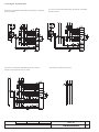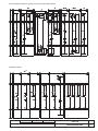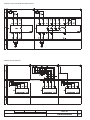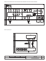
1
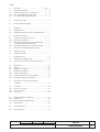
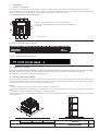
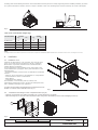
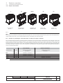
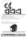
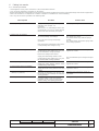
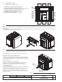
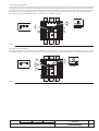
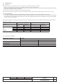
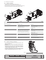
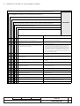
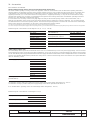
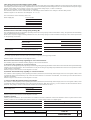
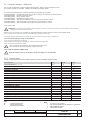
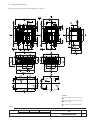
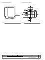
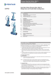
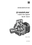
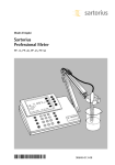
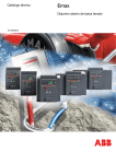
IInstallation and service
instructions
Installation, service and maintenance instructions
for low voltage moulded case circuit-breakers
1SDH000682R0002
Tmax T8
L3692
Dwg.
Resp. Off. LB-DTAT
Take over Off.
App.
Model
L3692
Title
Installation, service and maintenance
instructions for low voltage moulded
case circuit-breakers
Apparatus
ABB SACE Division
Doc.No.
Tmax T8
1SDH000682R0002
Language
en
Scale
Index
1.
Description ................................................................ pag.
3
1.1
General characteristics................................................... «
3
1.2
1.3.1
External front view of the circuit-breaker ....................... «
IEC Circuit-breaker rating plate data ............................ «
3
3
1.3.2
UL Circuit-breaker rating plate data ............................. «
3
2.
Checking on receipt ....................................................... «
3
3.
Storage, lifting and weights ........................................... «
3
4.
Installation ....................................................................... «
4
4.1
4.2
Installation room .............................................................. «
Installation of the flange on the compartment door ....... «
4
4
5.
Electrical connections ..................................................... «
5
5.1
Connections to the power circuit ................................... «
5
5.1.1
Shapes of the terminals .................................................. «
5
5.1.2
5.1.3
Examples of positioning the connection busbars
according to the types of terminals ............................. «
Assembly procedure for the connection busbars ........ «
5
6
5.2
Wiring the circuit-breaker auxiliary circuits .................... «
6
6.
Putting into service ......................................................... «
7
6.1
General procedures ....................................................... «
7
7.
Instructions for use ......................................................... «
8
7.1
Operating and signalling parts ...................................... «
8
7.2
Circuit-breaker closing and opening procedures ........ «
8
8.
Maintenance ................................................................... « 10
8.1
Warning .......................................................................... « 10
8.2
Maintenance program .................................................... « 10
8.3
Maintenance operations ................................................. « 11
8.3.1
Preliminary operations .................................................... « 11
8.3.2
8.3.3
General inspection of the circuit-breaker ...................... « 11
Operating mechanism maintenance ............................. « 11
9.
Measures to be taken for any operating
anomalies ...................................................................... « 12
10.
Accessories ..................................................................... « 13
10.1
10.2
10.3
Electrical accessories .................................................... « 13
Mechanical locks ........................................................... « 15
Spare parts .................................................................... « 15
11.
Protection releases - References ................................... « 16
11.1 Safety notes .................................................................... « 16
11.1.1 Notes for dielectric stiffness tests ................................... « 16
11.2
General notes.................................................................. « 16
12.
Overall dimensions ......................................................... « 17
13.
Circuit diagrams ............................................................. « 23
Model
L3692
Apparatus
Doc. No.
Tmax T8
1SDH000682R0002
Scale
Page No.
1/29
Model
L3692
Apparatus
Doc.No.
Tmax T8
1SDH000682R0002
Scale
Page No.
2/29
1.
Description
1.1
General characteristics
Tmax T8 serie of circuit-breakers and disconnectors consist of a plastic structure which houses the operating mechanism, the poles
and the auxiliary parts. Each pole, insulated from the others, contains the circuit-breaking parts and the current sensor of the corresponding
phase. The fixed version circuit-breaker has its own terminals for connection to the power circuit.
1.2
External front view of the circuit-breaker
1 PR232/P-T8, PR331 o PR332 electronic microprocessor-based release
2 Operating and control parts of the operating mechanism and release tripped signals
3 Rating plate
1
3
2
Fixed circuit-breaker
Fig. 1
1.3.1 IEC Circuit-breaker rating plate data
Fig. 2
1.3.2 UL Circuit-breaker rating plate data
Fig. 3
2.
Checking on receipt
Examine the state of the material received and its consistency with the content of the order. Should any damage or errors be found on unpacking,
which must be carried out carefully, make the relative notification within and not over 5 days from the receipt of the material.
The notification must indicate the number of the shipping note.
3.
Storage, lifting and weights
The circuit-breaker, protected by an external wooden crate, is fixed by means of screws to the transport pallet or to the bottom of the packing
case. If the circuit-breaker has to remain in the warehouse even for a short time before being put into service, after checking it on receipt,
it must be put back in its container and covered with a waterproof sheet.
Caution
– Use a dry, dust-free room free of aggressive chemical agents as a storage room
– Position the circuit-breaker and any fixed part on a horizontal surface, not in direct contact with the floor, but on a suitable support surface
(Fig. 4)
– The maximum number of stackable circuit-breakers is indicated in figure 5
– Keep the circuit-breaker in the open position and with the closing springs discharged to avoid unnecessary stresses and the risk of accidents
to the personnel.
Fig. 4
Model
Fig. 5
L3692
Apparatus
Doc. No.
Tmax T8
1SDH000682R0002
Scale
Page No.
3/29
For lifting, refer to the following instructions: the circuit-breakers must be placed on a sturdy supporting surface and lifted, preferably, by means
of a special fork-lift truck. However, the use of ropes is allowed. In this case, the lifting ropes must be hooked up as shown in the figures
Fig. 6
Table of the circuit-breaker weights (Kg.)
Circuit-breaker
3 poles
Kg
Lbs
Kg
4 poles
Lbs
T8 1600 (UL)
73
161
95
209
T8 2000
73
161
95
209
T8 2500
73
161
95
209
T8 3000 (UL)
107
236
140
308
T8 3200 (IEC)
107
236
140
308
Notes
The weights indicated in the table are intended for circuit-breakers complete with PR232/P-T8, PR331 or PR332 releases and relative current sensors, excluding the accessories.
4.
Installation
4.1
Installation room
Install the circuit-breaker in a dry, dust-free, non-corrosive room,
and in such a way that it is not subject to shocks or vibrations.
Where this is not possible, install it inside a switchboard with a
suitable degree of protection.
For the preparation of the installation room, please refer to the
“Overall dimensions” paragraph, which gives information on the
following points:
– minimum installation volumes of the circuit-breakers and derived
versions
– distances to be respected for circuit-breakers in compartments
– overall dimensions of the circuit-breakers
– fixing drillings
– compartment door drillings.
The installation, commissioning and any ordinary and
extraordinary maintenance have to be done by skilled personnel,
with a detailed knowledge of the apparatus.
To install a circuit-breaker in the switchboard is enough to fix the circuitbreaker to a vertical surface with M8 screws (fig. 7).
4.2
Fig.7
Installation of the flange on the compartment door (Fig. 8)
– Make the compartment door drillings specified in the “Overall dimensions” paragraph.
– Attach the flange (1) on the front of the compartment door, fixing it from the inside by means of the self-tapping screws (2).
2
1
Fig. 8
Model
L3692
Apparatus
Doc.No.
Tmax T8
1SDH000682R0002
Scale
Page No.
4/29
5.
Electrical connections
5.1
Connections to the power circuit
5.1.1
Shapes of the terminals
F
VR/HR
ES
Front terminals
extended (IEC)
Front terminals
(IEC/UL)
VR
Adjustable rear
terminals (IEC)
VR
Vertical rear
terminals (IEC)
Vertical rear
terminals (UL)
Fig. 9
Note
The drawings are provided to show the type of terminal in graphic form. The exact shape of the terminals is given in the “Overall dimensions”
chapter. Different terminals can be installed between the top and bottom parts (inlet and outlet).
5.1.2
Examples of positioning the connection busbars according to the types of terminals
The connection busbars enable the connection between the terminals of the circuit-breakers and the busbars of the switchgear. Their sizing
must be carefully studied by the switchgear designer. Some examples of possible constructions in relation to the shape and size of the circuitbreaker terminals are given in this paragraph. It is normally advisable to exploit the whole contact surface of the terminal, so the width of the
connection busbars should be the same as that of the terminal. Different connection capacities can be obtained by adjusting the thickness
and number of busbars in parallel. In some cases, reductions in the width of the connection in relation to that of the terminal are allowable as
shown in the following examples.
Front terminals
Circuit-breaker
Iu [A]
Vertical rear terminals
Busbar cross-section
Busbar cross-section
[mm2]/[in2]
T8
T8
T8
T8
T8
V
L-V
L-V
V
L-V
1600
2000
2500
3000
3200
[mm2]/[in2]
3x(100x5) / 3x(3.94x0.2)
3x(100x5) / 3x(3.94x0.2)
4x(100x5) / 4x(3.94x0.2)
-
6x(100x5) / 6x(3.94x0.2)
6x(100x5) / 6x(3.94x0.2)
Fig. 10
Model
L3692
Apparatus
Doc. No.
Tmax T8
1SDH000682R0002
Scale
Page No.
5/29
Positioning the first anchoring baffle of the busbars
Anchoring to the switchgear
190
7.48"
190
7.48"
190
7.48"
190
7.48"
190
7.48"
190
7.48"
190
7.48"
Fig. 11
5.1.3 Assembly procedure for the connection busbars
Check the state of the contact surfaces of the connections very carefully: they must be very clean with no burrs, dents or traces of rust which
must be eliminated using a fine file or an emery cloth to prevent localized increases in temperature. On completion of the operation, remove
all traces of grease or dust with a cloth soaked in a suitable solvent.
When aluminium connections are used, it is necessary to tin-plate the contact surfaces.
The connections must not exert any strain on the terminals in any direction.
Always insert a large-diameter flat washer and a spring washer between them (to spread the tightening pressure over a greater area).
Make the contact between connection and terminal and tighten the fixing screws completely.
Always use two wrenches (so as not to strain the insulating parts excessively), applying the tightening torque
of the main terminals =70 Nm/615 lb in for M12 high strength screws. Check tightness after 24 hours.
5.2
Wiring the circuit-breaker auxiliary circuits
A special terminal box is provided, fitted with screw terminals for connecting the auxiliary circuits.
The terminals are marked with alphanumerical identification codes as for the electrical circuit diagram.
The terminal box is identified by code XV on the electrical circuit diagram.
The terminal box is immediately accessible when the compartment door is open.
XV
Fig. 12
Model
L3692
Apparatus
Doc.No.
Tmax T8
1SDH000682R0002
Scale
Page No.
6/29
6.
Putting into service
6.1
General procedures
– Check tightness of the power connections at the circuit-breaker terminals
– Carry out all the preparatory operations on the release
– Make sure that the value of the auxiliary circuit power supply voltage is between 85 and 110% of the rated voltage of the electrical applications
– Make sure that there is an adequate air circulation in the place of installation to avoid overheating
– Also carry out the checks specified in the following table.
Item inspected
Procedure
Positive check
1 Manual operating mechanism
Carry out some opening and closing
operations (see chapter 7.2).
CAUTION
When there is an undervoltage release, the
circuit-breaker can only be closed after the
release has been electrically energized.
The spring loading lever moves correctly.
2 Geared motor (if provided)
Supply the spring loading geared motor at
the corresponding rated voltage.
The springs are loaded correctly.
The signals are correct.
The geared motor stops with the springs
loaded.
The geared motor reloads the springs after
each closing operation.
Carry out some closing and opening
operations.
Note. Supply the undervoltage release at the
corresponding rated voltage (if any).
3 Undervoltage release (if provided)
Supply the undervoltage release at the
corresponding rated voltage and carry out
the circuit-breaker closing operation.
Disconnect voltage to the release.
The circuit-breaker closes correctly. The
signals are correct.
Supply the undervoltage release at the
corresponding rated voltage and carry out
the circuit-breaker closing operation.
The circuit-breaker opens. The signal changes
over.
4 Shunt opening release (if provided)
Close the circuit-breaker.
Supply the shunt opening release at the
corresponding rated voltage.
The circuit-breaker opens correctly. The
signals are correct.
5 Shunt closing release (if provided)
Open the circuit-breaker.
Supply the shunt closing release at its rated
voltage.
The circuit-breaker closes correctly. The
signalsare correct.
6 Circuit-breaker lock in the open position
(with key or padlocks)
Open the circuit-breaker, turn the key and
remove it from its seat. Attempt circuit-breaker
closing operation.
Both manual and electrical closing are
prevented.
7 Auxiliary contacts of the circuit-breaker
Insert the auxiliary contacts in suitable
signalling circuits. Carry out some circuitbreaker closing and opening operations.
The signals are given correctly.
Model
L3692
Apparatus
Doc. No.
Tmax T8
1SDH000682R0002
Scale
Page No.
7/29
7.
Instructions for use
7.1
Operating and signalling parts
1
2
3
4
5
6
7
8
Pushbutton for the manual opening operation
Lever for manual loading of the closing springs
Mechanical indicator for circuit-breaker open “O” and closed “I”
Mechanical indicator for protection release tripped
Pushbutton for the manual closing operation
Signalling device for springs loaded - unloaded
Operation counter (on request)
Key lock on the closing operation (on request)
4
8
5
1
6
2
3
7
Fig.13
Note
On request, a transparent cover can be installed on the front of the circuit-breaker to increase the degree of protection to IP54. The cover has
a locking key.
As an alternative to the transparent cover, a protection can be mounted on the manual closing and opening controls, which only allows operation
of the pushbuttons by means of a special tool.
Fig. 14
7.2
Circuit-breaker closing and opening procedures
The operation of the circuit-breaker can be either manual or electrical.
a) Manual loading of the closing springs
– Make sure that the indicator (3) shows “O” (circuit-breaker open)
– Make sure that the indicator (6) is WHITE (springs discharged)
– Repeatedly activate the lever (2) until the indicator (6) changes its
color to YELLOW
b) Electrical loading of the closing springs
The electrical loading of the circuit-breaker is possible when the
following accessories (supplied on request) are present:
– geared motor for automatic loading of the closing springs
– shunt closing release
– shunt opening release.
The geared motor automatically reloads the springs after each closing
operation until the yellow indicator appears (6, Fig. 15). When the
power is cut off during loading, the geared motor stops and
automatically starts reloading the springs again when the power
returns. It is, in any case, always possible to complete the reloading
operation manually.
Model
L3692
2
3
6
Fig. 15
Apparatus
Doc.No.
Tmax T8
1SDH000682R0002
Scale
Page No.
8/29
c) Closing the circuit-breaker
The operation can only be carried out with the closing springs fully loaded. For manual closing, press the pushbutton (5) marked with the letter
“I”. When there is a shunt closing release, the operation can be carried out remotely by means of the special control circuit. The special indicator
(3) changes to indicate “I” to signal that the circuit-breaker has closed. Furthermore, the indicator of the state of the springs (6) goes to the
WHITE position. Even with the closing springs discharged, the operating mechanism retains enough energy for the opening operation.
The geared motor,if any, immediately starts the automatic spring reloading operation.
5
3
Premere
6
Fig. 16
d) Opening the circuit-breaker
For manual opening of the circuit-breaker, press pushbutton “O” (1). When there is a shunt opening release, the operation can also be carried
out remotely by means of the special control circuit. Opening having taken place is signaled by the letter “O” appearing in the indicator (3).
1
Premere
3
Fig. 17
Model
L3692
Apparatus
Doc. No.
Tmax T8
1SDH000682R0002
Scale
Page No.
9/29
8.
Maintenance
8.1
Warning
Before carrying out any maintenance work, it is necessary to complete the following procedure:
– open the circuit-breaker and check that the operating mechanism springs are discharged
– for action on circuit-breakers disconnect the supply to the power circuit and to the auxiliary circuits; furthermore, visibly earth the terminals both
on the power supply side and on the load side.
During normal service, the circuit-breakers require limited maintenance.
The table of the maintenance program is given in the following paragraph, indicating the corresponding periodic intervals for action.
It is also recommended:
– During service, routinely inspect the circuit-breaker from the outside to check for any dust, dirt or damage of any kind.
– For circuit-breakers fitted with SACE PR232/P-T8 and PR331 releases,installation of the mechanical operation counter (supplied on request)is
recommended; the SACE PR332 releases allow for the number of operations performed by the circuit-breaker in service to be displayed
at all times on the special display.
With regular maintenance, Tmax T8 circuit-breakers, either with or without a geared motor, can withstand the following operation without
replacement of parts.
Rated uninterrupted current
Mechanical life (*)
Iu (40 °C)
[A]
No. of operations Frequency
415 V ~
Frequency
x 1000
operations/hour No. of operations x 1000 operations/hour
T8 (UL)
T8
T8
T8 (UL)
T8 (IEC)
1600
2000
2500
3000
3200
15
15
15
15
15
60
60
60
60
60
Electrical life
4,5
4,5
4
3
3
20
20
20
20
20
(*) With regular ordinary maintenance
8.2
Maintenance program
Maintenance operations
Interval
Installation in normal rooms
Installations in dusty or polluted rooms
General inspection (see par. 8.3.2)
External visual check and inspection
of the power section
Operating mechanism maintenance (par. 8.3.3)
One year or after a short-circuit trip
One year
Six months or after a short-circuit trip
Six months
One year or 5000 operations
Six months or 3000 operations
Checking trip of the release
One year
Six months
Model
L3692
Apparatus
Doc.No.
Tmax T8
1SDH000682R0002
Scale
Page No.
10/29
8.3
Maintenance operations
8.3.1 Preliminary operations
– Put the CB in safe-mode like described at par. 8.1
– Uplift the flange (1) of the release, as shown in the figures
– Remove the front escutcheon plate (2) by removing the four screws (3)
– Remove both side guards (4) by removing the front (5) screws
4
4
5
5
1
1
3
3
2
8.3.2
2
T8 III
Fig. 18
T8 IV
General inspection of the circuit-breaker
Item to be inspected
Problem found
Remedy
1 Operating mechanism/Electrical accessories
– Presence of dust on the internal parts
– Springs deformed or rusty
– Safety rings out of place, nuts or screws loose
– Wires and straps detached
– Clean with brushes or dry cloths
– Replace damaged springs
– Put the rings back in place and tighten screws and
nuts appropriately
– Replace the straps and connect the detached wires
correctly
2 Main circuit - Busbars
– Presence of dust or dirt on the insulating parts
– Safety rings out of place, screws or nuts loose
– Deformation or cracks of the insulating parts
– Wear or overheating marks or screws loose on the
connections to the terminals of the circuit-breaker
– Clean with a brush or dry cloths
– Put the rings back in place and tighten screws and
nuts appropriately
– Remove the shutters and clean with a rough cloth
soaked in a suitable solvent and lubricate moderately
with neutral grease
– Tighten the screws suitably
3 Auxiliary circuit power supply voltage
Check the power supply voltage of the electrical
accessories of the operating mechanism
The releases and locking devices must operate
normally for values between 85% and 110% of the
corresponding rated voltage
4 Operating and control parts
The operating tests, which must be carried out as
shown in paragraph 6.1 have shown defects in the
components
Replace the defective parts or those with a faulty
operation (if necessary, ask ABB)
8.3.3
Operating mechanism maintenance
– Carry out the checks and take the action listed under item 1 of the
table in paragraph 8.3.2.
– Achieve 10 opening, closing and relay tripped operations through
the release.
– Lubricate the bearings of the drive shaft with MU-EP1 (AGIP) grease,
including those on the sides of the circuit-breaker. Equivalent
greases:ESSO Beacon EP1 - BP LTX1 - SHELL AVANIA GREASE R1
- KLUBER LUBRIFICATION CENTO PLEX 2P
– Lubricate the small opening and closing shafts and the hooks with
5 RX MOLY (OLEOTECNICA) grease (Fig. 19);equivalent grease:
KLUBER LUBRIFICATION GRAFLOSCON A-G 1 ULTRA.
Fig. 19
Model
L3692
Apparatus
Doc. No.
Tmax T8
1SDH000682R0002
Scale
Page No.
11/29
9.
Measures to be taken for any operating anomalies
Pressing the i-Test pushbutton on the PR332 does not cause circuit-breaker opening
The WARNING or ALARM led on the PR332 release lights up
Release coils interrupted or burnt out, geared motor winding interrupted
The shunt opening release or shunt closing release does not energize sufficiently
Anomalies
The shunt opening release or shunt closing release remains energized
The circuit-breaker does not close
The circuit-breaker does not open
Possible causes
•
•
•
•
•
•
• • ••
• ••
•• •
• ••
•• •
••
• ••
•
•
•
Model
L3692
Checks and remedies
Connector XO not inserted correctly
Check and insert connector XO correctly
Coil of the opening release YO1 interrupted
Replace the YO1 shunt opening release
Defect in the electronic circuits of the microprocessor
release
Put the circuit-breaker out of service and check the release
with the test apparatus
The possible causes of tripping are listed in the part of the
manual relating to the releases
Take action according to the cause: in particular, if contact
wear is higher than 80% (WARNING led lit up), the circuitbreaker can remain in service, but replacement of the circuitbreaking partsmust be scheduled within a short time. If contact
wear reaches 100%, the circuit-breaker must be put out of
service immediately. Ask ABB about replacement procedures
for the circuitbreaking parts
Protections not reset
Press the mechanical pushbutton for signalling protection
tripping
Operating mechanism or consent contacts blocked in
closing position
Check the state of the contacts in series with the release circuit
Auxiliary circuit power supply voltage too low
Measure the voltage: it must not be less than 85% of the rated
voltage
Different power supply voltage from the one indicated on the
rating plate of the releases
Check the rating plate voltage of the releases
Operating circuit faulty
Check connections, fuses, interlocks, protection circuit-breakers
and consent contacts
Wire tightening screws loose
Check tightness of the screws connecting the wires
Incorrect electrical connections in the power supply circuit
Check the connections with the corresponding circuit diagram
Release coils interrupted
Replace the coils
Operating mechanism blocked
Operate by hand. If the fault persists contact ABB
Key not inserted in the opening mechanism lock
Insert and turn the key
Undervoltage release not energized
Check the corresponding power supply circuit
Shunt opening release remains energized
Check the power supply circuit
Apparatus
Doc.No.
Tmax T8
1SDH000682R0002
Scale
Page No.
12/29
10. Accessories
10.1 Electrical accessories
Shunt opening/closing (YO/YC) and second shunt opening release (Y02
This allows remote opening or closing control of the apparatus. Given the characteristics of the circuit-breaker operating mechanism,
opening (with the circuit-breaker closed) is always possible, whereas closing is only possible when the closing springs are loaded. Most
of the releases can operate with either direct or alternating current. This release carries out an instantaneous service (*), but can be
supplied permanently (**). In uses where the shunt closing release is supplied permanently, to carry out the circuit-breaker reclosing
operation after opening, it is necessary to momentarily de-energize the shunt closing release (the circuit-breaker operating mechanism
reclosing is, in fact, fitted with an antipumping device).
In some versions it is necessary to have a very high degree of safety for the remote opening control of the circuit-breaker, and, in
particular, the duplication of the control circuit of the shunt opening release is required. In order to achieve this, you can fit the Tmax T8
circuit-breakers with a second shunt opening release. The second shunt opening release is located in the same seat as the undervoltage
release and its technical characteristics are the same as the standard shunt opening release.
(*) In the case of instantaneous service, the minimum duration of the current impulse must be 100 ms.
(**) In the case of permanent power supply to the shunt opening release, you must wait for at least 30 ms before giving the opening control to the shunt closing release.
Reference figures in the electrical circuit diagrams: YO (4) - YC (2) - YO2 (8)
Power supply (Un)
24 V DC
30 V AC/DC
48 V AC/DC
60 V AC/DC
110-120 V AC/DC
120-127 V AC/DC
220-240 V AC/DC
240-250 V AC/DC
380-400 V AC
Operating limits
(CEI EN 60947-2)
Inrush power consumption (Ps)
Inrush power time ~100 ms
Continuous power (Pc)
Opening time (YO - YO2)
Closing time (YC)
Insulation voltage
(YO-YO2) : 70…110% Un
(YC) : 85…110% Un
DC = 200 W
AC = 200 VA
DC = 5 W
AC = 5 VA
(max) 60 ms
(max) 80 ms
2500V 50 Hz (for 1 min.)
440 V AC
Undervoltage release (YU)
The undervoltage release opens the circuit-breaker in the case of a considerable drop or lack of its power supply voltage. It can be used for
remote tripping (by means of normally closed type pushbuttons), as a lock on closing or to control the voltage in the primary and secondary
circuits. The release power supply is therefore branched on the supply side of the circuit-breaker or from an independent source. Circuit-breaker
closing is only allowed with the release powered (the closing lock is carried out mechanically). Most of the releases can operate with either
direct or alternating current.
Power supply (Un)
24 V DC
30 V AC/DC
48 V AC/DC
60 V AC/DC
110-120 V AC/DC
120-127 V AC/DC
220-240 V AC/DC
240-250 V AC/DC
380-400 V AC
440 V AC
Operating limits:
(CEI EN 60947-2).
(YO-YO2): 70% ... 110% Un
(YC): 85% ... 110% Un
Circuit-breaker opening takes place with power supply voltage values of the release equivalent to 35 - 70% Un.
Circuit-breaker closing is possible with power supply voltage of the release equivalent to 85-110% Un.
It can be fitted with a signalling contact for undervoltage release energized (C. aux YU).
Reference figures in the electrical circuit diagrams: YU (6)
Inrush power consumption (Ps):
DC = 200 W
AC = 200 VA
Continuous power (Pc):
DC = 5 W
AC = 5 VA
Openig time (YU):
30 ms
Insulation voltage
2500V 50 Hz (for 1 min.)
Model
L3692
Apparatus
Doc. No.
Tmax T8
1SDH000682R0002
Scale
Page No.
13/29
Time delay device for undervoltage release (UVD)
The undervoltage release can be combined with an electronic time-delay device for installing outside the circuit-breaker, which enables a delay
in the tripping of the release with preset, adjustable times. The use of the delayed undervoltage release is recommended when the power supply
network of the release can be subject to power cuts or short-lived voltage drops, in order to avoid trips.
When it is not supplied, circuit-breaker closing is prevented.
The time-delay device has to be combined with an undervoltage release with the same voltage as the time-delay device.
Reference figures in the electrical circuit diagrams: YU + D; (7).
The characteristics of the time-delay device are:
Power supply (D):
24-30 V AC/DC
48 V AC/DC
60 V AC/DC
110-127 V AC/DC
220-250 V AC/DC
Adjustable opening time (YU+UVD): 0,5-1-1,5-2-3 s
Geared motor for automatic closing spring loading (M)
This automatically loads the circuit-breaker operating mechanism closing springs. After circuit-breaker closing, the geared motor immediately
sees to reloading the closing springs.
When there is no power supply or during maintenance work, the closing springs can still be loaded manually (by means of the special lever
on the operating mechanism).
Power supply (Un)
24-30 V AC/DC
Inrush power consumption (Ps): DC = 500W
AC = 500 VA
48-60 V AC/DC
100-130 V AC/DC
220-250 V AC/DC
Operating limits:
85…110% Un (CEI EN 60947-2)
Insulation voltage:
2500 V 50 Hz (for 1 min.)
Rated power (Pn):
DC = 200 W
AC = 200 VA
Inrush time
0,2 s
Loading time:
4-5 s
It is always supplied with limit contacts and microswitch for signalling closing springs loaded.
Reference figure in the electrical circuit diagrams: M (1)
Mechanical and electrical trip signalling for overcurrent releases
The following signals are available following tripping of the overcurrent release:
a) Mechanical trip signalling for overcurrent releases
This enables a visual signalling on the operating mechanism by pushing the trip pushbutton in when the circuit-breaker has been opened following
tripping of an overcurrent release. The circuit-breaker can only be closed again by putting the pushbutton back into its normal position included
in the standard configuration.
Reference figure in the electrical circuit diagrams: S51 (13).
b) Electrical and mechanical trip signalling for overcurrent releases
This enables a visual signalling on the operating mechanism (mechanical) and remotely (electrically by means of a changeover switch) of the
circuitbreaker being opened following a trip of the overcurrent releases. To reset the circuit-breaker, it is necessary to reset the mechanical
indicator pushbutton.
Reference figure in the electrical circuit diagrams: S51 (13).
c) Coil for resetting the mechanical release trip indicator
This enables a visual signalling on the operating mechanism (mechanical) and remotely (electrically by means of a changeover switch) of the
circuitbreaker being opened following a trip of the overcurrent releases. With this accessory, you can reset the mechanical indicator with an
electronic relay using a remote control and this enables the circuit-breaker to be reset.
Power supply (Un)
24-30 V AC/DC
220-240 V AC/DC
110-130 V AC/DC
Reference figure in the electrical circuit diagrams: S51 (14)
Auxiliary contacts
Auxiliary contacts installed on the circuit-breaker are available to enable an indication of the circuit-breaker’s status. A special version of the
auxiliary contacts is also available (gold plated contacts) for a rated voltage under 24 V (digital signal).
Un
In max
T
Un
In max
cosϕ
ϕ
125 V DC
0,3 A
10 ms
250 V AC
5A
0,3
250 V DC
0,15 A
10 ms
400 V AC
2A
0,3
Model
L3692
Apparatus
Doc.No.
Tmax T8
1SDH000682R0002
Scale
Page No.
14/29
The versions available are:
a) Electrical signalling for circuit-breaker open/closed
It is possible to have electrical signalling of the circuit-breaker status (open/closed) with 4 auxiliary contacts.
The auxiliary contacts can have the following configurations:
– 4 break/make contacts for PR232-PR331 (4 Change-over position contact)
– 4+1 break/make contacts for PR332 (4 Change-over position contact + 1 for the release)
Reference Fig. in the electrical circuit diagrams: Q/1÷10 (21-22)
b) Contact for signalling closing springs charged
This consists of a microswitch which allows remote signalling of the state of the circuit-breaker operating mechanism closing springs. The contact
is always supplied with the spring loading geared motor.
Reference figure in the electrical circuit diagrams: S33 M/2 - (11)
c) Contact for signalling undervoltage release energized (C.aux YU)
The undervoltage releases can be fitted with a contact (by choise, normally closed or open) for signalling undervoltage energized for remote
signalling of the state of the undervoltage release.
Reference figure in the electrical circuit diagrams: (12)
Sensors and operations counter
a) Current sensor for the neutral conductor outside the circuit-breaker
The sensor allows neutral protection by means of connection to the overcurrent release and is available only for three-pole circuit-breakers.
It is supplied on request.
Reference figure in the electrical circuit diagrams: UI/N
b) Homopolar toroid for the power supply earthing conductor (star center of the transformer)
PR232/P-T8 microprocessor-based electronic release may be used in combination with an external toroid located on the conductor, which
connects the star center of the MV/LV transformer (homopolar transformer) to earth: in this case, the earth protection is defined as Source Ground
Return.
The In of the toroid can be regulated to 100 A, 250 A, 400 A, 800 A by using different combinations of the connections.
Reference figure in the electrical circuit diagrams: UI/0.
c) Homopolar toroid for residual current protection
The toroid enables the residual current protection to be activated and can be combined with the PR332/P LSIRc release.
The accessory is fittedwith a dip-switch multiple selector which is reset according to the required sensitivity (3A to 30A).
The accessory is for installation on the busbars and is available in different sizes,up to 3200A.
d) Mechanical operations counter
This is connected to the operating mechanism by means of a simple lever mechanism. It indicates the number of circuit-breaker mechanical
operations. The indication is visible on the front of the circuit-breaker from the outside.
10.2 Mechanical locks
a-b) Lock in open position
Different mechanisms are available which enable the circuit-breaker to be locked in the open position.
These devices can be controlled by:
– a key (a): a special circular lock with different keys (for a single circuit-breaker) or with the same keys (for several circuit-breakers). In the
latter case, up to four different key code numbers are available.
– padlocks (b): up to 3 padlocks (not supplied): Ø 4 mm.
Transparent protection covers
a) Protection covers for opening and closing pushbuttons
These protection covers, applied over the opening and closing pushbuttons, prevent the corresponding circuit-breaker operations except
by using a special tool.
b) IP54 door protection
This is provided by means of a transparent plastic escutcheon plate which fully protects the front of the circuit-breaker and ensures a degree
of protection to IP54. Mounted on hinges, it is fitted with a key lock.
10.3 Spare parts
The spare parts available are:
– Shields and front escutcheon plate
– Closing springs
– Complete pole
– Operating mechanism
– SACE PR030/B power supply unit
For further details, ask for the ABB spare parts catalogue.
Model
L3692
Apparatus
Doc. No.
Tmax T8
1SDH000682R0002
Scale
Page No.
15/29
11. Protection releases - References
The Tmax T8 circuit-breaker could be equipped with the PR232 - PR331 - PR332 protection releases.
The following modules are available : PR330/V-T8, PR330/D-M, PR330/R, BT030.
For further detailed informations on releases operating see following documentation:
1SDH000587R0001 Operating istructions for T7-T8-X1 low voltage circuit breakers protection releases
1SDH000591R0001 PR232/P-T8 Getting started
1SDH000592R0001 PR331 Getting started
1SDH000593R0001 PR332/PR333 Getting started
1SDH000650R0501 ABB SACE PR232/P-T8 microprocessor-based electronic release
1SDH000650R0502 ABB SACE PR331 T8 microprocessor-based electronic release
1SDH000650R0503 ABB SACE PR332 T8 microprocessor-based electronic release
11.1 Safety notes
WARNING: this symbol gives information about operations, actions or circumstances that can cause injuries to the personnel,
damage to the unit or economic losses
Read this manual carefully and completely, the specifically protection release instruction manual and the getting started.
The use of this device should be reserved for qualified and expert personnel only.
If in doubt, about its safe usage, the unit must be put out of service to prevent any accidental use.
You must assume that safe usage is impossible if:
1. the unit shows visible signs of damage.
2. the unit does not function (for example with autotest or with the trip test unit).
3. the unit has been damaged in transit.
Prior to servicing and/or replacing, the circuit-breaker must be open.
Also remember to disconnect all power supplies connected.
11.1.1 Notes for dielectric stiffness tests
Dielectric stiffness tests on the releases, inputs and outputs, are not permitted.
11. 2 General notes
A table can best illustrate the technical features and the mix and matchability of the three relays.
Function/Unit
PR232
PR331
Current protections (L, S, I, G)
S
S
S
Additional protections (U, OT)
-
-
S
Voltage protections (UV, OV, RV, RP, UF, OF)
-
-
S(4)
(1)
PR332
Temperature protection
-
-
S
MCR protection
-
-
S
Thermal memory
S
S
S
Local bus for separate auxiliary units
-
S
S
Wire communication (RS485)
-
Radio communication (wireless Bluetooth)
Data Logger
S
-
(2)
S
-
S (3)
(2)
S (2)
S
Compatibility with SD-Pocket
S
S
S
Compatibility with SD-Testbus
S
S
S
Compatibility with PR010/T
S
S
S
PR330/V Measuring (internal voltage module)
-
-
O
PR330/D-M Com (internal communication module)
-
-
O
Residual current protection
-
-
O
PR021/K (separate signalling unit)
-
O
O
HMI030 (separate graphics interface)
-
O
O
PR030/B (separate power supply unit)
BT030 (separate Bluetooth communication unit)
O
O
O
O
S
O
Key:
S
O
-
Model
: standard function/unit,
: optional function/unit,
: function/unit unavailable
L3692
Note:
1.
2.
3.
4.
: G function is not available,
: with separate BT030 unit (for temporary connections),
: with PR330/D-M module,
: with PR330/V module.
Apparatus
Doc.No.
Tmax T8
1SDH000682R0002
Scale
Page No.
16/29
12. Overall dimensions
Basic version with front terminals 1600A/2000A/2500A - F (IEC/UL)
3
1
N
N
2
2
Legend
1 Inside edge of compartment door
2 Circuit-breaker M8 fixing drilling
(use M8 screws)
3 Insulating or metal-insulated wall
Fig. 20
Model
L3692
Apparatus
Doc. No.
T8
1SDH000682R0002
Scale
Pag. No.
17/29
Basic version with front terminals extended 2000A/2500 - ES (IEC)
3
1
N
N
2
2
Legend
1 Inside edge of compartment door
2 Circuit-breaker M8 fixing drilling
(use M8 screws)
3 Insulating or metal-insulated wall
Fig. 21
Model
L3692
Apparatus
Doc. No.
T8
1SDH000682R0002
Scale
Pag. No.
18/29
Basic version with adjustable rear terminals 2000A/2500A - HR/VR (IEC)
3
1
N
N
2
2
Legend
1 Inside edge of compartment door
2 Circuit-breaker M8 fixing drilling
(use M8 screws)
3 Insulating or metal-insulated wall
Fig. 22
Model
L3692
Apparatus
Doc. No.
T8
1SDH000682R0002
Scale
Pag. No.
19/29
Basic version with vertical rear terminals 3200A - VR (IEC)
3
1
N
N
2
2
Legend
1 Inside edge of compartment door
2 Circuit-breaker M8 fixing drilling
(use M8 screws)
3 Insulating or metal-insulated wall
Fig. 23
Model
L3692
Apparatus
Doc. No.
T8
1SDH000682R0002
Scale
Pag. No.
20/29
Basic version with vertical rear terminals 3000A - VR (UL)
3
1
N
N
2
2
Legend
1 Inside edge of compartment door
2 Circuit-breaker M8 fixing drilling
(use M8 screws)
3 Insulating or metal-insulated wall
Fig. 24
Model
L3692
Apparatus
Doc. No.
T8
1SDH000682R0002
Scale
Pag. No.
21/29
Compartment dimensions
Compartment door drilling
Depth
3 POLES
4 POLES
Fig.25
Model
Fig.26
L3692
Apparatus
Doc. No.
T8
1SDH000682R0002
Scale
Pag. No.
22/29
13. Circuit diagrams
Warning
Before installing the circuit-breaker, carefully read notes F and O on the circuit diagrams.
Operating status shown
The circuit diagram is for the following conditions:
- circuit breaker open
- circuits de-energised
- releases not tripped
- motor operating mechanism with springs unloaded.
Versions
Version without overcurrent release
With this version, the applications indicated in figures 13, 14, 41, 42, 43, 44, 45, 46, 62 cannot be provided.
Version with PR232/P-T8 electronic release
With this version, the applications indicated in figures 41, 42, 43, 44, 45, 46, 62 cannot be provided.
Version with PR331/P electronic release
With this version, the applications indicated in figures 42, 43, 44, 45, 46 cannot be provided.
Version with PR332/P electronic release
With this version, the applications indicated in figure 41 cannot be provided.
Caption
*
A1
A4
A13
AY
D
F1
K51
=
=
=
=
=
=
=
=
=
K51/1...8
K51/GZin(DBin)
K51/GZout(DBout)
K51/SZin(DFin)
K51/SZout(DFout)
K51/YC
=
=
=
=
=
=
K51/YO
=
M
Q
Q/1...5
S33M/1...3
S43
S51
=
=
=
=
=
=
S51/P1
SC
SO
SO1
SO2
SR
SRTC
TI/L1
TI/L2
TI/L3
TO
TU
Vaux.
UI/0
=
=
=
=
=
=
=
=
=
=
=
=
=
=
UI/L1
UI/L2
UI/L3
UI/N
W1
W2
X1...X7
=
=
=
=
=
=
=
Model
Circuit diagram figure number
See note indicated by the letter
Circuit-breaker accessories
Example switchgear and connections for control and signalling, outside the circuit-breaker
PR021/K signalling unit (outside the circuit-breaker)
SACE SOR TEST UNIT Test/monitoring Unit (see note R)
Electronic time-delay device of the undervoltage release, outside the circuit-breaker
Delayed-trip fuse
PR232/P-T8, PR331/P, PR332/P electronic overcurrent release with the following protection functions:
- L overload protection with inverse long time-delay trip-setting I1
- S short-circuit protection with inverse or definite short time-delay trip-setting l2
- I short-circuit protection with instantaneous time-delay trip-setting l3
- G earth fault protection with inverse short time-delay trip-setting l4
Contacts for the PR021/K signalling unit
Zone selectivity: for protection G or “reverse” direction input for protection D (only with Vaux and PR332/P release)
Zone selectivity: for protection G or “reverse” direction output for protection D (only with Vaux and PR333/P release)
Zone selectivity: input for protection S or “direct” input for protection D (only with Vaux and PR332/P release)
Zone selectivity: output for protection S or “direct” output for protection D (only with Vaux and PR332/P release)
Closing control from PR332/P microprocessor-based release with communication module PR330/D-M and with
actuation unit PR330/R
Opening control from PR332/P microprocessor-based release with communication module PR330/D-M and with
actuation unit PR330/R
Motor for loading the closing springs
Circuit-breaker
Circuit-breaker auxiliary contacts
Limit contacts for spring-loading motor
Switch for setting remote/local control
Contact for electrical signalling of circuit-breaker open due to tripping of the overcurrent release. The circuit-breaker may
be closed only after pressing the reset pushbutton, or after energizing the coil for electrical reset (if available)
Programmable contact (for default it signalizes overcurrent protection in progress - start)
Pushbutton or contact for closing the circuit-breaker
Pushbutton or contact for opening the circuit-breaker
Pushbutton or contact for opening the circuit-breaker with delayed trip
Pushbutton or contact for opening the circuit-breaker with instantaneous trip
Pushbutton or contact for electrical circuit-breaker reset
Contact for electrical signalling of circuit breaker open, with springs charged and ready to close
Current transformer located on phase L1
Current transformer located on phase L2
Current transformer located on phase L3
Homopolar toroidal current transformer (see note T)
Isolation voltage transformer (see note O)
Auxiliary power supply voltage (see note F)
Current sensor (Rogowski coil) located on the conductor connecting to earth the star point of the MV/LV transformer
(see note G)
Current sensor (Rogowski coil) located on phase L1
Current sensor (Rogowski coil) located on phase L2
Current sensor (Rogowski coil) located on phase L3
Current sensor (Rogowski coil) located on neutral
Serial interface with control system (external bus): EIA RS485 interface (see note E
Serial interface with the accessories of PR331/P and PR332/P releases (internal bus)
Connectors for the accessories of the circuit-breaker
L3692
Apparatus
Doc. No.
Tmax T8
1SDH000682R0002
Scale
Pag. No.
23/29
XK1
XO
XR3…XR13
XV
YC
YO
YO1
YO2
YR
YU
=
=
=
=
=
=
=
=
=
=
Connector for power circuits of PR232/P-T8, PR331/P and PR332/P releases
Connector for YO1 release
Connectors for auxiliary circuits of PR232/P-T8, PR331/P and PR332/P releases
Delivery terminal box for the auxiliary circuits of the circuit-breaker
Shunt closing release
Shunt opening release
Overcurrent shunt opening release (trip coil)
Second shunt opening release (see note Q)
Coil to electrically reset the circuit-breaker
Undervoltage release (see notes B and Q)
Description of figures
Fig.1
Fig.2
Fig.4
Fig.6
Fig.7
Fig.8
Fig.11
Fig.12
Fig.12A
Fig.13
=
=
=
=
=
=
=
=
=
=
Fig.14
=
Fig.22
Fig.41
Fig.42
Fig.43
=
=
=
=
Fig.44
=
Fig.45
=
Fig.46
=
Fig.61
Fig.62
=
=
Motor circuit to load the closing springs.
Circuit of shunt closing release.
Shunt opening release.
Instantaneous undervoltage release (see notes B and Q).
Undervoltage release with electronic time-delay device, outside the circuit-breaker (see notes B and Q)
Second shunt opening release (see note Q).
Contact for electrical signalling of springs loaded.
Contact for electrical signalling of undervoltage release energized (see notes B and S).
Contact for electrical signalling of circuit breaker open, with springs charged and ready to close
Contact for electrical signalling of circuit-breaker open due to tripping of the overcurrent release. The circuit-breaker may be closed
only after pressing the reset pushbutton, or after energizing the coil for electrical reset (if available).
Contact for electrical signalling of circuit-breaker open due to tripping of the overcurrent release and electrical reset coil. The
circuit-breaker may be closed only after pressing the reset pushbutton or energizing the coil.
Circuit breaker auxiliary contacts.
Auxiliary circuits of PR331/P release (see note F).
Auxiliary circuits of PR332/P release (see note F and N).
Circuits of the measuring module PR330/V-T8 of the PR332/P release internally connected to the three-pole and fourpole
circuit-breaker (optional).
Circuits of the measuring module PR330/V-T8 of the PR332/P release externally connected to the three-pole and fourpole
circuit-breaker (optional)(see note O).
Auxiliary circuits of PR332/P release with communication module PR330/D-M connected to actuation unit PR330/R
(see notes E, F, N and P).
Circuits of the measuring module PR330/V-T8 of the PR332/P release internally connected to the three-poles circuit breaker
with external neutral conductor (optional).
SACE SOR TEST UNIT Test/monitoring Unit (see note R)
Circuits of the signalling unit PR021/K (outside the circuit-breaker).
Incompatibilities
The circuits indicated in the following figures cannot be supplied simultaneously on the same circuit-breaker:
6-7–8
13 - 14
41 - 42 – 45
43 - 44 - 46
Notes
A)
B)
E)
F)
G)
N)
O)
P)
Q)
R)
S)
T)
U)
The circuit-breaker is only fitted with the accessories specified in the ABB SACE order acknowledgement. Consult this catalogue for information
on how to make out an order.
The undervoltage release is supplied for operation using a power supply branched on the supply side of the circuit-breaker or from an
independent source. The circuit-breaker can only close when the release is energized (there is a mechanical lock on closing).
For the EIA RS485 serial interface connection see document RH0298 regarding MODBUS communication.
The auxiliary voltage Vaux allows actuation of all operations of the PR331/P and PR332/P releases.
Having requested a Vaux insulated from earth, one must use “galvanically separated converters” in compliance with IEC 60950 (UL 1950)
or equivalent standards that ensure a common mode current or leakage current (see IEC 478/1, CEI 22/3) not greater than 3.5 mA, IEC
60364-41 and CEI 64-8.
Earth fault protection is available with the PR332/P release by means of a current sensor located on the conductor connecting to earth the star
center of the MV/LV transformer.
The connections between terminals 1 and 2 (or 3) of current transformer UI/O and poles T7 and T8 of the XV connector must be made
with a two-pole shielded and stranded cable (type BELDEN 8762/8772) no more than 15m long. The shield must be earthed on the
circuit-breaker side and current sensor side.
With PR332/P release, the connections to the zone selectivity inputs and outputs must be made with a two-pole shielded and stranded cable
(see type BELDEN 8762/8772), no more than 300 m long.The shield must be earthed on the selectivity input side.
Systems with a rated voltage greater than 690V require the use of an insulation voltage transformer to connect to the busbars .
With PR332/P release with communication module PR330/R, the coils YO and YC are controlled directly
from contacts k51/YO and K51/YC with maximum voltages of 110-120 V DC and 240-250 V AC.
The second shunt opening release may be installed as an alternative to the undervoltage release.
The SACE SOR TEST UNIT + opening release (YO) is guaranteed to operate starting at 75% of the Vaux of the opening release itself.
While the YO power supply contact is closing (short-circuit on terminals 4 and 5), the SACE SOR TEST UNIT is unable to detect the opening
coil status.
Consequently:
- For continuously powered opening coil, the TEST FAILED and ALARM signals will be activated
- If the coil opening command is of the pulsing type, the TEST FAILED signal may appear at the same time. In this case, the TEST FAILED
signal is actually an alarm signal only if it remains lit for more than 20s.
Also available in the version with a normally-closed contact.
For the connections between TO toroidal transformer and poles of CB XV connector, use a shielded 4-pole cable with paired braided wires
(BELDEN 9696 paired type), length not exceeding 10m. The shielding will be grounded on CB side.
The shield of connection cable must be earthed on circuit breaker side only
Model
L3692
Apparatus
Doc. No.
Tmax T8
1SDH000682R0002
Scale
Pag. No.
24/29
Circuit diagram symbols (IEC 60617 and CEI 3-14 ... 3-26 Standards)
Model
L3692
Shield
(may be drawn
in any shape)
Terminal
Change-over position contact
with momentary circuit
breaking (limit contact)
Time delay
Plug and socket
(male and female)
Power isolator with automatic
breaking action
Mechanical or electrical
connection
Motor
(general symbol)
Switch-disconnector
Manual mechanical control
(general case)
Current transformer
Control coil
(general symbol)
Rotating control
Voltage transformer
Instantaneous overcurrent
relay
Pushbutton control
Winding of three-phase
transformer, Star connection
Overcurrent relay with
adjustable short time-delay
trip
Equipotentiality
Make contact
Overcurrent relay with inverse
short time-delay trip
Galvanically separated
converter
Break contact with
automatic circuit
breaking
Overcurrent relay with inverse
long time-delay trip
Shielded cable conductors
(i.e., 3 conductors shown)
Change-over contact
Earth fault overcurrent relay
with inverse short time delay
Conductors or
stranded cables
(i.e., 3 conductors shown)
Make position contact
(limit contact)
Fuse (general symbol)
Connection of conductors
Break position contact
(limit contact)
Current sensor
Apparatus
Doc. No.
Tmax T8
1SDH000682R0002
Scale
Pag. No.
25/29
Circuit diagram - Operating status
Three-pole circuit-breaker with PR232/P-T8, PR331/P or PR332/P
electronic release
Three-pole circuit-breaker with PR332/P electronic release,
residual current protection and U<=690V.
Model
L3692
Four-pole circuit-breaker with PR232/P-T8, PR331/P or PR332/P
electronic release
Three or four-pole switch-disconnector
Apparatus
Doc. No.
Tmax T8
1SDH000682R0002
Scale
Pag. No.
26/29
Motor operating mechanism, opening, closing and undervoltage releases
Signalling contacts
S)
Model
L3692
Apparatus
Doc. No.
Tmax T8
1SDH000682R0002
Scale
Pag. No.
27/29
Auxiliary circuits of the PR331 and PR332 releases
Warning: see note F.
Warning: see note F.
PR330/V measuring module
Warning: see note O.
Model
L3692
Apparatus
Doc. No.
Tmax T8
1SDH000682R0002
Scale
Pag. No.
28/29
Auxiliary circuits of PR332 release with communication module PR330/D-M connected to actuation unit PR330/R
Warning: see note F.
PR021/K signalling unit
Model
L3692
Apparatus
Doc. No.
Tmax T8
1SDH000682R0002
Scale
Pag. No.
29/29
ABB S.p.A.
ABB SACE Division
Via Baioni, 35 - 24123 Bergamo - Italy
Tel.: +39 035.395.111 - Telefax: +39 035.395.306-433
http://www.abb.com
1SDH000682R0002 L3692
Due to possible developments of standards as well as of
materials, the characteristics and dimensions specified in
the present catalogue may only be considered binding after
confirmation by ABB.