1
SACE PR021/K
SIGNALLING UNIT
ABB SACE
SACE PR021/K
1SDH000559R0002
L3016
1/52
EN
CONTENTS
1.
GENERAL INFORMATION ...........................................................................................................................4
1.1.
1.2.
FOREWORD .........................................................................................................................................................4
APPLICABLE SCENARIOS .........................................................................................................................................5
2.
TECHNICAL SPECIFICATIONS ......................................................................................................6
2.1.
ELECTRICAL
2.1.1
CHARACTERISTICS ................................................................................................................................6
Auxiliary power supply ......................................................................................................................................... 6
2.2.
2.3.
2.4.
2.5.
MECHANICAL CHARACTERISTICS ..............................................................................................................................6
ENVIRONMENTAL CONDITIONS .................................................................................................................................. 6
COMMUNICATION BUS ............................................................................................................................................6
INTERNAL RELAY CHARACTERISTICS ..........................................................................................................................6
3.
USER INTERFACE ..........................................................................................................................7
3.1.
3.2.
3.3.
USING THE PUSH-BUTTONS ......................................................................................................................................8
OPTICAL SIGNALS ..................................................................................................................................................8
TERMINAL BOXES ...................................................................................................................................................9
4.
SPECIAL FUNCTIONS .................................................................................................................. 10
4.1.
4.2.
4.3.
4.4.
4.5.
RESET .......................................................................................................................................................... 10
RESET SIGNALS .................................................................................................................................................. 10
SELF-TEST FUNCTION ........................................................................................................................................... 10
STAND-BY FUNCTION ........................................................................................................................................... 10
OPERATING MODE .............................................................................................................................................. 11
4.5.1.
4.5.2.
4.5.3.
Normal mode ..................................................................................................................................................... 11
Latch mode ........................................................................................................................................................ 11
User mode ......................................................................................................................................................... 11
5.
INSTALLATION AND SETUP ........................................................................................................ 12
5.1.
5.2.
5.3.
INSTALLATION INSTRUCTIONS ................................................................................................................................. 12
CONNECTIONS .................................................................................................................................................... 12
DIP-SWITCH SETTINGS .......................................................................................................................................... 13
5.3.1.
5.3.2.
5.3.3.
5.4.
5.5.
5.6.
5.7.
5.8.
5.9.
Example of dip-switch setting ............................................................................................................................ 14
Default settings ................................................................................................................................................... 15
Serial Number ................................................................................................................................................... 15
SACE PR021/K WITH SACE PR112 UNIT (VERSION “WITH KEY”) ................................................................................... 15
5.4.1.
Dip-switch settings ............................................................................................................................................. 15
5.4.2.
Signals ............................................................................................................................................................... 16
SACE PR021/K WITH SACE PR112 UNIT (VERSION “WITHOUT KEY”) ............................................................................. 17
5.5.1.
Dip-switch settings ............................................................................................................................................. 17
5.5.2.
Signals ............................................................................................................................................................... 18
SACE PR021/K WITH SACE PR113 UNIT ..................................................................................................................... 19
5.6.1.
Dip-switch settings ............................................................................................................................................. 19
5.6.2.
Signals ............................................................................................................................................................... 20
5.6.3.
Connection of 3 SACE PR021/K units with SACE PR113/P ............................................................................ 21
SACE PR021/K WITH SACE PR212/P unit .................................................................................................................. 22
5.7.1.
Dip-switch settings ............................................................................................................................................. 22
5.7.2.
Signals ............................................................................................................................................................... 23
SACE PR021/K WITH SACE PR212MP-PR222MP UNITS .......................................................................................... 24
5.8.1.
Dip-switch settings ............................................................................................................................................. 24
5.8.2.
Signals ............................................................................................................................................................... 25
SACE PR021/K WITH SACE PR222DS UNIT ................................................................................................................ 26
5.9.1.
Dip-switch settings ............................................................................................................................................. 26
5.9.2.
Signals ............................................................................................................................................................... 27
ABB SACE
SACE PR021/K
1SDH000559R0002
L3016
2/52
5.10. SACE PR021/K WITH SACE PR223EF UNIT ................................................................................................................ 28
5.11.
5.12.
5.13.
5.14.
5.15.
5.10.1. Dip-switch settings ............................................................................................................................................. 28
5.10.2. Signals ............................................................................................................................................................... 29
SACE PR021/K WITH SACE PR121/P unit .................................................................................................................. 30
5.11.1. Dip-switch settings ............................................................................................................................................. 30
5.11.2. Signals ............................................................................................................................................................... 31
SACE PR021/K WITH SACE PR122/P UNIT .................................................................................................................. 33
5.12.1. Dip-switch settings ............................................................................................................................................. 33
5.12.2. Signals ............................................................................................................................................................... 34
SACE PR021/K WITH SACE PR123/P unit .................................................................................................................. 35
5.13.1. Dip-switch settings ............................................................................................................................................. 35
5.13.2. Signals ............................................................................................................................................................... 36
SACE PR021/K WITH SACE PR331/P UNIT .................................................................................................................. 38
5.14.1. Dip-switch settings ............................................................................................................................................. 38
5.14.2. Signals ............................................................................................................................................................... 39
SACE PR021/K WITH SACE PR332/P unit .................................................................................................................. 41
5.15.1. Dip-switch settings ............................................................................................................................................. 41
5.15.2. Signals ............................................................................................................................................................... 42
5.16. SACE PR021/K WITH SACE PR333/P unit ...................................................................................................... 43
5.16.1. Dip-switch settings ............................................................................................................................................. 43
5.16.2. Signals ............................................................................................................................................................... 44
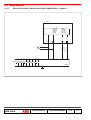
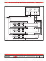
5.17. WIRING DIAGRAMS ............................................................................................................................................. 46
5.17.1. PR112-PR113-PR121-PR122-PR123-PR331-PR332-PR333 + PR021/K .................................................... 46
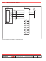
5.17.2. PR113/P-PR121/P-PR122/P-PR123/P-PR331/P-PR332/P-PR333/P+ 3 PR021/K units .............................. 47
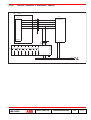
5.17.3. PR212/P or PR212MP + PR021/K .................................................................................................................... 48
5.17.4. PR212/P + PR212/D-L or PR212/D-M + PR021/K ........................................................................................... 49
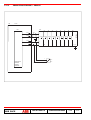
5.17.5. PR222-PR223-PR222MP + PR021/K ............................................................................................................... 50
6.
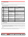
TROUBLESHOOTING ..................................................................................................................52
6.1.
IN CASE OF FAULT ............................................................................................................................................... 52
ABB SACE
SACE PR021/K
1SDH000559R0002
L3016
3/52
1. General information
1.1.
Foreword
Carefully read the whole of this document before installation and start-up of the PR021/K unit.
The PR021/K unit, connected to the Isomax, Emax and Tmax series protection units, allows signalling of various events
which may occur during normal operation of the connected protection unit.
In these events, the PR021/K unit operates the internal relays fitted with power contacts (par. 2.5).
The PR021/K unit also features (only in combination with the protection relays fitted to the Emax series) the ‘Load control’
function. For further information on the ‘Load control’ function, as well as the settings necessary to use this protection,
consult the user manual for the protection relays PR112, PR113, PR122 and PR123.
For correct use and operation of protection units interfaced with the PR021/K unit, the following documents must be
consulted:
•
•
•
•
•
•
•
•
•
•
•
•
•
•
•
Kit sheet of PR212/P protection unit (doc. no. RH0062)
Kit sheet of PR212MP protection unit (doc. no. RH0063)
Kit sheet of PR222MP protection unit (doc. no. 1SDH000436R0506)
User manual for PR112/P protection unit (doc. no. RH0288 for IEC version or RH0109 for UL version)
User manual for PR113/P protection unit (doc. no. RH0288 for IEC version or RH0109 for UL version)
User manual for PR222DS protection unit (doc. no. 1SDH000436R0502 for IEC version or 1SDH000549R0001 for UL
version)
User manual for PR223EF protection unit (doc. no. 1SDH000538R0001 for IEC version)
User manual for PR121/P protection unit (doc. no. 1SDH000460R0001 for IEC version or 1SDH000532R002 for UL
version)
User manual for PR122/P protection unit (doc. no. 1SDH000460R0001 for IEC version or 1SDH000532R002 for UL
version)
User manual for PR123/P protection unit (doc. no. 1SDH000460R0001 for IEC version or 1SDH000532R002 for UL
version)
User manual for PR331/P protection unit (doc. no. 1SDH000587R0001 for IEC version or ????????????????? for UL
version)
User manual for PR332/P protection unit (doc. no. 1SDH000587R0001 for IEC version or ????????????????? for UL
version)
User manual for PR333/P protection unit (doc. no. 1SDH000587R0001 for IEC version or ????????????????? for UL
version)
ABB SACE Isomax technical catalogue
ABB SACE Emax technical catalogue
ABB SACE
SACE PR021/K
1SDH000559R0002
L3016
4/52
1.2.
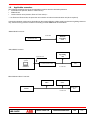
Applicable scenarios
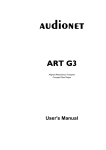
The following block diagrams show the applicable scenarios and the relationship between:
• Protection units (Isomax, Emax or Tmax series)**
• PR021/K unit
• Communication units (Isomax, Emax or Tmax series)**
**: for Emax and Tmax series, the protection unit contains an internal communication unit (when required).
Connections between various units, depending on the scenario (Master or Slave mode) are shown as a guiding reference
only, therefore wiring must be carried out according to official ABB SACE documentation.
“Master Mode” scenario:
Local bus
PR021/K
Signalling
unit
Protection unit
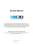
“Slave Mode” scenario:
PR021/K
Signalling
unit
System bus
Remote supervision
system
Protection
unit
Communication unit
Local bus
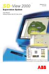
Mixed “Master+Slave” scenario:
PR021/K
Slave
PR021/K
Slave
PR021/K
Master
Protection
unit
Local bus
ABB SACE
SACE PR021/K
1SDH000559R0002
L3016
5/52
2. Technical specifications
2.1.
Electrical characteristics
Active operation:
MTBF (MIL-HDBK-217E) expected:
2.1.1.
Maximum 5s after power on
15 years at 45°C
Auxiliary power supply
As the Vaux must be isolated from earth, it is necessary to use ‘galvanically separate converters’ conforming to IEC
60950 (UL1950) or equivalent Std. [which guarantee a common mode current or leakage current (see IEC 478/1, CEI 22/
3) not greater than 3.5mA], IEC 60364-41 and CEI 64-8.
2.2.
Mechanical characteristics
Casing:
Protection grade:
Dimensions:
Weight:
2.3.
Polyamide plastic (no metal parts)
IP20
95 x 53 x 112mm (h x l x d)
330g (including 2 front connectors)
Environmental conditions
Operating environmental temperature:
Storage temperature:
Relative humidity:
Atmospheric pressure:
2.4.
-5°C ... +70°C
-40°C ... +90°C
5 ... 90% (without condensation)
1bar, 0…2000m
Communication Bus
Exclusive ABB SACE communication bus (local bus)
2.5.
Internal relay characteristics
Type:
Maximum switching capacity:
Maximum switching voltage:
Maximum switching current:
Breaking power (UL/CSA) @ 30VDC (resistive load):
Breaking power (UL/CSA) @ 250VAC (resistive load):
Contact/coil isolation:
ABB SACE
SACE PR021/K
Monostable STDP
100W / 1250VA (resistive load)
130VDC / 250VAC
5A
3.3A
5A
2000V eff (1 min. @ 50Hz)
1SDH000559R0002
L3016
6/52
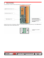
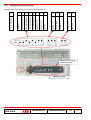
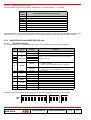
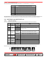
3. User interface
One push-button, ten LEDs and two terminal boxes are provided on unit’s front panel.
Terminal boxes (see par. 3.3)
Push-button (see par. 3.1)
The area bordered by a
dashed line is intended for
the possible application of a
customizable adhesive
rating plate
LEDs (see par. 3.2)
Should the user wish to customize the LEDs, the customizable adhesive rating plate may be used (RE0433/001),
supplied together with the SACE PR021/K unit.
Areas to be cutomized
by user
ABB SACE
SACE PR021/K
1SDH000559R0002
L3016
7/52
3.1.
Using the push-buttons
• Reset:
Press to reset the PR021/K hardware.
3.2.
Optical signals
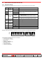
Description of events signalled by the LEDs K51/1...K51/8
Description of LEDs
K51/1 (green)
K51/2 (green)
K51/3 (green)
K51/4 (green)
K51/5 (green)
K51/6 (green)
K51/7 (green)
K51/8 (green)
PR021/K Operating conditions
LED state
Off
On
Contact
Contact
Contact
Contact
Contact
Contact
Contact
Contact
K51/1 open
K51/2 open
K51/3 open
K51/4 open
K51/5 open
K51/6 open
K51/7 open
K51/8 open
Contact
Contact
Contact
Contact
Contact
Contact
Contact
Contact
Flashing
K51/1 closed
K51/2 closed
K51/3 closed
K51/4 closed
K51/5 closed
K51/6 closed
K51/7 closed
K51/8 closed
---------
Description of events signalled by the LEDs PW/WD and TX/RX
PR021/K Operating conditions
Description of LEDs
PW/WD
TX/RX
GREEN
GREEN
GREEN
GREEN
GREEN
GREEN
GREEN
RED
R/V 2Hz
R/V 2Hz
R/V 2Hz
OFF
OFF
OFF
ON
4 flashes (*)
3 flashes (*)
2 flashes (*)
1 flash (*)
BLINK
XX
OFF
ON
2Hz flashing
OFF
ON
Meaning
If PR021/K is Slave then there is no communication
Not contemplated
Bus KO
Failure to identify the protection unit
Indicates that the Dip-switch K51 Dis/En is in the ON position
Indicates that the Dip-switch TEST Dis/En is in the ON position
Operating mode
WD hardware error
Programming Mode
Programming successfully completed
Programming failed
Unit off
Not contemplated
Caption:
XX = don’t care
BLINK = Flashing synchronized with activity of the local bus (the LED is on for 1 ms for each message received or transmitted)
R/V 2Hz = intermittent red/green lighting at 2Hz.
(*) Each flash is equivalent to relevant LED lighting for 200 ms, with a repetition period of 2s. The following priorities are
introduced to handle cases in which more than one signal is active:
ABB SACE
SACE PR021/K
1SDH000559R0002
L3016
8/52
Signal
Bus KO
Missing identification
K51 Dis/En
Test Dis/En
•
•
•
•
Priority
high priority
low priority
The LED test, consisting of all LEDs lighting up in sequence, takes place when the PR021/K unit is switched on;
the LED status is subsequently linked to normal unit operation.
Any LED lighting state which does not conform with the above conditions, probably indicates a malfunction of the
SACE PR021/K unit.
The indications given in the above table are with Vaux installed.
For further details of possible malfunction conditions, see par. 6.
3.3.
Terminal boxes
Connections 1...26 inputs and outputs of PR021/K unit (see pars. 5.1 and 5.2).
ABB SACE
SACE PR021/K
1SDH000559R0002
L3016
9/52
4. Special functions
4.1.
Reset
The PR021/K unit can be reset by pressing the ‘Reset’ push-button on the front panel of the unit (see par. 3.1).
This type of reset restarts the Sw of the PR021/K unit (the data stored in the RAM are erased).
4.2.
Reset signals
“Reset signals” causes the internal relays (K51/1...8) to be returned to their rest condition (contact open).
If the “AUTOMATIC RESET” function is not selected, to reset the signals, proceed as follows:
- carry out a reset (see par. 4.1), if the applicable scenario is “PR021/K in Master mode” (see par. 1.2)
- send a “Trip Reset “ command from the remote supervision system
- carry out a reset (see par. 4.1), if the applicable scenario is “PR021/K in Slave mode” (see par. 1.2), on the Emax series
protection unit (PR112 or PR113).
If the “AUTOMATIC RESET” function is selected, to reset the signals simply carry out a trip reset on the protection unit
and the signals on the PR021/K unit will also be reset automatically.
4.3.
Self-test function
To carry out the self-test, dip-switch no. 1 must be set to ON (see par. 5.3) then the reset push-button is pressed.
The self-test switches all 8 internal relays of the unit in sequence, and activates the related indicator LED
K51/1...K51/8 (see par. 3.2).
The Tx/Rx LED lights on each switching, and once the self-test is finished, it will flash according to the indications listed
in par. 3.2.
The self-test takes approx. 10s, thereafter the SACE PR021/K unit automatically returns to normal operation.
N.B. If dip-switch no. 1 is ON, the Self-test function is also activated when the PR021/K unit is powered on.
4.4.
Stand-by function
To select the Stand-by mode, dip-switch no. 8 must be set to ON (see par. 5.3) then the reset push-button is pressed;
in this operating mode, the internal relays of the unit will not be switched (but the related indicator LEDs K51/1...K51/8
will still light).
While operating in Stand-by mode, the Tx/Rx LED will flash according to the instructions listed in par. 3.2.
This function is used when the protection unit is being tested (for example with PR010/T unit) and switching of the relays
of the PR021/K unit is not desired.
N.B. If dip-switch no. 8 is ON, the Stand-by function is also activated when the PR021/K unit is powered on.
ABB SACE
SACE PR021/K
1SDH000559R0002
L3016
10/52
4.5.
Operating Mode
Depending on the setting of the dip switches and the protection unit connected, one of three operating modes may be
selected. The Signals section of each protection unit includes signal tables for each of the operating modes.
A description of the operating modes is given below.
4.5.1. Normal mode
4.5.1.1.
Normal mode with AUTOMATIC RESET disabled
To disable Automatic Reset, dip-switch no. 10 will be set to MAN (see par. 5.3), thereafter press the reset push-button
or switch PR021/K off and on.
In this operating mode each contact is associated with an event that causes the contact to close; with some contacts,
the associated event can be selected from two events by setting a dip switch (dip switch nos. 2, 3, 4).
When the protection release trips, the status of the contacts is “frozen” (any change in status of the protection is not
reflected in a change in status of the contacts). In this status, only the “protection release TRIP alarm” contact and the
contact that represents the protection that caused the trip, will be closed. For example, if protection S (selective shortcircuit) trips, the “protection release TRIP alarm” contact and the “Protection S trip (selective short-circuit)” contact will
be closed.
You can exit from the “frozen” status by resetting the signals (see par. 4.2).
4.5.1.2.
Normal mode with AUTOMATIC RESET enabled
To select the Automatic Reset function, dip-switch no. 10 will be set to AUT (see par. 5.3), thereafter press the reset
push-button or switch PR021/K off and on.
In this operating mode, the signals are the same as in Normal mode (see par. 4.5.1.1), the only difference being that, to
exit from “frozen” status following a TRIP, the trip can be directly reset on the protection unit (see user manual of the
protection unit used).
4.5.2. Latch mode
To select the Latch function, dip-switch no. 11 must be set to ON (see par. 5.3) and the reset button then be pressed or
the PR021/K unit be switched off and on
In this mode, the signals associated with each individual contact, once activated, are maintained (self-retaining of
contacts) until the signals have been reset (see par. 4.2).
N.B. When Latch mode is activated, the automatic reset function is automatically disabled irrespective of the setting
of dip-switch no. 10.
4.5.3. User mode
To select the User function, dip-switch no. 5 must be set to B (see par. 5.3) and the reset button then be pressed or the
PR021/K unit be switched off and on
In this mode, all contacts from K51/1 to K51/8 - excluding contact K51/5 - are solely associated with the function
selected on the protection unit (refer to user manual of the protection unit used); contact K51/5 is always associated with
the “Communication problems on local bus (KO bus)” indication.
N.B. When User mode is activated, the automatic reset and Latch mode functions are automatically disabled irrespective of the setting of dip-switches no. 10 and no. 11
ABB SACE
SACE PR021/K
1SDH000559R0002
L3016
11/52
5. Installation and setup
5.1.
Installation instructions
Mount on standard 35mm guide (DIN EN50022 type TS 35 x 15mm).
For the removable front connectors use cables with conductors having a cross-section from:
- 0.5 to 1.5mm2 (AWG 22...14) for connections to terminals 1...10;
- 0.5 to 2.5mm2 (AWG 22...12) for connections to terminals 11...26 (maximum current for each terminal is 5A continuous
rating, and 10A for a maximum of 2 seconds).
An earth terminal is provided on a front connector, to connect the electronic circuit to the installation earth.
Dielectric strength tests must not be carried out on the inputs and outputs of the PR021/K unit.
Although the PR021/K unit can be installed in the circuit-breaker compartment, it is good practice to install the unit in the
instrument compartment on the switchboard.
5.2.
Connections
Carefully study the relevant wiring diagrams for wiring the terminals.
For the dedicated inputs and outputs, wiring other than that described in the official ABB SACE wiring diagrams, is not
allowed.
ABB SACE
SACE PR021/K
1SDH000559R0002
L3016
12/52
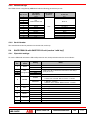
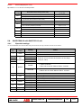
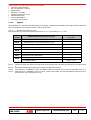
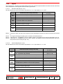
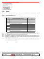
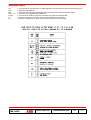
5.3.
Dip-switch settings
After correctly wiring all front connections, it is necessary to set the dip-switches on the top of the PR021/K unit.
The criteria for wiring the front connections and for dip-switch setting, depend upon the type of protection unit connected
to the PR021/K unit; the following paragraphs detail the possible configurations.
N.B.: dip-switch reading is carried out at “power on” or after a hardware reset (pressing front “Reset” button) and is active
after start-up.
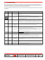
Dip-sw no.
Dip-sw name
Settable values
1
TEST
DIS. = self-test disabled
EN. = self-test enabled
K51
Configuration
A= type A signal
B= type B signal
MODE
SLAVE = Slave mode
MASTER = Master mode
BAUD
19.2kbit/s = baud rate
19200bit/s
38.4kbit/s = baud rate
38400bit/s
Setting of the transmission speed must be equal to that of the connected protection unit.
Normal operating mode ensures that the K51 contacts switch when the conditions which normally cause
switching exist (normal operating) and the related indicator LED lights.
Stand-by mode ensures that the K51 contacts do not switch under any circumstances, even under conditions
which would normally cause switching (the indicator LEDs K51/1...K51/8 will still light).
If set to ON (Stand-by) the unit is not able to carry out a self-test (performs the self-test by activating the LEDs
only).
For normal operating mode, set this dip-switch to OFF.
2
3
4
5
6
7
Notes
The "Self-test" function switches all 8 internal relays in sequence.
The Tx LED lights on each switching, and will flash once the self-test is finished according to the indications
listed in par. 3.2.
For normal operating mode, set this dip-switch to OFF.
Depending on the type of protection unit to which the PR021/K unit is connected, the signal of the event
associated with switching of some contacts (K51) may be chosen from two alternatives (A or B).
N.B. For some protection units, an alternative which can be selected using the dip-switches is not provided. In
this case the event associated with each contact is unique (defined by ABB SACE), and is independent of the
position of the dip-switch (OFF or ON).
Setting to Master mode is necessary when the PR021/K unit is combined with a protection unit without a
communication unit (see "scenario PR021/K in Master mode" and mixed "Master+Slave" scenario, par. 1.2).
Setting to Slave mode is necessary when the PR021/K unit is connected to a protection unit and a master
communication unit (see "scenario PR021/K in Slave mode" and mixed "Master+Slave" scenario, par. 1.2).
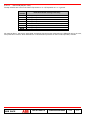
8
K51/
EN.= Normal mode
DIS.= Stand-by mode
9
PROG.
OFF = Operating mode
ON = Programming mode
10
RESET
MAN = manual reset
AUTO = automatic reset
This dip-switch is used to select the reset mode.
Manual reset: in the case of a trip, the signals are "frozen" until a reset is carried out (see par. 4.2)
Automatic reset: the signals of a trip are reset automatically when the trip on the protection unit is reset. In this
case, to reset the signals of the PR021/K unit,
. the trip signals on the protection unit must be reset.
11
LATCH
OFF = latch OFF
ON = latch ON
If Latch is enabled, the signals of each individual relay are maintained (self-retained) and can only be reset by a
.
reset command (see par. 4.2).
12
Term.
13
N.U.
ABB SACE
For ABB SACE use only.
For normal operating mode, set this dip-switch to OFF.
OFF = Termination switched
Turn (ON) to terminate the local bus with a 120 Ω resistance
off
The choice depends on the actual position of the PR021/K unit on the backbone of the communication system.
ON = Termination switched on
OFF = - ON = - -
Not used.
For normal operating mode, set this dip-switch to OFF.
SACE PR021/K
1SDH000559R0002
L3016
13/52
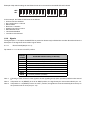
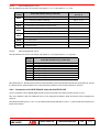
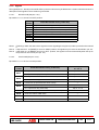
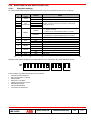
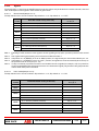
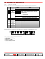
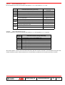
5.3.1. Example of dip-switch setting
No.
1
2
3
4
5
6
7
8
9
10
11
12
13
Dip-sw description
TEST: EN
K51 Configuration: B
K51 Configuration: A
K51 Configuration: B
K51 Configuration: A
MODE: MASTER
BAUD: 19.2kb/s
K51/: EN.
PROG.: OFF
RESET: MAN
LATCH: OFF
Term.: OFF
N.U.: OFF
Example of dip-switch setting for connecting the PR021/K unit.
Dip-switches for setting
the operating mode
PR021/K top view
ABB SACE
SACE PR021/K
1SDH000559R0002
L3016
14/52
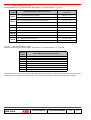
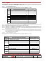
5.3.2. Default settings
The PR021/K unit is supplied by ABB SACE with the following parameters pre-set:
Dip-sw no.
1
2
3
4
5
6
7
8
9
10
11
12
13
Dip-switch
description
Dip-switch
position
V alue set
TES T
DIS .
K51
CONFIGURATION
M ode A
MODE
BAUD
K51/
P ROG.
RES ET
LATCH
Term.
N.U.
S LAV E
19.2kbit/s
EN.
OFF
M AN
OFF
OFF
--
OFF
5.3.3. Serial Number
The Serial Number label is positioned on the left side, at the top.
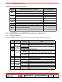
5.4.
SACE PR021/K with SACE PR112 unit (version “with key”)
5.4.1. Dip-switch settings
To use the PR021/K unit with the PR112/P protection unit, the dip-switches must be set as follows:
Dip-sw
no.
Dip-sw
name
1
TEST
2
3
4
5
K51
Configuration
6
MODE
Setting
DIS.
EN.
A/B
A/B
A/B
A
SLAVE
MASTER
7
BAUD
8
K51/
9
PROG.
10
RESET
11
LATCH
12
13
Term.
N.U.
ABB SACE
19.2kbit/s
EN.
DIS.
OFF
MAN
AUT
OFF
ON
OFF
OFF
Notes
Self-test enabled
Self-test disabled
Select A or B to choose the functions of the relays
(see par. 5.5.2)
Not used, set A
• "Slave" scenario
• Slave unit in mixed "Master+Slave" scenario
• "Master" scenario
• Master unit in mixed "Master+Slave" scenario
Set 19.2 kbit/s
Operating mode
Stand-by mode enabled
Set this dip-switch to OFF
Manual Reset mode
Automatic Reset mode
Normal mode
Latch mode
See par. 5.3
Not used
SACE PR021/K
1SDH000559R0002
L3016
15/52
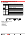
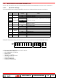
Example of dip-switch settings for the PR021/K unit to be connected to the SACE PR112/P release
OFFF
ON
11
22
33
4
4
55
66
77
88
9
9
10 11
11
10
12 13
13
12
In the example, the PR021/K has been set as follows:
• Self-test function disabled
• K51 configuration = A-A-A-A
• Master mode
• Baud rate = 19.2Kb/s
• Stand-by function not active
• Manual Reset mode
• Latch mode disabled
• Local bus not terminated
5.4.2. Signals
The signals (K51/1...K51/8) for the SACE PR112 protection release may be divided into 2 modes: Normal and Latch. A
description of the signals in these modes is given below.
5.4.1.1.
Normal mode (see par. 4.5.1)
Dip-switch no. 11 to be set to its OFF position.
Electric
contact
Note 1:
Note 2:
Note 3:
Event that caused closing of the relay
K51/1
L protection alarm or trip (overload)
K51/2
S protection alarm or trip (selective short-circuit)
K51/3
I protection trip (instantaneous short-circuit)
K51/4
G protection alarm or trip (earth fault)
K51/5
Communication problems on the local bus (bus KO)
K51/6
Internal overtemperature alarm or trip
K51/7
Protection release TRIP alarm
K51/8
L function prealarm (overload)
Following a TRIP, the status of the signals is frozen signalling the trip (K51/7) and the protection that caused
it.
If dip switch no. 10 (RESET) is set to its “MAN” position, the signals may be reset as described in par. 4.2.
If dip switch no. 10 (RESET) is set to its “AUT” position, the signals are reset automatically when the trip on
the protection unit is reset (see par. 4.2).
5.4.1.2.
Latch mode (see par. 4.5.2)
Dip-switch no. 11 to be set to its ON position.
Electric
contact
K51/1
K51/2
K51/3
K51/4
5.5.
Selection of dip-switches
no. 2, 3, 4
Event that caused closing of the relay
A = L protection alarm (overload)
dip no. 2 = A
B = L protection trip (overload)
dip no. 2 = B
A = S protection alarm (selective short-circuit)
dip no. 3 = A
B = S protection trip (selective short-circuit)
dip no. 3 = B
I protection trip (instantaneous short-circuit)
---
A = G protection alarm (earth fault)
dip no. 4 = A
B = G protection trip (earth fault)
dip no. 4 = B
K51/5
Communication problems on the local bus (bus KO)
K51/6
Internal overtemperature alarm
---
K51/7
Protection release TRIP alarm
---
K51/8
L function prealarm (overload)
---
SACE PR021/K with SACE PR112 unit (version “without key”)
5.5.1. Dip-switch settings
To use the PR021/K unit with the PR112/P protection unit, the dip-switches must be set as follows:
Dip-sw
no.
Dip-sw
name
1
TEST
2
3
4
5
K51
Configuration
6
MODE
Setting
DIS.
EN.
A/B
A/B
A/B
A
SLAVE
MASTER
7
BAUD
8
K51/
9
PROG.
10
RESET
11
LATCH
12
13
Term.
N.U.
ABB SACE
19.2kbit/s
EN.
DIS.
OFF
MAN
AUT
OFF
ON
OFF
OFF
Notes
Self-test enabled
Self-test disabled
Select A or B to choose the functions of the relays
(see par. 5.4.2)
Not used, set A
• "Slave" scenario
• Slave unit in mixed "Master+Slave" scenario
• "Master" scenario
• Master unit in mixed "Master+Slave" scenario
Set 19.2 kbit/s
Operating mode
Stand-by mode enabled
Set this dip-switch to OFF
Manual Reset mode
Automatic Reset mode
Normal mode
Latch mode
See par. 5.3
Not used
SACE PR021/K
1SDH000559R0002
L3016
17/52
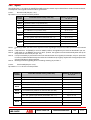
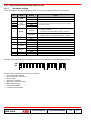
Example of dip-switch settings for the PR021/K unit to be connected to the SACE PR112/P release
OFF
ON
11
22
33
55
44
66
7
7
88
10 11
11
99 10
12 13
13
12
In the example, the PR021/K has been set as follows:
• Self-test function disabled
• K51 configuration = A-A-A-A
• Master mode
• Baud rate = 19.2Kb/s
• Stand-by function not active
• Manual Reset mode
• Latch mode disabled
• Local bus not terminated
5.5.2. Signals
The signals (K51/1...K51/8) for the SACE PR112 protection release may be divided into 2 modes: Normal and Latch. A
description of the signals in these modes is given below.
5.5.2.1.
Normal mode (see par. 4.5.1)
Dip-switch no. 11 to be set to its OFF position.
Electric
contact
L protection alarm or trip (overload)
---
K51/2
S protection alarm or trip (selective short-circuit)
---
K51/3
I protection trip (instantaneous short-circuit)
---
K51/5
Note 2:
Note 3:
Note 4:
Note 5:
Selection of dip-switches
no. 2, 3, 4
K51/1
K51/4
Note 1:
Event that caused closing of the relay
A = G protection alarm or trip (earth fault)
dip no. 2 = A
B = L function prealarm (overload)
dip no. 2 = B
Communication problems on the local bus (bus KO)
dip no. 3 = A
Internal overtemperature alarm or trip
dip no. 3 = B
K51/6
LC1 load control (Note 2)
---
K51/7
Protection release TRIP alarm
---
K51/8
LC2 load control (Note 2)
---
Following a TRIP, the status of the signals is frozen signalling the trip (K51/7) and the protection that caused
it.
The signals bearing this marking are not frozen as indicated in Note 1.
If dip switch no. 10 (RESET) is set to its “MAN” position, the signals may be reset as described in par. 4.2.
If dip switch no. 10 (RESET) is set to its “AUT” position, the signals are reset automatically when the trip on
the protection unit is reset (see par. 4.2).
If a trip is caused by a protection function not included in the set of signals (for example, a trip for “protection
G” has occurred but the K51/4 relay was set for the “Function L prealarm” signal), only the K51/7 relay (the
protection release TRIP alarm) will be switched.
ABB SACE
SACE PR021/K
1SDH000559R0002
L3016
18/52
5.5.2.2.
Latch mode (see par. 4.5.2)
Dip-switch no. 11 to be set to its ON position.
Electric
contact
K51/1
A = L protection alarm (overload)
dip no. 4 = A
B = L protection trip (overload)
dip no. 4 = B
K51/2
S protection alarm (selective short-circuit)
---
K51/3
I protection trip (instantaneous short-circuit)
---
K51/4
K51/5
5.6.
Selection of dip-switches
no. 2, 3, 4
Event that caused closing of the relay
A = G protection alarm (earth fault)
dip no. 2 = A
B = L function prealarm (overload)
dip no. 2 = B
A = Communication problems on the local bus (bus KO)
dip no. 3 = A
B = Internal overtemperature alarm
dip no. 3 = B
K51/6
LC1 load control
---
K51/7
Protection release TRIP alarm
---
K51/8
LC2 load control
---
SACE PR021/K with SACE PR113 unit
5.6.1.
Dip-switch settings
To use the PR021/K unit with the PR113/P protection unit, the dip-switches must be set as follows:
Dip-sw
no.
Dip-sw
name
1
TEST
2
3
4
5
K51
Configuration
6
DIS.
EN.
A/B
A/B
A/B
A/B
BAUD
8
K51/
9
PROG.
10
RESET
11
LATCH
12
13
Term.
N.U.
Notes
Self-test enabled
Self-test disabled
Select A or B to choose the functions of the relays
(see par. 5.6.2)
SLAVE
• "Slave" scenario
• Slave unit in mixed "Master+Slave" scenario
MASTER
• "Master" scenario
• Master unit in mixed "Master+Slave" scenario
MODE
7
ABB SACE
Setting
38.4kb/s
EN.
DIS.
OFF
MAN
AUT
OFF
ON
OFF
OFF
Set 38.4 kbit/s
Operating mode
Stand-by mode enabled
Set this dip-switch to OFF
Manual Reset mode
Automatic Reset mode
Normal mode
Latch mode
See par. 5.3
Not used
SACE PR021/K
1SDH000559R0002
L3016
19/52
Example of dip-switch settings for the PR021/K unit to be connected to the SACE PR113/P release
OFF
ON
1
2
3
4
5
6
7
9
8
10
11
12
13
In the example, the PR021/K has been set as follows:
• Self-test function disabled
• K51 configuration = A-A-A-A
• Master mode
• Baud rate = 38.4Kb/s
• Stand-by function not active
• Automatic Reset mode
• Latch mode disabled
• Local bus not terminated
5.6.2. Signals
The signals (K51/1...K51/8) for the SACE PR113 protection release may be divided into 3 modes: Normal, Latch and
User. A description of the signals in these modes is given below.
5.6.2.1.
Normal mode (see par. 4.5.1)
The dip-switches are to be set as follows: Dip-switch no. 5 = A, Dip-switch no. 11 = OFF.
Electric
contact
K51/1
Note 3:
Note 4:
Note 5:
A = L protection alarm or trip (overload)
dip no. 2 = A
B = L function prealarm (overload)
dip no. 2 = B
S protection alarm or trip (selective short-circuit)
---
K51/3
I protection trip (instantaneous short-circuit)
---
K51/5
Note 2:
Selection of dip-switches
no. 2, 3, 4
K51/2
K51/4
Note 1:
Event that caused closing of the relay
A = G protection alarm or trip (earth fault)
dip no. 3 = A
B = Minimum voltage coil (MT) energized
dip no. 3 = B
A = Communication problems on the local bus (bus KO)
dip no. 4 = A
B = Overtemperature alarm or trip
dip no. 4 = B
K51/6
LC1 load control (Note 2)
---
K51/7
Protection release TRIP alarm
---
K51/8
LC2 load control (Note 2)
---
Following a TRIP, the status of the signals is frozen signalling the trip (K51/7) and the protection that caused
it.
The signals bearing this marking are not frozen as indicated in Note 1, but follow the status indicated by the
protection irrespective of the protection trip.
If dip switch no. 10 (RESET) is set to its “MAN” position, the signals may be reset as described in par. 4.2.
If dip switch no. 10 (RESET) is set to its “AUT” position, the signals are reset automatically when the trip on
the protection unit is reset (see par. 4.2).
If a trip is caused by a protection function not included in the set of signals (for example, a trip for “protection
G” has occurred but the K51/4 relay was set for the “minimum voltage (MT) coil energized” signal), only the
K51/7 relay (the protection release TRIP alarm) will be switched.
ABB SACE
SACE PR021/K
1SDH000559R0002
L3016
20/52
5.6.2.2.
Latch mode (see par. 4.5.2)
The dip-switches are to be set as follows: Dip-switch no. 5 = A, Dip-switch no. 11 = ON.
Electric
contact
K51/1
Selection of dip-switches
no. 2, 3, 4
A = L protection alarm (overload)
dip no. 2 = A
B = L function prealarm (overload)
dip no. 2 = B
K51/2
S protection alarm (selective short-circuit)
---
K51/3
I protection trip (instantaneous short-circuit)
---
K51/4
K51/5
5.6.2.3.
Event that caused closing of the relay
A = G protection alarm (earth fault)
dip no. 3 = A
B = Minimum voltage coil (MT) energized
dip no. 3 = B
A = Communication problems on the local bus (bus KO)
dip no. 4 = A
B = Overtemperature prealarm
dip no. 4 = B
K51/6
LC1 load control
---
K51/7
Protection release TRIP alarm
---
K51/8
LC2 load control
---
User mode (see par. 4.5.3)
The dip-switches are to be set as follows: Dip-switch no. 5 = B, Dip-switch no. 11 = ignored.
Electric
contact
K51/1
K51/2
K51/3
K51/4
K51/5
K51/6
K51/7
K51/8
Event that caused closing of the relay
Configured by user on the PR113 unit
Configured by user on the PR113 unit
Configured by user on the PR113 unit
Configured by user on the PR113 unit
Communication problems on the local bus (bus KO)
Configured by user on the PR113 unit
Configured by user on the PR113 unit
Configured by user on the PR113 unit
All contacts (K51/1...K51/8) are associated exclusively with the function selected on the PR113 unit by the user, except
the K51/5 contact, which indicates the “Communication problems on the local bus (bus KO)” function.
5.6.3. Connection of 3 SACE PR021/K units with SACE PR113/P
Up to a maximum of three SACE PR021/K units can be connected to the PR113/P unit (see par. 5.14.4).
The only condition is that one PR021/K unit is to be configured as Master, while the other(s) is/are configured as
Slave(s).
This allows activating up to (7 + 8 + 3 =) 18 contacts without potential (K51/1, K51/2,...), plus 6 replicated contacts (see
Emax user manual).
ABB SACE
SACE PR021/K
1SDH000559R0002
L3016
21/52
5.7.
SACE PR021/K with SACE PR212/P unit
5.7.1. Dip-switch settings
To use the PR021/K unit with the PR212/P protection unit, the dip-switches must be set as follows:
Dip-sw
no.
Dip-sw
name
1
TEST
2
3
4
5
K51
Configuration
Setting
Notes
DIS.
EN.
A/B
A/B
A/B
A
Self-test enabled
Self-test disabled
Select A or B to choose the functions of the relays
(see par. 5.7.2)
Not used, set A
• "Slave" scenario
• Slave unit in mixed "Master+Slave" scenario
SLAVE
6
MODE
• "Master" scenario
• Master unit in mixed "Master+Slave" scenario
MASTER
7
BAUD
8
K51/
9
PROG.
10
RESET
11
LATCH
12
13
Term.
N.U.
38.4kb/s
EN.
DIS.
OFF
MAN
AUT
OFF
ON
OFF
OFF
Set 38.4 kbit/s
Operating mode
Stand-by mode enabled
Set this dip-switch to OFF
Manual Reset mode
Automatic Reset mode
Normal mode
Latch mode
See par. 5.3
Not used
Example of dip-switch settings for the PR021/K unit to be connected to the SACE PR212/P release
OFF
ON
1
2
3
4
5
6
7
8
9
10
11
12
13
In the example, the PR021/K has been set as follows:
• Self-test function disabled
• K51 configuration = A-A-A-A
• Master mode
• Baud rate = 38.4Kb/s
• Stand-by function not active
• Manual Reset mode
• Latch mode disabled
• Local bus not terminated
ABB SACE
SACE PR021/K
1SDH000559R0002
L3016
22/52
5.7.2. Signals
The signals (K51/1...K51/8) for the SACE PR212 protection release may be divided into 2 modes: Normal and Latch. A
description of the signals in these modes is given below.
5.7.2.1.
Normal mode (see par. 4.5.1)
Dip-switch no. 11 to be set to its OFF position.
Electric
contact
K51/1
K51/2
K51/3
K51/4
K51/5
K51/6
K51/7
K51/8
Note 1:
Note 2:
Note 3:
5.7.2.2.
Event that caused closing of the relay
L protection alarm or trip (overload)
S protection alarm or trip (selective short-circuit)
I protection trip (instantaneous short-circuit)
G protection alarm or trip (earth fault)
Communication problems on the local bus (bus KO)
Protection release TRIP alarm
Protection release TRIP alarm
L function prealarm (overload)
Following a TRIP, the status of the signals is frozen signalling the trip (K51/7) and the protection that caused
it.
If dip switch no. 10 (RESET) is set to its “MAN” position, the signals may be reset as described in par. 4.2.
If dip switch no. 10 (RESET) is set to its “AUT” position, the signals are reset automatically when the trip on
the protection unit is reset (see par. 4.2).
Latch mode (see par. 4.5.2)
Dip-switch no. 11 to be set to its ON position.
Electric
contact
K51/1
K51/2
K51/3
K51/4
Event that caused closing of the relay
Selection of dip-switches
no. 2, 3, 4
A = L protection alarm (overload)
dip no. 2 = A
B = L protection trip (overload)
dip no. 2 = B
A = S protection alarm (selective short-circuit)
dip no. 3 = A
B = S protection trip (selective short-circuit)
dip no. 3 = B
I protection trip (instantaneous short-circuit)
---
A = G protection alarm (earth fault)
dip no. 4 = A
B = G protection trip (earth fault)
dip no. 4 = B
K51/5
Communication problems on the local bus (bus KO)
---
K51/6
Protection release TRIP alarm
---
K51/7
Protection release TRIP alarm
---
K51/8
L function prealarm (overload)
---
ABB SACE
SACE PR021/K
1SDH000559R0002
L3016
23/52
5.8.
5.8.1.
SACE PR021/K with SACE PR212MP-PR222MP units
Dip-switch settings
To use the PR021/K unit with the PR212MP protection unit, the dip-switches must be set as follows:
Dip-sw
no.
Dip-sw name
1
TEST
2
3
4
5
6
7
Setting
DIS.
EN.
A/B
A/B
A/B
A
MASTER
38.4kb/s
EN.
DIS.
OFF
MAN
AUT
OFF
ON
OFF
OFF
K51
Configuration
MODE
BAUD
8
K51/
9
PROG.
10
RESET
11
LATCH
12
13
Term.
N.U.
Notes
Self-test enabled
Self-test disabled
Select A or B to choose the functions of the relays
(see par. 5.8.2)
Not used, set A
Set Master
Set 38.4 kbit/s
Operating mode
Stand-by mode enabled
Set this dip-switch to OFF
Manual Reset mode
Automatic Reset mode
Normal mode
Latch mode
See par. 5.3
Not used
Example of dip-switch settings for the PR021/K unit to be connected to the SACE PR212MP release
OFF
ON
1
2
3
4
5
6
7
8
9
10
11
12
13
In the example, the PR021/K has been set as follows:
• Self-test function disabled
• K51 configuration = A-A-A-A
• Master mode
• Baud rate = 38.4Kb/s
• Stand-by function not active
• Manual Reset mode
• Latch mode disabled
• Local bus not terminated
ABB SACE
SACE PR021/K
1SDH000559R0002
L3016
24/52
5.8.2.
Signals
The signals (K51/1...K51/8) for the SACE PR212MP protection release may be divided into 2 modes: Normal and Latch.
A description of the signals in these modes is given below.
5.8.2.1.
Normal mode (see par. 4.5.1)
Dip-switch no. 11 to be set to its OFF position.
Electric
contact
L protection alarm or trip (overload)
---
K51/2
R protection alarm or trip (locked rotor)
---
K51/3
I protection trip (instantaneous short-circuit)
---
K51/5
K51/6
K51/7
K51/8
Note 2:
Note 3:
Note 4:
Note 5:
Selection of dip-switches
no. 2, 3, 4
K51/1
K51/4
Note 1:
Event that caused closing of the relay
A = U protection alarm or trip (phase loss)
dip no. 2 = A
B = CW alarm or trip (contacts worn)
dip no. 2 = B
Communication problems on the local bus (bus KO)
---
A = PTC alarm or trip (motor overtemperature)
dip no. 3 = A
B = G.P. generic input status (activated if G.P. = 1)
dip no. 3 = B
Protection release TRIP alarm
---
A = L Function prealarm (overload)
dip no. 4 = A
B = Backup protection alarm (Note 5)
dip no. 4 = B
Following a TRIP, the status of the signals is frozen signalling the trip (K51/7) and the protection that caused
it.
If dip switch no. 10 (RESET) is set to its “MAN” position, the signals may be reset as described in par. 4.2.
If dip switch no. 10 (RESET) is set to its “AUT” position, the signals are reset automatically when the trip on
the protection unit is reset (see par. 4.2).
If a trip is caused by a protection function not included in the set of signals (for example, a trip for “protection
U” has occurred but the K51/4 relay was set for the “CW alarm or trip” signal), only the K51/7 relay (the protection
release TRIP alarm) will be switched.
Backup protection signalling does not undergo freezing as per Note 1.
5.8.2.2.
Latch mode (see par. 4.5.2)
Dip-switch no. 11 to be set to its ON position.
Electric
contact
Event that caused closing of the relay
Selection of dip-switches
no. 2, 3, 4
K51/1
L protection alarm (overload)
---
K51/2
R protection alarm (locked rotor)
---
K51/3
I protection trip (instantaneous short-circuit)
---
K51/4
K51/5
K51/6
K51/7
K51/8
ABB SACE
A = U protection alarm (phase loss)
dip no. 2 = A
B = CW alarm (contacts worn)
dip no. 2 = B
Communication problems on the local bus (bus KO)
---
A = PTC alarm or trip (motor overtemperature)
dip no. 3 = A
B = G.P. generic input status (activated if G.P. = 1)
dip no. 3 = B
Protection release TRIP alarm
---
A = L Function prealarm (overload)
dip no. 4 = A
B = Backup protection alarm
dip no. 4 = B
SACE PR021/K
1SDH000559R0002
L3016
25/52
5.9.
SACE PR021/K with SACE PR222DS unit
To work with the PR021/K unit, the communication baud rate of the PR222DS must be set to 19200 bit/s.
5.9.1. Dip-switch settings
To use the PR021/K unit with the PR222DS protection unit, the dip-switches must be set as follows:
Dip-sw
no.
Dip-sw
name
1
TEST
2
3
4
5
K51
Configuration
6
MODE
MASTER
7
BAUD
8
K51/
9
PROG.
10
RESET
11
LATCH
12
13
Term.
N.U.
19.2kb/s
EN.
DIS.
OFF
MAN
AUT
OFF
ON
OFF
OFF
Setting
Notes
DIS.
EN.
A/B
A/B
A/B
A
Self-test enabled
Self-test disabled
Select A or B to choose the functions of the relays
(see par. 5.9.2)
Not used, set A
With PR222DS, the only scenario available is the
Master scenario.
Set 19.2 kbit/s
Operating mode
Stand-by mode enabled
Set this dip-switch to OFF
Manual Reset mode
Automatic Reset mode
Normal mode
Latch mode
See par. 5.3
Not used
Example of dip-switch settings for the PR021/K unit to be connected to the SACE PR222DS release
OFF
ON
1
2
3
4
5
6
7
8
9
10
11
12
13
In the example, the PR021/K has been set as follows:
• Self-test function disabled
• K51 configuration = A-A-A-A
• Master mode
• Baud rate = 19.2Kb/s
• Stand-by function not active
• Manual Reset mode
• Latch mode disabled
• Local bus not terminated
ABB SACE
SACE PR021/K
1SDH000559R0002
L3016
26/52
5.9.2. Signals
The signals (K51/1...K51/8) for the SACE PR222DS protection release may be divided into 2 modes: Normal and Latch.
A description of the signals in these modes is given below.
5.9.2.1.
Normal mode (see par. 4.5.1)
Dip-switch no. 11 to be set to its OFF position.
Electric
contact
K51/1
K51/2
K51/3
K51/4
K51/5
K51/6
K51/7
K51/8
Note 1:
Note 2:
Note 3:
Note 4:
Event that caused closing of the relay
L protection alarm or trip (overload)
S protection alarm or trip (selective short-circuit)
I protection trip (instantaneous short-circuit)
G protection alarm or trip (earth fault)
Communication problems on the local bus (bus KO)
Protection release TRIP alarm
Protection release TRIP alarm
L function prealarm (overload)
Following a TRIP, the status of the signals is frozen signalling the trip (K51/7) and the protection that caused
it.
If dip switch no. 10 (RESET) is set to its “MAN” position, the signals may be reset as described in par. 4.2.
If dip switch no. 10 (RESET) is set to its “AUT” position, the signals are reset automatically when the trip on
the protection unit is reset (see par. 4.2).
Use of the PR010/T test unit interrupts communication with the PR021/K unit, which will signal a
communication error on the local bus by closing the K51/5 contact.
5.9.2.2.
Latch mode (see par. 4.5.2)
Dip-switch no. 11 to be set to its ON position.
Electric
contact
K51/1
K51/2
K51/3
K51/4
Event that caused closing of the relay
Selection of dip-switches
no. 2, 3, 4
A = L protection alarm (overload)
dip no. 2 = A
B = L protection trip (overload)
dip no. 2 = B
A = S protection alarm (selective short-circuit)
dip no. 3 = A
B = S protection trip (selective short-circuit)
dip no. 3 = B
I protection trip (instantaneous short-circuit)
---
A = G protection alarm (earth fault)
dip no. 4 = A
B = G protection trip (earth fault)
dip no. 4 = B
K51/5
Communication problems on the local bus (bus KO)
---
K51/6
Protection release TRIP alarm
---
K51/7
Protection release TRIP alarm
---
K51/8
L function prealarm (overload)
---
ABB SACE
SACE PR021/K
1SDH000559R0002
L3016
27/52
5.10. SACE PR021/K with SACE PR223EF unit
To work with the PR021/K unit, the communication baud rate of the PR223EF unit must be set to 19200 bit/s.
5.10.1.
Dip-switch settings
To use the PR021/K unit with the PR223EF protection unit, the dip-switches must be set as follows:
Dip-sw
no.
Dip-sw
name
1
TEST
2
3
4
5
K51
Configuration
6
MODE
MASTER
7
BAUD
8
K51/
9
PROG.
10
RESET
11
LATCH
12
13
Term.
N.U.
19.2kb/s
EN.
DIS.
OFF
MAN
AUT
OFF
ON
OFF
OFF
Setting
Notes
DIS.
EN.
A/B
A/B
A/B
A/B
Self-test enabled
Self-test disabled
Select A or B to choose the functions of the relays
(see par. 5.10.2)
With PR223EF, the only scenario available is the
Master scenario.
Set 19.2 kbit/s
Operating mode
Stand-by mode enabled
Set this dip-switch to OFF
Manual Reset mode
Automatic Reset mode
Normal mode
Latch mode
See par. 5.3
Not used
Example of dip-switch settings for the PR021/K unit to be connected to the SACE PR223EF release
OFF
ON
1
2
3
4
5
6
7
8
9
10
11
12
13
In the example, the PR021/K has been set as follows:
• Self-test function disabled
• K51 configuration = A-A-A-A
• Master mode
• Baud rate = 19.2Kb/s
• Stand-by function not active
• Manual Reset mode
• Latch mode disabled
• Local bus not terminated
ABB SACE
SACE PR021/K
1SDH000559R0002
L3016
28/52
5.10.2.
Signals
The signals (K51/1...K51/8) for the SACE PR223EF protection release may be divided into 3 modes: Normal, Latch and
User. A description of the signals in these modes is given below.
5.10.2.1.
Normal mode (see par. 4.5.1)
The dip-switches are to be set as follows: Dip-switch no. 5 = A, Dip-switch no. 11 = OFF.
Electric
contact
Note 2:
Note 3:
Note 4:
Note 5:
Selection of dip-switches
no. 2, 3, 4
K51/1
L protection alarm or trip (overload)
---
K51/2
S protection alarm or trip (selective short-circuit)
---
K51/3
I or EF protection trip (instantaneous short-circuit)
---
K51/4
G protection alarm or trip (earth fault)
---
K51/5
Communication problems on the local bus (bus KO)
---
K51/6
Backup protection alarm (Note 2)
---
K51/7
Protection release TRIP alarm
---
K51/8
Note 1:
Event that caused closing of the relay
A = L Function prealarm (overload)
dip no. 4 = A
B = Interlock alarm
dip no. 4 = B
Following a TRIP, the status of the signals is frozen signalling the trip (K51/7) and the protection that caused
it.
The signals bearing this marking are not frozen as indicated in Note 1.
If dip switch no. 10 (RESET) is set to its “MAN” position, the signals may be reset as described in par. 4.2.
If dip switch no. 10 (RESET) is set to its “AUT” position, the signals are reset automatically when the trip on
the protection unit is reset (see par. 4.2).
Use of the PR010/T test unit interrupts communication with the PR021/K unit, which will signal a
communication error on the local bus by closing the K51/5 contact.
5.10.2.2.
Latch mode (see par. 4.5.2)
The dip-switches are to be set as follows: Dip-switch no. 5 = A, Dip-switch no. 11 = ON.
Electric
contact
Event that caused closing of the relay
Selection of dip-switches
no. 2, 3, 4
A = L protection alarm (overload)
dip no. 2 = A
B = L protection trip (overload)
dip no. 2 = B
A = S protection alarm (selective short-circuit)
dip no. 3 = A
B = S protection trip (selective short-circuit)
dip no. 3 = B
K51/3
I protection trip (instantaneous short-circuit)
---
K51/4
G protection alarm (earth fault)
---
K51/5
Communication problems on the local bus (bus KO)
---
K51/6
Backup protection alarm
---
K51/7
Protection release TRIP alarm
---
K51/1
K51/2
K51/8
ABB SACE
A = L Function prealarm (overload)
dip no. 4 = A
B = Interlock alarm
dip no. 4 = B
SACE PR021/K
1SDH000559R0002
L3016
29/52
5.10.2.3.
User mode (see par. 4.5.3)
The dip-switches are to be set as follows: Dip-switch no. 5 = B, Dip-switch no. 11 = ignored.
Electric
contact
K51/1
K51/2
K51/3
K51/4
K51/5
K51/6
K51/7
K51/8
Event that caused closing of the relay
Configured by user on the PR223EF unit
Configured by user on the PR223EF unit
Configured by user on the PR223EF unit
Configured by user on the PR223EF unit
Communication problems on the local bus (bus KO)
Configured by user on the PR223EF unit
Configured by user on the PR223EF unit
Configured by user on the PR223EF unit
All contacts (K51/1...K51/8) are associated exclusively with the function selected on the PR223EF unit by the user,
except the K51/5 contact, which indicates the “Communication problems on the local bus (bus KO)” function.
5.11. SACE PR021/K with SACE PR121/P unit
5.11.1.
Dip-switch settings
To use the PR021/K unit with the PR121/P protection unit, the dip-switches must be set as follows:
Dip-sw
no.
Dip-sw
name
1
TEST
2
3
4
5
K51
Configuration
Setting
Notes
DIS.
EN.
A/B
A/B
A/B
A/B
Self-test enabled
Self-test disabled
Select A or B to choose the functions of the relays
(see par. 5.11.2)
• "Slave" scenario
• Slave unit in mixed "Master+Slave" scenario
SLAVE
6
MODE
• "Master" scenario
• Master unit in mixed "Master+Slave" scenario
Set 19.2 kbit/s
Operating mode
Stand-by mode enabled
Set this dip-switch to OFF
Manual Reset mode
Automatic Reset mode
Normal mode
Latch mode
See par. 5.3
Not used
MASTER
7
BAUD
8
K51/
9
PROG.
10
RESET
11
LATCH
12
13
Term.
N.U.
19.2kb/s
EN.
DIS.
OFF
MAN
AUT
OFF
ON
OFF
OFF
Example of dip-switch settings for the PR021/K unit to be connected to the SACE PR121/P release
OFF
ON
1
ABB SACE
2
3
4
5
6
7
8
SACE PR021/K
9
10
11
12
1SDH000559R0002
13
L3016
30/52
In the example, the PR021/K has been set as follows:
• Self-test function disabled
• K51 configuration = A-A-A-A
• Master mode
• Baud rate = 19.2Kb/s
• Stand-by function not active
• Manual Reset mode
• Latch mode disabled
• Local bus not terminated
5.11.2.
Signals
The signals (K51/1...K51/8) for the SACE PR121/P protection release may be divided into 3 modes: Normal, Latch and
User. A description of the signals in these modes is given below.
5.11.2.1.
Normal mode (see par. 4.5.1)
The dip-switches are to be set as follows: Dip-switch no. 5 = A, Dip-switch no. 11 = OFF.
Electric
contact
Note 2:
Note 3:
Note 4:
Selection of dip-switches
no. 2, 3, 4
K51/1
L protection alarm or trip (overload)
---
K51/2
S protection alarm or trip (selective short-circuit)
---
K51/3
I protection trip (instantaneous short-circuit)
---
K51/4
G protection alarm or trip (earth fault)
---
K51/5
Communication problems on the local bus (bus KO)
---
K51/6
L function prealarm (overload)
---
K51/7
Protection release TRIP alarm
---
K51/8
Note 1:
Event that caused closing of the relay
A = Backup protection alarm (Note 2)
dip no. 4 = A
B = Hardware alarm
dip no. 4 = B
Following a TRIP, the status of the signals is frozen signalling the trip (K51/7) and the protection that caused
it.
The signals bearing this marking are not frozen as indicated in Note 1.
If dip switch no. 10 (RESET) is set to its “MAN” position, the signals may be reset as described in par. 4.2.
If dip switch no. 10 (RESET) is set to its “AUT” position, the signals are reset automatically when the trip on
the protection unit is reset (see par. 4.2).
ABB SACE
SACE PR021/K
1SDH000559R0002
L3016
31/52
5.11.2.2.
Latch mode (see par. 4.5.2)
The dip-switches are to be set as follows: Dip-switch no. 5 = A, Dip-switch no. 11 = ON.
Electric
contact
Event that caused closing of the relay
Selection of dip-switches
no. 2, 3, 4
A = L protection alarm (overload)
dip no. 2 = A
B = L protection trip (overload)
dip no. 2 = B
A = S protection alarm (selective short-circuit)
dip no. 3 = A
B = S protection trip (selective short-circuit)
dip no. 3 = B
K51/3
I protection trip (instantaneous short-circuit)
---
K51/4
G protection alarm (earth fault)
---
K51/5
Communication problems on the local bus (bus KO)
---
K51/6
L function prealarm (overload)
---
K51/7
Protection release TRIP alarm
---
K51/1
K51/2
K51/8
A = Backup protection alarm
dip no. 4 = A
B = Hardware alarm
dip no. 4 = B
5.11.2.3.
User mode (see par. 4.5.3)
The dip-switches are to be set as follows: Dip-switch no. 5 = B, Dip-switch no. 11 = ignored.
Electric
contact
K51/1
K51/2
K51/3
K51/4
K51/5
K51/6
K51/7
K51/8
Event that caused closing of the relay
Configured by user on the PR121/P unit
Configured by user on the PR121/P unit
Configured by user on the PR121/P unit
Configured by user on the PR121/P unit
Communication problems on the local bus (bus KO)
Configured by user on the PR121/P unit
Configured by user on the PR121/P unit
Configured by user on the PR121/P unit
All contacts (K51/1...K51/8) are associated exclusively with the function selected on the PR121/P unit by the user,
except the K51/5 contact, which indicates the “Communication problems on the local bus (bus KO)” function.
ABB SACE
SACE PR021/K
1SDH000559R0002
L3016
32/52
5.12. SACE PR021/K with SACE PR122/P unit
5.12.1.
Dip-switch settings
To use the PR021/K unit with the PR122/P protection unit, the dip-switches must be set as follows:
Dip-sw
no.
Dip-sw
name
1
TEST
2
3
4
5
K51
Configuration
Setting
Notes
DIS.
EN.
A/B
A/B
A/B
A/B
Self-test enabled
Self-test disabled
Select A or B to choose the functions of the relays
(see par. 5.12.2)
• "Slave" scenario
• Slave unit in mixed "Master+Slave" scenario
SLAVE
6
MODE
• "Master" scenario
• Master unit in mixed "Master+Slave" scenario
Set 19.2 kbit/s
Operating mode
Stand-by mode enabled
Set this dip-switch to OFF
Manual Reset mode
Automatic Reset mode
Normal mode
Latch mode
See par. 5.3
Not used
MASTER
7
BAUD
8
K51/
9
PROG.
10
RESET
11
LATCH
12
13
Term.
N.U.
19.2kb/s
EN.
DIS.
OFF
MAN
AUT
OFF
ON
OFF
OFF
Example of dip-switch settings for the PR021/K unit to be connected to the SACE PR122/P release
OFF
ON
1
2
3
4
5
6
7
8
9
10
11
12
13
In the example, the PR021/K has been set as follows:
• Self-test function disabled
• K51 configuration = A-A-A-A
• Master mode
• Baud rate = 19.2Kb/s
• Stand-by function not active
• Manual Reset mode
• Latch mode disabled
• Local bus not terminated
ABB SACE
SACE PR021/K
1SDH000559R0002
L3016
33/52
5.12.2.
Signals
The signals (K51/1...K51/8) for the SACE PR122/P protection release may be divided into 3 modes: Normal, Latch and
User. A description of the signals in these modes is given below.
5.12.2.1.
Normal mode (see par. 4.5.1)
The dip-switches are to be set as follows: Dip-switch no. 5 = A, Dip-switch no. 11 = OFF.
Electric
contact
L protection alarm or trip (overload)
---
K51/2
S protection alarm or trip (selective short-circuit)
---
K51/3
I protection trip (instantaneous short-circuit)
---
K51/5
K51/6
K51/7
K51/8
Note 2:
Note 3:
Note 4:
Note 5:
Selection of dip-switches
no. 2, 3, 4
K51/1
K51/4
Note 1:
Event that caused closing of the relay
A = G protection alarm or trip (earth fault)
dip no. 2 = A
B = LC1 load control (Note 2)
dip no. 2 = B
Communication problems on the local bus (bus KO)
---
A = L Function prealarm (overload)
dip no. 3 = A
B = LC2 load control (Note 2)
dip no. 3 = B
Protection release TRIP alarm
---
A = Backup protection alarm (Note 2)
dip no. 4 = A
B = Hardware alarm
dip no. 4 = B
Following a TRIP, the status of the signals is frozen signalling the trip (K51/7) and the protection that caused
it.
The signals bearing this marking are not frozen as indicated in Note 1.
If dip switch no. 10 (RESET) is set to its “MAN” position, the signals may be reset as described in par. 4.2.
If dip switch no. 10 (RESET) is set to its “AUT” position, the signals are reset automatically when the trip on
the protection unit is reset (see par. 4.2).
If a trip is caused by a protection function not included in the set of signals (for example, a trip for “protection
G” has occurred but the K51/4 relay was set for the “LC1 load control” signal), only the K51/7 relay (the protection
release TRIP alarm) will be switched.
5.12.2.2.
Latch mode (see par. 4.5.2)
The dip-switches are to be set as follows: Dip-switch no. 5 = A, Dip-switch no. 11 = ON.
Electric
contact
Event that caused closing of the relay
Selection of dip-switches
no. 2, 3, 4
K51/1
L protection alarm (overload)
---
K51/2
S protection alarm (selective short-circuit)
---
K51/3
I protection trip (instantaneous short-circuit)
---
K51/4
K51/5
K51/6
K51/7
K51/8
ABB SACE
A = G protection alarm (earth fault)
dip no. 2 = A
B = LC1 load control
dip no. 2 = B
Communication problems on the local bus (bus KO)
---
A = L Function prealarm (overload)
dip no. 3 = A
B = LC2 load control
dip no. 3 = B
Protection release TRIP alarm
---
A = Backup protection alarm
dip no. 4 = A
B = Hardware alarm
dip no. 4 = B
SACE PR021/K
1SDH000559R0002
L3016
34/52
5.12.2.3.
User mode (see par. 4.5.3)
The dip-switches are to be set as follows: Dip-switch no. 5 = B, Dip-switch no. 11 = ignored.
Electric
contact
K51/1
K51/2
K51/3
K51/4
K51/5
K51/6
K51/7
K51/8
Event that caused closing of the relay
Configured by user on the PR122/P unit
Configured by user on the PR122/P unit
Configured by user on the PR122/P unit
Configured by user on the PR122/P unit
Communication problems on the local bus (bus KO)
Configured by user on the PR122/P unit
Configured by user on the PR122/P unit
Configured by user on the PR122/P unit
All contacts (K51/1...K51/8) are associated exclusively with the function selected on the PR122/P unit by the user,
except the K51/5 contact, which indicates the “Communication problems on the local bus (bus KO)” function.
5.13. SACE PR021/K with SACE PR123/P unit
5.13.1.
Dip-switch settings
To use the PR021/K unit with the PR123/P protection unit, the dip-switches must be set as follows:
Dip-sw
no.
Dip-sw
name
1
TEST
2
3
4
5
K51
Configuration
Setting
Notes
DIS.
EN.
A/B
A/B
A/B
A/B
Self-test enabled
Self-test disabled
Select A or B to choose the functions of the relays
(see par. 5.13.2)
• "Slave" scenario
• Slave unit in mixed "Master+Slave" scenario
SLAVE
6
MODE
• "Master" scenario
• Master unit in mixed "Master+Slave" scenario
Set 19.2 kbit/s
Operating mode
Stand-by mode enabled
Set this dip-switch to OFF
Manual Reset mode
Automatic Reset mode
Normal mode
Latch mode
See par. 5.3
Not used
MASTER
7
BAUD
8
K51/
9
PROG.
10
RESET
11
LATCH
12
13
Term.
N.U.
19.2kb/s
EN.
DIS.
OFF
MAN
AUT
OFF
ON
OFF
OFF
Example of dip-switch settings for the PR021/K unit to be connected to the SACE PR123/P release
OFF
ON
1
ABB SACE
2
3
4
5
6
7
8
SACE PR021/K
9
10
11
12
13
1SDH000559R0002
L3016
35/52
In the example, the PR021/K has been set as follows:
• Self-test function disabled
• K51 configuration = A-A-A-A
• Master mode
• Baud rate = 19.2Kb/s
• Stand-by function not active
• Manual Reset mode
• Latch mode disabled
• Local bus not terminated
5.13.2.
Signals
The signals (K51/1...K51/8) for the SACE PR123/P protection release may be divided into 3 modes: Normal, Latch and
User. A description of the signals in these modes is given below.
5.13.2.1.
Normal mode (see par. 4.5.1)
The dip-switches are to be set as follows: Dip-switch no. 5 = A, Dip-switch no. 11 = OFF.
Electric
contact
L protection alarm or trip (overload)
---
K51/2
S protection alarm or trip (selective short-circuit)
---
K51/3
I protection trip (instantaneous short-circuit)
---
K51/5
K51/6
K51/7
K51/8
Note 2:
Note 3:
Note 4:
Note 5:
Selection of dip-switches
no. 2, 3, 4
K51/1
K51/4
Note 1:
Event that caused closing of the relay
A = G protection alarm or trip (earth fault)
dip no. 2 = A
B = LC1 load control (Note 2)
dip no. 2 = B
Communication problems on the local bus (bus KO)
---
A = L Function prealarm (overload)
dip no. 3 = A
B = LC2 load control (Note 2)
dip no. 3 = B
Protection release TRIP alarm
---
A = Backup protection alarm (Note 2)
dip no. 4 = A
B = Hardware alarm
dip no. 4 = B
Following a TRIP, the status of the signals is frozen signalling the trip (K51/7) and the protection that caused
it.
The signals bearing this marking are not frozen as indicated in Note 1.
If dip switch no. 10 (RESET) is set to its “MAN” position, the signals may be reset as described in par. 4.2.
If dip switch no. 10 (RESET) is set to its “AUT” position, the signals are reset automatically when the trip on
the protection unit is reset (see par. 4.2).
If a trip is caused by a protection function not included in the set of signals (for example, a trip for “protection
G” has occurred but the K51/4 relay was set for the “LC1 load control” signal), only the K51/7 relay (the protection
release TRIP alarm) will be switched.
ABB SACE
SACE PR021/K
1SDH000559R0002
L3016
36/52
5.13.2.2.
Latch mode (see par. 4.5.2)
The dip-switches are to be set as follows: Dip-switch no. 5 = A, Dip-switch no. 11 = ON.
Electric
contact
Event that caused closing of the relay
Selection of dip-switches
no. 2, 3, 4
K51/1
L protection alarm (overload)
---
K51/2
S protection alarm (selective short-circuit)
---
K51/3
I protection trip (instantaneous short-circuit)
---
K51/4
K51/5
K51/6
K51/7
K51/8
A = G protection alarm (earth fault)
dip no. 2 = A
B = LC1 load control
dip no. 2 = B
Communication problems on the local bus (bus KO)
---
A = L Function prealarm (overload)
dip no. 3 = A
B = LC2 load control
dip no. 3 = B
Protection release TRIP alarm
---
A = Backup protection alarm
dip no. 4 = A
B = Hardware alarm
dip no. 4 = B
5.13.2.3.
User mode (see par. 4.5.3)
The dip-switches are to be set as follows: Dip-switch no. 5 = B, Dip-switch no. 11 = ignored.
Electric
contact
K51/1
K51/2
K51/3
K51/4
K51/5
K51/6
K51/7
K51/8
Event that caused closing of the relay
Configured by user on the PR123/P unit
Configured by user on the PR123/P unit
Configured by user on the PR123/P unit
Configured by user on the PR123/P unit
Communication problems on the local bus (bus KO)
Configured by user on the PR123/P unit
Configured by user on the PR123/P unit
Configured by user on the PR123/P unit
All contacts (K51/1...K51/8) are associated exclusively with the function selected on the PR123/P unit by the user,
except the K51/5 contact, which indicates the “Communication problems on the local bus (bus KO)” function.
ABB SACE
SACE PR021/K
1SDH000559R0002
L3016
37/52
5.14. SACE PR021/K with SACE PR331/P unit
5.14.1.
Dip-switch settings
To use the PR021/K unit with the PR331/P protection unit, the dip-switches must be set as follows:
Dip-sw
no.
Dip-sw
name
1
TEST
2
3
4
5
K51
Configuration
Setting
Notes
DIS.
EN.
A/B
A/B
A/B
A/B
Self-test enabled
Self-test disabled
Select A or B to choose the functions of the relays
(see par. 5.14.2)
• "Slave" scenario
• Slave unit in mixed "Master+Slave" scenario
SLAVE
6
MODE
• "Master" scenario
• Master unit in mixed "Master+Slave" scenario
Set 19.2 kbit/s
Operating mode
Stand-by mode enabled
Set this dip-switch to OFF
Manual Reset mode
Automatic Reset mode
Normal mode
Latch mode
See par. 5.3
Not used
MASTER
7
BAUD
8
K51/
9
PROG.
10
RESET
11
LATCH
12
13
Term.
N.U.
19.2kb/s
EN.
DIS.
OFF
MAN
AUT
OFF
ON
OFF
OFF
Example of dip-switch settings for the PR021/K unit to be connected to the SACE PR331/P release
OFF
ON
1
2
3
4
5
6
7
8
9
10
11
12
13
In the example, the PR021/K has been set as follows:
• Self-test function disabled
• K51 configuration = A-A-A-A
• Master mode
• Baud rate = 19.2Kb/s
• Stand-by function not active
• Manual Reset mode
• Latch mode disabled
• Local bus not terminated
ABB SACE
SACE PR021/K
1SDH000559R0002
L3016
38/52
5.14.2.
Signals
The signals (K51/1...K51/8) for the SACE PR331/P protection release may be divided into 3 modes: Normal, Latch and
User. A description of the signals in these modes is given below.
5.14.2.1.
Normal mode (see par. 4.5.1)
The dip-switches are to be set as follows: Dip-switch no. 5 = A, Dip-switch no. 11 = OFF.
Electric
contact
Note 2:
Note 3:
Note 4:
Selection of dip-switches
no. 2, 3, 4
K51/1
L protection alarm or trip (overload)
---
K51/2
S protection alarm or trip (selective short-circuit)
---
K51/3
I protection trip (instantaneous short-circuit)
---
K51/4
G protection alarm or trip (earth fault)
---
K51/5
Communication problems on the local bus (bus KO)
---
K51/6
L function prealarm (overload)
---
K51/7
Protection release TRIP alarm
---
K51/8
Note 1:
Event that caused closing of the relay
A = Backup protection alarm (Note 2)
dip no. 4 = A
B = Hardware alarm
dip no. 4 = B
Following a TRIP, the status of the signals is frozen signalling the trip (K51/7) and the protection that caused
it.
The signals bearing this marking are not frozen as indicated in Note 1.
If dip switch no. 10 (RESET) is set to its “MAN” position, the signals may be reset as described in par. 4.2.
If dip switch no. 10 (RESET) is set to its “AUT” position, the signals are reset automatically when the trip on
the protection unit is reset (see par. 4.2).
5.14.2.2.
Latch mode (see par. 4.5.2)
The dip-switches are to be set as follows: Dip-switch no. 5 = A, Dip-switch no. 11 = ON.
Electric
contact
Event that caused closing of the relay
Selection of dip-switches
no. 2, 3, 4
A = L protection alarm (overload)
dip no. 2 = A
B = L protection trip (overload)
dip no. 2 = B
A = S protection alarm (selective short-circuit)
dip no. 3 = A
B = S protection trip (selective short-circuit)
dip no. 3 = B
K51/3
I protection trip (instantaneous short-circuit)
---
K51/4
G protection alarm (earth fault)
---
K51/5
Communication problems on the local bus (bus KO)
---
K51/6
L function prealarm (overload)
---
K51/7
Protection release TRIP alarm
---
K51/1
K51/2
K51/8
ABB SACE
A = Backup protection alarm
dip no. 4 = A
B = Hardware alarm
dip no. 4 = B
SACE PR021/K
1SDH000559R0002
L3016
39/52
5.14.2.3.
User mode (see par. 4.5.3)
The dip-switches are to be set as follows: Dip-switch no. 5 = B, Dip-switch no. 11 = ignored.
Electric
contact
K51/1
K51/2
K51/3
K51/4
K51/5
K51/6
K51/7
K51/8
Event that caused closing of the relay
Configured by user on the PR331/P unit
Configured by user on the PR331/P unit
Configured by user on the PR331/P unit
Configured by user on the PR331/P unit
Communication problems on the local bus (bus KO)
Configured by user on the PR331/P unit
Configured by user on the PR331/P unit
Configured by user on the PR331/P unit
All contacts (K51/1...K51/8) are associated exclusively with the function selected on the PR331/P unit by the user,
except the K51/5 contact, which indicates the “Communication problems on the local bus (bus KO)” function.
ABB SACE
SACE PR021/K
1SDH000559R0002
L3016
40/52
5.15. SACE PR021/K with SACE PR332/P unit
5.15.1.
Dip-switch settings
To use the PR021/K unit with the PR332/P protection unit, the dip-switches must be set as follows:
Dip-sw
no.
Dip-sw
name
1
TEST
2
3
4
5
K51
Configuration
6
Setting
Notes
DIS.
EN.
A/B
A/B
A/B
A/B
Self-test enabled
Self-test disabled
Select A or B to choose the functions of the relays
(see par. 5.15.2)
SLAVE
• "Slave" scenario
• Slave unit in mixed "Master+Slave" scenario
MASTER
• "Master" scenario
• Master unit in mixed "Master+Slave" scenario
MODE
7
BAUD
8
K51/
9
PROG.
10
RESET
11
LATCH
12
13
Term.
N.U.
19.2kb/s
EN.
DIS.
OFF
MAN
AUT
OFF
ON
OFF
OFF
Set 19.2 kbit/s
Operating mode
Stand-by mode enabled
Set this dip-switch to OFF
Manual Reset mode
Automatic Reset mode
Normal mode
Latch mode
See par. 5.3
Not used
Example of dip-switch settings for the PR021/K unit to be connected to the SACE PR332/P release
OFF
ON
1
2
3
4
5
6
7
8
9
10
11
12
13
In the example, the PR021/K has been set as follows:
• Self-test function disabled
• K51 configuration = A-A-A-A
• Master mode
• Baud rate = 19.2Kb/s
• Stand-by function not active
• Manual Reset mode
• Latch mode disabled
• Local bus not terminated
ABB SACE
SACE PR021/K
1SDH000559R0002
L3016
41/52
5.15.2.
Signals
The signals (K51/1...K51/8) for the SACE PR332/P protection release may be divided into 3 modes: Normal, Latch and
User. A description of the signals in these modes is given below.
5.15.2.1.
Normal mode (see par. 4.5.1)
The dip-switches are to be set as follows: Dip-switch no. 5 = A, Dip-switch no. 11 = OFF.
Electric
contact
L protection alarm or trip (overload)
K51/2
S protection alarm or trip (selective short-circuit)
---
K51/3
I protection trip (instantaneous short-circuit)
---
K51/5
K51/6
K51/7
K51/8
Note 2:
Note 3:
Note 4:
Note 5:
Selection of dip-switches
no. 2, 3, 4
K51/1
K51/4
Note 1:
Event that caused closing of the relay
---
A = G protection alarm or trip (earth fault)
dip no. 2 = A
B = LC1 load control (Note 2)
dip no. 2 = B
Communication problems on the local bus (bus KO)
---
A = L Function prealarm (overload)
dip no. 3 = A
B = LC2 load control (Note 2)
dip no. 3 = B
Protection release TRIP alarm
---
A = Backup protection alarm (Note 2)
dip no. 4 = A
B = Hardware alarm
dip no. 4 = B
Following a TRIP, the status of the signals is frozen signalling the trip (K51/7) and the protection that caused
it.
The signals bearing this marking are not frozen as indicated in Note 1.
If dip switch no. 10 (RESET) is set to its “MAN” position, the signals may be reset as described in par. 4.2.
If dip switch no. 10 (RESET) is set to its “AUT” position, the signals are reset automatically when the trip on
the protection unit is reset (see par. 4.2).
If a trip is caused by a protection function not included in the set of signals (for example, a trip for “protection
G” has occurred but the K51/4 relay was set for the “LC1 load control” signal), only the K51/7 relay (the protection
release TRIP alarm) will be switched.
5.15.2.2.
Latch mode (see par. 4.5.2)
The dip-switches are to be set as follows: Dip-switch no. 5 = A, Dip-switch no. 11 = ON.
Electric
contact
Event that caused closing of the relay
Selection of dip-switches
no. 2, 3, 4
K51/1
L protection alarm (overload)
---
K51/2
S protection alarm (selective short-circuit)
---
K51/3
I protection trip (instantaneous short-circuit)
---
K51/4
K51/5
K51/6
K51/7
K51/8
ABB SACE
A = G protection alarm (earth fault)
dip no. 2 = A
B = LC1 load control
dip no. 2 = B
Communication problems on the local bus (bus KO)
---
A = L Function prealarm (overload)
dip no. 3 = A
B = LC2 load control
dip no. 3 = B
Protection release TRIP alarm
---
A = Backup protection alarm
dip no. 4 = A
B = Hardware alarm
dip no. 4 = B
SACE PR021/K
1SDH000559R0002
L3016
42/52
5.15.2.3.
User mode (see par. 4.5.3)
The dip-switches are to be set as follows: Dip-switch no. 5 = B, Dip-switch no. 11 = ignored.
Electric
contact
K51/1
K51/2
K51/3
K51/4
K51/5
K51/6
K51/7
K51/8
Event that caused closing of the relay
Configured by user on the PR332/P unit
Configured by user on the PR332/P unit
Configured by user on the PR332/P unit
Configured by user on the PR332/P unit
Communication problems on the local bus (bus KO)
Configured by user on the PR332/P unit
Configured by user on the PR332/P unit
Configured by user on the PR332/P unit
All contacts (K51/1...K51/8) are associated exclusively with the function selected on the PR332/P unit by the user,
except the K51/5 contact, which indicates the “Communication problems on the local bus (bus KO)” function.
5.16.
5.16.1.
SACE PR021/K with SACE PR333/P unit
Dip-switch settings
To use the PR021/K unit with the PR333/P protection unit, the dip-switches must be set as follows:
Dip-sw
no.
Dip-sw
name
1
TEST
2
3
4
5
K51
Configuration
6
Setting
Notes
DIS.
EN.
A/B
A/B
A/B
A/B
Self-test enabled
Self-test disabled
Select A or B to choose the functions of the relays
(see par. 5.16.2)
SLAVE
• "Slave" scenario
• Slave unit in mixed "Master+Slave" scenario
MASTER
• "Master" scenario
• Master unit in mixed "Master+Slave" scenario
MODE
7
BAUD
8
K51/
9
PROG.
10
RESET
11
LATCH
12
13
Term.
N.U.
19.2kb/s
EN.
DIS.
OFF
MAN
AUT
OFF
ON
OFF
OFF
Set 19.2 kbit/s
Operating mode
Stand-by mode enabled
Set this dip-switch to OFF
Manual Reset mode
Automatic Reset mode
Normal mode
Latch mode
See par. 5.3
Not used
Example of dip-switch settings for the PR021/K unit to be connected to the SACE PR333/P release
OFF
ON
1
ABB SACE
2
3
4
5
6
7
8
SACE PR021/K
9
10
11
12
1SDH000559R0002
13
L3016
43/52
In the example, the PR021/K has been set as follows:
• Self-test function disabled
• K51 configuration = A-A-A-A
• Master mode
• Baud rate = 19.2Kb/s
• Stand-by function not active
• Manual Reset mode
• Latch mode disabled
• Local bus not terminated
5.16.2.
Signals
The signals (K51/1...K51/8) for the SACE PR333/P protection release may be divided into 3 modes: Normal, Latch and
User. A description of the signals in these modes is given below.
5.16.2.1.
Normal mode (see par. 4.5.1)
The dip-switches are to be set as follows: Dip-switch no. 5 = A, Dip-switch no. 11 = OFF.
Electric
contact
L protection alarm or trip (overload)
---
K51/2
S protection alarm or trip (selective short-circuit)
---
K51/3
I protection trip (instantaneous short-circuit)
---
K51/5
K51/6
K51/7
K51/8
Note 2:
Note 3:
Note 4:
Note 5:
Selection of dip-switches
no. 2, 3, 4
K51/1
K51/4
Note 1:
Event that caused closing of the relay
A = G protection alarm or trip (earth fault)
dip no. 2 = A
B = LC1 load control (Note 2)
dip no. 2 = B
Communication problems on the local bus (bus KO)
---
A = L Function prealarm (overload)
dip no. 3 = A
B = LC2 load control (Note 2)
dip no. 3 = B
Protection release TRIP alarm
---
A = Backup protection alarm (Note 2)
dip no. 4 = A
B = Hardware alarm
dip no. 4 = B
Following a TRIP, the status of the signals is frozen signalling the trip (K51/7) and the protection that caused
it.
The signals bearing this marking are not frozen as indicated in Note 1.
If dip switch no. 10 (RESET) is set to its “MAN” position, the signals may be reset as described in par. 4.2.
If dip switch no. 10 (RESET) is set to its “AUT” position, the signals are reset automatically when the trip on
the protection unit is reset (see par. 4.2).
If a trip is caused by a protection function not included in the set of signals (for example, a trip for “protection
G” has occurred but the K51/4 relay was set for the “LC1 load control” signal), only the K51/7 relay (the protection
release TRIP alarm) will be switched.
ABB SACE
SACE PR021/K
1SDH000559R0002
L3016
44/52
5.16.2.2.
Latch mode (see par. 4.5.2)
The dip-switches are to be set as follows: Dip-switch no. 5 = A, Dip-switch no. 11 = ON.
Electric
contact
Event that caused closing of the relay
Selection of dip-switches
no. 2, 3, 4
K51/1
L protection alarm or trip (overload)
---
K51/2
S protection alarm or trip (selective short-circuit)
---
K51/3
I protection trip (instantaneous short-circuit)
---
K51/4
K51/5
K51/6
K51/7
K51/8
A = G protection alarm or trip (earth fault)
dip no. 2 = A
B = LC1 load control
dip no. 2 = B
Communication problems on the local bus (bus KO)
---
A = L Function prealarm (overload)
dip no. 3 = A
B = LC2 load control
dip no. 3 = B
Protection release TRIP alarm
---
A = Backup protection alarm
dip no. 4 = A
B = Hardware alarm
dip no. 4 = B
5.16.2.3.
User mode (see par. 4.5.3)
The dip-switches are to be set as follows: Dip-switch no. 5 = B, Dip-switch no. 11 = ignored.
Electric
contact
K51/1
K51/2
K51/3
K51/4
K51/5
K51/6
K51/7
K51/8
Event that caused closing of the relay
Configured by user on the PR333/P unit
Configured by user on the PR333/P unit
Configured by user on the PR333/P unit
Configured by user on the PR333/P unit
Communication problems on the local bus (bus KO)
Configured by user on the PR333/P unit
Configured by user on the PR333/P unit
Configured by user on the PR333/P unit
All contacts (K51/1...K51/8) are associated exclusively with the function selected on the PR333/P unit by the user,
except the K51/5 contact, which indicates the “Communication problems on the local bus (bus KO)” function.
ABB SACE
SACE PR021/K
1SDH000559R0002
L3016
45/52
5.17. Wiring diagrams
5.17.1.
PR112-PR113-PR121-PR122-PR123-PR331-PR332-PR333 + PR021/K
Q Emax
K51
PR121/P
PR122/P
PR121/P
PR123/P
PR122/P
PR331
PR123/P
PR332
PR333
PR112/P
PR112/P
PR112/PD
PR112/PD
PR113/P
PR113/P
PR113/PD
PR113/PD
W4
W3
K2
K1
+
- 24V
11
13
15
17
19
21
23
25
1
2
7
8
A13 K51 K51 K51 K51 K51 K51 K51 K51
1
2
3
4
5
6
7
8
12
ABB SACE
14
16
18
20
22
24
26
10
SACE PR021/K
PR021/K
1SDH000559R0002
L3016
46/52
5.17.2.
PR113/P-PR121/P-PR122/P-PR123/P-PR331/P-PR332/P-PR333/P+ 3 PR021/K units
Q
Emax
K51
PR123/P
PR122/P
PR113/P
PR121
K1
PR331
PR332
PR123/P
PR333
PR122/P
PR113/P
W4
W3
K2
+
- 24V
11
13
15
17
19
21
23
1
25
2
7
8
A13 K51 K51 K51 K51 K51 K51 K51 K51
1
2
3
4
5
6
7
8
12
14
16
18
20
22
24
26
11
13
15
17
19
21
23
25
PR021/K
n°1
10
1
2
7
8
A13 K51 K51 K51 K51 K51 K51 K51 K51
1
2
3
4
5
6
7
8
12
14
16
18
20
22
24
26
11
13
15
17
19
21
23
25
PR021/K
n°2
10
1
2
7
8
A13 K51 K51 K51 K51 K51 K51 K51 K51
1
2
3
4
5
6
7
8
12
ABB SACE
14
16
18
20
22
24
26
SACE PR021/K
PR021/K
n°3
10
1SDH000559R0002
L3016
47/52
PR212/P or PR212MP + PR021/K
PR021/K
7
X3 3
2
X4 3
24V
1
X4 2
5
4
+
X4 1
6
24
22
20
18
K51
8
K51
7
K51
6
K51
5
14
12
K51
4
K51
3
K51
1
11
13
15
17
19
21
PR212MP
PR212/P
K51
2
23
25
26
8
X3 2
16
K51
10
A11
Q Isomax
-
5.17.3.
A13
N.B. The PR212MP is only available for 3-pole circuit breakers
ABB SACE
SACE PR021/K
1SDH000559R0002
L3016
48/52
5.17.4.
PR212/P + PR212/D-L or PR212/D-M + PR021/K
Q
Isomax
A11
K51
X4 2
10 8
X4 3
9
X3 3
5
X3 2
4
X4 1
PR212/P
A13
K51
1
K51
2
12
13
K51
3
14
6
15
K51
4
16
17
K51
5
18
19
K51
6
20
21
K51
7
22
23
25
8
7
K51
8
24
26
1
2
7
PR021/K
11
PR212/D-L
PR212/D-M
10
+
24V -
ABB SACE
SACE PR021/K
1SDH000559R0002
L3016
49/52
5.17.5.
Q
PR222-PR223-PR222MP + PR021/K
Tmax
K51
A13
11
X3 1
X3 4
X3 3
15
17
19
21
23
25
7
8 K51
1
K51
2
K51
3
K51
4
K51
5
K51
6
K51
7
PR021/K
X3 2
13
K51
8
1
2
12
14
16
18
20
22
24
26
10
+
24V
PR222DS/PD
PR223DS
PR223EF
PR222MP
ABB SACE
-
SACE PR021/K
1SDH000559R0002
L3016
50/52
Wiring diagram legend
A11
A13
K51
K51/1...8
X3-X4
X
XV
=
=
=
=
=
=
=
Communication unit PR212/D-L or PR212/D-M for connection with a remote supervision system.
Signalling unit PR021/K
Protection unit PR212/P, PR212/MP, PR112/P, PR112/PD, PR113/P and PR113/PD.
Internal relays of signalling unit PR021/K
Connectors for auxiliary circuits of protection unit PR212/P or PR212/MP
Delivery connector for auxiliary circuits of withdrawable circuit breaker
Delivery terminal box for the auxiliary circuits of the fixed circuit breaker
ABB SACE
SACE PR021/K
1SDH000559R0002
L3016
51/52
6. Troubleshooting
The following table details a range of typical operational situations, useful to understand and solve presumed faults and
malfunctions.
N.B.:
• Before consulting the following table, check the LEDs on the front panel of the PR021/K unit for several seconds
(wait until the end of the start up phase if the unit has just been switched on).
• FN indicates normal operation.
No.
6.1.
Situation
Possible causes
1. The PR021/K unit is in
"Stand-by" operating mode.
Suggestions
1. Set the dip-sw "K51/ " to "EN.", then
press the "Reset" push-button on the front panel
of the PR021/K unit.
2. Reset.
1
Relays do not switch, even
under the conditions required
for switching (for example, an
overload with L protection
function).
2
The unit does not update
signals.
1. The unit has not been
reset
2. Local bus communication is
interrupted (see par. 3.2).
3
The signals cannot be reset
after a protection release trip,
despite pressing the reset
push-button.
The connected protection unit is a PR112
or PR113, and availability of the PR021/K
unit has not been set up.
• Set the PR021/K unit to On in the menu of the protection
unit.
• Press the RESET push-button on the front panel of the
PR112 or PR113 unit.
• Send a "Trip Reset " command from the remote supervision
system.
4
"Tx/Rx" flashing and/or relay
K51/5 switching (bus KO)
discontinued.
1. Bus conflict (2 masters).
2. Detective connection.
1. Set the "MODE" dip-sw to "SLAVE".
2. Check connections.
5
The "Tx/Rx" LED flashes
once or more (from 1 to 4
times) with a duration of
200ms and a repetition period
of 2s (see par. 3.2).
1. Unit with "Self-test" function enabled.
2. PR021/K unit in Stand-by mode.
3. Connected protection unit not
recognized.
4. Communication problems (bus KO).
1. FN.
2. FN.
3. Remove Vaux from PR021/K unit and from the protection
unit, then re-power the two units simultaneously.
4. Check connections, communication rate setting ("BAUD"
dip-switch) and mode ("MODE" dip-switch).
6
The "Tx/Rx" LED is off.
1. Wiring error.
2. Aux voltage failure.
3. PR021/K in programming mode.
1. Check connections.
2. Restore supply voltage.
3. Check the "PROG." dip-switch.
7
The "PW/WD" LED is
steadily lit red.
Irregular situation.
Contact ABB SACE.
8
The "PW/WD" LED is
flashing red.
PR021/K in programming mode.
Check the "PROG." dip-switch.
2. The unit has not been
reset
1. Press the reset push-button on the front panel of the unit.
2. Check connections.
In case of fault
If the suggestions provided in the table do not solve the problems, and/or if the PR021/K unit is presumed to be faulty,
malfunctioning or has generated unexpected commands, we recommend that the instructions below are strictly complied
with:
• Prepare a brief description of the problem (when did it occur? how many times? can the event be reproduced? how?
etc.). Note type of load connected to the signalling unit (lamps, signalling relays, remote switches, contactors, sirens,
etc.), serial number of the unit, etc. (see par. 5.3.2).
• Send all information gathered, complete with the application circuit diagram, to the nearest ABB SACE technical
support.
The more complete and accurate the information supplied to ABB technical support, the easier it will be to analyze the
problem encountered, thus permitting the client to receive prompt and accurate service.
ABB SACE
SACE PR021/K
1SDH000559R0002
L3016
52/52