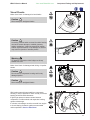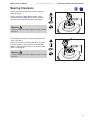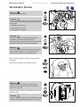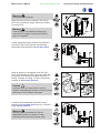
1
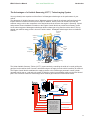
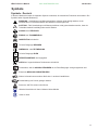
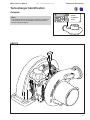
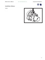
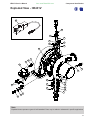
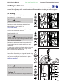
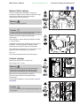
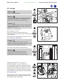
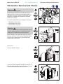
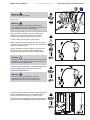
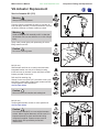
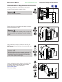
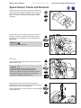
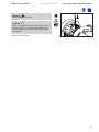
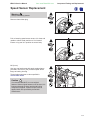
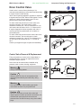
provided by:
DIESELUSAGROUP®
more info available at: www.DieselUSA.com
Holset HE431V
Service Repair Manual
Copyright 2007, Cummins Turbo Technologies Ltd. All rights reserved.
VGT, Command Valve and Super MWE are trade marks of Cummins Turbo Technologies Ltd.
Holset and the Holset Logo are registered trade marks of Cummins Turbo Technologies Ltd.
Cummins and the Cummins logo are registered trade marks of Cummins Inc.
HE431V Service Manual
from: www.DieselUSA.com
Foreword
Foreword
This publication was written to assist with turbocharger installation, maintenance and overhaul.
The specifications and procedures in this manual are based on information in effect at the time of publication.
Holset Service reserves the right to make any changes at any time without obligation. If differences are found
between your turbocharger and the information in this manual, contact your local Holset approved agent.
The latest technology and the highest quality standards are used in the manufacture of Holset Turbochargers.
When replacement parts are needed, we recommend using only genuine Holset parts.
HE431V Service Manual
from: www.DieselUSA.com
Table of Contents
Table of Contents
1: Introduction
About the Manual . . . . . . . . . . . . . . . . . . . . . . . . . . . . . . . . . . . . . . . . . . . . . . . . . . . . 1:1
How to Use the Manual. . . . . . . . . . . . . . . . . . . . . . . . . . . . . . . . . . . . . . . . . . . . . . . . 1:1
How to Order Holset Original Parts. . . . . . . . . . . . . . . . . . . . . . . . . . . . . . . . . . . . . . . 1:1
Description and Operation of Turbocharger . . . . . . . . . . . . . . . . . . . . . . . . . . . . . 1:2
General Information . . . . . . . . . . . . . . . . . . . . . . . . . . . . . . . . . . . . . . . . . . . . . 1:2
Introduction to Variable Geometry Turbochargers . . . . . . . . . . . . . . . . . . . . . . 1:2
Notes, Cautions and Warnings . . . . . . . . . . . . . . . . . . . . . . . . . . . . . . . . . . . . . 1:4
Installation Data . . . . . . . . . . . . . . . . . . . . . . . . . . . . . . . . . . . . . . . . . . . . . . . . . . . . 1:6
Installation Checklist . . . . . . . . . . . . . . . . . . . . . . . . . . . . . . . . . . . . . . . . . . . . . . . . 1:7
Symbols . . . . . . . . . . . . . . . . . . . . . . . . . . . . . . . . . . . . . . . . . . . . . . . . . . . . . . . . . . . 1:8
2: Component Identification
Turbocharger Identification . . . . . . . . . . . . . . . . . . . . . . . . . . . . . . . . . . . . . . . . . . . 2:1
Dataplate . . . . . . . . . . . . . . . . . . . . . . . . . . . . . . . . . . . . . . . . . . . . . . . . . . . . . . 2:1
Installation Options . . . . . . . . . . . . . . . . . . . . . . . . . . . . . . . . . . . . . . . . . . . . . . 2:2
Exploded View . . . . . . . . . . . . . . . . . . . . . . . . . . . . . . . . . . . . . . . . . . . . . . . . . . . . . . 2:3
Component List . . . . . . . . . . . . . . . . . . . . . . . . . . . . . . . . . . . . . . . . . . . . . . . . . . . . . 2:4
3: Troubleshooting and Diagnosis
Fault Finding Charts . . . . . . . . . . . . . . . . . . . . . . . . . . . . . . . . . . . . . . . . . . . . . . . . . 3:1
4: Component Testing and Replacement
Service Tools . . . . . . . . . . . . . . . . . . . . . . . . . . . . . . . . . . . . . . . . . . . . . . . . . . . . . . . 4:1
On Engine Checks . . . . . . . . . . . . . . . . . . . . . . . . . . . . . . . . . . . . . . . . . . . . . . . . . . 4:3
Bearing Clearance. . . . . . . . . . . . . . . . . . . . . . . . . . . . . . . . . . . . . . . . . . . . . . . . . . . 4:7
VG Actuator Checks . . . . . . . . . . . . . . . . . . . . . . . . . . . . . . . . . . . . . . . . . . . . . . . . . 4:8
VG Actuator Removal and Checks. . . . . . . . . . . . . . . . . . . . . . . . . . . . . . . . . . . . . 4:10
VG Actuator Replacement. . . . . . . . . . . . . . . . . . . . . . . . . . . . . . . . . . . . . . . . . . . . 4:12
VG Actuator Replacement Check . . . . . . . . . . . . . . . . . . . . . . . . . . . . . . . . . . . . . . 4:13
Speed Sensor Check and Removal . . . . . . . . . . . . . . . . . . . . . . . . . . . . . . . . . . . . 4:14
Speed Sensor Replacement . . . . . . . . . . . . . . . . . . . . . . . . . . . . . . . . . . . . . . . . . . 4:16
Dcon Control Valve . . . . . . . . . . . . . . . . . . . . . . . . . . . . . . . . . . . . . . . . . . . . . . . . . 4:17
Icon Control Valve . . . . . . . . . . . . . . . . . . . . . . . . . . . . . . . . . . . . . . . . . . . . . . . . . . 4:18
6: Service Data Sheets
VG Range Service Data Sheets . . . . . . . . . . . . . . . . . . . . . . . . . . . . . . . . . . . . . . . . 6:1
HE431V Service Manual
from: www.DieselUSA.com
Introduction
About the Manual
The procedures in this manual were developed to instruct in the correct overhaul of the designated Holset
turbochargers for optimum performance and minimum maintenance operation.
How to Use the Manual
The manual is split into sections designed to provide service information in a logical sequence. The manual
contains links to help the user navigate between relevant sections. Users who are unfamilier with navigating in
PDF documents are refered to Navigating in PDF documents in the Adobe® Acrobat® Reader™ help file.
Contents is an interactive page with links to all the sections. It can be accessed from any page
in the manual by clicking this icon.
Section 1 defines the layout of the manual, introduces the reader to the operation of the turbocharger
and presents important installation guidelines.
Sections 2, 3 and 4 concentrate on Turbocharger Component Identification, Troubleshooting and
Diagnosis, Component Testing and Replacement.
Section 5 identifies the Service and Overhaul procedures to be followed in the unlikley event of a
major turbocharger malfunction. (This section is not available for this turbocharger range at the
present time)
Section 6 quantifies build data to ensure the turbocharger will continue to operate to Holset Service
standard on completion of overhaul.
Manual sections 1 to 5 where applicable, appear as a self extracting compressed file which is organised
according to the steps needed to most easily and correctly maintain the operation of the turbocharger. Users
are required to download this file to hard disk. Section 6 has its own file identity and resides at
www.holset.co.uk. so that Holset can update the Service Data as changes occur. The links between manual
and service data are active only when the user is connected to the Internet.
Chapter 6 has an expiry date to encourage users to discard outdated saved or printed versions and always
access the latest information available at www.holset.co.uk.
When using the manual on-line this icon will link to Holset’s website to help find your nearest agent
for advice and how to order Holset original parts.
How to Order Holset Original Parts
To make sure of optimum performance, certain items must be discarded during disassembly and replaced with
new for re-assembly. These items are indicated in the Service and Overhaul section with the use of a
symbol.
All items showing a
are available in a basic overhaul kit.
*
*
To get the correct parts for your turbocharger, refer to the ‘component identification’ section of this manual to
help you find the following information:
1) Refer to the exploded view and component list to define the major components to be replaced.
2) Refer to the turbocharger’s dataplate which will be found on the compressor housing or actuator to
define the identifying information about your turbocharger build standard.
3) Contact your local Holset agent with componant identification nos. and dataplate assembly no., serial
no. and turbocharger type.
4) With this information, your local agent can provide you with the optimum kit of parts for re-assembling
your turbocharger for continued long life operation.
1:1
HE431V Service Manual
from: www.DieselUSA.com
Introduction
Description and Operation of Turbocharger
General Information
A turbocharger is a mechanical device which uses the engine’s exhaust gases to force more air into the engine
cylinders. Hot exhaust gas energy is used to turn a turbine wheel and shaft. At the other end of the shaft is the
compressor impeller (or compressor wheel), which draws in air and forces it into the engine cylinders.
Supplying increased air mass flow to the engine provides improved engine performance, lower exhaust smoke
density, improved operating economy and altitude compensation. The turbocharger has proven to be one of the
most beneficial devices for improving engine performance. It performs its job very well, as long as it is properly
cared for.
Introduction to Variable Geometry Turbochargers (VGT™)
The Need for Variable Geometry
The turbocharger on your vehicle’s engine is of a very advanced type, which varies the effective size of its
turbine in response to the driver’s demands. Under all conditions of driving, the turbine is electronically
controlled to change the amount of air supplied to the engine, to ensure maximum performance, lowest fuel
consumption and minimum exhaust emission levels.
When rapid vehicle acceleration is required, the turbocharger will produce air for the engine more quickly than
a conventional unit, thus eliminating turbocharger lag and giving improved vehicle drivability. As the engine and
turbocharger run in, and eventually start to wear, the combination of the variable turbine and its associated
electronic control, will change its characteristic to keep to the original performance and emission levels over a
wide range of ambient temperatures and altitude.
The Importance of Correctly Installing a Variable Geometry Turbocharger (VGT™)
The bearing housing of your turbocharger contains an internal water-cooled jacket. The purpose of this is to
reduce the operating temperature of the housing, to improve the operating environment of the speed sensor
and reduce the high soak temperatures produced when the engine is switched off after being heavily loaded.
The addition of water cooling has meant that there are two extra pipe connections to the turbocharger, to bring
water to the housing and to take it away. It is important to observe the correct installation of these pipes, so
that the circulation of the water is in the correct direction, or the effectiveness of the cooling system will be lost
and severe damage may result.
The Importance of Correct Operation of a Variable Geometry Turbocharger (VGT™)
A variable geometry turbocharger is controlled by the engine control module to optimise engine air fuel ratio for
performance and emissions. A malfunction may cause a mismatch between air and fuel supply which could
lead to progressive engine damage. It is important that any operating symptom which indicates incorrect
turbocharger operation is dealt with immediately by taking the unit safely out of service.
1:2
from: www.DieselUSA.com
HE431V Service Manual
Introduction
The Advantages of a Variable Geometry (VGT™) Turbocharging System
You may already have experience of the effect of a Wastegate turbocharger on the performance of your
vehicle.
The advantage of Variable Geometry over a Wastegate system is that all the exhaust gas flows through the
turbine wheel to increase net turbine power output. In addition, turbine power can be set to provide just
sufficient energy to drive the compressor at the desired boost level wherever the engine is operating. Speed
and pressure sensors feedback information to the Engine Control Module to provide the necessary control
As the name suggests a Wastegate turbocharger allows exhaust gas to by-pass the turbine wheel. This bypassed gas contains energy which is lost to the turbine wheel. Wastegate turbochargers have no feedback
controls.
Pneumatic
Control
Cylinder
Control Air
Exhaust Gas
Speed
Sensor
Fixed
Shroud
Plate
Air Inlet
Turbine
Compressor
Boost Air
Outlet
Operating
Yoke
Push Rods and Bushes
Sliding Nozzle Ring
and Vanes
The Holset Variable Geometry Turbine (VGT™) system works by controlling the width of a nozzle guiding the
gas flow into the turbine wheel. Control is achieved using an air supply from the vehicle’s auxiliary air reservoir.
The Engine Control Module modulates the supply pressure to the turbocharger pneumatic control cylinder
(actuator) which acts on a rod and yoke system to slide the nozzle ring and blades relative to the fixed shroud
plate. This movement varies the area through which exhaust gas enters the turbine wheel blades.
Pneumatic
Actuator
Control Air
Pressure
Sensor
(Optional)
Air Tank
Shut off
Valve
Control
Valve
Electrical
Control Line
Engine Speed
Engine Control Module (ECM)
Throttle Demand
Inlet Manifold
Pressure & Temperature
Exhaust Manifold Pressure
Fuel Injection Pump Information
Ambient Pressure & Temperature
Contains pre-set data on
airflow requirements for
any fuel quantity injected
at any engine speed,
with built-in safety
features for excessive
boost, smoke or
turbocharger speed.
Exhaust Outlet Pressure
Turbocharger Speed
1:3
HE431V Service Manual
from: www.DieselUSA.com
Introduction
Notes, Cautions and Warnings
Notes, Cautions and Warnings are used in this manual to emphasise important or critical instructions.
Note
Information which is essential to highlight.
Caution
Maintenance or Service procedures which if not strictly followed, will result in damage or destruction of the
turbocharger.
Warning
Maintenance or Service procedures which if not correctly followed will result in personal injury or loss of life.
Warning
The designated turbochargers weigh up to 22.5 kg (49 lb).
When lifting the turbocharger manually always get assistance to avoid back strain or dropping the unit and
consequential injury.
External parts include electrical wiring and connectors which are sensitive to handling. Some models are
fittedwith titanium compressor wheels which have sharp edges and should be handled with care.
Warning
Some parts are manufactured in fluoroelastomers (eg Viton) or similar that require special treatment in the case
of repair and service after fire.
Warning
Turbocharger surface temperature during operation can achieve 700°C (1300°F).
Caution
Orientation of the turbine housing of a variable geometry turbocharger is factory set. Any attempt to
re-orientate the housing can cause severe damage to the VG mechanism and may void warranty.
Caution
This variable geometry turbocharger has been factory balanced using the core balance process.
Service overhaul/repair must be carried out by Holset Engineering to ensure the variable geometry system is
correctly rebuilt. It is important to note that operating a turbocharger with rotor or core balance level greater
than design limits could cause turbocharger or engine failure.
Caution
In the event of a suspected variable geometry turbocharger malfunction, symptoms which may include low
power and black smoke, it is important to avoid potential progressive engine damage. The vehicle should be
taken out of service and towed to an appropriate repair facility as soon as this can be accomplished without
sacrificing the safety of the operator and/or passengers.
1:4
HE431V Service Manual
from: www.DieselUSA.com
Introduction
Notes, Cautions and Warnings
Note
Holset turbochargers can be remanufactured using recovered parts. Where it is necessary to dispose of
components or whole turbochargers, an environmentally responsible process such as recycling should be
used, with due regard to local laws.
Note
Holset Service receives many turbocharger returns that are no fault found. Before assuming the turbocharger
is not performing to specification always refer to the engine diagnostic system and the troubleshooting
diagnostic procedures of this manual.
1:5
HE431V Service Manual
from: www.DieselUSA.com
Introduction
Installation Data
1.
Holset Service receives many turbocharger returns that are no fault found. Before assuming the
turbocharger is not performing to specification always refer to the engine diagnostic system and the fault
finding chart of this manual to make all the recommended health checks.
2.
It is important that intake and exhaust systems are fitted in accordance with the recommendations of the
Equipment and Engine manufacturers. It is important not to overload the turbocharger by external
attachments or forces.
3.
The air filter must remove particles greater than 5 µm at an efficiency of 95%and be of sufficient capacity
to match the air consumption of the engine. Recommended filters should always be used with a pressure
drop indicator. Intake systems must be tightened to the values specified by the Equipment and Engine
manufacturers to withstand depressions up to 6.3 kPa (0.91 lbf/in2)
4.
Hose and clip connections of intake manifold systems must be capable of withstanding the turbocharger
pressure ratio. V-band clamps are preferred and must be used above 3:1 pressure ratio.
5.
Exhaust system connections must be tightened to the values specified by the Equipment and Engine
manufacturers to be capable of operating at exhaust back pressures of up to 10 kPa (1.5 lbf/in2).
Subject to an extensive review by Holset and formal approval, this limit may be increased to 25 kPa
(3.6 lbf/in2) if a catalytic convertor is fitted. Exhaust brake applications are permitted to operate at a
continuously rated pressure up to 450 kPa (65.3 lbf/in2) Holset has experience of instantaneous
pressures up to 700 kPa (101.5 lbf/in2) but any application operating above 450 kPa (65.3 lbf/in2) must be
referred to Holset for approval.
6.
Oil should be filtered to 10 µm with efficiency of 60% TWA (Time Weighted Average) /20 µm with
efficiency of 85% TWA. Efficiency assessed using ISO Standard 4572/SAE J 1858. Always use filters
recommended by the engine manufacturer.
7.
The oil quality must be as specified by the engine manufacturer and will be a minimum API - CD (MIL L - 2104C) specification. Improvement in life can be obtained by using super high performance diesel
(SHPD) oils, particularly where extended oil drain periods are used.
8.
Normal oil temperature is 95+/-5 °C (203+/-9 °F). It should not exceed 120 °C (248 °F) under any
operating condition.
9.
Any pre-lube oil must be clean and meet the minimum CD classification.
10. The orientation of turbine housing and bearing housing of a VG turbocharger is fixed. During installation,
do not attempt to rotate these components, as it may affect the operation of the VG actuating mechanism
and may void any warranty.
11. Holset permits oil drain pipes to decline at an overall angle of not less than 30 degrees below horizontal.
These turbochargers require a drain pipe of 19 mm internal diameter minimum which has integrated
connectors. To ensure oil drains into the engine under all operating conditions the return connection into
the engine sump must not be submerged.
12. Crankcase pressure should be limited to 0.8 kPa (0.12 lbf/in2). Pressure above this level should be
referred to Holset for further evaluation. Closed crankcase ventilation (CCV) systems are known to
operate at elevated pressure and all applications must be referred to Holset for approval.
13. Oil pressure must show at the turbocharger oil inlet within 3 - 4 seconds of engine firing to prevent
damage to turbocharger bearing system. A flexible supply pipe is recommended.
14. The minimum oil pressure when the engine is on load must be 210 kPa (30 lbf/in2). Normal maximum
operating pressure is 400 kPa (58 lbf/in2) although 600 kPa (88 lbf/in2) is permitted during cold start up.
Under idling conditions pressure should not fall below 70 kPa (10 lbf/in2).
15. Recommended oil flow ranges for these turbochargers are 2 - 3 litre/min at idle and 3.5 - 4.5 litre/min at
maximum engine speed.
16. Recommended coolant flows for these turbochargers are 3 litre/min at idle and 14 litre/min at maximum
engine speed. Coolant hose design must permit flow to increase progressively with engine speed.
17. Do not use liquid gasket substances or thread sealant as any excess can enter the turbocharger oil and
coolant systems to obstruct flow.
Note:
100 kPa = 1 bar (14.5037 lbf/in2 = psi).
1:6
HE431V Service Manual
from: www.DieselUSA.com
Introduction
Installation Checklist
1. Always understand why the original turbocharger needs replacing before fitting another unit.
2. Check the turbocharger dataplate to ensure the Part No. is correct for the engine/application.
3. Check the engine exhaust, intake and aftercooler systems are clean and without obstruction i.e. free from
oil, gasket pieces, dust/dirt/carbon or foreign objects.
4. Replace the oil and air filters using replacement parts specified by the equipment manufacturer.
5. Change the engine oil using the type specified by the engine manufacturer.
6. Check that the turbocharger oil inlet and drain pipes and connectors are clean, free from obstruction and
will not leak under pressure. Before re-installing flexible pipes always ensure any burnt-on lacquer or other
adhered material is removed from internal bores. If in doubt, always fit new pipes.
7. Check that the coolant pipes of water cooled bearing housing applications and connectors are clean, free
from obstruction and will not leak under pressure.
8. To pre-lube the turbocharger bearings, pour some clean engine oil into the oil inlet and rotate the
turbocharger rotor assembly by hand.
9. Check that the exhaust manifold flange is flat and undamaged. Mount the turbocharger on the flange and
check that the turbine inlet gasket fits properly without obstructing the gas passages.
10. Assemble the air intake and boost outlet connections. Check that the connections are secure and will not
leak in use.
11. Check the exhaust system is fitted using the original mounting arrangement provided by the equipment
manufacturer. Always re-fit any supports/brackets back in position to ensure the system is correctly
supported.
12. Assemble the exhaust system to the turbine housing outlet. Check that the gasket/connection is secure
and will not leak in use.
13. Assemble any coolant pipes and check that the connections are secure, without obstruction and will not
leak in use.
14. Assemble the turbocharger oil inlet pipe and check that the connection is clean, secure and will not leak in
use.
15. Check all clamps and fasteners are correctly tightened to the torque recommended by the equipment
manufacturer.
16. Make the electrical connections between VG sensors and engine control module (ECM). Check the
electrical connection between control valve and ECM.
17. Check the air connection between the vehicle auxiliary tank and control valve.
18. Connect the air pipe from the control valve to the actuator ensuring the pipe bore is clean and dry before
fitment.
19. Make any ECM checks recommended by the engine manufacturer.
20. Crank the engine WITHOUT firing until engine oil flows out of the turbocharger drain flange.
21. Assemble the oil drain pipe and check that the connection is secure, without obstruction and will not leak in
use.
22. Start the engine and run at idle speed for approximately 1 minute so that the oil supply system is fully
operational.
23. Accelerate the engine and check that there are no leaks/obstructions of air/oil/coolant/gas under pressure.
24. Check that no hose or connection deforms under normal operation.
25. Before switching off the engine, leave it running at idle speed for at least 1 minute to cool the turbine.
1:7
HE431V Service Manual
from: www.DieselUSA.com
Introduction
Symbols
Symbole - Deutsch
In diesem Handbuch werden die folgenden Symbole verwendet, die wesentliche Funktionen hervorheben. Die
Symbole haben folgende Bedeutung:
WARNUNG - Unterhaltungs und Wartungsverfahren müssen genau befolgt werden, da ein
Nichtbeachten zu Personenschäden oder tödlichen Verletzungen führt.
ACHTUNG - Falls Unterhaltungs und Wartungsverfahren nicht genau beachtet werden, kann der
Turbolader dadurch beschädigt oder zerstört werden.
AUSBAU bzw. ZERLEGEN.
EINBAU bzw. ZUSAMMENBAU.
INSRPEKTION erforderlich.
Teil oder Baugruppe REINIGEN.
DIMENSION - oder ZEITMESSUNG.
Teil oder Baugruppe ÖLEN.
WERKZEUGGRÖSSE wird angegeben.
ANZUG auf vorgeschriebenes Drehmoment erforderlich.
Sicherstellen, daß die AUSWUCHTMARKEN an der Rotor-Baugruppe richtig ausgerichtet sind.
Elektrische MESSUNG DURCHFÜRHREN.
Weitere Informationen an anderer Stelle bzw. in anderen Handbüchern.
Schutzkleidung muß immer getragen werden.
KG
Deutet an, daß Teile schwer sein können.
Website-Verzeichnis mit Ihrem nächsten Holset-Händler.
Gehe zu Inhalt
1:8
HE431V Service Manual
from: www.DieselUSA.com
Introduction
Symbols - English
The following group of symbols have been used in this manual to help communicate the intent of the
instructions. When one of the symbols appears, it conveys the meaning defined below.
WARNING - Serious personal injury or extensive property damage can result if the warning
instructions are not followed.
CAUTION - Minor personal injury can result or a part, an assembly or the engine can be damaged if
the caution instructions are not followed.
Indicates a REMOVAL or DISASSEMBLY step.
Indicates an INSTALLATION or ASSEMBLY step.
INSPECTION is required.
CLEAN the part or assembly.
PERFORM a mechanical or time MEASUREMENT.
LUBRICATE the part or assembly.
Indicates that a WRENCH or TOOL SIZE will be given.
TIGHTEN to a specific torque.
Ensure that the BALANCE MARKS on the rotor assembly are in alignment
PERFORM an electrical MEASUREMENT.
Refer to another location in this manual or another publication for additional information.
Please wear protective clothing at all times.
KG
Indicates components may be heavy.
Website access to find your nearest Holset Agent.
Go to contents
1:9
HE431V Service Manual
from: www.DieselUSA.com
Introduction
Simbolos - Español
Los simbolos siguientes son usados en estes manual para clarificar el proceso de las instrucciones. Cuado
aparece uno de estos simbolos, su significado se espcifica en la parte inferior.
ADVERTENCIA – Procedimientos de Mantenimiento o Servicio que al no seguirse resultarán en
daños personales o pérdida de vida.
ATENCION – Procedimientos de Mantenimiento o Servicio que al no seguirse al pie de la letra,
resultarán en el daño o la destrucción del turbosobrealimentador.
Indica un paso de REMOCION o DESMONTAJE.
Indica un paso de INSTALACION o MONTAJE.
Se requiere INSPECCION.
LIMPIESE la pieza o el montaje.
Ejecutese una MEDICION mec·nica o del tiempo.
LUBRIQUESE la pieza o el montaje.
Indica que se dar· una LLAVE DE TUERCAS o el TAMA—O DE HERRAMIENTA.
APRIETESE hasta un par torsor especifico.
Ceriórese de que est·n alineadas las marcas de balance en el rotor.
EJECUTESE una MEDICION eléctrica.
Para información adicional refiérase a otro emplazamiento de este manual o a otra publicación
anterior.
Favor de siempre llevar ropa protectora.
KG
Indica que los componentes pueden ser pesados.
Acceso a Sitio Web para localizar su agente Holset más cercano.
Ir a la tabla de materias
1:10
HE431V Service Manual
from: www.DieselUSA.com
Introduction
Symboles - Français
Les symboles suivants sont utilisés dans ce manuel pour aider à communiquer le but des instructions. Quand
l’un de ces symboles apparait, il évoque le sens défini ci-dessous:
ATTENTION DANGER - Procédures de maintenance ou d’entretien qui, si elles ne pas observées
correctement, auront pour résultat des lésions corporelles ou un décès.
MISE EN GARDE - Procédures de maintenance ou d’entretien qui, si elles ne sont pas observées
strictement, auront pour résultat de causer des dégâts au turbocompresseur ou de conduire à sa
destruction.
Indique une opération de DEPOSE.
Indique une opération de MONTAGE.
L’INSPECTION est nécessaire.
NETTOYER la pièce ou l’ensemble.
EFFECTUER une MESURE mécanique ou de temps.
GRAISSER la pièce ou l’ensemble.
Indique qu’une DIMENSION DE CLE ou D’OUTIL sera donnée.
SERRER à un couple spécifique.
S’assurer que les repères d’équilibrage sur l’ensemble de rotor sont alignés.
EFFECTUER une MEASURE électrique.
Se reporter à un autre endroit dans ce manuel ou à une autre publication pour obtenir des
information plus complètes.
Il faut toujours mettre vêtements de protection.
KG
Indique que les composants peuvent être lourds.
Accès au site Web pour trouver l’agent Holset le plus proche.
Aller au sommaire
1:11
HE431V Service Manual
from: www.DieselUSA.com
Introduction
Símbolos - Português
Os símbolos a seguir serão utilizados neste manual para facilitar a comunicação das instruções e seue
significados estão déscritos abaixo.
ATENÇÃO - Os procedimentos de Manutenção ou Serviços que não forem seguidos correctamente
resultarão em ferimentos pessoais ou riscos de vida.
AVISO - Os procedimentos de Manutenção ou Serviço que não forem rigorosamente seguidos
resultarão em danos ou destruição do carregador turbo.
Indica um passe de DESMONTAGEM.
Indica um passo de MONTAGEM.
Requer inspeção.
LIMPE a peça ou conjunto.
Requer Medição mecãnica ou de tempo.
LUBRIFIQUE a peça ou o conjunto.
Indica necessidade de APERTO.
TORQUEAR de acordo com o especificado.
Assegure-se de que as MARCAS DE BALANCEAMENTO do conjunto eixorotor estejam alinhadas.
Requer medição ELÉTRICA.
Procure em outra seção deste manual ou em publicação par obter informações adicionais
Por favor, sempre utilize EPI (Equipamento de Protecao Individual)
KG
Indica que os componentes podem estar pesados.
Visite o Website para encontrar o seu Agente Holset mais perto.
Vá para Conteúdo
1:12
HE431V Service Manual
from: www.DieselUSA.com
Component Identification
Turbocharger Identification
Dataplate
Note
The dataplate will be fitted to the compressor housing (8).
The information from the dataplate must be quoted for
service and parts support.
35XXXXX
XYYMMXXXXX
HE431V
HE431V
2:1
HE431V Service Manual
from: www.DieselUSA.com
Component Identification
Installation Options
Type A
2:2
from: www.DieselUSA.com
HE431V Service Manual
Component Identification
Exploded View - HE431V
125
120
112
115
27
105
156
115
92
159
27
27
126
158
27
27
114
103
113
106
114
115
105
115
53
77
129
106
Note
Exploded views represent a generic build standard. Parts may be added or subtracted in specific applications.
2:3
HE431V Service Manual
from: www.DieselUSA.com
Component Identification
Component List - HE431V
Item No.
Description
121
VG Actuator Kit comprising:
Quantity
1
126
VG Actuator fitted with:
1
159
Adapter, Air Inlet fitted with:
1
27
O-Ring Seal
2
122
VG Actuator Fittings Kit comprising:
1
92
Roll Pin
1
106
Screw, Actuator
3
77
Retaining Ring, End Link
1
129
Sacrificial Anode
1
123
VG Bearing Housing Seals & Adapter Kit (Water & Oil) comprising:
1
53
Gasket, Oil Outlet
1
113
Adapter, Oil Inlet fitted with:
1
114
O-Ring Seal, Oil Inlet
2
105
Connector Male, Water fitted with:
2
115
O-Ring Seal, Water
4
124
Speed Sensor Kit comprising:
1
112
Speed Sensor
1
120
Cap Head Screw
1
27
O-Ring Seal
1
144
Control Valve
1
156
Bolt
1
158
Temperature Sensor fitted with:
1
27
103
27
O-Ring Seal
Pressure Plug fitted with:
O-Ring Seal
1
1
1
Note
Exploded views may not contain all listed components.
2:4
HE431V Service Manual
from: www.DieselUSA.com
Troubleshooting and Diagnosis
Oil Leak from Turbine Seal
Oil Leak from Compressor Seal
Cyclic Sound from the Turbocharger
Turbocharger Noisy
High Oil Consumption
Blue Exhaust Smoke
Black Exhaust Smoke
Engine Lacks Power
Smoke
Poor Transient Response
Engine Running Hot
Fault Finding Chart - All Applications
Dirty air cleaner
Clean or replace element according to manufacturer’s recommendations
Restricted compressor intake duct
Remove restriction or replace damaged parts as required
Restricted air duct from compressor to intake manifold
Remove restriction or replace damaged parts as required
Restricted intake manifold
Refer to engine manufacturer’s manual and remove restriction
Air leak in feed from air cleaner to compressor
Replace seals, gaskets or tighten fasteners as required
Air leak in feed from compressor to intake manifold
Replace seals, gaskets or tighten fasteners as required
Air leak between intake manifold and engine
Refer to engine manufacturer’s manual and replace gaskets or tighten fasteners as required
Foreign object in exhaust manifold (from engine)
Refer to engine manufacturer’s manual and remove obstruction
Restricted exhaust system
Remove restriction or replace damaged parts as required
Exhaust manifold cracked, gaskets blown or missing
Refer to engine manufacturer’s manual and replace gaskets or damaged parts as required
Gas leak at turbine inlet/exhaust manifold joint
Replace gasket or tighten fasteners as required
Gas leak in ducting after turbine outlet
Refer to engine manufacturer’s manual and repair leak
Restricted turbocharger oil drain line
Remove restriction or replace damaged parts as required
Restricted engine crankcase breather
Refer to engine manufacturer’s manual, clear restriction
Turbocharger bearing housing sludged or coked
Change engine oil and oil filter, overhaul or replace turbocharger as required
Fuel injection pump or fuel injectors incorrectly set
Refer to engine manufacturer’s manual and replace or adjust faulty components as required
Engine valve timing incorrect
Refer to engine manufacturer’s manual for correct settings and adjust as required
Worn engine piston rings or liners
Refer to engine manufacturer’s manual and repair as required
Burnt valves and/or pistons
Refer to engine manufacturer’s manual and repair as required
Excessive dirt build up on compressor wheel and/or diffuser vanes
Contact your local approved dealer
Turbocharger damaged
Find and correct cause of failure, or replace turbocharger as necessary
3:1
HE431V Service Manual
from: www.DieselUSA.com
Troubleshooting and Diagnosis
Oil leak
Coolant leak
Reduced braking
Poor acceleration
Turbocharger noisy
Low power at low engine speed
Engine does not run smoothly
Intermittent low power
Intermittent engine braking
Engine Overheats
Engine Lacks Power
Fault Finding Chart - Variable Geometry Turbine
Actuator rod not moving
Check for air leaks and change clips and hoses as appropriate. If actuator works with
separate air supply, check control valve. If no actuator movement confirmed, replace
actuator. If no movement with new actuator replace turbocharger.
VG mechanism partially jammed
Refer to Engine Control Unit (ECU) diagnostics for posible fault code data. Check for air
leaks and change clips and hoses as appropriate. If air system OK, check actuator
movement. If full and free movement not confirmed, replace actuator. If partial movement
with new actuator replace turbocharger.
Actuator loose or damaged
Refer to ECU diagnostics for possible fault code data. Check for damage to actuator
bracket and fasteners. If mechanical installation is OK, check actuator movement. If full
and free movement not confirmed, replace actuator. If partial movement with new actuator
replace turbocharger
Actuator air feed lines or connectors leaking
Check for air leaks and change clamps and hoses as appropriate. If actuator air system
OK, refer to general turbocharger fault finding chart.
No speed signal
Check sensor connections. If pin resistance measurement is incorrect replace sensor.
Where sensor may have been overheated check ECU diagnostic fault codes and if
necessary replace sensor.
Intermittent or noisy speed signal
Check sensor with multimeter. If either resistance measurement is incorrect replace
sensor. Where sensor may have been overheated check ECU diagnostic fault codes and
if necessary replace sensor.
No control valve drive signal
To ensure drive signal is being received from ECU check control valve operation. If either
0 V or battery voltage condition is incorrect replace control valve and refer to engine
manual.
Intermittent control valve drive signal
Refer to ECU diagnostics for possible fault code data. Check control valve connection to
ECU. If control valve condition at either 0 V or vehicle battery voltage is incorrect or if
intermittent fault persists replace control valve whilst referring to engine manual.
No boost pressure signal (P2)
If the ECU diagnoses a boost pressure signal error refer to engine manual.
No air inlet temperature signal (T2)
If the ECU diagnoses an air inlet temperature signal error refer to engine manual.
Incorrect actuator pressure
If the VG system has an actuator pressure sensor which reads an incorrect actuator
pressure signal the fault is likely to be with the shut-off valve, control valve or pressure
sensor itself. Refer to engine manual for repair and replacement instructions for shut-off
valve and pressure sensor test and replacement. Check and replace control valve whilst
referring to engine manual.
Incorrect control valve supply pressure
Likely causes are malfunctions of shut-off valve or control valve. Refer to engine manual
for repair and replacement instructions for shut-off valve. Check and replace control valve
whilst referring to engine manual.
Control valve sticking
Check actuator pressure if sensor fitted. If control valve sticking is likely cause, spray light
penetrating oil into control valve inlet. Allow to lubricate the valve mechanical parts.
Conduct pressure check. If either 0 V or battery voltage condition is incorrect change
valve whilst referring to engine manual.
3:2
HE431V Service Manual
from: www.DieselUSA.com
Troubleshooting and Diagnosis
Oil leak
Coolant leak
Reduced braking
Poor acceleration
Turbocharger noisy
Low power at low engine speed
Engine does not run smoothly
Intermittent low power
Intermittent engine braking
Engine Overheats
Engine Lacks Power
Fault Finding Chart - Variable Geometry Turbine Continued
Coolant flow restricted
Check coolant pipework and connections for damage. Replace damaged bearing housing
fittings using only Holset recommended parts. Refer to engine manual for flow data and
service instructions for all other connections and pipework.
Coolant pipework or connectors leaking
Check coolant pipework and connectors for leakage. Tighten connections and if leak
persists, replace failed connectors or pipes using Holset recommended parts.
Oil feed and return lines or adaptors leaking
Check oil feed and return pipes and adaptors for leakage. Check O-ring seals and replace
if necessary. Tighten adaptors and if leak persists, replace failed adaptors or pipes using
Holset recommended parts.
Oil leakage from speed sensor
Check O-ring seal and replace if necessary. Refit sensor and if leak persists replace
speed sensor.
Bearing housing damaged
If O-ring or connector replacement does not resolve an oil leak, the bearing housing
tappings may be damaged requiring replacement of the turbocharger. Where water
connector replacement does not resolve a water leak, the bearing housing tappings may
be damaged requiring replacement of the turbocharger.
3:3
HE431V Service Manual
from: www.DieselUSA.com
Component Testing and Replacement
Service Tools
The following special tools are recommended to perform procedures in this manual. The use of these tools is
shown in the appropriate procedure.
Part No.
Tool Description
Tool Illustration
Torque Wrench
Regulated Air Supply
Steel Rule
13 mm Diameter Clean Rubber Plug
0-1000 kPa (150 lbf/in2) Pressure Gauge
Dial Gauge and Dial Gauge Adapter
-0+
10
10
TYPE 20
20
20
30
30
MERCER
40
40
50
Allen Key (6 mm A/F)
Caution
All Service and Maintenance settings are shown in Holset’s Service Data Sheet. It is essential that these
settings are used. Common tools found in mechanic’s tool box not included.
4:1
HE431V Service Manual
from: www.DieselUSA.com
Component Testing and Replacement
Service Tools
The following special tools are recommended to perform procedures in this manual. The use of these tools is
shown in the appropriate procedure. These tools can be purchased from your local Authorised Repair Location.
Part No.
Tool Description
Tool Illustration
Vehicle Battery Supply
Multi-meter
Caution
All Service and Maintenance settings are shown in Holset’s Service Data Sheet. It is essential that these
settings are used. Common tools found in mechanic’s tool box not included.
4:2
HE431V Service Manual
from: www.DieselUSA.com
Component Testing and Replacement
On Engine Checks
Variable geometry turbochargers have potential oil, gas, coolant and air leak paths. They are fitted with
sensors and an actuator which contain sensitive components. When checking and correcting leaks it
is essential that good practice and the correct tools are used to avoid damaging the turbocharger.
Oil Leakage
Bearing Housing M14 x 1.5 (19 mm)
Pipe Fitting 11/16 - 16 UN 2A
Warning
Always wear safety glasses.
Replacement seals and adapters should be fitted
without sealant as this can contaminate the oil. Torque
tighten adapter to value specified in
Service Data Sheet.
It is important to avoid kinked or worn pipes during
servicing and subsequent operation.
Flange fitting M8 x 1.25
Warning
Inlet oil is pressurized and outlet oil is hot. Never take
service action with engine running. Protect face and
hands from hot fluid leakage.
Replacement gaskets and flange fasteners should be
fitted without sealant as this can contaminate the oil.
Torque tighten fasteners to value specified by engine
manufacturer.
All outlet pipes should be free flowing without kinks and
sharp bends and decline at an overall angle not less
than 30 degrees below the horizontal.
M6 x 1.0 (8 mm)
Speed sensor is sealed by an o-ring and fastened using
a dry setscrew with patch sealant feature. Always use
new setscrew provided in Holset Service Kit when refitting sensor. Torque tighten sensor to value specified
in Service Data Sheet.
Caution
Do not use sealant when fitting speed sensor as this
may contaminate oil and bearings.
Caution
If leak occurs at actuation lever change turbocharger.
4:3
HE431V Service Manual
from: www.DieselUSA.com
Component Testing and Replacement
Exhaust Gas Leakage
Turbine housing flange leakage will cause soot
formation on flange. Check exhaust manifold to flange
seal ensuring fastener torque meets engine
manufacturer’s recommendation.
Warning
Always wear safety glasses.
Caution
Turbine housings can exhibit cracking when subject to
excessive thermal and mechanical loads.
Cracking of inlet duct requires turbocharger
replacement.
Check flange for cracks and ensure flatness is within
0.1 mm (0.004 in).
Acceptance and rejection guidelines are shown in this
illustration. If exhaust gasket is available, always
ensure that any cracks lie within its sealing area
Check fastener hole diameter is not more than 1.5 mm
larger than max. thread diameter of fastener.
M10 X 1.5
Check flange threaded holes with thread gauge.
Coolant Leakage
Bearing Housing M18 x 1.5 (19/24 mm)
Pipe Fitting 13/16 - 16 UN
Warning
Water connections may be hot and pressurized.
Never take service action with engine running.
Protect face and hands from hot fluid leakage.
Repair leaks by refitting/replacing adapters.
Where housing threads are damaged replace
turbocharger.
Torque tighten adapters to value specified in Service
Data Sheet.
Caution
Do not use sealant as this may affect performance of
o-ring seals.
4:4
HE431V Service Manual
from: www.DieselUSA.com
Component Testing and Replacement
Air Leakage
Warning
Always wear safety glasses.
Warning
Pneumatic connections may be pressurised. Always
ensure engine keyswitch is in off-position before
taking service action and use face protection.
Caution
Visual checks and audible checks for air leaks may be
completed safely with running engine. Alternatively,
apply external air source.
Actuator 7/16 - 20 UNF (5/8 in)
Pipe Fitting 9/16 - 18 UNF
Check for air leaks at end plates and air hose
connectors ensuring torque meets engine manufacturer’s
recommendation.
When replacing air inlet adapter torque tighten to value
specified in Service Data Sheet.
Caution
If actuator leaks air, however little, it must be
replaced. Using damaged actuator will result in inferior
performance of turbocharger and engine.
Check for air leak at base of actuator housing.
Warning
Actuator is not a serviceable item. Do not
disassemble actuator as release of in-built
separating forces may cause personal injury.
Temperature Sensor M14 x 1.5 (13/16 in)
Pressure Plug M14 x 1.5 (6 mm - Allen Key)
Air leakage passed sensor and/or pressure plug can
lead to unfiltered air ingress to compressor. It may be
possible to detect leakage from evidence of dirt lines in
sensor/plug bores or on visible compressor housing
internal surfaces. Torque fasteners to value specified in
Service Data Sheet.
Where leakage continues replace temperature sensor
and/or pressure plug. If compressor housing threads
are damaged, replace turbocharger.
4:5
HE431V Service Manual
from: www.DieselUSA.com
Component Testing and Replacement
Visual Checks
Make visual check for damaged or bent blades.
Caution
Never attempt to straighten blades.
Caution
Loosening, rotation and/or removal of turbine housing
can cause severe damage to variable geometry
turbine mechanism. V-band is protected by tamper
evident clip and evidence of clip damage or removal
may result in rejection of warranty claims.
Warning
VTi titanium compressor wheel edges are sharp.
Handle with care.
Make visual check for damaged and fouling of impeller
blades.
Caution
Do not remove compressor housing as this may
damage impeller.
Caution
Never attempt to straighten blades.
With intake system disconnected from compressor
housing, it may be possible to check visually for excess
bearing axial and radial clearances.
If light finger pressure causes contact between
compressor or turbine wheel and respective housing
replace turbocharger.
If in doubt, turbocharger must be removed from engine
to check bearing clearance against recommended
values specified in Service Data Sheet.
4:6
HE431V Service Manual
from: www.DieselUSA.com
Component Testing and Replacement
Bearing Clearance
Secure turbine housing and check thrust clearance
using dial gauge.
-0+
10
10
Ensure clearance is within MIN and MAX values
specified in Service Data Sheet. If axial clearance
does not meet specification replace turbocharger.
TYPE 20
20
20
30
30
MERCER
40
40
50
Warning
Titanium compressor wheel edges are sharp. Handle
with care.
Check radial movement at compressor impeller nose
using a dial gauge.
Ensure movement is within MIN and MAX TIR (Total
Indicator Reading) values specified in Service Data
Sheet. If radial movement does not meet specification
replace turbocharger.
Warning
Titanium compressor wheel edges are sharp. Handle
with care.
4:7
HE431V Service Manual
from: www.DieselUSA.com
Component Testing and Replacement
VG Actuator Checks
Warning
Always wear safety glasses.
Caution
Actuator movement and leak checks should be carried
out on engine. If turbocharger removal is necessary it
will require:
• Drainage of water system
• Disassembly of oil circuit
• Disconnection of sensors
Caution
During VG actuator checks and replacement it is
necessary to break pneumatic connection
between control valve and actuator. It is essential that
open pipe is protected from dirt and fluid entry.
Warning
Pneumatic connections may be pressurised. Always
ensure engine keyswitch is in off-position before
taking service action and use face protection.
Refer to engine manual for details of hose threaded
connection.
Remove hose connector from actuator air inlet.
Warning
Avoid touching VG mechanism as finger injury
may result from sudden movement of assembly
when air is supplied.
Connect and secure hose from regulated air supply to
actuator air inlet.
Caution
Ensure regulated air supply is dry and filtered to avoid
damage to actuator piston and actuator o-ring seals.
4:8
HE431V Service Manual
from: www.DieselUSA.com
Component Testing and Replacement
Warning
Always wear safety glasses.
Apply 300 kPa (43.5 lbf/in2) maximum 450 kPa (65
lbf/in2) from regulated air supply and ensure actuator
rod moves lever.
Warning
Avoid touching VG mechanism as finger injury
may result from sudden movement of assembly
when air is supplied.
Control regulated air supply between 0 and 300 kPa
(43.5 lbf/in2) and confirm actuator travel is within
permissible range specified in Service Data Sheet.
Whilst air pressure is still applied at 300 kPa (43.5
lbf/in2) check actuator for leaks. Use soapy water and
small brush. Small bubbles will appear if actuator is
leaking. If actuator is leaking, it must be removed by
reference to VG Actuator Removal.
Caution
If actuator leaks air, however little, it must be
replaced. Using damaged actuator will result in inferior
performance of turbocharger and engine.
If actuator travel is not within permissible range
specified in Service Data Sheet remove by reference
to VG Actuator Removal.
Warning
Actuator is not a serviceable item. Do not
disassemble actuator as release of in-built
separating forces may cause personal injury.
4:9
HE431V Service Manual
from: www.DieselUSA.com
Component Testing and Replacement
VG Actuator Removal and Checks
Warning
Always wear safety glasses.
Where actuator movement is outside the range or
where actuator air leaks have been discovered it is
necessary to remove actuator to continue with fault
diagnosis. If possible these procedures should be
carried out on engine.
If removal of turbocharger is necessary it will require:
• Drainage of water system
• Disassembly of oil circuit
• Disconnection of sensors
Warning
Pneumatic connections may be pressurised. Always
ensure engine keyswitch is in off-position before
taking service action and use face protection.
Where road spray, dirt and fluid ingress has caused
fouling or corrosion of the actuator integrated bracket
fasteners apply penetrating oil in accordance with
manufacturer’s instructions.
M8 (10 mm)
Loosen 2 actuator screws.
Connect clean dry regulated air supply to actuator air
inlet and apply 200 kPa (29 lbf/in2) pressure to release
actuator pre-load between bracket and lever.
4:10
HE431V Service Manual
from: www.DieselUSA.com
Component Testing and Replacement
Warning
Always wear safety glasses.
M8 (10 mm)
Warning
Rod may retract quickly when freed from pivot
arm. Avoid touching the VG assembly until rod is at
rest and there is no risk of finger injury.
Remove and discard screw and cover plate/zinc washer
from crank journal. Remove end link retaining ring.
Slide actuator rod off the crank journal. Remove
actuator screws and discard. Remove actuator.
If crank journal is worn replace turbocharger.
Refer to engine manual for details of hose - threaded
connector. Connect and secure hose from regulated air
supply to actuator air inlet.
Control regulated air supply between 0 and 300 kPa
(43.5 lbf/in2) and confirm actuator travel is within
permissible range specified in Service Data Sheet.
Caution
Detached actuator stroke is greater than stroke when
attached to VG mechanism. Ensure correct range is
read from Service Data Sheet.
If actuator travel is not within permissible range shown
in Service Data Sheet replace by reference to
VG Actuator Replacement.
Warning
Actuator is not a serviceable item. Do not
disassemble actuator as release of in-built
separating forces may cause personal injury.
If actuator travel is within permissible range specified in
Service Data Sheet use mole (vice) grips and light
force to check linear travel of VG crank journal.
If pin does not travel smoothly within permissible range
specified in Service Data Sheet replace turbocharger.
4:11
HE431V Service Manual
from: www.DieselUSA.com
Component Testing and Replacement
VG Actuator Replacement
Service Actuator Kit (121)
Warning
Always wear safety glasses.
Connect clean dry regulated air supply to actuator air
inlet and apply 100 kPa (14.5 lbf/in2) maximum 150 kPa
(22 lbf/in2) pressure to release actuator pre-load.
Warning
Avoid touching the VG assembly until it is clear that
the actuator rod is at rest and there is no risk of finger
injury.
Spray crank journal lightly with penetrating oil before
fitting actuator end link.
Caution
Do not use Lithium grease.
M8 (10 mm)
Slide actuator end link on to crank journal and ease
integrated bracket onto roll pin in bearing housing.
Insert two new dry actuator screws with patch sealant
feature provided in service kit.
Refit end link retaining ring.
Always fit new cover plate (157) and short screw (120)
so that the cupped edge wraps round actuator end link.
Torque tighten to value specified in
Service Data Sheet.
Caution
Never refit thick zinc washer and existing bolt.
M8 (10 mm)
Torque tighten actuator screws to value specified in
Service Data Sheet.
Caution
It is recommended NOT to re-use original actuator
screws. Where original fasteners must be used, it is
important threads are clean and thread locking
compound is applied. Fastener torque must be
applied within time specified by thread lock
manufacturer.
4:12
HE431V Service Manual
from: www.DieselUSA.com
Component Testing and Replacement
VG Actuator Replacement Check
Following installation it is necessary to check that
actuator moves through complete stroke.
Warning
Always wear safety glasses.
Ensure hose from dry regulated air supply is properly
secured to actuator air inlet.
Warning
Avoid touching the VG assembly until it is clear that
actuator rod is at rest and there is no risk of finger
injury.
Apply 300 kPa (43.5 lbf/in2) maximum 450 kPa (65
lbf/in2) air pressure until actuator is moving freely over
whole stroke.
Caution
Where progressive motion cannot be achieved it is
probable that an element of variable geometry
mechanism internal to turbocharger is damaged.
In this case replace turbocharger.
Control regulated air supply between 0 and 300 kPa
(43.5 lbf/in2) and confirm actuator travel is within
permissible range to value specified in
Service Data Sheet.
Remove air supply.
4:13
HE431V Service Manual
from: www.DieselUSA.com
Component Testing and Replacement
Speed Sensor Check and Removal
Disconnect sensor at electrical connector. Using multimeter, check the resistance between pins 1 and 2 is in
range 200 to 2000 Ohm with sensor at 20°C. Check
pins 1 to 3 and 2 to 3 have very high (min 1 MOhm)
resistance.
1
2
3
Where road spray, dirt and fluid ingress has caused
fouling or corrosion of speed sensor fastener apply
penetrating oil in accordance with oil manufacturer’s
instructions.
Warning
Always wear safety glasses.
M6 (8 mm)
Using socket wrench and ratchet, loosen and remove
speed sensor screw.
Caution
Breaking sealed fastener joint may require
significant torque. It is essential that socket
spanner is properly engaged on fastener to avoid
inadvertent damage to speed sensor cable and
connector resulting from spanner slip.
Extract speed sensor ensuring that o-ring seal is
removed with sensor. This is conveniently achieved by
tilting sensor as it exits recessed bore.
Place speed sensor on clean surface to avoid collection
of metal particles.
4:14
HE431V Service Manual
from: www.DieselUSA.com
Component Testing and Replacement
Warning
Always wear safety glasses.
Caution
Removal of speed sensor leaves an open access to
bearing housing. It is essential that no dirt or fluids
enter bearing housing cavity during speed sensor
replacement.
Insert clean rubber plug.
4:15
HE431V Service Manual
from: www.DieselUSA.com
Component Testing and Replacement
Speed Sensor Replacement
Warning
Always wear safety glasses.
Remove clean rubber plug.
Prior to inserting speed sensor ensure it is clean and
unable to collect metal particles as it is inserted.
Ensure o-ring seal is in position on sensor body.
M6 (8 mm)
Use new cap head screw with patch sealant feature
provided in service kit (124) to fasten speed sensor
flange to bearing housing.
Torque tighten setscrew to value specified in
Service Data Sheet.
Caution
It is recommended NOT to re-use original
fastener. Where original fastener must be used, it is
important threads are clean and thread locking
compound is applied. Fastener torque must be
applied within time specified by thread lock
manufacturer.
4:16
HE431V Service Manual
from: www.DieselUSA.com
Component Testing and Replacement
Dcon Control Valve
Control valve is remote from turbocharger. It is
connected pneumatically to VG actuator and electrically
to engine control module (ECM).
24 V - Control Valve
Valve controls pressure applied to actuator in response
to signals sent from ECM. Where ECM signals a control
valve error, check wiring harness is good. If error
persists check contol valve operation.
To check electrically, disconnect control valve at its
electrical connector. Use multi-meter to check
resistance between pins 1 and 2. Resistance for a 24
Volt control valve should be 24.5 +/- 0.5 Ohm at 20°C.
If engine diagnostics indicate a problem with valve it
must be serviced by replacement as it contains no
serviceable parts.
To check electrically, disconnect the control valve at its
electrical connector. Use a multi-meter to check
resistance between pins 1 and 2. The resistance for a
12 Volt control valve should be 6.5 +/- 0.5 Ohm at
20°C.
12 V - Control Valve
Contact your approved agent for parts and availability.
Control Valve Removal & Replacement
Fixing and position of control valve is dependant on
engine application. Process of replacement will be
included in engine manual.
Dcon valve can be cleaned when installed using
pressure wash or steam cleaning equipment.
Warning
Always wear safety glasses.
Control Valve
12 V or 24 V
Caution
Always ensure the valve is non-operational but
connected pneumatically and electrically during
cleaning.
Air Supply
Battery
12 V or 24 V
Depending on vehicle system.
Polarity not important
Warning
Care must be taken when breaking pneumatic
connections as these may be pressurised.
Caution
Where it is necessary to break inlet, outlet and
capsule pressure sensor pneumatic connections, it is
essential that open pipes and connectors are
protected from dirt and fluid entry using clean rubber
plugs.
4:17
HE431V Service Manual
from: www.DieselUSA.com
Component Testing and Replacement
Icon Control Valve
Valve Air and Electric Connections
Do not disconnect icon valve electrically or
pneumatically at this stage.
The Icon valve has three pneumatic ports:
Port 1
Air supply port: M12 x 1.5
Port 2
Pulse Width Modulated (PWM) actuator
supply port: M12 x 1.5
Port 3
Exhaust port with shroud plate
1
2
12
11
10
9
8
3
7
There are three active pins in the connector:
Pin 7
Supply voltage (9 to 32 Volt DC)
Pin 9
PWM input signal
Pin 12
Ground voltage (0 Volt)
Valve Functions
Pneumatic
Actuator
Icon valve pneumatic system is not fitted with a shut off
valve.
When Icon valve is activated electrically in key-on
engine start condition, it exhausts over PWM duty cycle
activated by Engine Electronic Control Module (ECM).
With key-off engine stopped valve isolates air supply
and will not exhaust
Control Air
Pressure
Sensor
(Optional)
Air Tank
Control
Valve
Electrical
Control Line
Engine Speed
Engine Control Module (ECM)
Throttle Demand
Inlet Manifold
Pressure & Temperature
Exhaust Manifold Pressure
Fuel Injection Pump Information
Ambient Pressure & Temperature
Contains pre-set data on
airflow requirements for
any fuel quantity injected
at any engine speed,
with built-in safety
features for excessive
boost, smoke or
turbocharger speed.
Exhaust Outlet Pressure
Turbocharger Speed
Warning
Always wear safety glasses.
Warning
Visual checks and audible checks for valve exhaust
air and air leaks may be completed safely with a
running engine.
Caution
Icon valve has a small but constant air bleed during
engine operation including operation at low idle
condition. To maintain system pressure, air
compressor and dryer will cycle.
All Icon valves have same physical dimensions and
features. It is very important to quote Customer/Part
Number and Date Code when re-ordering valve to
ensure replacement valve is preset to specified
performance characteristic.
Caution
Always check part number and date code of Icon
valve. Incorrect valve will affect engine performance.
Customer/Part Number
Date Code
4:18
HE431V Service Manual
from: www.DieselUSA.com
Component Testing and Replacement
Valve Cleaning
Icon valve can be cleaned when installed using
pressure wash or steam cleaning equipment.
Warning
Always wear safety glasses.
Caution
Always ensure the valve is non-operational (key-off)
but connected pneumatically and electrically during
cleaning.
Normal Installed Operation
OFF
ON
Icon valve is fitted with shrouded exhaust port. In any
key-on engine operating condition port will be active
and a whistling/hissing sound will be heard. This
represents normal valve operation. In key-off engine
stopped condition there will be no exhaust air whistle.
Warning
OFF
ON
Visual checks and audible checks for valve exhaust
air and air leaks may be completed safely with a
running engine.
External Leakage
M12 x 1.5 (17 mm)
In key-on engine operating condition, check for leakage
at inlet and outlet hose connections. Identify leaking
joint and move to key-off condition.
Warning
Pneumatic connections may be pressurised. Always
ensure engine keyswitch is in off-position before
taking service action and use face protection.
Slacken failed joint and re-tighten adapter or hose
connection to torque specified by engine manufacturer.
Where leakage persists replace adapters or hoses in
accordance with Valve Removal and Refitting.
Warning
If an o ring seal has been subject to fire, always wear
neoprene gloves when handling.
Caution
When breaking inlet or outlet pneumatic connections,
it is essential that open pipes and connections are
protected from dirt and fluid entry using clean rubber
plugs. Never apply thread tape during re-assembly of
adapters or hoses to avoid debris ingress.
4:19
HE431V Service Manual
from: www.DieselUSA.com
Component Testing and Replacement
Internal Leakage
OFF
ON
Warning
Always wear safety glasses.
If troubleshooting indicates control valve is jammed
open or valve spring is damaged or broken, it is
possible to check using forward leakage test.
Insert 0 to 1500 kPa (0 to 200 lbf/in2) pressure gauge
into actuator supply hose (Port 2). Apply system
pressure in range 700 to 1300 kPa (100 to 190 lbf/in2)
to valve inlet (Port 1) in key off/ valve closed position
and check there is no pressure registered on gauge.
If pressure registers, replace valve in accordance with
Valve Removal and Refitting.
Disconnect the air supply and actuator supply hoses
(Ports 1 and 2) and insert 0 to 1500 kPa (0 to 200
lbf/in2) pressure gauges. Apply system pressure in the
range 700 to 1300 kPa (100 to 190 lbf/in2) to the valve
inlet (Port 1) in the key on/ valve actuated open
position. Pressure difference across the valve must not
exceed 200 kPa (29 lbf/in2 ).
Battery
12 V or 24 V
Depending on vehicle system.
Polarity not important
OFF
ON
If troubleshooting indicates abnormal engine
performance, it is possible that dirt or debris is
adversely affecting Icon valve performance.
Air Supply
Battery
12 V or 24 V
Depending on vehicle system.
Polarity not important
If maximum pressure difference is exceeded, replace
valve in accordance with Valve Removal and Refitting.
Warning
Pneumatic connections may be pressurised. Always
ensure engine keyswitch is in off-position before
taking service action and use face protection.
Warning
If an o ring seal has been subject to fire, always wear
neoprene gloves when handling.
Caution
When breaking inlet or outlet pneumatic connections,
it is essential that open pipes and connections are
protected from dirt and fluid entry using clean rubber
plugs. Never apply thread tape during re-assembly of
adapters or hoses to avoid debris ingress.
4:20
HE431V Service Manual
from: www.DieselUSA.com
Valve Current Draw
Component Testing and Replacement
12
11
10
9
8
7
Warning
Always wear safety glasses.
Valve current draw can be checked by inserting
ammeter in the supply to valve (pin 7) and applying 12
Volt DC from pin 7 to ground (Pin 12). Ammeter should
indicate current draw of 1.5 Amp at 20°C
Where current draw is outside this range, replace valve
in accordance with Valve Removal and Refitting.
Valve Removal and Refitting
To remove and replace valve always refer to engine
manufacturer’s instructions.
Removing Valve
Warning
Pneumatic connections may be pressurised. Always
ensure engine keyswitch is in off-position before
taking service action and use face protection.
Caution
Where it is necessary to break inlet or outlet
pneumatic connections, it is essential that open pipes
and connections are protected from dirt and fluid entry
using clean rubber plugs.
Never apply thread tape during re-assembly of
adapters or hoses to avoid debris ingress.
Refitting Valve
Caution
Always check part number and date code of Icon
valve. Incorrect valve will affect engine performance.
REMOVE
QUITAR
Caution
New valves are fitted with a protective adhesive
label over pressure sensor breather. For correct
valve function, adhesive label must be removed after
fitting/valve painting.
4:21
provided by:
DIESELUSAGROUP®
more info available at: www.DieselUSA.com
Holset HE431V
Service Repair Manual
Cummins Turbo Technologies Ltd.
Aftermarket Division
Croset Avenue
Huddersfield
West Yorkshire
HD1 6SE
www.holsetaftermarket.com
Copyright 2007, Cummins Turbo Technologies Ltd. All rights reserved.
VGT, Command Valve and Super MWE are trade marks of Cummins Turbo Technologies Ltd.
Holset and the Holset Logo are registered trade marks of Cummins Turbo Technologies Ltd.
Cummins and the Cummins logo are registered trade marks of Cummins Inc.
Part No. 4029691 Rev. 02 Ref. JV/KD Effect date 03.06