1
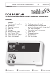
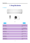
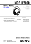
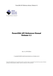
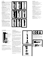
1. GENERAL
COMBINED PH ELECTRODES (NON-FLOW)
SC21(D)-AAP26
• pH, temperature range: 0 to 14 pH, 0 to 110 ºC.
• Maximum process pressure 500 kPa.
• Glass Resistance (25ºC): 250 to 400 MΩ.
• High quality Ag/AgCl reference system (pin)
which can stand high temperatures and temperature fluctuations.
• A large area PTFE junction to resist fouling to a
high degree.
• Chemical resistant, steam-sterillisable pH-glass.
SC21- AGP24 / ASP24
• pH, temperature range: 0 to 14 pH, 0 to 80 ºC.
• Maximum process pressure 500 kPa.
• G-Glass Resistance (25ºC): 50 to 100 MΩ.
• S-Glass Resistance (25ºC): 25 to 50 MΩ.
• Ag/AgCl wire reference system.
• pH bulb with cage protection (no breakage
when placed in a beaker).
• Less maintenance due to the gelled electrolyte
and porous PTFE.
• Thickened electrolyte (3.3M).
SC21(C)-AGP26
• pH, temperature range: 0 to 14 pH, -10 to 100 ºC.
• Maximum process pressure 500 kPa.
• Glass Resistance (25ºC): 120 to 200 MΩ.
• High quality Ag/AgCl reference system (pin)
which can stand high temperatures and
temperature fluctuations.
• Double junction (thickened saturated
KCl-solution). The built-in salt bridge prevents
poisoning of the reference system.
• Heavy duty glass membrane for prolonged
operation in corrosive, abrasive and fouling
environments (withstanding traces of HF).
• A large area PTFE junction to resist fouling.
SC21- ALP26
• pH, temperature range: 0 to 14 pH, 10 to 120 ºC.
• Maximum process pressure 500 kPa.
• Glass Resistance (25ºC): 600 to 900 MΩ.
• High quality Ag/AgCl reference system (pin)
which can stand high temperatures and
temperature fluctuations.
• Double junction (thickened saturated
KCl-solution). Built-in salt bridge prevents
poisoning of the reference system.
• Heavy duty glass membrane for prolonged
operation in corrosive, abrasive and fouling
environments (withstanding traces of HF).
• Large area PTFE junction to resist fouling.
• Chemical resistant, steam-sterillisable pH-glass.
23
Ø 17
SC21
Liquid outlet
2 = Non-flow
23 = Noryl housing and gelled
electrolyte
24 = Filled with gelled electrolyte
26 = Double junction filled with
gelled electrolyte
5= Flow
52 = Refillable at the top
55 = Heavy duty flow type
Diaphragm
C = Ceramic
P = PTFE (teflon)
Membrane
S = Low ohmic
G = Universal
L = high temperature
Reference system
A = Ag/AgCl (silver-silverchloride)
Connector type
= Yokogawa connector
D = Din connector
C = Compact connector
1.3. SPECIFICATIONS
The information about range, specifications, etc.
is clearly shown on the type plate attached to the
electrode cap.
The electrical resistance of the diaphragm is
<5kΩ at 25°C. Each temperature increase of
10°C halves the resistance of the membrane. The
resistance of the diaphragm depends on the type
of the electrode but must be max. 10 kΩ at 25°C
in all circumstances.
Wrench 17
26
Ø 17
23
PG13.5
Ø 12
120
120
120
Ø 12
SC21C-AGP64
• pH, temperature range: 0 to 14 pH, 0 to 80 ºC
• Maximum process pressure 500 kPa
• Glass Resistance (25ºC): 75 to 150 MΩ
• Ag/AgCl wire reference system
• Gelled electrolyte and porous PTFE.
• 3.3 molal KCl electrolyte
Ø 12
10
15
Fig. 1 SC21-AAP26
G 1/4"
Ø 15
Fig. 3 SC21-ASP23
Fig. 2 SC21D-AAP26
COMBINED PH ELECTRODES (FLOW)
18
G 1/4"
SC21C-AGC55
• Low ionic application. Positive flow of electrolyte provides the conductivity to measure pH
• Heavy duty pH sensitive glass.
• Flowing reference system for pollution resistance, and highly stable reference potential.
• PG13.5 standard DIN electrode connection.
• Use in combination with the presurisable
electrolyte reservoir to obtain a positive flow
towards the process (K1500YA)
23
Ø 17
91
PG13.5
DIN 40430
PG 13,5
DIN 40430
Ø 12
120
Ø 12
Ø 12
120
4
SC21-AGC11
• Refillable combined laboratory electrode.
• pH, temperature range: 0 to 14 pH, 0 to 80 ºC.
• Atmospheric pressure.
• Glass Resistance (25ºC): 50 to 100 MΩ.
• Ag/AgCl reference system.
4.5
Fig. 4 SC21-AGP24 / ASP24
Fig. 6 SC21C-AGC55
Fig. 5 SC21C-AGP64
G 1/4"
Ø 17
G 1/4"
23
Ø 17
G 1/4"
23
PG13.5
DIN 40430
Ø 17
23
Ø 12
120
Ø 12
120
120
Ø 12
10
10
Ø 11
Fig. 7 SC21-AGP26 / ALP26
1.2. TYPE NUMBER
The type number of a combined electrode is
arranged as follows:
SC21- ASP23
• Noryl Body (30% glass filled).
• Suitable for low temperatures.
• pH, temperature range: 0 to 10 pH, 0 to 80 ºC.
• Maximum process pressure 500 kPa.
• Glass Resistance (25ºC): 40 to 100 MΩ.
• Ag/AgCl wire reference system.
• Less maintenance by the combination of gelled
electrolyte and porous PTFE.
G 1/4"
G 1/4"
Fig. 8 SC21C-AGP26
Fig. 9 SC21-AGC11
2. INSTALLATION
Ø9
2.1. PREPARATION FOR USE
For accurate pH measurement a gel layer must
be formed on the membrane surface. For this
reason the pH sensitive part of the electrode
should be soaked for 24 hours before the
electrode is used.
Ø 15
Fig.12 YEF-connector
(set of 12 cable nuts).
When an electrode has been stored dry and you
need to use it immediately (there is no time for
soaking), you may do so, but as a result initial
regular calibration will be required until the gel
layer is formed.
2.2 MOUNTING
The combined electrodes must be connected
with a Coax cable type WU20(D)-PC.., marked
with a blue strip. In areas where electrical
interference is likely we recommend to use the
Triax electrode cable type WU20(D)-LT.. marked
with a blue strip. The cables meets the requirement of IP65 and can be used in temperatures
up to 70ºC (Triax) and 110ºC (Coax).
Fig. 13 D-connector
RESERVOIR FOR SC21C-AGC55
The reservoir, including connection kit and tubing,
can be ordered separately. The connection of the
tubing to the sensor is described in figure 14. At
the reservoir side Yokogawa provides a so called
swagelock connection.
The electrode when despatched by Yokogawa,
has a protective cover cap filled with water
around the membrane which ensures you can
use the electrode immediately. Flow electrodes
(types SC21C-AGC55) have a refill opening
which is sealed with a cap or stopper.
NOTE:
Before installation the above mentioned stopper
and protective covercap must be removed.
If required, the flow electrodes of the type
SC21C-AGC55 may be connected to a reservoir
of electrolyte solution. To maintain a correct flow,
in non-pressurised systems, the reservoir must
be placed so that the level of the electrolyte is
above the level of the measuring liquid. Only
under these circumstances will the correct
electrical contact between reference system and
measuring liquid be guaranteed.
16
Ø 17
NOTE: Avoid air bubbles in the tubing.
"O"-Ring
Ferrule
Lock-Ring
Nut
Tube
Fig.10 Standard mounting with mounting set
FP20-R12(M), FP20-S12(M)
5+3 mm
Fig. 14 Mounting the tube connection for the SC21C-AGC55
PG13.5
K1520JN
The cables above are fitted with the standard
Yokogawa nut (WU20-) or a DIN nut (WU20D-),
the dimensions of which are shown in figure 12.
The yokogawa nut can be ordered under part
number: K1500DW.
Fig.11 Mounting PG13,5 in Yokogawa fitting using the adapter
K1520JN (PVC-C) or K1500DV (PVDF)
3. USE AND MAINTENANCE
3.1. GENERAL
The isothermal point of intersection of the
electrode is at (pH 7 = 0 mV)
Regulary check there is sufficient electrolyte
solution in the electrode or in the reservoir.
The SC21C-AGC55 type sensor is filled with
a solution of 3.3 M KCI (i.e.246.9g KCI/1000 g
demi-water), which is available as spare part nr:
K1520VA.
The electrodes of the type SC21(D)-...2. are filled
with a gelled electrolyte solution and refilling is
not necessary. When there is insufficient electrolyte solution this type of electrode has probably
been used at at a temperature too high for this
electrode and therefore replacement by another
type of electrode is re-commended.
3.2 CALIBRATION AND BUFFERING
To calibrate a pH sensor, two buffer solutions with
known pH values are required. It is recommended
that one buffer solution has a value has near to
pH 7.00 (ITP). Depending on the process value to
be measured, the second buffer solution should
be either acidic (below 7.00) or alkaline (above
7.00). Normally, the IEC buffers (4.01, 6.87 and
9.18) are used. The following is a very general
2-point calibration procedure.
1.Clean the sensor (deposits may be removed
using a 5% (approximate) solution of HCL).
2.Rinse sensor thoroughly with clean
(demi) water.
3.Immerse the sensor in the first buffer
(6.87 pH is recommended).
4.Refer to appropriate Instrument Instruction
Manual for Calibration procedures
(Auto; Manual; Sample, etc.),
5.Rinse sensor thoroughly with clean
(demi) water.
6.Immerse the sensor in the second buffer
(4.01 or 9.18 recommended).
7.Repeat Step 4.
During calibration the temperature compensation
should be active. The instrument automatically
compensates for the sensitivity change of the
pH sensor at different temperatures. After the
calibration is complete replace or re-install the
sensor into the process.
NOTE: During buffering the liquid earth and the
temperature compensator must be connected.
The temperature of the buffer solution must be
within the limits of the technical specifications as
indicated on the type plate.
4. STORAGE
When an electrode is to remain unused for a long
period, it is necessary to fill the electrode completely with electrolyte solution, to close the refill
opening, and to fit the protective cover around
the membrane. This must be filled with water.
5. TROUBLE SHOOTING
Generally faults are caused by:
a. Sensitivity decrease of the membrane. When
this occurs the electrode must be cleaned with
a suitable detergent.
1. Depositions of hydroxydes lime, iron,
hydroxyde can be removed by immersing
the electrode in a diluted solution of hydrochloric acid and then rinsing with water.
2. Depositions of oil and fat can be removed
by means of hot water in conjunction with a
domestic washing solution. When the result
is unsatisfactory, a domestic abrasive may
be carefully used.
3. Albuminous depositions can be removed
by means of a solvent containing: 8,5 ml
concentrated hydrochloric acid, 10 g pepsin
and 1 liter demi-water.
NOTE: When polar solvents are used for special
cleaning purposes, it is necessary to
soak the electrode for some time after cleaning as the polar solvent influences the gel layer.
When an a-polar solvent is used (benzin, ether,
toluene) follow up treatment with a polar solvent
(methanol, aceton) is necessary.
b. Leakage to earth.
Fault indications can be expected when the
resistance between the reference system and
the screening falls below 107 Ω.
When a fault accurs, first check if the electrode
cable is in a good condition and check if the
connector contacts and the terminals in the
measuring instrument or connection box are
clean and dry.
c. Short circuit by break or leakage.
The pH meter reading remains approximately
pH 7 and is not dependant on the pH value of
the liquid being measured. If this occurs the
electrode should be replaced.
d. Diaphragm poisoning
Strongly poluted liquids can cause the diaphragm to foul very quickly, As a result, there
will be a transition resistance over the diaphragm. When this resistance exceeds 105Ω
instability of reading and incorrect
indication of the measured value will occur.
The above fault occurs frequently with flow
type electrodes when the flow of electrolyte
solution is insufficient e.g. with adverse
pressure variations due to the medium, pumps
or too low electrolyte level.
Fouled electrodes can be cleaned with hot
water in conjuntion with a domestic washing solution if necessary. When the fouling is
caused by fat or hydroxides (lime) cleaning
with a organic solvent or diluted acid respectively is recommended.
The ceramic diaphragm of electrode types
SC21(C)-AGC.. can be cleaned by lightly rubbing with fine emery paper. It may be necessary
with non-flow electrode types SC21(D)-...2. to
place the electrode for a period in an electrolyte
solution at 80°C and let them remain until the
solution has completely cooled.
e. Poisoning.
An electrode can be poisoned by the penetration of the process liquid or by diffusion of
components of the process medium through
the diaphragm. In addition, the inner liquid in
combination with dissolved particles from the
process medium may give deposits which
block the diaphragm (e.g. silver chloride +
sulfide -> deposits of silver sulfide).
When poisoning occurs replacement of the
electrode will normally be necessary. It is
recommended if poisoning of a non-flow
electrode occurs to use an alternative type of
electrode.
f. Poor conduction of the process liquid.
When the electrical conduction of process
liquid is very low, an unstability of reading will
occur. This problem may be cured either by
adding electrolyte solution to the process liquid
or, if this is not possible, by making the
reference input of the measuring instrument
high impedance.
YOKOGAWA ELECTRIC
CORPORATION
World Headquarters
9-32, Nakacho 2-chome, Musashino-shi
Tokyo 180-8750
Japan
www.yokogawa.com
YOKOGAWA
ELECTRIC ASIA Pte. LTD.
5 Bedok South Road
Singapore 469270
Singapore
www.yokogawa.com/sg
YOKOGAWA CORPORATION
OF AMERICA
2 Dart Road
Newnan GA 30265
USA
www.yokogawa.com/us
YOKOGAWA
CHINA CO. LTD.
3F Tower D
Cartelo Crocodile Building
No.568 West Tianshan Road
Changing District
Shanghai, China
www.yokogawa.com/cn
Euroweg 2
3825 HD Amersfoort
The Netherlands
www.yokogawa.com/eu
YOKOGAWA
MIDDLE EAST B.S.C.(c)
P.O. Box 10070, Manama
Building 577, Road 2516,
Busaiteen 225
Muharraq, Bahrain
www.yokogawa.com/bh
Yokogawa has an extensive sales
and distribution network.
Please refer to the European website
(www.yokogawa.com/eu) to contact
your nearest representative.
g. Degrading of the glass membrane.
Degrading has one or more of the following
effects:
– decrease of speed of response
– increase of the electrical resistance
– decrease of sensitivity
– zero point shift
The effect of aging of the electrodes makes
it necessary to carry out re-calibration of the
electrode system regularly. The frequency
depends on the required accuracy, the
composition of the sample to be measured
and the temperature.
e.g.:
If the life-time of an electrode is 100% at the
room temperature it will be 20% at 80°C and
only 5% at 120°C.
It is possible to re-activate an aged electrode
by immersing for 10 seconds in a P.V.C. beaker containing a solution of vinegar (1 mol) and
potassium fluoride (1 mol). Ratio 1:1. After this
the electrode must be cleaned carefully.
WARNING:
As a result of strong etching proporties of the
acid, the handling should be done carefully
and in consultation with a safety officer.
6. CHECK
A quick check for correct functioning of a
combined electrode can be made as follows.
First connect the reference lead of this electrode
to the reference input of a pH meter. A known
good reference electrode with the same reference system should be connected to the glass
electrode input of the meter. After immersing
both electrodes in a buffer solution the meter
reading should be stable and adjustable to
pH 7 (assymetry potential.)
If this is possible the reference part of the
electrode is functioning correctly.
A quick check of the correct functioning of
the pH part of the combined electrode can be
made by connecting the pH sensitive part to the
glass electrode input of a pH meter and a
known good reference electrode to the reference
lead of this meter. If the calibration procedure
described in 3.2 gives a correct adjustment the
pH sensitive part of the combined electrode is
functioning correctly.
User Manual
Directions
for use combined
pH Electrodes
IM 12B6J1-30E-E
09-1110 (A) I
Printed in The Netherlands,
Subject to change without notice
Copyright©