1
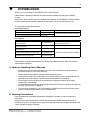
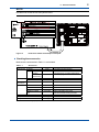
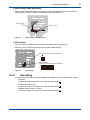
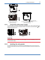
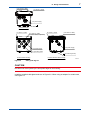
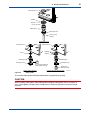
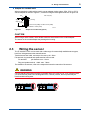
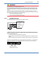
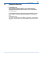
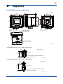
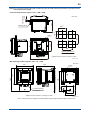
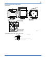
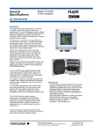
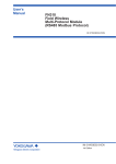
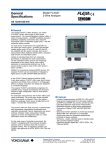
User’s Manual Model FLXA202 / FLXA21 2-Wire Analyzer Start-up Manual IM 12A01A02-12E This Start-up Manual explains mainly the installation and wiring of the FLXA202/FLXA21. For detailed information and other information, the User’s Manual of the FLXA202/FLXA21 should be referred to. IM 12A01A02-12E 8th Edition i uIntroduction Thank you for purchasing the FLXA202/FLXA21 2-Wire Analyzer. Please read the following respective documents before installing and using the FLXA202/ FLXA21. When the FLXA21 with the output of FOUNDATION Fieldbus or PROFIBUS PA Communication is used, please refer to the User’s Manual, IM 12A01A02-71E or IM 12A01A02-72E, too. The related documents are as follows. General Specifications Contents FLXA202 2-wire Analyzer FLXA21 2-wire Analyzer Document number GS 12A01A03-01EN GS 12A01A02-01E Note These are included In attached CD-ROM * the “E” or “EN” in the document number is the language code. User’s Manual Contents FLXA202/FLXA21 Start-up Manual FLXA202/FLXA21 Safety Precautions FLXA202/FLXA21 User’s Manual FLXA21 FOUNCATION Fieldbus Communication FLXA21 PROFIBUS PA Communication Document number IM 12A01A02-12E IM 12A01A02-20E Note This manual Attached to the product Attached to the product IM 12A01A02-01E IM 12A01A02-71E These are included In attached CD-ROM IM 12A01A02-72E * the “E” in the document number is the language code. Please read the General Specifications for Checking the model and suffix code. The General Specifications includes it. n Notes on Handling User’s Manuals • Please hand over the user’s manuals to your end users so that they can keep the user’s manuals on hand for convenient reference. • Please read the information thoroughly before using the product. • The purpose of these user’s manuals is not to warrant that the product is well suited to any particular purpose but rather to describe the functional details of the product. • No part of the user’s manuals may be transferred or reproduced without prior written consent from YOKOGAWA. • YOKOGAWA reserves the right to make improvements in the user’s manuals and product at any time, without notice or obligation. • If you have any questions, or you find mistakes or omissions in the user’s manuals, please contact our sales representative or your local distributor. n Drawing Conventions Some drawings may be partially emphasized, simplified, or omitted, for the convenience of description. Some screen images depicted in the user’s manual may have different display positions or character types (e.g., the upper / lower case). Also note that some of the images contained in this user’s manual are display examples. Media No. IM 12A01A02-12E 8th Edition : Oct. 2015 (YK) All Rights Reserved Copyright © 2010, Yokogawa Electric Corporation IM 12A01A02-12E 8th Edition : Oct. 01, 2015-00 ii n Authorised Representative in EEA The Authorised Representative for this product in EEA is Yokogawa Europe B.V. (Euroweg 2, 3825 HD Amersfoort, The Netherlands). IM 12A01A02-12E 8th Edition : Oct. 01, 2015-00 Toc-1 Model FLXA202 / FLXA21 2-Wire Analyzer Start-up Manual IM 12A01A02-12E 8th Edition CONTENTS uIntroduction.....................................................................................................i 1. Instrument Check..........................................................................................1 2. Wiring and Installation..................................................................................3 2.1 Installation site...................................................................................................... 3 2.2 Wiring the power supply...................................................................................... 3 2.2.1 Cables, terminals and glands for FOUNDATION Fieldbus or PROFIBUS PA.. 4 2.2.2Grounding.............................................................................................. 5 2.3 2.2.3 Connection of the power supply............................................................ 6 2.2.4 Installing the cable glands...................................................................... 6 Wiring the sensor.................................................................................................. 9 2.3.1 pH Measurement................................................................................. 10 2.3.2 ORP Measurement...............................................................................11 2.3.3 SC Measurement................................................................................. 12 2.3.4 ISC Measurement................................................................................ 13 2.3.5 DO Measurement................................................................................ 13 2.3.6 SENCOM pH/ORP Measurement....................................................... 14 2.3.7 Wiring of YOKOGAWA sensors........................................................... 15 2.3.8 Wiring of HAMILTON sensors.............................................................. 16 2.3.9 Wiring covers....................................................................................... 16 3.Operation..................................................................................................... 18 4. 3.1 Change language................................................................................................ 18 3.2 Quick setup.......................................................................................................... 18 3.3 Basic operation (when two sensors are connected)...................................... 19 Commissioning.......................................................................................... 20 5.Maintenance................................................................................................ 21 uAppendix..................................................................................................... 22 Revision Record........................................................................................................i IM 12A01A02-12E 8th Edition : Oct. 01, 2015-00 1. 1 <1. Instrument Check> Instrument Check Upon delivery, unpack the instrument carefully and inspect it to ensure that it was not damaged during shipment. If damage is found, retain the original packing materials (including the outer box) and then immediately notify the carrier and the relevant Yokogawa sales office. n Checking the model and suffix code lFLXA202 Make sure the model and suffix code on the nameplate affixed to the left side of the housing. NOTE Be sure to apply correct power to the unit , as detailed on the nameplate. -D-B-D-AB-P1-P1 -A-N-LA-N-N/U/H6 Figure 1.1 Inside of the FLXA202 and example of nameplate lFLXA21 Loosen four front panel screws of the FLXA21, open the panel to the left, and make sure the model and suffix code on the nameplate affixed to the back side of the front panel agrees with your order. CAUTION When you open the front panel, make sure the screws are completely out of the screw holes, and then open the front panel slowly in order not to damage the threaded parts on the housing. If the threaded parts are damaged and the screws cannot be tightened, the waterproof performance will deteriorate. IM 12A01A02-12E 8th Edition : Oct. 01, 2015-00 2 <1. Instrument Check> NOTE Be careful not to lose the four front panel screws. -D-P-S-AA-P1-NN-AN-L1N-NN /UM/SCT/H6 S1.01 J312FA012 Figure 1.2 2012.01 Inside of the FLXA21 and example of nameplate l Checking the accessories Make sure the accessories in Table 1.1 are included. Table 1.1 Accessories Product Name Cable glands FLXA202 FLXA21 Plastic housing Stainless steel housing pH analyzer Jumper Grommet set SENCOM Grommet pH analyzer Option Bracket Sun shade hood Tag plate Adapter for conduit work Instruction Manual (CD-ROM) Startup Manual Safety Precautions *: Quantity 3 sets 3 or 4 sets 3 sets Remark One rubber plug attachement. 4 sets when 2 sensors are used. One grommet for grounding attachement. One rubber plug attachement. 2 pcs/module 1 set/module 1 1 set 1 set 1 3 or 4 sets 1 copy 1 copy 1 copy Option code /UM*, /U, /PM Option code /H6, /H7, /H8 Option code /SCT Option code /CB4, /CD4, /CF4 4sets when Plastic housing are used. This manual The universal mounting kit (/UM) contains the brackets for both /U and /PM options. IM 12A01A02-12E 8th Edition : Oct. 01, 2015-00 2. 3 <2. Wiring and Installation> Wiring and Installation Open the front panel and remove the plastic wiring covers, and then install the cable glands (refer to the Appendix A1). The wiring covers will be re-installed after the wiring is completed. 2.1 Installation site The FLXA202/FLXA21 is weatherproof and can be installed both inside and outside. It should, however, be installed as close as possible to the sensor to avoid long cable runs between the instrument and sensor. When a pH sensor is used, the cable length including the sensor cable should not exceed 20 meters (65.6 feet); 60 meters (197 feet) when using BA10 extension box and WF10 cable. For a conductivity sensor the cable run should not exceed 60 meters (197 feet). For dissolved oxygen the sensor cable run should not exceed 30 meters (100 feet). For SENCOM pH/ORP the sensor cable run should not exceed 20 meters (65.6 feet). Select an installation site that meets the following conditions. • Mechanical vibrations and shocks are negligible • No relay switch and power switch are installed close to the converter • There is space for cable connection beneath the cable glands • Not exposed to direct sunlight or severe weather conditions • Maintenance is possible • No corrosive atmosphere • Ambient Operating Temperature: -20 to +55 °C • Humidity: 10 to 90% RH at 40 °C (Non-condensing) • Water Protection: IP66 (except Canada), NEMA 4X (except Canada), Type 3S/4X (Canada) If the instrument is installed outside and exposed to direct sunlight, a sun shade hood should be used. The FLXA202/FLXA21 can be mounted on a wall, pipe or panel when the mounting kit is ordered. For dimensional information please refer to the Appendix, Mounting methods. 2.2 Wiring the power supply FLXA202/FLXA21 is a 2-wire analyzer and can be powered by a DC power supply. • Output is FOUNDATION Filedbus and PROFIBUS PA option The Power Supply voltage is 9 to 32V DC. • Output is mA with HART The load resistance: impedance of electronic equipment: typically 250 Ohm Number of input modules: 1-sensor measurement or 2-sensor measurement. One (1) Sensor module (1 input): 16 to 40 V DC (for pH/ORP, SC and DO) 17 to 40 V DC (for ISC) 21 to 40 V DC (SENCOM pH/ORP) Two (2) Sensor modules (2 inputs): 22.8 to 40 V DC (for pH/ORP, SC and DO) IM 12A01A02-12E 8th Edition : Oct. 01, 2015-00 2-sensor measurement 1295 V - 11.5 R= 0.022 1000 600 Digital Communication Range (HART) 16 17 18 22.8 24.7 Figure 2.1Supply Voltage and Load Resistance for pH/ORP (analog sensor), SC and DO 2.2.1 R= 1000 V - 11.5 0.022 Except SENCOM 600 516 0 40 Voltage (V) 1295 Digital Communication Range (HART) 304 250 250 0 4 <2. Wiring and Installation> Load resistance (Ω) Load resistance (Ω) 22.86 24.7 17 18 18.2 21 Voltage (V) 40 Figure 2.2Supply Voltage and Load Resistance for ISC and pH/ORP SENCOM sensor Cables, terminals and glands for FOUNDATION Fieldbus or PROFIBUS PA Wire and install the system by referring to chapter 2 in the FLXA21 instruction manual (IM 12A01A02-01E). The FOUNDATION Fieldbus or PROFIBUS PA power supply is 9 to 32 V DC. The wiring is the same. However, for the FOUNDATION Fieldbus or PROFIBUS PA cables, see Table 2.1. Table 2.1 FOUNDATION Fieldbus or PROFIBUS PA Cables and transmissible Length Parameters Max DC Resistance, Ω/km Max Attenuation, dB/km Conditions per conductor 1.25 f, (39 kHz) Gauge — Max Length, meters — Type A 22 3.0 #18 AWG (0.82 mm2) 1,900 Type B 56 5.0 #22 AWG (0.32 mm2) 1,200 Type C 132 8.0 #26 AWG (0.13 mm2) 400 Type D 20 8.0 #16 AWG (1.25 mm2) 200 IM 12A01A02-12E 8th Edition : Oct. 01, 2015-00 Note: 1900 m is trunk + sum of Spurs (Max length type A cable) Yokogawa recommends the use of Type A. Usage of Type B and D is restricted. Yokogawa does not recommend the use of Type C. Table 2.2 Recommended length of Spur Cables Number of spur cables 15-16 13-14 1-12 Length of a non-intrinsically safe spur cable 60 m 90 m 120 m Note: • 1 device per spur. • Keep as short as possible (min 1 m) 5 <2. Wiring and Installation> l When using a SENCOM module When using a SENCOM module, you need to use the supplied cable clamp to fix the sensor cables in place. Attach the supplied cable clamp as shown in Figure 2.3. Sensor cable Cable cramp Figure 2.3 When using a SENCOM module l DIP switches Figure 2.4 shows the DIP switches for setting the address and write protection. Normally, you do not have the change them from the default settings. Write protection switch (Default: OFF) ON OFF Address switch (Default: Hardware address is disabled) ON OFF 7 6 5 4 3 2 1 0 Figure 2.4 2.2.2 DIP switches Grounding The way of connecting the grounding is different from Plastic housing, Stainless steel housing. • FLXA202 The ground cable is connected to the outer terminal marked • Plastic housing of FLXA21 The ground cable is connected to the inner terminal marked • Stainless steel housing of FLXA21 The ground cable is connected to the outer terminal marked IM 12A01A02-12E 8th Edition : Oct. 01, 2015-00 6 <2. Wiring and Installation> A: FLXA202 housing (External grounding) (Functional ground) B: FLXA21 Plastic housing (Internal grounding) 2.2.3 C: FLXA21 Stainless steel housing (External grounding) Connection of the power supply The power supply is connected to the terminals marked with + and – which corresponds with the polarity of the DC power supply. The shield of cable is connected to the terminal marked , then replace ground wiring cover. FLXA202 FLXA21 CAUTION The FLXA202/FLXA21 is used with a DC power supply. Do not use an alternating current or 100 volt mains power supply. 2.2.4 Installing the cable glands The supplied cable glands are for cables with an outside diameter of 6 to 12 mm (0.24 to 0.47 inches). Unused cable entry holes must be sealed with cable glands including the supplied close up plugs. IM 12A01A02-12E 8th Edition : Oct. 01, 2015-00 7 <2. Wiring and Installation> (For sensor 2 cable) For sensor 1 cable For power supply FLXA202 Housing For sensor 1 cable (For sensor 2 cable) (A hole is drilled, if specified.) For sensor 1 cable (For sensor 2 cable) For power supply For power supply For grounding cable (Functional ground) FLXA21 Plastic Housing Figure 2.5 FLXA21 Stainless Steel Housing F0202.ai Cable gland diagram CAUTION Be careful not to be injured by the sharp hole edges on the housing. Install the supplied cable gland as shown in Figure 2.6. When using an adapter for conduit work, see Figure 2.7. IM 12A01A02-12E 8th Edition : Oct. 01, 2015-00 8 <2. Wiring and Installation> Cable gland nut Gaskets Washer O-ring Gable gland Cable gland cap Close up plug (rubber) FLXA202 Housing Cable gland nut Cable gland nut Gaskets O-ring Washer Gable gland Gable gland Cable gland cap Sleeve (for grounding cable line of the plastic housing) FLXA21 Plastic Housing Figure 2.6 Cable gland cap Rubber plug (without wiring) FLXA21 Stainless Steel Housing F0203.ai Cable glands The unused cable glands should be sealed with the supplied close up plug. CAUTION When installing cable glands, hold cable glands and tighten cable gland nuts to a torque of 6 N•m. If cable glands, not gland nuts, are tightened, O-rings may be come out from the proper positions. IM 12A01A02-12E 8th Edition : Oct. 01, 2015-00 9 <2. Wiring and Installation> l Adapter for conduit work When protecting the cable with a conduit, use an adapter (option codes: /CB4, /CD4, or /CF4). Set the adapter as shown in figure 2.7, instead of using the cable gland as shown in figure 2.6. Unit: mm(inch) Nut Approx. 55(2.2") 49 (1.93") Adapter Figure2.7 Packing G1/2 screw (/CB4), 1/2 NPT screw (/CD4) M20x1.5 screw (/CF4) F0204.ai Adapter for conduit work (option) CAUTION When using a cable conduit, use a flexible conduit to avoid stress on the conduit adapter. The stress on the conduit adapter may damage the housing. 2.3 Wiring the sensor The FLXA202/FLXA21 can be used with a wide range of commercially available sensor types, both from Yokogawa and other manufacturers. Terminal screw size is M4, and torque of screw up is 1.2N•m Pin terminal, ring terminal and spade terminal can be used. Pin terminal: pin diameter: max. 1.9mm Ring and spade terminal: width: max. 7.8mm For details on the sensors, refer to the respective instruction manuals of the sensors. WARNING Confirm that all locking-tabs (including for BLANK slots) of FLXA21 are in “Lock” position before you close the front panel. If the locking-tabs are in “Unlock” position, the front panel may be interfered with locking-tabs. Unlock Lock IM 12A01A02-12E 8th Edition : Oct. 01, 2015-00 <2. Wiring and Installation> 10 WARNING Do not tighten up four front panel screws one by one. Each front panel screw should be tightened up in two times of screwing. And, firstly the screw at the upper left should be screwed a bit, the next is at the lower right, third is at the upper right, and fourth is at the lower left. The second round is the same sequence again to tighten up four screws. Do not use an electric screwdriver with high revolutions. If an electric screwdriver is used for these front panel screws, the revolutions of the electric screwdriver should be less than 400 rpm. Four screws should be tightened to the following torque; 0.8 to 0.9 N•m (for the plastic housing) 1.5 to 1.6 N•m (for the stainless steel housing) 2.3.1 pH Measurement Conventional pH sensors are connected to the module as follows: FLXA202/FLXA21 11 Temperature 12 Temperature 13 Reference 14 Solution ground 15 Glass (measure) 16 Shield 17 Shield TC REF Liquid PH Earth In addition to the wiring of the sensor, insure that a jumper for low-impedance sensor inputs is installed. The jumpers can be found on the plastic sensor module cover and can be stored in the lower level module wiring cover. • pH Glass Electrode is a high impedance sensor input • Standard reference electrodes and an ORP/REDOX electrode are low impedance sensor inputs • Special electrodes using 2 glass sensor (example: Pfaudler, SC24V) do not need jumpers. Terminals 15-16 are identified as input 1 (High Impedance) and terminals 13-17 are defined as input 2 (Low Impedance). For conventional pH sensors, the jumper is placed as illustrated: 11 12 14 18 13 17 19 15 16 PH Input 2 Input 1 Glass sensor on Input 1. Reference sensor on Input 2. IM 12A01A02-12E 8th Edition : Oct. 01, 2015-00 <2. Wiring and Installation> 2.3.2 11 ORP Measurement The ORP measurement uses the same sensor input module as the pH measurement. It is not uncommon to measure ORP as process variable and a pH Glass electrode as reference. This is the case with rH measurement and with pH compensated ORP measurement. Conventional ORP sensors are connected to the module as follows: FLXA202/FLXA21 11 Temperature 12 Temperature 13 Reference 14 Solution ground 15 Metal (measure) 16 Shield 17 Shield TC REF Liquid ORP Earth For conventional ORP sensors, the jumpers are placed as illustrated: 11 12 14 18 13 17 19 15 16 PH Input 2 Input 1 Metal sensor on Input 1. Normal reference on Input 2. pH Compensated ORP sensors are connected to the module as follows: FLXA202/FLXA21 11 Temperature 12 Temperature 13 Glass 14 Solution ground 15 Metal 16 Shield 17 Shield TC PH Liquid ORP Earth IM 12A01A02-12E 8th Edition : Oct. 01, 2015-00 <2. Wiring and Installation> 12 For pH Compensated ORP sensors, the jumper is placed as illustrated: 11 12 14 18 13 17 19 15 16 PH Input 2 Input 1 Metal sensor on Input 1. pH glass (as reference) on Input 2. NOTE The special grommet is intended to be used to seal the multiple cables from the Yokogawa flow fittings such as FF20. The designated cables are WU20 sensor cables, which are approximately 5 mm (0.2”) in diameter, and K1500FV liquid earth cables, which are approximately 2.5 mm (0.1”) in diameter. For sensor systems using a single cable, like the FU20/FU24 and the PR10, PD20, PF20 and PS20, the standard gland will accommodate the cable adequately. Single cables between approximately 6 mm and 12 mm (0.24” and 0.47”) can be sealed properly with these glands and the standard tule. Remove standard tule Sensor Grommet set Figure 2.8 2.3.3 Grommet set use SC Measurement Contacting Conductivity, SC, sensors are connected to the module as follows: FLXA202/FLXA21 11 + Temp 12 - 13 V14 i- 15 V+ 16 i+ IM 12A01A02-12E 8th Edition : Oct. 01, 2015-00 13 <2. Wiring and Installation> The above diagram shows wiring for 4-electrode conductivity sensors, such as SC42-SP34 large bore series. For 2-electrode conductivity sensors, such as SC42-SP36 small bore series, jumpers must be installed between terminals 13-14 and between terminals 15-16, as shown in the diagram below. FLXA202/FLXA21 11 + Temp 12 - 13 V14 i- 15 V+ 16 i+ 2.3.4 ISC Measurement ISC40 sensors are connected to the module as follows: FLXA202/FLXA21 11 + Temp 12 - 13 Receive coil 17 shield 14 Sensor shield (internal) 15 Drive coil 16 shield The sensors are supplied with integral cables and each individual wire is marked with the corresponding terminal numbers. 2.3.5 DO Measurement The input module for DO measurement is suitable for different types of DO sensors: i. Galvanic sensors like model DO30G ii. Polarographic sensors like HAMILTON’S Oxyferm and Oxygold The connection is as follows: IM 12A01A02-12E 8th Edition : Oct. 01, 2015-00 <2. Wiring and Installation> 14 FLXA202/FLXA21 11 TC + 12 TC 16 15 + anode galvanic 13 - cathode galvanic 18 + anode polarographic 14 shield 17 - cathode polarographic The DO30G sensor comes with integral cable and the wires are labeled with the corresponding terminal numbers. 2.3.6 SENCOM pH/ORP Measurement FU20F sensors are connected to the module as follows: Input M9 Connector Shield 82 4 Data+ 83 1 Data- 84 2 Supply Gnd 86 5 Supply 87 6 IM 12A01A02-12E 8th Edition : Oct. 01, 2015-00 15 <2. Wiring and Installation> 2.3.7 Wiring of YOKOGAWA sensors Sensor Measurement DO30G FU20 /PH20/FU24 FU20 /PH20/FU24 FU20 /PH20/FU24 FU20-VP /FU24-VP FU20-VP/ FU24-VP FU20-VP/ FU24-VP ISC40 PR20/PR10 DO pH, pH & ORP, rH ORP pH Comp. ORP pH, pH & ORP, rH ORP pH Comp. ORP ISC pH SC21 pH SC24V SC25V pH pH pH Comp. ORP SC29-PTG SC29-PTP ORP SC42 SC4A SM21/SR20 /SM60 SM29 /SR20 SC SC SX42 pH ORP SC 11 11 12 12 Board Terminals 13 14 15 13 14 15 16 16 17 11 12 13 16 17 11 12 13 14 11 12 15 14 E F B E F E 11 11 E E Yes Yes 13/14 Fixed Cable No Yes 13/14 Fixed Cable A Yes No B D Yes Yes 13/14 VP6-SC F A D No Yes 13/14 VP6-SC 12 12 13 13 Yes No Fixed Cable Fixed Cable No No WU20 Triax Yes No VP8-DC VP6-SC F F C B Red Blue 14 14 Liquid Earth H D Liquid Earth Liquid Earth 14 14 11 12 13 11 12 13 Green: Green: Yellow: Black Red Blue Red Yellow: Black Red Brown Brown Sensor Measurement FU20F pH, pH & ORP, rH Fixed Cable No D Yellow: Green 15 Remark Yes Blue 14 Input 2 Input 1 Jumper 18/13 19/15 16 15 15 16 16 Red (White) A A B Fixed Cable VP6-SC D Blue (White) Red (White) 15 15 Red: Red Red: Red 16 16 Red: Yellow: Blue Blue Red: Yellow: Blue Blue WU20 Triax Yes Yes WU20 Triax Yes No Yes Yes WU40 cable Fixed Cable WU20 Color Coded Coax WU20 Color Coded Coax 13/14 and 15/16 Red Board Terminals 82 83 84 86 87 82 83 84 86 87 IM 12A01A02-12E Sensor Wiring Remark WU11 Cable 8th Edition : Oct. 01, 2015-00 2.3.8 16 <2. Wiring and Installation> Wiring of HAMILTON sensors Sensor Measurement CHEMTRODE pH CHEMTRODEORP CHEMTRODEVP 11 12 13 Blue Red 17 18 (White) ORP pH CLARITRODE pH CLARITRODEVP pH CONDCUELL SC CONDCUELLVP SC EASYFERM pH E F E F B A Blue Red B A Blue Red pH E F B pH E F B MECOTRODE pH pH (White) Input 2 Input 1 Jumper Remark 18/13 19/15 WU20D Yes No 13/14 Cable Yes Yes 13/14 Yes No 13/14 VP6-SC Yes No 13/14 WU20D Cable Yes No White/ Blue Green Pink Brown Yellow Grey Black Grey Blue Yellow Black Grey Shield Shield EASYFERMVP INCHTRODE MECOTRODEVP OXYFERMVP/OXYGOLD Board Terminals 14 15 16 E F D Yes No A Yes No A Yes No Yes No Yes No Blue Red B A (White) (White) DO White Green Green/ Yellow Black OXYSENS DO Yellow Blue Black Clear Brown pHEASY pH POLILYTE pH POLILYTE-VP pH White Green Red POLILYTE PLUS-VP pH White Green Red E F B D A Blue Fixed Cable Hamilton VP Cable WU20D 13/14 Cable 13/14 13/14 (White) Black/ Clear Black/ Blue Clear Blue VP6-SC VP6-SC WU20D Cable VP8-DC Hamilton VP Cable Fixed Cable Red B Red VP6-SC Yes No Yes No Yes No Yes No WU20D Cable Hamilton VP Cable Hamilton VP Cable Color coding of Variopin cables PIN 2.3.9 A B C D E F Hamilton VP6-SC Black/ Clear Red Grey Blue White Green Hamilton VP8-DC Black/ Clear Black Shield Red/ Clear Red Shield White Green WU20-V-S VP6-SC Clear Brown Black Yellow Red Blue WU20-V-D VP8-DC Brown Core Brown Shield White Cored White Shield Red Blue G H Yellow Brown Yellow Wiring covers lFLXA202 NOTE Wiring covers are required intrinsic safety (Type is -C*). In the case of other types, the cover is not attached to the FLXA202. IM 12A01A02-12E 8th Edition : Oct. 01, 2015-00 17 <2. Wiring and Installation> When two sensor modules are used, the upper-level module is for input 1 and the lower-level module is for input 2. For ease of installation, first wire input 2 sensor on the lower-level module, and attach the wiring cover 1; then wire input 1 sensor on the upper-level module and replace the module wiring cover 2. The first module The second module Housing Wiring cover 2 (when using the second module) Wiring cover 1 lFLXA21 When two sensor modules are used, the upper-level module is for input 1 and the lower-level module is for input 2. For ease of installation, first wire input 2 sensor on the lower-level module (A), and attach the wiring cover; then wire input 1 sensor on the upper-level module (B) and replace the module wiring cover (C). (A) (B) (C) When all wiring is completed and all wiring covers have been installed, the front panel can be closed and the power can be switched on. IM 12A01A02-12E 8th Edition : Oct. 01, 2015-00 18 <3. Operation> 3.Operation When all wiring is completed, turn on the power to the instrument. Make sure that the LCD screen turns on, and then wait for the Quick Setup menu to be displayed. Follow the on-screen instructions for set-up and calibration. If the instrument is not configured correctly an error indicator may be displayed, or the measurement values displayed may be incorrect. Consult the User’s Manual supplied on CD with the analyzer, and check the initial settings and change them to suit your purpose. Basic operation of the software is similar the EXAxt 450 series. For more detailed information please refer to the User’s Manual of the FLXA202/FLXA21. 3.1 Change language The default language setting for the FLEXA is English. To select a different language other than English, follow the steps below. Quick setup Start quick setup? Yes No Change language Change language Chinese Czech English French German Italian Japanese Korean Polish Portuguese Portuguese Russian Russian Spanish Spanish 3.2 Warning The instrument will restart Are you sure? Yes Quick setup The Quick setup menu is used to program the basic items necessary to make the transmitter operational, such as the date/time and sensor settings. The detailed settings are described in the Commissioning in the User’s Manual (for example, chapter 4 for pH/ORP). Each time the FLXA202/FLXA21 is started up, this menu is displayed. If it is not necessary to change the setup, . When no operation is performed for you may bypass the Quick setup by selecting No or 10 minutes, the screen changes to the monitor display or the main display (or home display) automatically. IM 12A01A02-12E 8th Edition : Oct. 01, 2015-00 19 <3. Operation> MONITOR Display Quick setup 10.38 Start quick setup? Yes No Change language pH 3.3 Basic operation (when two sensors are connected) When 2 sensor modules are installed, the Home display shows both sensor information at one time, while the Main display will show the individual sensor information. If only one sensor is grayed out and disabled on the Main display. On the Home module is installed, the display, pressing the 1st sensor (top) information or the 2nd sensor (bottom) information causes the Main display of the selected sensor to appear. Home Display Tag:FLXA21–PH 25.0 °C 19 mV pH Tag:FLXA21–PH 24.9 °C 24 mV pH 4mA PH1 10.38 6.35 20mA Main Display Tag:FLXA21–PH 10.38 pH 25.0 °C 19 mV 4mA PH1 20mA IM 12A01A02-12E 8th Edition : Oct. 01, 2015-00 4. <4. Commissioning> 20 Commissioning NOTES for Quick Setup: a. pH measurement module Under “measurement “a selection is made for pH, ORP or pH&ORP. The selected measurement must be in accordance with the sensor wiring. When rH measurement is requested pH&ORP must be chosen on this level. The rH must then be selected in the commissioning menu. b. SC measurement module Under “measurement” a selection is made between Conductivity, Resistivity, Concentration or Concentration plus Conductivity. On this level only Conductivity or Resistivity can be selected. Settings for Concentration measurement must be done in the commissioning menu. c. DO measurement module Under “sensor type” a selection is made for Galvanic or Polarographic. The selected sensor type must be in accordance with the sensor wiring. Otherwise the analyzer or sensor can be damaged. IM 12A01A02-12E 8th Edition : Oct. 01, 2015-00 21 <5. Maintenance> 5.Maintenance n Periodic maintenance The FLXA202/FLXA21 requires very little periodic maintenance, except to make sure the front window is kept clean in order to permit a clear view of the display and allow proper operation of the touchscreen. If the window becomes soiled, clean it using a soft damp cloth or soft tissue. To deal with more stubborn stains, a neutral detergent may be used. When you must open the front cover and/or glands, make sure that the seals are clean and correctly fitted when the unit is re-assembled in order to maintain the housing’s weatherproof integrity against water and water vapor. The pH measurement uses high impedance sensors and may otherwise be prone to problems caused by exposure of the circuitry to condensation. CAUTION Never use harsh chemicals or solvents. In the event that the window does become heavily stained or scratched, refer to the parts list for replacement part numbers. IM 12A01A02-12E 8th Edition : Oct. 01, 2015-00 22 uAppendix nFLXA202 Dimensions and Mounting 80 137 165 40 Unit: mm 9 For sensor 1 cable For sensor 2 cable 80 165 146 4-M6 depth 7 For power supply 137 FB4_01.ai Conduit Adapter (Option code: /CB4, /CD4, /CF4) Unit: mm(inch) Nut Approx. 55(2.2") 49 (1.93") Adapter Packing G1/2 screw (/CB4), 1/2 NPT screw (/CD4) M20x1.5 screw (/CF4) F0204.ai Conduit Adapter (Option code: /CB5, /CD5, /CF5) Nut Approx. 64(2.52") Adapter Unit: mm(inch) Packing G1/2 screw (/CB5), 1/2 NPT screw (/CD5) M20x1.5 screw (/CF4) Conduit_Adapter_02.ai IM 12A01A02-12E 8th Edition : Oct. 01, 2015-00 23 (Note)The universal mounting kit (/UM) contains the pipe and wall mounting hardware (/U) and the panel mounting hardware (/PM). Panel mounting hardware (Option code: /PM, /UM) 121 Panel thickness 1 to 12 Unit: mm 2-M5 length 35 +1 100 195 4-M6 * +1 138 0 138 0 185 Spacing panel cutout *: Tighten the four screws to a torque of 2 N•m. 178 FB4-202_02.ai Wall mounting hardware (Option code: /U, /UM) 165 Unit: mm 168 4-M6 * 15 For wall mounting 3-ø10 holes 50 200 234.5 165 13 70 100 *: Tighten the four screws to a torque of 2 N•m. FB4-202_03.ai Note: The wall on which the analyzer is mounted should be strong enough to bear the weight of more than 8 kg. IM 12A01A02-12E 8th Edition : Oct. 01, 2015-00 24 Pipe mounting hardware (Option code: /U, /UM) Unit: mm 165 (209) 155 Pipe 50A (ø60.5) 50 200 184.5 4-M6 * M8 U-bolt Pipe mounting (Horizontal) Pipe mounting (Vertical) 100 *: Tighten the four screws to a torque of 2 N•m. FB4-202_04.ai Stainless steel hood (Option code: /H6, /H7, /H8) 220 Unit: mm 9 (50) 165 199 57 72 184 165 (70) (100) FB4-202_05.ai IM 12A01A02-12E 8th Edition : Oct. 01, 2015-00 25 nFLXA21 Dimensions and Mounting Plastic Housing 151 141 144 80 137 80 144 22.5 Unit: mm For sensor 1 cable 4-M6 depth 5 26.5 26.5 24.7 (For sensor 2 cable) For power supply 1 44.9 20.2 For grounding cable 137 FB4_01.ai Conduit Adapter (Option code: /CB4, /CD4, /CF4) Unit: mm(inch) Nut Approx. 55(2.2") 49 (1.93") Adapter Packing G1/2 screw (/CB4), 1/2 NPT screw (/CD4) M20x1.5 screw (/CF4) F0204.ai IM 12A01A02-12E 8th Edition : Oct. 01, 2015-00 26 (Note)The universal mounting kit (/UM) contains the pipe and wall mounting hardware (/U) and the panel mounting hardware (/PM). Panel mounting hardware (Option code: /PM, /UM) Panel thickness 1 to 12 Unit: mm 135 +1 138 0 +1 2-M5 length 35 138 0 100 195 4-M6 * 185 Spacing panel cutout *: Tighten the four screws to a torque of 2 N•m. 178 FB4_03.ai Wall mounting hardware (Option code: /U, /UM) Unit: mm 164 144 4-M6 * 50 For wall mounting 3-ø10 holes 15 200 224 144 13 70 100 *: Tighten the four screws to a torque of 2 N•m. FB4_02.ai Note: The wall on which the analyzer is mounted should be strong enough to bear the weight of more than 8 kg. Pipe mounting hardware (Option code: /U, /UM) Unit: mm (205) 151 Pipe 50A (ø60.5) 144 50 200 174 4-M6 * M8 U-bolt Pipe mounting (Horizontal) Pipe mounting (Vertical) *: Tighten the four screws to a torque of 2 N•m. 100 FB4_04.ai IM 12A01A02-12E 8th Edition : Oct. 01, 2015-00 27 Stainless steel hood (Option code: /H6, /H7, /H8) 184 144 9 Unit: mm (50) 199 144 57 72 220 (70) (100) FB4_05.ai Stainless Steel Housing 80 137 165 32.5 For sensor 1 cable (For sensor 2 cable) 80 165 Unit: mm 160 150 4-M6 depth 5 26.5 25.3 Plate (Only with coating) For power supply 44 22.2 137 FB4_06.ai Conduit Adapter (Option code: /CB4, /CD4, /CF4) Unit: mm(inch) Nut Approx. 55(2.2") 49 (1.93") Adapter Packing G1/2 screw (/CB4), 1/2 NPT screw (/CD4) M20x1.5 screw (/CF4) F0204.ai IM 12A01A02-12E 8th Edition : Oct. 01, 2015-00 28 (Note)The universal mounting kit (/UM) contains the pipe and wall mounting hardware (/U) and the panel mounting hardware (/PM). Panel mounting hardware (Option code: /PM, /UM) Panel thickness 1 to 12 Unit: mm +1 134 2-M5 length 35 138 0 +1 Plate (Only with coating) 138 0 100 195 4-M6 * 185 Spacing panel cutout *: Tighten the four screws to a torque of 2 N•m. 178 FB4_08.ai Wall mounting hardware (Option code: /U, /UM) 173 165 4-M6 * *: Tighten the four screws to a torque of 2 N•m. 15 For wall mounting 3-ø10 holes 50 200 234.5 165 13 Unit: mm 70 100 FB4_07.ai Note: The wall on which the analyzer is mounted should be strong enough to bear the weight of more than 8 kg. IM 12A01A02-12E 8th Edition : Oct. 01, 2015-00 29 Pipe mounting hardware (Option code: /U, /UM) Pipe 50A (ø60.5) (214) 165 Unit: mm 200 184.5 4-M6 * 50 160 Pipe mounting (Horizontal) Pipe mounting (Vertical) M8 U-bolt *: Tighten the four screws to a torque of 2 N•m. 100 FB4_09.ai Stainless steel hood (Option code: /H6, /H7, /H8) 220 Unit: mm 9 (50) 199 165 57 72 184 165 (70) (100) IM 12A01A02-12E FB4_10.ai 8th Edition : Oct. 01, 2015-00 i Revision Record Manual Title : Model FLXA202 / FLXA21 2-Wire Analyzer Start-up Manual Manual No. : IM 12A01A02-12E Oct. 2015/8th Edition Addition of FLXA202 Apr. 2015/7th Edition Change of “type of ground” of the stainless steel housing (pages 14 and 15) Note for wall mounting (pages 14 and 15) Oct. 2014/6th Edition Correction of discriptions and words Oct. 2013/5th Edition Addition of MONITOR display Correction of discriptions and words Sep. 2013/4rd Edition Pages are significantly reduced Feb. 2012/3rd Edition Addition of descriptions and drawings for intrinsically safe type Change of descriptions of messages on displays Change of figures of housing due to change of position of external grounding for stainless steel housing Change of figures of wiring covers Change of description of message language due to addition of message languages And, other corrections Aug. 2010/2nd Edition Followings are mainly revised; Addition of grounding terminal position on stainless housing with specific mountings Addition of plate position on stainless housing with specific coatings Addition of explanation of sleeve for grounding wire for plastic housing Correction of torques Addition of Note, Warning etc. Addition of detail descriptions for wire terminals Addition of drawings of housing with hood Addition of example displays for calculated data and redundant system Addition of explanation of passwords Correction of errors on the User setting tables May 2010/1st Edition Newly published IM 12A01A02-12E 8th Edition : Oct. 01, 2015-00