1
ÎÎ
GE Fanuc Automation
Programmable Control Products
CIMPLICITY 90-ADS
Alphanumeric Display System
Reference Manual
GFK-0641C
March 1994
GFL–002
Warnings, Cautions, and Notes
as Used in this Publication
Warning
Warning notices are used in this publication to emphasize that hazardous voltages,
currents, temperatures, or other conditions that could cause personal injury exist in this
equipment or may be associated with its use.
In situations where inattention could cause either personal injury or damage to
equipment, a Warning notice is used.
Caution
Caution notices are used where equipment might be damaged if care is not taken.
Note
Notes merely call attention to information that is especially significant to understanding
and operating the equipment.
This document is based on information available at the time of its publication. While
efforts have been made to be accurate, the information contained herein does not
purport to cover all details or variations in hardware or software, nor to provide for
every possible contingency in connection with installation, operation, or maintenance.
Features may be described herein which are not present in all hardware and software
systems. GE Fanuc Automation assumes no obligation of notice to holders of this
document with respect to changes subsequently made.
GE Fanuc Automation makes no representation or warranty, expressed, implied, or
statutory with respect to, and assumes no responsibility for the accuracy, completeness,
sufficiency, or usefulness of the information contained herein. No warranties of
merchantability or fitness for purpose shall apply.
The following are trademarks of GE Fanuc Automation North America, Inc.
Alarm Master
CIMPLICITY
CIMPLICITY 90–ADS
CIMPLICITY PowerTRAC
CIMSTAR
GEnet
Genius
Genius PowerTRAC
Helpmate
Logicmaster
Modelmaster
ProLoop
PROMACRO
Series One
Series Three
Series Five
Copyright 1991-1994 GE Fanuc Automation North America, Inc.
All Rights Reserved
Series Six
Series 90
VuMaster
Workmaster
Preface
Content of this Manual
This manual provides reference information for the CIMPLICITYr 90-ADS Alphanumeric
Display System that you will need to build a custom operator interface system for the Series
90-70 or Series 90-30 (Model 331 or Model 341) Programmable Logic Controller. The
CIMPLICITY 90-ADS software runs on the Alphanumeric Display Coprocessor (ADC)
module, and communicates over the Series 90-70 or Series 90-30 PLC’s backplane to monitor
and optionally modify data tables in the PLC.
Before using this reference manual to build an operator interface system you should read
GFK-0499, the CIMPLICITY 90-ADS User’s manual. That manual contains the information
you need on how to install the ADC module, select and setup the computer and terminal
you will be using, install the ADS software on your computer and download it to the ADC
module, view the demonstration systems, and walk through the development tutorial.
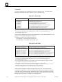
Revisions to This Manual
Appropriate changes have been made to this manual to reflect the features of Release 4.01 of
the CIMPLICITY 90-ADS Alphanumeric Display System. Additionally, corrections have been
made where necessary. Following is a list of the revisions to this manual as compared to the
previous version (GFK-0641).
GFK-0641
D
D
D
Page 1-3, added LUDCO.TBL to list of valid settings for terminal module.
D
D
D
D
D
D
D
D
D
Page 2-3, added note at bottom of page.
D
Chapter 9, added Section 7, ”Refresh System in RAM” and Section 8, ”Execute System in RAM”.
Page 1-4, added TTY.TBL to list of valid settings for printer module.
Page 2-2, changed README.251 to README.401 in second paragraph under ”Entering the
ADS Builder Program”.
Page 2-5, Revised column 4 of Table 2-1.
Page 2-6, changed README.251 to README.401 in fourth paragraph.
Page 3-3, added LUDCO... to list of terminals.
Page 3-29, added third sentence to CAUTION.
Page 6-7, added LUDCO after VT100 in column 1.
Page 6-10, changed content of items i - 5 in the list.
Page 6-11, added items 5 and 6 to list and added new paragraph after the list.
Page 9-1, added”Refresh System in RAM and Execute System in RAM” to first sentence in third
paragraph.
iii
Preface
D
Page 12-1, in item 1 of the list, deleted end of sentence beginning with ”as COM1...” and added
”appropriately”. Deleted item 2 from list.
D
Page 12-2, last paragraph, second sentence - changed ”your computer’s TERMF” to ”the target
terminal’s”. Added ”If your system...” to beginning of third sentence.
D
D
D
D
D
Added new Chapter 13, Options - PID.
D
D
D
D
D
Page 16-3, added NOTE after first paragraph. Deleted ”(see Appendix ...)” at end of item 3 in list.
Former Chapter 13 is now Chapter 14.
Former Chapter 14 is now Chapter 15.
Former Chapter 15 is now Chapter 16.
Page 16-1, added sentence beginning with ”Also, refer to ...” at end of paragraph under ”Overview
of the PID Module”.
Page 16-4, Added NOTE after first paragraph under ”Setup Screen”.
Page A-1, added LUDCO and TTY to ”ADS Menu Screen Items”.
Page A-2, added LUDCO to list of terminals under ”Modify System Parameters”.
Page A-9, changed several entries in column 4.
Content of this Manual
This manual contains the following information:
Chapter 1. ADS Main Menu describes the ADS menu screen which allows you to select
either the ADS Builder (create or modify a system) or the ADS Executor (execute an existing
system).
Chapter 2. Introduction to Using the ADS Builder provides a description of components
of an ADS system and how to begin using the system.
Chapters 3 through 10 describe the various submenus that you will use when creating an
Operator Interface System and guide you through the entries for each operation.
Chapter 3. Configuration Operations
Chapter 4. Screen Operations
Chapter 5. Report Operations
Chapter 6. Screen Painter and Report Painter
Chapter 7. Dynamic Objects
Chapter 8. Alarm Operations
Chapter 9. Load/Save Operations Using ADS Builder on ADC Module
Chapter 10. Print System Summary
Chapter 11. Exiting the ADS Builder describes how to exit the ADS Builder after building
or modifying a system.
Chapter 12. Terminal (ADS Offline PC-Based Builder Only)
Chapter 13. Options - PID describes how you can configure a PID module through the
Options PID menu without the need to use the PID option module’s built-in setup screen.
iv
CIMPLICITY90-ADS Alphanumeric Display System Reference Manual - March 1994
GFK-0641
Preface
Chapter 14. Running an ADS System: Starting the ADS Execution describes how a system
is executed, once it has been built with the ADS Builder, using the ADS Executor software. It
explains what you can expect when viewing data on the screen and how alarms are handled
during system execution.
Chapter 15. Fault Tables Module describes the optional PLC and I/O Fault Tables software
module which you can access from the ADS main menu.
Chapter 16. PID Templates Module describes the optional PID Templates software module
which you can access from the ADS main menu.
Appendix A. CIMPLICITY 90-ADS System Builder Guide provides a quick reference to
the ADS system setup parameters and parameter requirements for building an Operator
Interface System. A Key Functions pullout card provides a convenient listing of the
CIMPLICITY 90-ADS key functions.
Related Publications:
t
GFK-0499: CIMPLICITY 90-ADS Alphanumeric Display System User’s Manual. Explains how
to install the ADC module in a Series 90-30 or 90-70 PLC and download the ADS software
onto the module. Also included is information about the demonstration systems which let
you view the ADS system capabilities and a development tutorial which walks you through
development of an example operator interface system.
t
GFK-0255: Series 90 Programmable Coprocessor Module and Support Software User’s Manual.
Provides information required for configuration, programming and operation of the Series
90 Programmable Coprocessor Module (PCM).
t
GFK-0262: Series 90 -70 Programmable Controller Installation Manual. Provides the information
required for system planning and installation. Describes the hardware components of a
system and system configuration, and provides installation and field wiring information for
planning purposes and actual system installation.
GFK-0401: Workmasterr II PLC Programming Unit Guide to Operation. Describes installation
and operation of the Workmaster II computer, specifically when used as the programming
device for a Series 90 Programmable Logic Controller.
GFK-0263: Logicmastert 90 Programming Software User’s Manual. Explains how to use the
Logicmaster 90 software to configure the Series 90-70 Programmable Logic Controller and
create application programs.
GFK-0265: Series 90t-70 Programmable Controller Reference Manual. Describes the
programming instructions used to create application programs for the Series 90-70
Programmable Logic Controller. Provides fault explanations and corrections, and contains
CPU operation and performance data.
GFK-0466: Logicmastert 90-30 Programming Software User’s Manual. Explains how to use the
Logicmaster 90-30 software to configure the Series 90-30 Programmable Logic Controller and
create application programs.
GFK-0467: Series 90t-30/90-20 Programmable Controller Reference Manual. Describes the
programming instructions used to create application programs for the Series 90-30
Programmable Logic Controller.
GFK-0487: Series 90t Programmable Coprocessor Reference Manual. Describes how to use the
PCM programmer software (PCOP) and provides details for developing applications for the
PCM.
GFK-0641
Preface
v
Preface
GFK-0505: Operator Interface Terminal (OIT). Explains how to install, startup, and program the
OIT.
GFK-0361: Operator Interface Terminal, Mini OIT Supplement. Explains how to power up,
operate, and configure the Mini OIT.
We Welcome Your Comments and Suggestions
At GE Fanuc automation, we strive to produce quality technical documentation. After you
have used this manual, please take a few moments to complete and return the Reader’s
Comment Card located on the next page.
Henry A. Konat
Senior Technical Writer
vi
CIMPLICITY90-ADS Alphanumeric Display System Reference Manual - March 1994
GFK-0641
Contents
Chapter 1
Chapter 2
Chapter 3
ADS Main Menu . . . . . . . . . . . . . . . . . . . . . . . . . . . . . . . . . . . . . . . . . .
1-1
Filling-in the ADS Main Menu . . . . . . . . . . . . . . . . . . . . . . . . . . . . . . . . . . . . . .
Executor Debug Mode . . . . . . . . . . . . . . . . . . . . . . . . . . . . . . . . . . . . . . . . . . . . .
Exiting the ADS Main Menu . . . . . . . . . . . . . . . . . . . . . . . . . . . . . . . . . . . . . . . .
1-1
1-5
1-5
Introduction to Using the ADS Builder . . . . . . . . . . . . . . . . . . . . . . .
2-1
Components of an ADS System . . . . . . . . . . . . . . . . . . . . . . . . . . . . . . . . . . . . .
Entering the ADS Builder Program . . . . . . . . . . . . . . . . . . . . . . . . . . . . . . . . . .
Choosing Items From a Menu . . . . . . . . . . . . . . . . . . . . . . . . . . . . . . . . . . .
Managing the Builder’s Memory . . . . . . . . . . . . . . . . . . . . . . . . . . . . . . . . .
Errors Loading Screens and Reports . . . . . . . . . . . . . . . . . . . . . . . . . . . . . .
Object Lists . . . . . . . . . . . . . . . . . . . . . . . . . . . . . . . . . . . . . . . . . . . . . . . . . . .
2-1
2-2
2-4
2-6
2-6
2-7
ConfigurationOperations . . . . . . . . . . . . . . . . . . . . . . . . . . . . . . . . . . .
3-1
Section 1: Modify System Parameters . . . . . . . . . . . . . . . . . . . . . . . .
3-2
System Name . . . . . . . . . . . . . . . . . . . . . . . . . . . . . . . . . . . . . . . . . . . . . . . . .
Terminal . . . . . . . . . . . . . . . . . . . . . . . . . . . . . . . . . . . . . . . . . . . . . . . . . . . . . .
Terminal Device . . . . . . . . . . . . . . . . . . . . . . . . . . . . . . . . . . . . . . . . . . . . . . .
Printer Device . . . . . . . . . . . . . . . . . . . . . . . . . . . . . . . . . . . . . . . . . . . . . . . . .
Default Scan Rate . . . . . . . . . . . . . . . . . . . . . . . . . . . . . . . . . . . . . . . . . . . . . .
Default Alarm Scan Rate . . . . . . . . . . . . . . . . . . . . . . . . . . . . . . . . . . . . . . . .
Startup Screen . . . . . . . . . . . . . . . . . . . . . . . . . . . . . . . . . . . . . . . . . . . . . . . . .
Error Messages for Modify System Parameters . . . . . . . . . . . . . . . . . . . . .
Section 2: PLC Data Sources . . . . . . . . . . . . . . . . . . . . . . . . . . . . . . . .
New Data Source . . . . . . . . . . . . . . . . . . . . . . . . . . . . . . . . . . . . . . . . . . . . . .
Modify a Data Source . . . . . . . . . . . . . . . . . . . . . . . . . . . . . . . . . . . . . . . . . .
Delete a Data Source . . . . . . . . . . . . . . . . . . . . . . . . . . . . . . . . . . . . . . . . . . .
View Current Sources . . . . . . . . . . . . . . . . . . . . . . . . . . . . . . . . . . . . . . . . . .
List Sources . . . . . . . . . . . . . . . . . . . . . . . . . . . . . . . . . . . . . . . . . . . . . . . . . . .
Print Sources . . . . . . . . . . . . . . . . . . . . . . . . . . . . . . . . . . . . . . . . . . . . . . . . . .
Error Messages for PLC Data Sources . . . . . . . . . . . . . . . . . . . . . . . . . . . . .
Section 3: Display Formats . . . . . . . . . . . . . . . . . . . . . . . . . . . . . . . . .
New Display Format . . . . . . . . . . . . . . . . . . . . . . . . . . . . . . . . . . . . . . . . . . .
Name . . . . . . . . . . . . . . . . . . . . . . . . . . . . . . . . . . . . . . . . . . . . . . . . . . . . . . . .
Data Type . . . . . . . . . . . . . . . . . . . . . . . . . . . . . . . . . . . . . . . . . . . . . . . . . . . . .
Range . . . . . . . . . . . . . . . . . . . . . . . . . . . . . . . . . . . . . . . . . . . . . . . . . . . . . . . .
Actions Which Control the Appearance of an Object . . . . . . . . . . . . . . . .
Actions Which Cause an Event to Occur . . . . . . . . . . . . . . . . . . . . . . . . . . .
Modify a Display Format . . . . . . . . . . . . . . . . . . . . . . . . . . . . . . . . . . . . . . . .
Delete a Display Format . . . . . . . . . . . . . . . . . . . . . . . . . . . . . . . . . . . . . . . .
View Current Formats . . . . . . . . . . . . . . . . . . . . . . . . . . . . . . . . . . . . . . . . . .
List Formats . . . . . . . . . . . . . . . . . . . . . . . . . . . . . . . . . . . . . . . . . . . . . . . . . . .
Print Formats . . . . . . . . . . . . . . . . . . . . . . . . . . . . . . . . . . . . . . . . . . . . . . . . . .
Error Messages for Display Formats . . . . . . . . . . . . . . . . . . . . . . . . . . . . . .
GFK–0641C
CIMPLICITY 90-ADS Alphanumeric Display System Reference Manual –
March 1994
3-2
3-2
3-4
3-5
3-5
3-6
3-6
3-7
3-8
3-9
3-18
3-19
3-20
3-21
3-22
3-23
3-24
3-24
3-25
3-25
3-26
3-26
3-28
3-32
3-33
3-34
3-35
3-36
3-37
vii
Contents
Section 4: Translation Table . . . . . . . . . . . . . . . . . . . . . . . . . . . . . . . .
New Translation . . . . . . . . . . . . . . . . . . . . . . . . . . . . . . . . . . . . . . . . . . . . . . .
3-39
Modify a Translation . . . . . . . . . . . . . . . . . . . . . . . . . . . . . . . . . . . . . . . . . . .
3-43
Delete a Translation . . . . . . . . . . . . . . . . . . . . . . . . . . . . . . . . . . . . . . . . . . . .
3-44
View Current Entries . . . . . . . . . . . . . . . . . . . . . . . . . . . . . . . . . . . . . . . . . . .
3-45
List Translations . . . . . . . . . . . . . . . . . . . . . . . . . . . . . . . . . . . . . . . . . . . . . . .
3-46
Print Translations . . . . . . . . . . . . . . . . . . . . . . . . . . . . . . . . . . . . . . . . . . . . . .
3-47
Error Messages for Translation Tables . . . . . . . . . . . . . . . . . . . . . . . . . . . . .
3-48
Section 5: Engineering Units Conversion Table . . . . . . . . . . . . . . .
3-49
New Unit Conversion . . . . . . . . . . . . . . . . . . . . . . . . . . . . . . . . . . . . . . . . . .
3-50
Name . . . . . . . . . . . . . . . . . . . . . . . . . . . . . . . . . . . . . . . . . . . . . . . . . . . . . . . .
3-50
Engineering Units Conversion Equation . . . . . . . . . . . . . . . . . . . . . . . . . .
3-50
Specify Data Types . . . . . . . . . . . . . . . . . . . . . . . . . . . . . . . . . . . . . . . . . . . . .
3-51
Input Data Type . . . . . . . . . . . . . . . . . . . . . . . . . . . . . . . . . . . . . . . . . . . . . . .
3-52
Output Data Type . . . . . . . . . . . . . . . . . . . . . . . . . . . . . . . . . . . . . . . . . . . . . .
3-52
Modify a Unit Conversion . . . . . . . . . . . . . . . . . . . . . . . . . . . . . . . . . . . . . . .
3-53
Delete a Unit Conversion . . . . . . . . . . . . . . . . . . . . . . . . . . . . . . . . . . . . . . .
3-54
View Current Entries . . . . . . . . . . . . . . . . . . . . . . . . . . . . . . . . . . . . . . . . . . .
3-55
List Unit Conversion . . . . . . . . . . . . . . . . . . . . . . . . . . . . . . . . . . . . . . . . . . .
3-56
Print Unit Conversions . . . . . . . . . . . . . . . . . . . . . . . . . . . . . . . . . . . . . . . . .
3-57
Error Messages for Engineering Units Conversion Table . . . . . . . . . . . . .
3-58
Section 6: Lookup Table . . . . . . . . . . . . . . . . . . . . . . . . . . . . . . . . . . . .
3-59
New Lookup Table Entry . . . . . . . . . . . . . . . . . . . . . . . . . . . . . . . . . . . . . . .
3-60
Modify a Lookup Table Entry . . . . . . . . . . . . . . . . . . . . . . . . . . . . . . . . . . . .
3-65
Delete a Lookup Table Entry . . . . . . . . . . . . . . . . . . . . . . . . . . . . . . . . . . . . .
3-66
View Current Entries . . . . . . . . . . . . . . . . . . . . . . . . . . . . . . . . . . . . . . . . . . .
3-68
List Lookups . . . . . . . . . . . . . . . . . . . . . . . . . . . . . . . . . . . . . . . . . . . . . . . . . .
3-69
Print Lookups . . . . . . . . . . . . . . . . . . . . . . . . . . . . . . . . . . . . . . . . . . . . . . . . .
3-70
Error Messages for Lookup Table . . . . . . . . . . . . . . . . . . . . . . . . . . . . . . . . .
3-71
Section 7: Command Scripts . . . . . . . . . . . . . . . . . . . . . . . . . . . . . . . .
GFK–0641C
3-38
3-72
New Script . . . . . . . . . . . . . . . . . . . . . . . . . . . . . . . . . . . . . . . . . . . . . . . . . . . .
3-73
Modify a Script . . . . . . . . . . . . . . . . . . . . . . . . . . . . . . . . . . . . . . . . . . . . . . . .
3-82
Delete a Script . . . . . . . . . . . . . . . . . . . . . . . . . . . . . . . . . . . . . . . . . . . . . . . . .
3-83
View Current Scripts . . . . . . . . . . . . . . . . . . . . . . . . . . . . . . . . . . . . . . . . . . .
3-84
List Command Scripts . . . . . . . . . . . . . . . . . . . . . . . . . . . . . . . . . . . . . . . . . .
3-86
Print Command Scripts . . . . . . . . . . . . . . . . . . . . . . . . . . . . . . . . . . . . . . . . .
3-87
Error Messages for Command Scripts . . . . . . . . . . . . . . . . . . . . . . . . . . . . .
3-88
CIMPLICITY 90-ADS Alphanumeric Display System Reference Manual –
March 1994
viii
Contents
Chapter 4
Chapter 5
Chapter 6
Screen Operations . . . . . . . . . . . . . . . . . . . . . . . . . . . . . . . . . . . . . . . . .
4-1
New Screen . . . . . . . . . . . . . . . . . . . . . . . . . . . . . . . . . . . . . . . . . . . . . . . . . . . . . .
4-2
Modify Screen . . . . . . . . . . . . . . . . . . . . . . . . . . . . . . . . . . . . . . . . . . . . . . . . . . . .
4-7
Screen Paint . . . . . . . . . . . . . . . . . . . . . . . . . . . . . . . . . . . . . . . . . . . . . . . . . . . . .
4-7
Delete Screen . . . . . . . . . . . . . . . . . . . . . . . . . . . . . . . . . . . . . . . . . . . . . . . . . . . .
4-8
Copy Screen . . . . . . . . . . . . . . . . . . . . . . . . . . . . . . . . . . . . . . . . . . . . . . . . . . . . .
4-9
List Screens . . . . . . . . . . . . . . . . . . . . . . . . . . . . . . . . . . . . . . . . . . . . . . . . . . . . . .
Key Assignments . . . . . . . . . . . . . . . . . . . . . . . . . . . . . . . . . . . . . . . . . . . . . .
Touch Screen Assignments . . . . . . . . . . . . . . . . . . . . . . . . . . . . . . . . . . . . . .
4-10
4-11
4-13
Print Screen Details . . . . . . . . . . . . . . . . . . . . . . . . . . . . . . . . . . . . . . . . . . . . . . .
Error Messages for Screen Operations . . . . . . . . . . . . . . . . . . . . . . . . . . . .
4-14
4-17
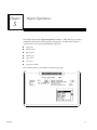
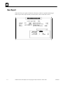
Report Operations . . . . . . . . . . . . . . . . . . . . . . . . . . . . . . . . . . . . . . . . .
5-1
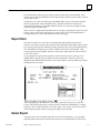
New Report . . . . . . . . . . . . . . . . . . . . . . . . . . . . . . . . . . . . . . . . . . . . . . . . . . . . .
5-2
Modify Report . . . . . . . . . . . . . . . . . . . . . . . . . . . . . . . . . . . . . . . . . . . . . . . . . . .
5-4
Report Paint . . . . . . . . . . . . . . . . . . . . . . . . . . . . . . . . . . . . . . . . . . . . . . . . . . . . .
5-5
Delete Report . . . . . . . . . . . . . . . . . . . . . . . . . . . . . . . . . . . . . . . . . . . . . . . . . . . .
5-5
Copy Report . . . . . . . . . . . . . . . . . . . . . . . . . . . . . . . . . . . . . . . . . . . . . . . . . . . . .
5-6
List Report . . . . . . . . . . . . . . . . . . . . . . . . . . . . . . . . . . . . . . . . . . . . . . . . . . . . . . .
5-6
Print Report Details . . . . . . . . . . . . . . . . . . . . . . . . . . . . . . . . . . . . . . . . . . . . . . .
Error Messages for Report Operations . . . . . . . . . . . . . . . . . . . . . . . . . . . .
5-7
5-8
Screen Painter and Report Painter . . . . . . . . . . . . . . . . . . . . . . . . . . . .
6-1
Section 1: ADS Screen Painter Keyboard . . . . . . . . . . . . . . . . . . . . .
6-2
Section 2: Moving the Cursor . . . . . . . . . . . . . . . . . . . . . . . . . . . . . . .
6-3
Section 3: Controlling the Screen Attributes . . . . . . . . . . . . . . . . . .
6-4
Section 4: Selecting Foreground Colors While Editing . . . . . . . . .
6-5
Section 5: Selecting the Character Set . . . . . . . . . . . . . . . . . . . . . . . .
6-7
Selecting Double Wide and Double High/Wide Characters . . . . . . . . . . .
Simulating Quad Size Characters . . . . . . . . . . . . . . . . . . . . . . . . . . . . . . . .
Section 6: Entering Static Text . . . . . . . . . . . . . . . . . . . . . . . . . . . . . .
6-11
Section 7: Deleting and Undeleting Lines . . . . . . . . . . . . . . . . . . . .
6-12
Section 8: Selecting a Region . . . . . . . . . . . . . . . . . . . . . . . . . . . . . . .
6-14
Section 9: Drawing Horizontal and Vertical Lines . . . . . . . . . . . . .
6-19
Section 10: Cut and Paste . . . . . . . . . . . . . . . . . . . . . . . . . . . . . . . . . . .
6-22
Cutting a Region . . . . . . . . . . . . . . . . . . . . . . . . . . . . . . . . . . . . . . . . . . . . . . .
Pasting a Region . . . . . . . . . . . . . . . . . . . . . . . . . . . . . . . . . . . . . . . . . . . . . . .
GFK–0641C
6-9
6-10
CIMPLICITY 90-ADS Alphanumeric Display System Reference Manual –
March 1994
6-22
6-23
ix
Contents
Section 11: Touch Points . . . . . . . . . . . . . . . . . . . . . . . . . . . . . . . . . . .
Chapter 7
Chapter 8
Accessing the Screen/Report Editor Help Screen . . . . . . . . . . . . . . . . . . . .
6-26
Exiting the Screen/Report Editor . . . . . . . . . . . . . . . . . . . . . . . . . . . . . . . . .
6-26
Miscellaneous Hints . . . . . . . . . . . . . . . . . . . . . . . . . . . . . . . . . . . . . . . . . . . .
6-27
Error Messages for Screen Painter and Report Painter . . . . . . . . . . . . . . .
6-28
Dynamic Objects . . . . . . . . . . . . . . . . . . . . . . . . . . . . . . . . . . . . . . . . . .
7-1
Creating a Dynamic Object . . . . . . . . . . . . . . . . . . . . . . . . . . . . . . . . . . . . . .
7-1
Available for Edit . . . . . . . . . . . . . . . . . . . . . . . . . . . . . . . . . . . . . . . . . . . . . .
7-9
Modifying a Dynamic Object . . . . . . . . . . . . . . . . . . . . . . . . . . . . . . . . . . . .
7-10
Deleting a Dynamic Object . . . . . . . . . . . . . . . . . . . . . . . . . . . . . . . . . . . . . .
7-11
Copying and Pasting a Dynamic Object . . . . . . . . . . . . . . . . . . . . . . . . . . .
7-13
Creating a Predefined Dynamic Object . . . . . . . . . . . . . . . . . . . . . . . . . . .
7-15
Error Messages for Dynamic Objects . . . . . . . . . . . . . . . . . . . . . . . . . . . . .
7-17
Alarm Operations . . . . . . . . . . . . . . . . . . . . . . . . . . . . . . . . . . . . . . . . . .
8-1
Section 1: Introduction to Using Alarms . . . . . . . . . . . . . . . . . . . . .
8-1
Section 2: New Alarm Page . . . . . . . . . . . . . . . . . . . . . . . . . . . . . . . . .
8-3
Modify an Alarm Page . . . . . . . . . . . . . . . . . . . . . . . . . . . . . . . . . . . . . . . . . .
8-8
Delete an Alarm Page . . . . . . . . . . . . . . . . . . . . . . . . . . . . . . . . . . . . . . . . . .
8-9
View Alarm Pages . . . . . . . . . . . . . . . . . . . . . . . . . . . . . . . . . . . . . . . . . . . . .
8-10
List Pages . . . . . . . . . . . . . . . . . . . . . . . . . . . . . . . . . . . . . . . . . . . . . . . . . . . . .
8-11
Print Page Details . . . . . . . . . . . . . . . . . . . . . . . . . . . . . . . . . . . . . . . . . . . . . .
8-12
Error Messages for Alarm Pages . . . . . . . . . . . . . . . . . . . . . . . . . . . . . . . . . .
8-13
Alarm Sources . . . . . . . . . . . . . . . . . . . . . . . . . . . . . . . . . . . . . . . . . . . . . . . . .
8-14
Section 3: New Alarm Source . . . . . . . . . . . . . . . . . . . . . . . . . . . . . . .
GFK–0641C
6-24
8-15
Modify an Alarm Source . . . . . . . . . . . . . . . . . . . . . . . . . . . . . . . . . . . . . . . .
8-34
Delete an Alarm Source . . . . . . . . . . . . . . . . . . . . . . . . . . . . . . . . . . . . . . . . .
8-35
Copy an Alarm Source . . . . . . . . . . . . . . . . . . . . . . . . . . . . . . . . . . . . . . . . . .
8-36
View Current Sources . . . . . . . . . . . . . . . . . . . . . . . . . . . . . . . . . . . . . . . . . .
8-37
List Sources . . . . . . . . . . . . . . . . . . . . . . . . . . . . . . . . . . . . . . . . . . . . . . . . . . .
8-39
Print Sources . . . . . . . . . . . . . . . . . . . . . . . . . . . . . . . . . . . . . . . . . . . . . . . . . .
8-40
Error Messages for Alarm Sources . . . . . . . . . . . . . . . . . . . . . . . . . . . . . . . .
8-42
CIMPLICITY 90-ADS Alphanumeric Display System Reference Manual –
March 1994
x
Contents
Chapter 9
Load/Save Operations . . . . . . . . . . . . . . . . . . . . . . . . . . . . . . . . . . . . . .
9-1
Section 1: Load System . . . . . . . . . . . . . . . . . . . . . . . . . . . . . . . . . . . .
9-3
Section 2: Save System to RAM:/Disk . . . . . . . . . . . . . . . . . . . . . . .
9-6
Section 3: Archive System to PC: . . . . . . . . . . . . . . . . . . . . . . . . . . .
9-9
Section 4: Clear System . . . . . . . . . . . . . . . . . . . . . . . . . . . . . . . . . . .
9-10
Section 5: Modify Current Directory . . . . . . . . . . . . . . . . . . . . . . . .
9-12
Section 6: Print Destination . . . . . . . . . . . . . . . . . . . . . . . . . . . . . . . .
9-13
Print Destination for ADS Builder on ADC Module . . . . . . . . . . . . . . . . .
Print Destination for PC-Based Builder . . . . . . . . . . . . . . . . . . . . . . . . . . . .
9-13
9-13
Section 7: Refresh System in RAM . . . . . . . . . . . . . . . . . . . . . . . . . .
9-14
Section 8: Execute System in RAM . . . . . . . . . . . . . . . . . . . . . . . . . .
9-16
Error Messages for Load/Save Operations . . . . . . . . . . . . . . . . . . . . . . . . .
9-17
Chapter 10
Print System Summary . . . . . . . . . . . . . . . . . . . . . . . . . . . . . . . . . . . . .
10-1
Chapter 11
Exiting the ADS Builder . . . . . . . . . . . . . . . . . . . . . . . . . . . . . . . . . . . .
11-1
Chapter 12
Terminal (ADS Off-line, PC-Based Builder Only) . . . . . . . . . . . . . .
12-1
Chapter 13
Options PID . . . . . . . . . . . . . . . . . . . . . . . . . . . . . . . . . . . . . . . . . . . . . . .
13-1
Create Loop . . . . . . . . . . . . . . . . . . . . . . . . . . . . . . . . . . . . . . . . . . . . . . . . . . .
Modify Loop . . . . . . . . . . . . . . . . . . . . . . . . . . . . . . . . . . . . . . . . . . . . . . . . . .
Delete Loop . . . . . . . . . . . . . . . . . . . . . . . . . . . . . . . . . . . . . . . . . . . . . . . . . . .
Load File . . . . . . . . . . . . . . . . . . . . . . . . . . . . . . . . . . . . . . . . . . . . . . . . . . . . .
Save File . . . . . . . . . . . . . . . . . . . . . . . . . . . . . . . . . . . . . . . . . . . . . . . . . . . . . .
Exit Options PID Screen . . . . . . . . . . . . . . . . . . . . . . . . . . . . . . . . . . . . . . . .
13-2
13-3
13-3
13-4
13-5
13-7
Running an ADS System:
Starting the ADS Execution . . . . . . . . . . . . . . . . . . . . . . . . . . . . . .
14-1
Section 1: Initial Startup . . . . . . . . . . . . . . . . . . . . . . . . . . . . . . . . . . .
14-2
Section 2: Viewing Data on a Screen . . . . . . . . . . . . . . . . . . . . . . . .
14-2
Section 3: Operator Prompts and Messages . . . . . . . . . . . . . . . . . .
14-3
Section 4: Alarm Handling During System Execution . . . . . . . . .
14-3
Chapter 14
Alarms Not Associated with Alarm Pages . . . . . . . . . . . . . . . . . . . . . . . . .
Alarms Associated with Alarm Pages . . . . . . . . . . . . . . . . . . . . . . . . . . . . .
GFK–0641C
CIMPLICITY 90-ADS Alphanumeric Display System Reference Manual –
March 1994
14-3
14-3
xi
Contents
Section 5: Printing Data to a Printer . . . . . . . . . . . . . . . . . . . . . . . . .
14-9
Section 6: Exit Executor . . . . . . . . . . . . . . . . . . . . . . . . . . . . . . . . . . . .
14-9
Error Messages for Running an ADS System: Starting the ADS Execution . . . . . .
14-10
Chapter 15
Chapter 16
GFK–0641C
Fault Tables Module . . . . . . . . . . . . . . . . . . . . . . . . . . . . . . . . . . . . . . . .
15-1
Overview of the Fault Tables Module . . . . . . . . . . . . . . . . . . . . . . . . . . . . .
15-1
Running the Fault Tables Module in Stand Alone Mode . . . . . . . . . . . . .
15-1
Accessing the Fault Module From an ADS System . . . . . . . . . . . . . . . . . .
15-1
Using the Fault Tables Module . . . . . . . . . . . . . . . . . . . . . . . . . . . . . . . . . . .
15-2
PID Templates Module . . . . . . . . . . . . . . . . . . . . . . . . . . . . . . . . . . . . .
16-1
Overview of the PID Module . . . . . . . . . . . . . . . . . . . . . . . . . . . . . . . . . . . . . . .
16-1
Running the PID Module in Stand Alone Mode . . . . . . . . . . . . . . . . . . . .
16-1
Accessing the PID Module From an ADS System . . . . . . . . . . . . . . . . . . .
16-2
General Operation of the PID Module . . . . . . . . . . . . . . . . . . . . . . . . . . . .
16-2
PID Startup File . . . . . . . . . . . . . . . . . . . . . . . . . . . . . . . . . . . . . . . . . . . . . . .
16-3
PID Module Screens . . . . . . . . . . . . . . . . . . . . . . . . . . . . . . . . . . . . . . . . . . . .
16-4
Setup Screen . . . . . . . . . . . . . . . . . . . . . . . . . . . . . . . . . . . . . . . . . . . . . . . . . .
16-4
Loop Configuration Screen . . . . . . . . . . . . . . . . . . . . . . . . . . . . . . . . . . . . . .
16-10
Loop Monitoring Screen . . . . . . . . . . . . . . . . . . . . . . . . . . . . . . . . . . . . . . . .
16-14
Loop Tuning Screen . . . . . . . . . . . . . . . . . . . . . . . . . . . . . . . . . . . . . . . . . . . .
16-18
CIMPLICITY 90-ADS Alphanumeric Display System Reference Manual –
March 1994
xii
Contents
Appendix A
GFK–0641C
CIMPLICITY 90-ADS
Display System Builder Guide . . . . . . . . . . . . . . . . . . . . . . . . . . .
A-1
ADS Menu Screen Items . . . . . . . . . . . . . . . . . . . . . . . . . . . . . . . . . . . . . . . . . . .
A-1
Configuration Operations . . . . . . . . . . . . . . . . . . . . . . . . . . . . . . . . . . . . . . . . . .
A-2
Modify System Parameters . . . . . . . . . . . . . . . . . . . . . . . . . . . . . . . . . . . . . .
A-2
PLC Data Source . . . . . . . . . . . . . . . . . . . . . . . . . . . . . . . . . . . . . . . . . . . . . . .
A-2
Display Formats . . . . . . . . . . . . . . . . . . . . . . . . . . . . . . . . . . . . . . . . . . . . . . .
A-3
Translation Table . . . . . . . . . . . . . . . . . . . . . . . . . . . . . . . . . . . . . . . . . . . . . . .
A-4
Lookup Table . . . . . . . . . . . . . . . . . . . . . . . . . . . . . . . . . . . . . . . . . . . . . . . . . .
A-4
Engineering Units Conversion Table . . . . . . . . . . . . . . . . . . . . . . . . . . . . . .
A-5
Command Scripts . . . . . . . . . . . . . . . . . . . . . . . . . . . . . . . . . . . . . . . . . . . . . .
A-5
Screen Operations . . . . . . . . . . . . . . . . . . . . . . . . . . . . . . . . . . . . . . . . . . . . . . . .
A-6
New/ModifyScreen . . . . . . . . . . . . . . . . . . . . . . . . . . . . . . . . . . . . . . . . . . . .
A-6
Key Assignments . . . . . . . . . . . . . . . . . . . . . . . . . . . . . . . . . . . . . . . . . . . . . .
A-7
Report Operations . . . . . . . . . . . . . . . . . . . . . . . . . . . . . . . . . . . . . . . . . . . . . . . .
A-8
New/ModifyReport . . . . . . . . . . . . . . . . . . . . . . . . . . . . . . . . . . . . . . . . . . . .
A-8
Screen/ReportEditing . . . . . . . . . . . . . . . . . . . . . . . . . . . . . . . . . . . . . . . . . . . . .
A-8
Screen Attributes . . . . . . . . . . . . . . . . . . . . . . . . . . . . . . . . . . . . . . . . . . . . . .
A-9
Create Dynamic Object . . . . . . . . . . . . . . . . . . . . . . . . . . . . . . . . . . . . . . . . .
A-10
Alarm Operations . . . . . . . . . . . . . . . . . . . . . . . . . . . . . . . . . . . . . . . . . . . . . . . .
A-10
New/ModifyAlarm Page . . . . . . . . . . . . . . . . . . . . . . . . . . . . . . . . . . . . . . .
A-10
Alarm Sources . . . . . . . . . . . . . . . . . . . . . . . . . . . . . . . . . . . . . . . . . . . . . . . . .
A-11
New/ModifyAlarm Sources . . . . . . . . . . . . . . . . . . . . . . . . . . . . . . . . . . . . .
A-11
CIMPLICITY 90-ADS Alphanumeric Display System Reference Manual –
March 1994
xiii
Contents
Figure 2-1. ADS System - Major Components and Interconnections . . . . . . . . . . . . . . . . . . . . . . . . . . .
GFK–0641C
CIMPLICITY 90-ADS Alphanumeric Display System Reference Manual –
March 1994
2-1
xiv
Contents
Table 2-1. Key Functions for System Building . . . . . . . . . . . . . . . . . . . . . . . . . . . . . . . . . . . . . . . . . . . . . . .
Table 3-1. Source Data Type Supported for Data Sources . . . . . . . . . . . . . . . . . . . . . . . . . . . . . . . . . . . . .
Table 3-2. Series 90 PLC References Supported by ADS System . . . . . . . . . . . . . . . . . . . . . . . . . . . . . . .
Table 3-3. Data Range for a Custom Translation . . . . . . . . . . . . . . . . . . . . . . . . . . . . . . . . . . . . . . . . . . . . .
Table 3-4. Source Data Types for Display Formats . . . . . . . . . . . . . . . . . . . . . . . . . . . . . . . . . . . . . . . . . . .
Table 3-5. Actions Which Control Appearance of an Object . . . . . . . . . . . . . . . . . . . . . . . . . . . . . . . . . . .
Table 3-6. Get PLC Data . . . . . . . . . . . . . . . . . . . . . . . . . . . . . . . . . . . . . . . . . . . . . . . . . . . . . . . . . . . . . . . . .
Table 3-7. Set PLC Data . . . . . . . . . . . . . . . . . . . . . . . . . . . . . . . . . . . . . . . . . . . . . . . . . . . . . . . . . . . . . . . . .
Table 3-8. Screen Commands . . . . . . . . . . . . . . . . . . . . . . . . . . . . . . . . . . . . . . . . . . . . . . . . . . . . . . . . . . . .
Table 3-9. Alarm Page Commands . . . . . . . . . . . . . . . . . . . . . . . . . . . . . . . . . . . . . . . . . . . . . . . . . . . . . . . .
Table 3-10. Alarm Source Related Commands . . . . . . . . . . . . . . . . . . . . . . . . . . . . . . . . . . . . . . . . . . . . . .
Table 3-11. Option Module Access Commands . . . . . . . . . . . . . . . . . . . . . . . . . . . . . . . . . . . . . . . . . . . . .
Table 3-12. Dynamic Object Related Commands . . . . . . . . . . . . . . . . . . . . . . . . . . . . . . . . . . . . . . . . . . . .
Table 3-13. Miscellaneous Commands . . . . . . . . . . . . . . . . . . . . . . . . . . . . . . . . . . . . . . . . . . . . . . . . . . . . .
Table 3-14. Data Range for a Translation Equation . . . . . . . . . . . . . . . . . . . . . . . . . . . . . . . . . . . . . . . . . . .
Table 3-15. Input Data Types Supported for Translation Tables . . . . . . . . . . . . . . . . . . . . . . . . . . . . . . . .
Table 3-16. Output Data Types Supported for Translation Tables . . . . . . . . . . . . . . . . . . . . . . . . . . . . . .
Table 3-17. Input Data Types Supported for EUC Tables . . . . . . . . . . . . . . . . . . . . . . . . . . . . . . . . . . . . . .
Table 3-18. Output Data Types Supported for EUC Tables . . . . . . . . . . . . . . . . . . . . . . . . . . . . . . . . . . . .
Table 3-19. Input Data Types Supported for Lookup Tables . . . . . . . . . . . . . . . . . . . . . . . . . . . . . . . . . . .
Table 3-20. Output Data Types Supported for Lookup Tables . . . . . . . . . . . . . . . . . . . . . . . . . . . . . . . . .
Table 3-21. Get PLC Data . . . . . . . . . . . . . . . . . . . . . . . . . . . . . . . . . . . . . . . . . . . . . . . . . . . . . . . . . . . . . . . .
Table 3-22. Set PLC Data . . . . . . . . . . . . . . . . . . . . . . . . . . . . . . . . . . . . . . . . . . . . . . . . . . . . . . . . . . . . . . . .
Table 3-23. Screen Commands . . . . . . . . . . . . . . . . . . . . . . . . . . . . . . . . . . . . . . . . . . . . . . . . . . . . . . . . . . .
Table 3-24. Alarm Page Commands . . . . . . . . . . . . . . . . . . . . . . . . . . . . . . . . . . . . . . . . . . . . . . . . . . . . . . .
Table 3-25. Alarm Source Related Commands . . . . . . . . . . . . . . . . . . . . . . . . . . . . . . . . . . . . . . . . . . . . . .
Table 3-26. Option Module Access Commands . . . . . . . . . . . . . . . . . . . . . . . . . . . . . . . . . . . . . . . . . . . . .
Table 3-27. Dynamic Object Related Commands . . . . . . . . . . . . . . . . . . . . . . . . . . . . . . . . . . . . . . . . . . . .
Table 3-28. Miscellaneous Commands . . . . . . . . . . . . . . . . . . . . . . . . . . . . . . . . . . . . . . . . . . . . . . . . . . . . .
Table 6-1. Key Functions for System Building . . . . . . . . . . . . . . . . . . . . . . . . . . . . . . . . . . . . . . . . . . . . . . .
Table 6-2. Cursor Keys Supported by Screen/Report Editor . . . . . . . . . . . . . . . . . . . . . . . . . . . . . . . . . . .
Table 8-1. Source Data Types Supported for Alarm Sources . . . . . . . . . . . . . . . . . . . . . . . . . . . . . . . . . . .
Table 8-2. Series 90 PLC References Supported by ADS System . . . . . . . . . . . . . . . . . . . . . . . . . . . . . . .
Table 8-3. Data Range for a Custom Translation . . . . . . . . . . . . . . . . . . . . . . . . . . . . . . . . . . . . . . . . . . . . .
Table 8-4. Get PLC Data . . . . . . . . . . . . . . . . . . . . . . . . . . . . . . . . . . . . . . . . . . . . . . . . . . . . . . . . . . . . . . . . .
Table 8-5. Set PLC Data . . . . . . . . . . . . . . . . . . . . . . . . . . . . . . . . . . . . . . . . . . . . . . . . . . . . . . . . . . . . . . . . .
Table 8-6. Screen Commands . . . . . . . . . . . . . . . . . . . . . . . . . . . . . . . . . . . . . . . . . . . . . . . . . . . . . . . . . . . .
Table 8-7. Alarm Page Commands . . . . . . . . . . . . . . . . . . . . . . . . . . . . . . . . . . . . . . . . . . . . . . . . . . . . . . . .
Table 8-8. Alarm Source Related Commands . . . . . . . . . . . . . . . . . . . . . . . . . . . . . . . . . . . . . . . . . . . . . . .
Table 8-9. Option Module Access Commands . . . . . . . . . . . . . . . . . . . . . . . . . . . . . . . . . . . . . . . . . . . . . .
Table 8-10. Dynamic Object Related Commands . . . . . . . . . . . . . . . . . . . . . . . . . . . . . . . . . . . . . . . . . . . .
Table 8-11. Miscellaneous Commands . . . . . . . . . . . . . . . . . . . . . . . . . . . . . . . . . . . . . . . . . . . . . . . . . . . . .
Table 14-1. Key Functions for System Execution . . . . . . . . . . . . . . . . . . . . . . . . . . . . . . . . . . . . . . . . . . . . .
Table A-1. Cursor Keys Supported by Screen/Report Editor . . . . . . . . . . . . . . . . . . . . . . . . . . . . . . . . . . .
Table A-2. Key Functions for System Building . . . . . . . . . . . . . . . . . . . . . . . . . . . . . . . . . . . . . . . . . . . . . .
GFK–0641C
CIMPLICITY 90-ADS Alphanumeric Display System Reference Manual –
March 1994
2-5
3-10
3-11
3-16
3-25
3-27
3-28
3-28
3-29
3-29
3-29
3-29
3-30
3-30
3-40
3-41
3-42
3-52
3-52
3-61
3-62
3-74
3-74
3-75
3-76
3-77
3-78
3-79
3-80
6-2
6-3
8-16
8-18
8-24
8-26
8-27
8-27
8-27
8-28
8-28
8-28
8-28
14-1
A-8
A-9
xv
restart lowapp ARestart oddapp: ARestarts for autonumbers that do not restart in
each chapter. figure bi level 1, reset table_big level 1, reset chap_big level 1, reset1
Lowapp Alwbox restart evenap:A1app_big level 1, resetA figure_ap level 1, reset
table_ap level 1, reset figure level 1, reset table level 1, reset these restarts
oddbox reset: 1evenbox reset: 1must be in the header frame of chapter 1. a:ebx, l 1
resetA a:obx:l 1, resetA a:bigbx level 1 resetA a:ftr level 1 resetA c:ebx, l 1 reset1
c:obx:l 1, reset1 c:bigbx level 1 reset1 c:ftr level 1 reset1 Reminders for
autonumbers that need to be restarted manually (first instance will always be 4)
let_in level 1: A. B. C. letter level 1:A.B.C. num level 1: 1. 2. 3. num_in level 1: 1. 2.
3. rom_in level 1: I. II. III. roman level 1: I. II. III. steps level 1: 1. 2. 3.
Chapter
1 ADS Main Menu
1
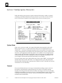
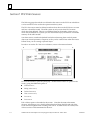
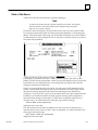
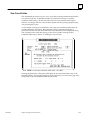
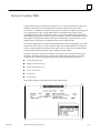
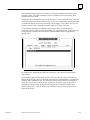
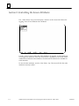
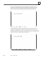
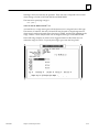
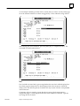
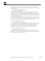
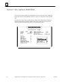
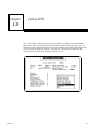
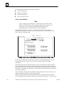
When the ADS development environment is loaded onto the ADC module, and the module
is either soft reset, or the rack the module resides in is power cycled, or the Series 90-70
PLC main rack containing the CPU module is power cycled, the ADS menu screen is
displayed. The ADS menu screen allows you to switch between running the ADS Builder
to create or modify a system and the ADS Executor to execute an existing system. This
screen also allows you to run any of the items which are currently installed. Any of the
items: ADS Builder, ADS Executor, Fault Tables, or PID may or may not be installed. If an
item is installed, ”Loaded” will be displayed next to that entry; items not installed will
have ”Not Loaded” displayed next to that entry.
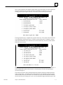
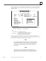
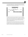
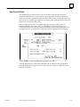
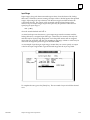
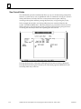
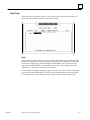
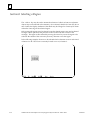
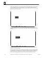
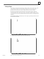
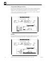
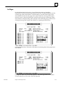
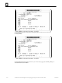
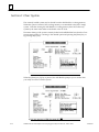
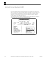
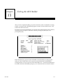
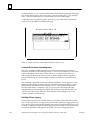
Filling-in the ADS Main Menu
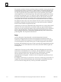
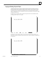
The following example is the ADS menu screen that you will interact with. Note that in
this example the ADS Builder and Executor are both shown as being Loaded.
GFK-0641
1-1
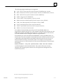
1
Required User Entries
While in this screen, you must define and make the following entries on the menu:
D
D
D
system name
terminal module
printer module
Note that these entries correspond to what must be defined by you in order to load the
ADS Execute-Only environment onto the ADC module.
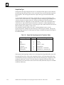
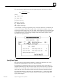
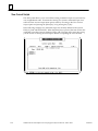
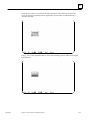
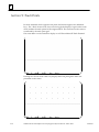
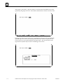
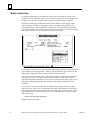
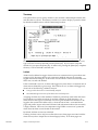
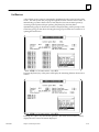
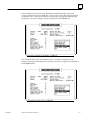
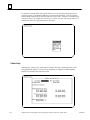
Selecting a Menu Entry
To select a menu entry to fill in, simply press the numeric key corresponding to the entry
and then press the [Enter] key. At that point the ADS menu program will prompt you
for the needed information. For example, to define a system name of PUNCH, press the
key sequence [3] [Enter].
1-2
CIMPLICITY90-ADS Alphanumeric Display System Reference Manual - March 1994
GFK-0641
1
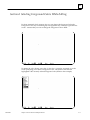
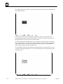
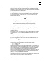
Next, at the prompt for the default system name, type in the name you have selected for
the system which in this example is PUNCH. PUNCH may either be a new or an
existing system (see Chapter 3, Section 1 for a discussion of valid system names).
Pressing the [Enter] key completes the system name entry. The system name PUNCH is
now displayed on the menu screen. Until the system name entry is changed, running
either the ADS Builder or the ADS Executor will automatically cause the system named
PUNCH to be accessed.
For a more detailed discussion of how the ADS Builder and Executor determine where to
find the indicated system, refer to Section 1, Load System, of Load/Save Operations,
located in Chapter 9.
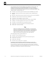
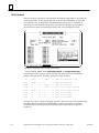
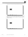
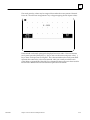
The entries for items 4 and 5 (terminal module and printer module) are filled in similar
to the system name - with the exception that entries are not arbitrarily selected; specific
defined valid entries must be made. You should choose the terminal table that matches
the one the software is being run on now, not the intended target terminal (except in the
GFK-0641
Chapter 1 ADS Main Menu
1-3
1
case of using the mini or touch mini OIT, these are generally one and the same). For
example, if you are going to access the Builder (menu choice 1) on a GE Fanuc
Workmaster II, but the target terminal is a Touch Mini, you would specify MIBM; to
execute the system on the touch mini (menu choice 2), you would specify TMINI. Valid
settings for item 4, terminal module, are:
D
D
COIT.TBL - Color GE Fanuc Operator Interface Terminal: (IC600KD512/514, 532/534);
D
D
D
D
D
D
D
D
MINI.TBL - Mini GE Fanuc Operator Interface Terminal (monochrome only): IC600KD515
MOIT.TBL - Monochrome GE Fanuc Operator Interface Terminal: (IC600KD510/513,
530/533)
TMINI.TBL - Touch mini OIT (monochrome only): IC600KD516
VT100.TBL - VT100 compatible, or superset, terminal
MIBM.TBL - Monochrome IBM compatible personal computer running TERMF
CIBM.TBL - Color IBM compatible personal computer running TERMF
TCOIT.TBL - color OptiTOUCH screen terminal from Nematron
TMOIT.TBL - monochrome OptiTOUCH screen terminal from Nematron
LUDCO.TBL - Lucas Deeco ST-2200
Note
Neither the ADS Menu Program, the ADS Builder, or the PID module
may be run on the Mini OIT. Only the execution of a system built using
another type of terminal can be run on the Mini OIT. When building a
system, you must be careful to create screens which are sized to fit
within a 15 line by 80 character display when using a Mini OIT.
The valid settings for item 5, printer module, are:
D
D
D
D
D
ASCII.TBL - Generic ASCII character printer;
TTY.TBL - Generic ASCII Teletype character printer (no form feed support);
EPSON.TBL - Epson printer;
PCNEC.TBL - NEC printer;
LA100.TBL - DEC LA100 printer (or compatible).
Specification of the .TBL extension is optional; the ADS menu program will
automatically fill in the .TBL extension for any of the entries if it is not specified.
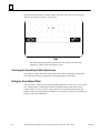
The user selections of the above items (system name, terminal module, and printer
module) are automatically saved to the file MENU.DAT on the ADC board. This allows
these options to be held across system runs and board resets.
1-4
CIMPLICITY90-ADS Alphanumeric Display System Reference Manual - March 1994
GFK-0641
1
Executor Debug Mode
The Executor may be invoked while in debug mode during the system development
cycle, if desired. Pressing the [Ctrl-X] key will cause the debug mode to toggle on/off;
when on a <debug> indicator will be displayed next to the Executor menu option. With
debug mode enabled, the Executor will display error messages at the bottom of the
display screen anytime it is unable to execute a particular command. For example,
pressing a function key to which a command to remove an alarm page is attached will
display an error message if the alarm page is not actually displayed. If debug mode is
turned off, the above situation is handled visually as a no operation (which is actually
the desired effect).
Exiting the ADS Main Menu
Exit from the ADS menu program is done by selecting item number 9. Upon exiting
(which takes 1 to 2 seconds on a Series 90-70 ADC, or 10 to 20 seconds on a Series 90-30
ADC), communications may be re-established with a computer running TERMF without
needing to hard reset the ADC module. This is particularly useful if the IBM PC-based Builder
is being used rather than the ADC - based Builder. Refer to Chapter 8, in the ADS User’s
Manual, for more detailed information on using the IBM PC-based Builder.
GFK-0641
Chapter 1 ADS Main Menu
1-5
Chapter
2
2 Introduction to Using the ADS Builder
section level 1 1
figure bi level 1
table_big level 1
The ADS Builder software allows you to create and modify a custom operator interface
system. The ADC-based ADS Builder can only be accessed through the ADS Menu
program which is only available when the ADS Development environment is installed
on the ADC module. This chapter provides a description of the major components of an
ADS system and how they tie together and interact to form a system. The steps required
to build an operator interface system are also described.
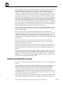
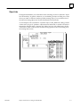
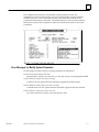
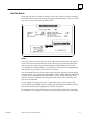
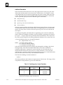
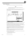
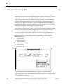
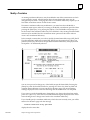
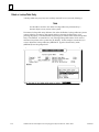
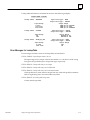
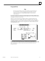
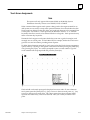
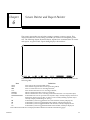
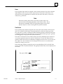
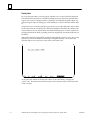
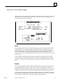
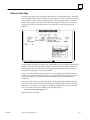
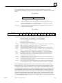
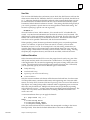
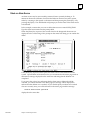
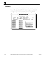
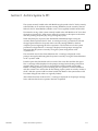
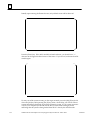
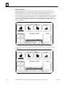
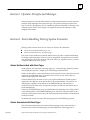
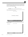
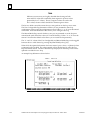
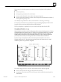
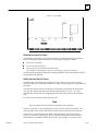
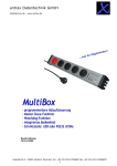
Components of an ADS System
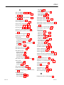
The following figure illustrates the major components and interconnections of an ADS
system. A system is composed of one or more screens. Dynamic objects may be defined
on a screen; these objects will be animated when the system is executed. Dynamic object
animation may be changing display attributes (e.g., reverse video, blue, etc.), movement,
value display or a combination of one or more attributes.
a44536
DYNAMIC
OBJECT
REPORT
LOG
TO
PRINTER ACTIONS
TRANSLATION
TABLE
PLC
DATA
PLC
DATA
SOURCE
LOOKUP
TABLE
ALARM
SOURCE
PLC
DATA
ENGINEERING UNITS
CONVERSION TABLE
DISPLAY
FORMAT
DYNAMIC
OBJECT
SCREEN
F15
F1
COMMAND
SCRIPT
ALARM
PAGE
ACTIONS
Figure 2-1. ADS System - Major Components and Interconnections
The data used to determine a dynamic object’s animation is supplied by a data source. A
data source controls the access of data from the PLC’s memory, including the type of
GFK-0641
2-1
2
data (e.g., signed word, etc.), which memory the data comes from, and how frequently it
should be gathered. Optionally, the data source’s data may be scaled. The data source
associated with a dynamic object may be changed at run time using the ATTACH
command. Translation table entries provide for linear scaling, offsetting, and data type
conversion. Lookup table entries provide for non-linear scaling and data type conversions
(e.g., signed word to string, etc.). Engineering Unit Conversion table entries provide for
converting a value to engineering units with optional data type conversion. Translation
table, lookup table, and engineering unit conversion entries may be used multiple times.
The translation, lookup or engineering unit conversion table entries associated with a
dynamic object may be changed at run time using the ATTACH command. Since a single
data source may be used to animate multiple dynamic objects, the ability is provided to
apply scaling directly to the dynamic object to support those cases where the same data
must be handled in different forms in different places in the system.
Based on a particular value, the display format provides an optional capability to affect a
dynamic object’s display attributes and movement. A display format may be used with
multiple dynamic objects.
Each screen may have up to fifteen user-defined function keys associated with it.
Pressing a function key results in some action being taken. This action may be to display
a different screen, change a value in a PLC memory, prompt the operator for some
action, etc. A command script can be attached to a function key when multiple actions are
desired as the result of a single key being pressed. A single command script may be used
multiple times.
Reports are very similar to screens, except that no function keys are provided and
dynamic object animation is restricted to value display. Reports are used to output
formatted information to a printer.
An alarm source controls the access of data from the PLC’s memory for the purpose of
detecting a transition of the data into one of up to four predefined alarm ranges. When
a particular alarm source transitions into an alarm state, a number of options may be
specified.
The occurrence of the alarm may be logged to a printer, including a timestamp of when
it occurred. One or more actions (e.g., display a new screen, issue a report, etc.) may be
triggered; a command script may be used for defining multiple actions. Alarms may also
be logged to one or more alarm pages. Alarm pages provide a mechanism which allows
you to view and optionally acknowledge alarms.
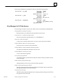
Entering the ADS Builder Program
Two versions of the ADS Builder program are available; the ADC version and an IBM PC
version.
You are strongly encouraged to use the PC-based Builder whenever possible as you will
typically find it easier to use overall. Refer to chapter 8 in the ADS User’s Manual,
GFK-0499, for details on the most efficient ways to use the PC-based Builder. Before
using the ADC-based Builder you should refer to the section under the heading
”Managing the Builder’s Memory” later in this chapter. That discussion will also refer to
the file README.401 which can be found in the \PCOP\ADS.PCM directory of the hard
disk on which you installed the ADS software.
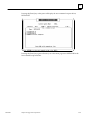
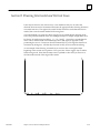
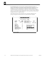
Throughout this chapter comments specific to the IBM PC version will be added. When
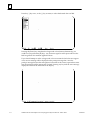
either version of the Builder is first entered a copyright screen is displayed. While this
2-2
CIMPLICITY90-ADS Alphanumeric Display System Referemce Manual - March 1994
GFK-0641
2
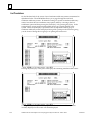
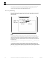
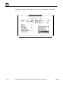
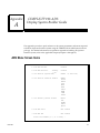
screen is displayed, in order to proceed with the Builder, you must press the [Enter] key.
After the [Enter] key is pressed the following main menu screen will be displayed (for
the ADC version).
To access the IBM PC-based Builder, issue the following command at the DOS prompt:
ADSBUILD <system_name>
(<system_path>)
where:
<system_name> is a valid ADS system name
(1-5 alphanumeric and underscore characters).
<system_path> is the optional complete path specification
for where the ADS system may be found.
If the <system_path> specification is not provided, the system will be loaded in a
PCM-compatible folder of the same name as the system, beneath the \ADS_PC directory
(the folder will automatically be created if it does not exist).
Note
It is recommended that each system be kept in a separate PCM folder.
This will be done automatically by the system if you do not specify the
<system_path> parameter. Refer to Chapter 8 in the CIMPLICITY
90-ADS Alphanumeric Display System User’s Manual, GFK-0499, for
more details.
Note
See Chapters 8 and 11 in the CIMPLICITY 90-ADS Alphanumeric
Display System User’s Manual, GFK-0499, for information on using the
Operator Interface Products Menu to access the PC-Based Builder.
GFK-0641
Chapter 2 Introduction to Using the ADS Builder
2-3
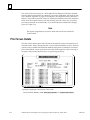
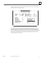
2
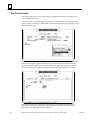
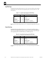
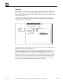
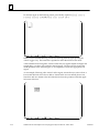
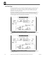
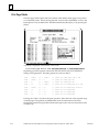
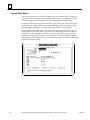
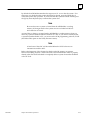
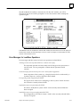
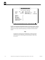
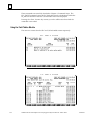
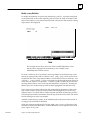
For the IBM PC-based version, the following main menu screen will be displayed.
Choosing Items From a Menu
The ADS Builder is organized as a simple pick and choose menu system. When a menu
is displayed you can either use the [ ] and [–] keys to select the desired option and then
press the [Enter] key, or you can press the key corresponding to the first character of the first
word of the desired menu option.
In some cases the selection of a menu option will result in another menu of additional
options being displayed. This menu will appear as a separate box or window which will
overlay the current menu. When this happens, it indicates that you have progressed
down a level in the menu tree. In other cases the selection of a menu option will result in
the display of a data entry form which you will need to fill out. On data entry forms you
proceed from field to field by either pressing the [–] or [Enter] key to select the next field
or by pressing the [ ] key to select the previous field. Pressing the [Enter] key when the
last field of a form is selected will complete the form.
Note that the [Enter] key may be labeled [Return] on some keyboards; for keyboards with a second
[Enter] key located in the numeric keypad area, only the [Enter] key located with the QWERTY
keys should be used. Pressing the <Save> key from any field immediately
completes the form (if all required fields have been filled in). The <Quit>
key may be used to return to a higher menu level or to abort the data entry
form.
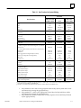
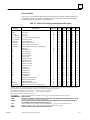
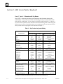
Use of [ ] and < > Characters with Key Names
The [ ] and < > character pairs have special meaning in this document when used to
indicate keys.
If a key name is enclosed in brackets ([ ]) the key is actually labeled with that name on
the keyboard. If a key name is enclosed by angle brackets (< >) the key’s location on
the keyboard must be determined from the following table. When using this table be
sure to use the column that matches your terminal type (based on terminal selection that
you made on the menu program screen described in Chapter 1).
2-4
CIMPLICITY90-ADS Alphanumeric Display System Referemce Manual - March 1994
GFK-0641
2
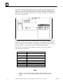
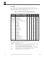
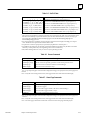
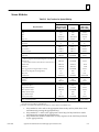
Table 2-1. Key Functions for System Building
Terminal
MOIT/COIT
TMOIT/TCOIT
MIBM/CIBM†
VT100
MPC/CPC
EIBM/VIBM‡
GOLD
F11
PF1
Insert
Help
F12
PF2
Home
Quit
F10
KP0
Esc or F10
Save
GOLD F10
Key Function
Object list
GOLD KP0
Alt-F10
GOLD S
GOLD S
Alt-S
Refresh screen
^W
^W
^W
Clear field
^X
^X
^X
Beginning of line
GOLD ←
GOLD ←
GOLD ←
End of line
GOLD →
GOLD →
GOLD →
Top of screen
GOLD ↑
GOLD ↑
GOLD ↑
Bottom of screen
GOLD ↓
GOLD ↓
GOLD ↓
Video select
F1
KP1
F1
Video clear
GOLD F1
GOLD KP1
Alt-F1
Color
Black, red, green, Yellow, Blue, Magenta, Cyan, White
F4
KP4
F4
Character set
Normal, Alternate Set, Character Set 2, Character Set 3
GOLD F4
GOLD KP4
Alt-F4
Double wide
GOLD W
GOLD W
Double size
GOLD D
GOLD D
Draw toggle (non-rectangular objects or lines)
GOLD F5
GOLD KP5
Draw area (rectangular and straight lines)
F5
KP5
F5
Delete line
F14
PF4
End
Undelete line
GOLD F14
GOLD PF4
GOLD End
Select toggle
F3
KP3
F3
Cut area
F6
KP6
F6
Paste area
GOLD F6
GOLD KP6
Alt-F6
Startdynamic/predefinedobject
GOLD F7
GOLD KP7
Alt-F7
F7
KP7
F7
End predefined objects
GOLD F2
GOLD KP2
Alt-F2
Delete dynamic object
GOLD F8
GOLD KP8
Alt-F8
Modify dynamic object
F8
KP8
F8
Copy dynamic object
F9
KP9
F9
Paste dynamic object
GOLD F9
GOLD KP9
Alt-F9
End dynamic object
Touch screen grid
Touch screen assignments
Alt-W
Alt-D
Alt-F5
F13
PF3
Delete
GOLD F13
GOLD PF3
GOLD Delete
† Num Lock must be set to OFF for 83-key keyboard; F11 and F12 keys on the enhanced AT and PS/2 style keyboards
cannot be used (use SHIFT-F1 and SHIFT-F2).
‡ The MPC, CPC, EIBM, and VIBM terminal tables are used for the PC-based Builder only.
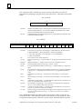
1.
2.
3.
GFK-0641
Keys marked as Alt-x refer to the appropriate alternate key (Alt key held down while
simultaneously pressing the appropriate key).
Keys marked as ^x refer to the appropriate control key (Ctrl key held down while
simultaneously pressing the appropriate key).
Keys marked as GOLD xxx refer to the two-key sequence of the GOLD key followed
by the appropriate key.
Chapter 2 Introduction to Using the ADS Builder
2-5
2
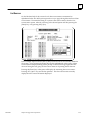
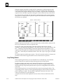
Managing the Builder’s Memory
The ADS Builder makes all changes to a system in a work space, not affecting the
original system until the changes are saved. Screens and reports, due to their size, are
only loaded into the work space when you reference them. As more and more screens
and reports are created and/or modified, the ADS Builder may run out of memory in its
work space to make any additional changes. In the ADC-based Builder, available
memory is displayed at the top of the screen next to the entry Memory:. Two numbers
are shown. The first number indicates the total bytes remaining unused on the ADC
module and the second indicates the size of the largest contiguous block of bytes
remaining unused. If insufficient memory is available, an error message will be
displayed informing you of the situation.
It is recommended that as you see total available memory shrink to below 60,000 bytes
or the largest block available shrink below 25,000 bytes, the system be saved to avoid the
potential loss of subsequent changes. In saving a system the ADS Builder empties its
work space of all screens and reports, thereby freeing up memory to allow you to
continue.
In addition, it is good practice to make frequent saves of the ADS Builder’s work space to
minimize the potential loss of data due to a power failure. Periodic archives of a system
to a host computer is also recommended.
Additional information concerning managing the memory of the ADC module can be
found in the file \PCOP\ADS.PCM\README.401 which was installed on your
computer ’s hard disk as part of the ADS installation procedure.
Errors Loading Screens and Reports
Caution
The ADS Builder does NOT check to see if items such as display
formats and command scripts are used anywhere in the system prior to
performing a user directed delete operation for one of those items.
Precautions should be taken to make sure that an item is not
referenced any longer before deleting it.
If such a situation occurs, attempting to load a screen or report referencing the deleted
item will result in an error message such as Error loading ... or Error verifying ... the
given screen or report file. For example, if you attempt to access such a screen via the
Screen paint submenu option on the Screen operations menu, an error message will be
displayed and you will not initially be allowed into the screen/report editor. However,
the ADS Builder will show the screen as being loaded into its working memory (an
asterisk (*) character will be displayed to the right of the screen number in the status
area). Attempting to access the screen/report editor a second time for that screen will
succeed. Be sure to check all function key assignments and dynamic object definitions to
look for references to a previously deleted item. If a problem is found either the
offending references must be deleted or the item recreated to correct the problem.
2-6
CIMPLICITY90-ADS Alphanumeric Display System Referemce Manual - March 1994
GFK-0641
2
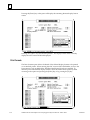
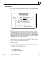
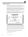
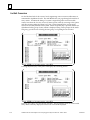
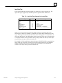
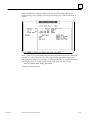
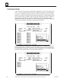
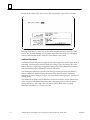
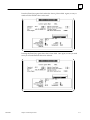
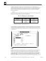
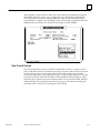
Object Lists
Throughout the Builder you will be able to take advantage of what is called the ”object
list” functionality. In general, whenever you are defining an object or filling out a form
where you need to reference another, possibly existing, object, you can obtain a list of
the relevant existing objects and choose the desired one from the list.
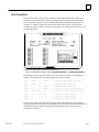
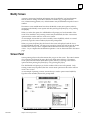
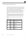
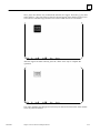
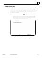
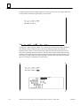
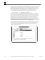
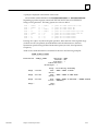
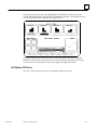
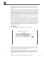
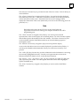
As an example, in the screen below a dynamic object, CART_DISPLAY, is being created.
A data source (a type of ”primitive” object) must be referenced or created to be used to
animate the dynamic object. Pressing the <object list> key with a blank entry for the
”Data Source” field would result in a window being opened on the screen listing all of
the existing data sources.
GFK-0641
Chapter 2 Introduction to Using the ADS Builder
2-7
2
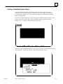
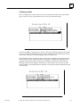
Alternatively, if you knew that the data source you wished to reference began with the
letter ”C”, you could type that letter into the ”Data Source” field prior to pressing the
<object list> key. The same window would be opened on the screen, but this time only
those data sources beginning with the letter ”C” are listed. The option of creating a new
data source is also provided.
The [ ] and [–] keys can be used to scroll through the list of objects; the object currently
displayed in reverse video is called the current object. Pressing the [Enter] key selects
the current object for use; the window is automatically closed when an entry is selected.
Pressing the <Quit> key closes the window without selecting any object.
The keys that are available when an object list window is open on the screen are
summarized in the table below.
Key
Function
↑
previous entry
↓
next entry
<GOLD> ↑
previous page of entries
<GOLD> ↓
next page of entries
<GOLD> [T]
top of list
<GOLD> [B]
bottom of list
[Enter]
select current entry and close window
<Quit>
close window with no entry selected
Note
Extensive context sensitive help is available in the ADS Builder. Use the
<HELP> key to access the help information related to any point in the
builder.
2-8
CIMPLICITY90-ADS Alphanumeric Display System Referemce Manual - March 1994
GFK-0641
Chapter
3 Configuration Operations
3
section level 1 1
figure bi level 1
table_big level 1
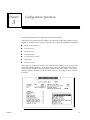
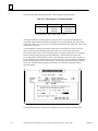
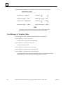
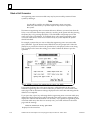
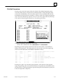
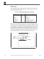
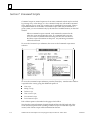
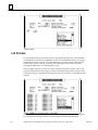
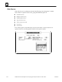
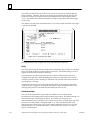
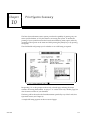
This chapter describes the Configuration operations submenu.
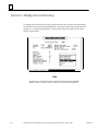
When the Configuration operations submenu is selected, the following example screen is
displayed. Another menu window is opened on the screen, giving additional options of
D
Modify system parameters
D
PLC data sources
D
Display formats
D
Translation table
D
Eng unit conversion table
D
Lookup table
D
Command scripts
This chapter is divided into sections, with each section describing one of the options for
the Configuration Operations. Note that in most cases, only the initial screen will be
shown for each submenu since the general format for each one is similar. Each of the
options from each submenu will be described in the text. Any unique screens will also
be shown.
GFK-0641
3-1
3
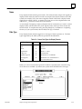
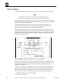
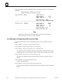
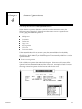
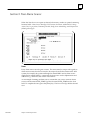
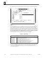
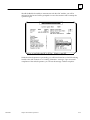
Section 1: Modify System Parameters
When the Modify system parameters option is selected, a data entry window is opened
containing seven fields which may be set by the user: System Name, Terminal, Terminal
Device, Printer Device, Default Scan rate, Default Alarm Scan rate, and Startup screen.
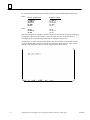
System Name
When a new system is created, it is assigned the default name specified on the ADS
Menu program screen. A system name can be from one to five alphanumeric and
underscore ( _ ) characters in length; the name is NOT case sensitive. The system name
is used in the generation of the names of the files making up the system; a unique name
relevant to your application should be used for a new system. If a non-unique system
name is chosen, the ADS software will NOT warn you of that fact; the original system
will be irretrievably lost when a subsequent system save operation is performed. The
next example screen assumes that the system name is set to DRILL.
To set the system name type in the desired name of the system, DRILL, overwriting the
default name in the reverse video block. To complete the entry, press the [Enter] key.
Note that after the [Enter] key is pressed the next field, Terminal, is selected next (reverse
video block is now on this field).
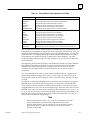
Terminal
The terminal field indicates on what type of terminal the resulting system is to be run.
By default it will indicate the same terminal type on which it is currently running.
Typically, the setting of this field will never need to be changed. However, it is possible
to build a system while connected to one type of terminal and then run the system while
connected to a different type. In such a case, you would enter the name the target
terminal in the terminal field.
3-2
CIMPLICITY90-ADS Alphanumeric Display System Reference Manual - March 1994
GFK-0641
3
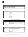
The following target terminal types are supported:
D
D
D
D
D
D
D
D
D
D
COIT - Color GE Fanuc Operator Interface Terminal: (IC600KD512/514, 532/534);
MOIT - Monochrome GE Fanuc Operator Interface Terminal: (IC600KD510/513, 530/533);
MINI - Mini GE Fanuc Operator Interface Terminal: IC600KD515;
TMINI - Touch mini OIT: IC600KD516;
VT100 - DECt VT100 compatible, or superset, terminal;
MIBM - Monochrome IBM compatible personal computer running TERMF);
CIBM - Color IBM compatible personal computer running TERMF;
TCOIT - OptiTOUCH (color touch screen from Nematron);
TMOIT - OptiTOUCH (monochrome touch screen from Nematron);
LUDCO - Lucas Deeco ST-2200 terminal.
Four additional terminal tables are used by the PC-based Builder, MPC for a
monochrome computer and CPC for a color computer using the ASCII character set, and
EIBM (EGA adapter) and VIBM (VGA adapter) for a computer using the OIT character
set. These should always be changed to reflect the target terminal.
The terminal type is never checked by the ADS Builder - only by the ADS Executor. If
the Executor is run and a mismatch is detected between the attached terminal and what
is indicated by the terminal field of the loaded system, the Executor will warn you of
that fact but then continue to execute the system. For example, if a system is built
specifying the use of a COIT terminal, but is then executed specifying a VT100 terminal,
the message
Terminal mismatch - using user specified VT100 rather than COIT terminal ...
would be displayed on the attached terminal. The system will execute correctly,
although some terminal specific features such as foreground and background color
selections may be lost.
t DEC is a trademark of Digital Equipment Corporation
GFK-0641
Chapter 3 Configuration Operations
3-3
3
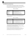
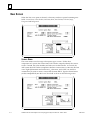
Terminal Device
The Terminal Device field indicates to which port on the ADC the terminal is to be
connected when the system is actually executed. By default, this field is set to COM2:,
which stands for serial communications port 2. COM1: may be selected if the terminal is
to be connected to serial communications port 1. A third choice, STDIO:, allows the
terminal to be connected to whichever port is specified for the target terminal in the
ADS Setup Utility, without actually specifying it as part of the system definition.
When you cursor onto the Terminal Device field, a window is opened on the screen
showing what choices are available.
For the COIT terminal, COM2: is the correct choice; press the [Enter] key. The next field,
Printer Device, is then selected.
3-4
CIMPLICITY90-ADS Alphanumeric Display System Reference Manual - March 1994
GFK-0641
3
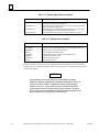
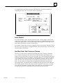
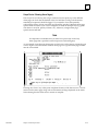
Printer Device
Printer output is directed to the device specified by the Printer Device field. The
following devices are supported: COM1:, COM2:, PC:, RAM: and NULL:. COM1: and
COM2: have the same meanings as discussed above for Terminal Device. If PC: is
selected, printer output will be directed to a file named SPOOLER.LOG in the current
folder on an attached PC (which must be running TERMF). The printer file will be
opened when the Executor begins running the system, and will be closed whenever the
Executor is exited. The RAM: selection is similar to PC: except that the file is opened on
the ADCs RAM disk. If printer output is not to be supported, NULL: is selected. Any
subsequent printer output will be lost with NULL: selected as the printer device. By
default the printer device is set to NULL: (no printer output).
When you cursor onto the Printer Device field, a window is opened on the screen
showing what choices are available (choices as mentioned above). Assume that you
wish to change the printer device from NULL: to COM1:. To select the desired choice,
press the [–] key twice (or the [ ] key three times). COM1: will now be highlighted by
the reverse video block.
To complete the selection, press the [Enter] key. The selected choice, COM2:, is now
filled in as the printer device and the next field, Default Scan Rate, is selected.
Default Scan Rate
All data sources (memories in the PLC) are scanned at a given synchronous rate. Each
source can be scanned at a specific rate or the default system scan rate. This field might
be edited several different times while a running system is tuned to request its data as
infrequently as possible while still providing an acceptable update rate (every time the
ADC requests data from the PLC the scan time is affected by several milliseconds).
As a default, the system scan rate is set up for every 1.0 second. This value may be
changed, in increments of 0.25 seconds, to any value within the range 0.25 to 9999.75
seconds.
GFK-0641
Chapter 3 Configuration Operations
3-5
3
Default Alarm Scan Rate
All alarm sources (memories in the PLC) are scanned at a given synchronous rate. Each
source can be scanned at a specific rate or the default system alarm scan rate. This field
may also be edited several different times as the running system is tuned to request its
data as infrequently as possible while still providing an acceptable update rate (every
time the ADC requests data from the PLC the scan time is affected by several
milliseconds). As a default, the system alarm scan rate is set up for every 1.0 second. This
value may be changed, in increments of 0.25 seconds, to any value within the range 0.25
to 9999.75 seconds.
Note
It is possible, particularly with the Series 90-30 ADC, to select a scan rate
too small for the amount of data specified to be gathered. In such a case,
the ADS Executor will attempt to ”self-regulate” itself to slow down the
requests to a rate it can keep up with. It is possible, however, that in
conjunction with keyboard input screen response may appear to
temporarily ”freeze”. Slowing down scan rates can alleviate this
situation.
Startup Screen
The Startup Screen field designates which screen of the possibly multiple screens making
up a system is to be displayed first when the Executor is run. This number can be any
legal screen number, ranging from 1 to 999. By default this field is initialized to 0, which
allows you to specify the required startup screen at run time. A starting screen may not
be specified until the screen actually exists. If the Modify System Params data entry
screen is exited without specifying a starting screen number (which you must do if the
starting screen has not been created yet), the ADS Builder displays the warning message
Warning - no startup screen yet specified
on the message line at the bottom of the screen. Prior to running the system via the
Executor, a startup screen should be specified.
3-6
CIMPLICITY90-ADS Alphanumeric Display System Reference Manual - March 1994
GFK-0641
3
This completes the selections on the Modify system parameters screen. The
modifications you have made must be saved. To exit the Modify system parameters
submenu press the <Save> key from any field or the [Enter] key with the cursor
positioned on the Startup Screen field. The modifications are saved and the summary
information on the screen is updated to reflect the modifications made to the system
parameters.
Error Messages for Modify System Parameters
Error messages and their causes for system parameters are listed below.
Cannot load terminal table XXXXX.TBL
Terminal table ”XXXXX” does not exist; you can only specify an existing terminal table.
ENTRY ERROR :: Default scan time is too large
A default scan rate greater than the maximum supported has been entered.
ENTRY ERROR :: Default alarm scan time is too large
A default alarm scan rate greater than the maximum supported has been entered.
ENTRY ERROR :: Startup screen does not exist
You cannot reference a startup screen that does not exist.
GFK-0641
Chapter 3 Configuration Operations
3-7
3
Section 2: PLC Data Sources
The following pages describe how to define the data sources in the PLC from which data
is to be read that is to be used in the operator interface system.
The PLC data sources must be defined to indicate from where in the PLC data is to come
and how it should be treated. The ADS system can only access those PLC locations
which have been defined. There is no predefined limit on the number of data sources
which may be defined for a system; you are constrained only by the amount of available
memory on the ADC module.
Your data sources can either be defined here before referencing them with a dynamic
object (see Screen Operations, Chapter 4), or they can be created from within the Screen
Painter when you are creating a dynamic object.
In order to access the PLC data sources submenu, cursor to that menu selection.
To access the submenu, press the [Enter] key. Another menu window is opened on the
screen, giving the additional options of
D
D
D
D
D
D
New data source;
Modify a data source;
Delete a data source;
View current sources;
List sources;
Print sources
Each of these options is described in this section. Note that the status information
(Screens:, Alarm Pages:, etc.) which had been displayed along the left hand side of the
screen has been replaced with a heading Data Sources. As data sources are created, a list
of those sources will be maintained in this area.
3-8
CIMPLICITY90-ADS Alphanumeric Display System Reference Manual - March 1994
GFK-0641
3
New Data Source
When the New data source option is selected, a data entry window is opened containing
five fields which may be set by entering the appropriate information: Name, Source Data
Type, Source Location, Scan Rate and Additional Calc.
Name
Every PLC data source must be given a name. This name must be unique with regards
to PLC data source names, but does not need to be unique from all other names in the
ADS system (for example, the system itself might be named DRILL and a PLC data
source might also be named DRILL). A name may be from one to twelve alphanumeric
and underscore (_) characters, and is NOT case sensitive.
It is recommended that you choose names which reflect the meaning of the data which
will be retrieved. For example, the names PARTS_COUNT, TEMP_SETTING and ESTOP
are much more meaningful than the names REG1 or XYZ. A little forethought in the
selection of names will make the resulting system much more self-documenting, and
thus more maintainable.
As an example of creating a data source - assume that the you wish to create a data
source with the name PARTS_COUNT. Simply type the desired name PARTS_COUNT
into the Name field which is highlighted by a reverse video block.
To complete the entry press the [Enter] key. Note that after the [Enter] key is pressed
the next field, Source Data Type, is selected next (reverse video block is now on this field).
GFK-0641
Chapter 3 Configuration Operations
3-9
3
Source Data Type
Every data source must be tagged to indicate what type of data it represents. The data
types supported by the ADS system are specified in the table below.
Table 3-1. Source Data Type Supported for Data Sources
Data Type
Size (Bits)
Value Range
State
1
OFF, ON
Byte
8
0 to 255
Word
16
0 to 65535
Signed Word
16
–32768 to +32767
Longword
32
0 to 4294967295
Signed Longword
32
–2147483648 to +2147483647
Floating Point
32
–999999999.9 to +9999999999.99 †
† Only 7 digits of precision.
Selecting a Source Data Type
When you cursor onto the Source data type field another window is opened on the screen
showing the available choices for data type. By default, the system selects WORD for
the source data type.
Use the [ ] and [–] keys to select the data type choice which matches the type of data in
the PLC represented by the data source. To complete the selection press the [Enter] key
after you have cursored to the desired data type source. After the [Enter] key is pressed
the next field, Source Location, is selected next (reverse video block now on this field).
3-10
CIMPLICITY90-ADS Alphanumeric Display System Reference Manual - March 1994
GFK-0641
3
Source Location
The Source Location field is used to attach a data source to a specific location (reference),
or multiple locations, in the PLC. Memory locations in the PLC that are supported by
the ADS system are specified in the table below.
Table 3-2. Series 90 PLC References Supported by ADS System
PLC
Memory
DATE
TIME
PLC_ID1
PLC_STATUS
PLC_ACCESS
PLC _SWEEP
RACK_mm
SLOT_mn
BUS_mno
M_mnopp
R
AI
AQ
I
Q
M
T
S
SA
SB
SC
G
GA
GB
GC
GD
GE
^P 2
^L 3
Z
MEMORY
MAX_BLOCK
Description
PLC Date
PLC Time
PLC ID
PLC Status
Control Program/P
rivilegeLevel
Last Sweep Time
Fault in Rack mm
Fault in Rack m, Slot n
Fault in Rack m, Slot n, Bus o
Fault in Rack m, Slot n, Bus o, Module pp
Registers
Analoginputs
Analogoutputs
Discrete inputs
Discrete outputs
Internal coils
Temporary coils
Special contacts
Special contacts A
Special contacts B
Special contacts C
Global data
Global data A
Global data B
Global data C
Global data D
Global data E
Main program block data
Sub program block data
ADS internal data
ADS internal free memory
ADS internal free memory, largest block
Size/
Reference
32
32
n/a
16
16
16
1
1
1
1
16
16
16
1
1
1
1
1
1
1
1
1
1
1
1
1
1
16
16
16
32
32
Over Diags Slice
N
N
N
N
N
N
N
N
N
N
N
Y
N
N
Y
N
N
N
N
N
N
N
N
N
N
N
N
N
N
N
N
N
Y
N
Y
Y
N
Y
Y
Y
Y
N
Y
Y
N
Y
N
N
N
N
N
N
N
N
Y
N
N
Y
N
N
Y
N
N
Y
N
N
Y
N
N
Y
N
N
Y
N
N
Y
N
N
Y
N
N
N
N
Y
N
N
Y
N
N
Y
N
N
N
N
N
N
Ref
N
N
N
N
N
N
N
N
N
N
Y
Y
Y
Y
Y
Y
Y
Y
Y
Y
Y
Y
Y
Y
Y
Y
Y
Y
Y
Y
N
N
Write
N
N
N
N
N
N
N
N
N
N
Y
Y
Y
Y
Y
Y
Y
N
Y
Y
Y
Y
Y
Y
Y
Y
Y
Y
Y
Y
N
N
1The PLC_ID is a 1 to 7 character string which contains the identifier name of the PLC CPU. It is a special case where the data type is
forced to be BYTE within the ADS Builder yet requires an XXXXXXX field picture in the painter.
2The full syntax for Main Program locations is : <program_name>^P<address>.
3 The full syntax for Sub Program locations is : <block_name>^L<address>.
4The parameters listed in this table are as follows:
PLC Memory
Size/Reference
Over
Diags
Slice
Ref
Write
GFK-0641
Refers to the identifier used in the <location_type> field of the location reference syntax.
Data size in bits.
Is there an override bit associated with the location type? Override bits are specified by using ”O” in the
<modifier> field of the location reference syntax.
Is there a diagnostic bit associated with the location type? Diagnostic bits are specified by using ”F” in
the <modifier> field of the location reference syntax.
Indicates whether it is possible to specify individual bits, or groups of bits from the location.
Indicates whether it is necessary to provide an address for the location type.
Indicates whether a value can be written to the location.
Chapter 3 Configuration Operations
3-11
3
PLC_ACCESS and PLC_STATUS are ”special” locations that allow you to look at
individual bits pertaining to program access and system status. These bits are described
below.
PLC_ACCESS
0
7 8
15
CP Num
Priv Lev
CP Num
Indicates the number of the Control Program to which the requesting device is attached. Possible values are -1 to 7, where -1 indicates not attached to any control
program. This number is always 0 for Series 90-30.
Priv Lev
Current privilege level of requesting device for accessing memory in the PLC CPU
(valid entries are 0 through 4).
PLC_STATUS
15
14
13
12
PLC State
PLC State
11
10
9
8
7
6
5
4
3
2
1
0
N
U
Prg
chg
OEM
prot
Run
SW
IO
SW
Prg
Att
IO
flt
PLC
flt
IO
chg
PLC
chg
Con
Swp
Ovr
Swp
Current State (as opposed to switch settings or commanded state). Possible values are:
0 - RUN_ENABLED; 1 - RUN_DISABLED: 2 - STOP_IO_DISABLED
3 - CPU_STOP_FAULTED; 4 - CPU_HALTED; 5 - CPU_SUSPENDED
6 - STOP_IO_ENABLED
NU
Not used (reserved for future expansion).
Prg chg
Program changed flag: 1 = Program change; 0 = No program change (90-70 rel 2.X and
later).
OEM prot
OEM protected flag: 1 = OEM protection in effect; 0 = No OEM protection.
Run SW
Front panel RUN/STOP switch setting; 1 = RUN; 0 = STOP.
IO SW
Front panel ENABLE/DISABLE switch setting: 1 = Outputs Disabled; 0 = Outputs Enabled.
Prg Att
ProgrammerAttachment flag. Shows whether or not there is a programmer attachment
in the system. 1 = Programmer attachment found; 0 = No programmer attachment
found.
I/OFault Entry present flag; 1 = Fault entry in I/O fault table; 0 = I/O fault table is
empty.
IO flt
PLC flt
PLC Fault Entry present flag: 1 = Fault entry in PLC fault table; 0 = PLC fault table is
empty.
IO chg
I/OFault Entry changed flag: 1 = I/O fault table has changed since last read by this device; 0 = I/O fault table same as when last read.
PLC chg
PLC Fault Entry changed flag: 1 = PLC fault table has changed since last read by this
device; 0 = PLC fault table same as when last read.
Con Swp
Constant sweep mode setting: 1 = Constant sweep mode enabled for current control
program; 0 = Constant sweep mode not enabled.
Ovr Swp
Oversweep flag (if constant sweep mode enabled). Shows whether the constant sweep
value was exceeded on the last sweep. 1 = Constant sweep value was exceeded; 0 =
Normal sweep.
The Z, MEMORY, and MAX_BLOCK locations are internal to ADS; i.e., they are not
present in the PLC. There are 1024 references in Z memory, Z1 through Z1024. These
are typically used for special ”interlocks” in your system. The demonstration systems
3-12
CIMPLICITY90-ADS Alphanumeric Display System Reference Manual - March 1994
GFK-0641
3
provided with the product have a number of examples that show how Z memory can be
used. MEMORY returns the number of free (unallocated) bytes of memory left on the
ADC module while the Executor is running. It is useful while you are developing your
system to monitor the maximum runtime memory usage. You should specify a source
data type of LONGWORD. Any dynamic object referencing a data source whose PLC
location is MEMORY should allow for up to a 6-digit number. You may need to monitor
memory usage on multiple screens since memory ”shrinks” and ”expands” as screens are
pushed and popped. Also, alarm logging continually shrinks memory until alarms are
acknowledged. MAX_BLOCK functions identically to MEMORY, except that it returns
the size (in bytes) of the largest contiguous block of free (unallocated) memory.
The typical information which you must type in to specify a source location is:
<source location> ::= <PLC memory> <reference> (: <modifier>)
where <PLC memory> is as listed in the table above and <reference> is a numeric
value specifying a particular reference offset within the PLC memory. Optionally, a
reference <modifier> may be specified for some PLC memory types, where O indicates
the reference’s override status and F indicates its point/channel fault status.
For example, to indicate a source location for PLC memory reference %R1, you would
specify R1. The previous field, Source Data Type, determines how many consecutive
references are implied by the source location selection. For example, if a source location
of I1 were specified along with a source data type of WORD, the data source would
include PLC memory locations %I1 to %I16. The reason for this is that the WORD data
type requires sixteen bits of storage and that each %I reference is a single bit in size.
As an example of a source location entry, assume that you want to attach the data source
to PLC reference %R1. To do this - type R1 into the Source Location field. Note that for
this example only %R1 is referenced since the data type WORD requires sixteen bits of
storage and each %R reference is sixteen bits in size. To complete the entry, press the
[Enter] key. Note that the next field, Scan Rate, is selected next.
Not all source locations can be specified as simply as in the example above. At times you
may only be interested in part of the data stored in a PLC memory location. In other
cases you may need to construct a source location for non-consecutive bits of storage in
the PLC. In still other cases you may only be interested in a subset of a group of bits of
storage in a PLC. To support those situations the following more complicated grammar
is supported,
<bit reference
::= <bit offset> (-<bit offset>)
<reference subset>
::= [<bit reference> 0{, <bit reference>}]
<PLC memory reference
::= <PLC memory> <reference> (:<modifier>)(reference
subset>)
<Source location>
::= <PLC memory reference> 0{; <PLC memory reference>)
where <PLC memory>, <reference> and <modifier> are as defined above, <bit
offset> is a starting bit position within this location, -<bit offset> is the upper limit of a
range of bits, <bit offset> indicates a further bit position and; <PLC memory
reference> indicates that multiple locations can be defined.
Source locations are evaluated left to right, building up the required data from the least
significant bit to the most significant bit. The total number of bits specified must be less
than or equal to the number of bits implied by the source data type. Some examples are
given below which should help clarify the grammar.
GFK-0641
Chapter 3 Configuration Operations
3-13
3
Assume that you wish to access a WORD of data which is located across the upper byte
of %R1 (low byte of WORD) and the lower byte of %R2 (high byte of WORD). This
could be accomplished by specifying a source location of
R1[8-15];R2[0-7]
Assume that there are a set of 16 boolean flags in PLC word memory location %AI6, and
you want to access the sixth flag beginning with the least significant bit (bit b5). For this
example, assume that you have already specified a source data type of STATE. The
source location would be specified as
AI6[5].
Assume that you are only interested in the lower order twelve bits of PLC word memory
location %AQ2; it is possible that the upper four bits are not zero. Also assume that you
have already specified a source data type of WORD. The source location would be
specified as
AQ2[0-12].
Assume that you wish to compose a word value where bit b0 is from %M1, bit b1 from
%I5, bit b2 is from bit b3 of %R123, bits b3 - b5 are from bits b13 through b15 of %R123
and bit b6 is from %T7. In this case you have already specified a source data type of
WORD. The source location would be specified as
M1;I5;R123[3,13-15];T7.
Assume that you wish to access the override indicator for %I12. In this case you would
specify a source data type of STATE, and the source location as
I12:0
Assume that you wish to access the current date as maintained in the PLC. You would
specify a source data type of LONGWORD and a source location of
DATE
Assume that you wish to access the PLC ID as configured in the PLC. You would specify
a source data type of BYTE and a source location of
PLC_ID
Assume that you wish to access the fault indicator for the Genius block configured as
block 27 located on bus 1 of the Genius Bus Controller located in slot 5 of rack 1. You
would specify a source data type of STATE and a source location of
M_15127
Assume that you wish to access the PLC state information from the PLC status word.
You would specify a source data type of WORD and a source location of
PLC_STATUS [12-15]
As you can see from the above examples, very complicated source locations may be
specified. When specifying these source locations, you must take care, however, that data values
are specified in the correct bit order. If they are not in the correct order, erroneous data will
be gathered and displayed. The ADS system assumes that you are correctly specifying
what is really desired, but you must tell it what you actually want.
3-14
CIMPLICITY90-ADS Alphanumeric Display System Reference Manual - March 1994
GFK-0641
3
Scan Rate
The Scan Rate field defines the synchronous rate at which the ADS system will gather
data from the PLC defined in the Source Location field. By default, this field is set to *,
indicating that the data should be gathered at the system default scan rate (see Modify
System Parameters, Default Scan Rate, earlier in this section). This setting should be
changed only if you wish to guarantee a given scan rate regardless of the default setting.
The format for defining a specific scan rate is
HH:MM:SS.CC
where HH refers to hours, MM to minutes, SS to seconds and CC to hundredths of a
second.
Any time between 00:00:00.01 and 99:59:59.99, inclusive, may be entered. The ADS
system’s basic time element is 0.25 second; because of this, the ADS system will round all
times up to the nearest 0.25 second. This means that the fastest rate which can be
specified is 00:00:00.25, and the slowest 100:00:00.00.
When specifying a time, the entire specification must be given, not just the significant
portion. For instance, to specify a scan rate of 3 seconds, you must enter 00:00:03.00, not
just 3 or 3.00.
As an example of entering a new scan rate, assume that your system is to scan the
contents of PLC memory location %R1 every 1.5 seconds. Type the value 00:00:01.50
into the Scan Rate field. Pressing the [Enter] key completes the entry. When the [Enter]
key is pressed, the next field, Additional Calculation, is selected.
Note
If a particular data source is being used only to animate a dynamic
object on a report form, the scan rate setting will be ignored when the
system is executed. When a report is executed, all data sources
animating dynamic objects on the report form are gathered once from
the PLC. If a data source is used to animate a dynamic object on a
screen, the defined scan rate is put into effect.
GFK-0641
Chapter 3 Configuration Operations
3-15
3
Additional Calculation
Often data retrieved from the PLC is not in the proper form for use by any part of the
ADS system and may need to be converted to a usable format. For example, a counts
value might need to be converted to engineering units prior to being used by the ADS
system. The Additional Calculation field provides a method for doing this. In this field,
you can optionally specify one of four different types of calculations.
D
lookup table entry;
D
translation table entry;
D
engineering units conversion table entry;
D
custom translation.
Only the custom translation calculation will be discussed in detail here; for a discussion
of lookup table entries, translation table entries, and engineering unit conversion table
entries, see Lookup Table, Translation Table and Engineering Units Conversion Table later in
this chapter.
An existing lookup table, translation table or engineering units conversion table entry
may be referenced. Multiple calculations can be specified by separating each reference
by a space ” ” (output/input data type matches must be maintained). The <object list>
key can be used to obtain a list of existing additional calculations or to create a new one.
A custom translation allows you to apply the formula
(A * (Input Value + B) ) + C
where:
A is the scaling factor
B is the pre-scaling offset
C is the post-scaling offset
to the data retrieved from the PLC (with the data interpreted according to the Source
Data Type field). Note that the formula defined here is the same as defined for
translation table entries. In general, if a given translation is to be used only once it
should be defined in the PLC data source as a custom translation. If it is to be used
multiple times, it is better to define the actual translation only once as a translation table
entry and then reference the entry as the additional calculation.
The format for defining a custom translation is
(A,B,C)
where the parentheses and commas are required parts of the format. The range of data
acceptable for each parameter is given in the table below.
Table 3-3. Data Range for a Custom Translation
Parameter
Minimum
Value
Maximum
Value
A
–100000000
+1000000000
B
–100000000
+1000000000
C
–100000000
+1000000000
(1) Only 7 digits of precision.
(2) Maximum of 6 digits to right of decimal point.
3-16
CIMPLICITY90-ADS Alphanumeric Display System Reference Manual - March 1994
GFK-0641
3
In the example below, assume that the value retrieved from %R1 is in the range of -200
to 200, but that the ADS system needs to work on the value scaled to the range 0 to 100.
A custom translation which would accomplish this is (.25,200,0). The needed translation
is typed into the Additional Calculation field.
When you press the [Enter] key at this point, it completes not only the entry of the
Additional Calculation field, but also completes the entry of the New data source. An
informative message is displayed on the status line indicating the completion of the data
source creation.
Note that the New data source (which has just been completed), PARTS_COUNT, is now
listed in the status area of the screen (left-hand side) as an available data source.
GFK-0641
Chapter 3 Configuration Operations
3-17
3
Modify a Data Source
An existing data source may be modified in much the same manner in which it was
originally created. All information concerning the data source may be changed except its
name. Changing the name of a data source requires you to first delete it and then
recreate it with the desired new name.
To initiate a data source modification, first select the Modify a data source menu option,
either by cursoring to the desired option and then pressing the [Enter] key, or by
pressing the [M] key.
The ADS system will prompt you for the name of the data source to be modified by
displaying a message at the lower left of the screen - Enter the name of the data source to
edit:. Only existing data sources may be modified; the New data source menu option must
be used in order to create a new data source.
As an example, assume that you wish to modify the data source that you have
previously named PARTS_COUNT. Type the data source name into the prompt field.
After pressing the [Enter] key the form for the specified data source is displayed with the
Source Data Type field initially selected.
You can now proceed to change any of the fields (except the Name field). Pressing the
[Enter] key with the Additional Calculation field selected or pressing the <Save> key
from any field will complete the modification. You are then returned to the menu page
with an informative message displayed in the status line indicating that the modification
was completed.
To cancel the modification, disregarding any changes which have been made, press the
<Quit> key. An informative message is displayed on the status line indicating that no
changes were made to the data source. If a data source is specified which does not
currently exist, you will be returned to the menu page with the message
Invalid data source specified.
3-18
CIMPLICITY90-ADS Alphanumeric Display System Reference Manual - March 1994
GFK-0641
3
Delete a Data Source
A data source may be removed from a system by deleting it.
Note
A data source removed from a system cannot be recovered. You should
exercise caution to not delete a data source referenced by a dynamic
object on any screen or report.
To initiate a data source deletion, first select the Delete a data source menu option, either
by cursoring to the desired option and then pressing the [Enter] key, or by pressing the
[D] key. The ADS system will prompt you for the name of the data source to be deleted.
As indicated above, only existing data sources which are not referenced on any screen in
the system may be deleted.
For example, to delete the data source PARTS_COUNT, type the data source name
PARTS_COUNT into the prompt field. When you press the [Enter] key the current form
for the data source is displayed on the screen along with a prompt on the status line
asking for confirmation of the delete.
When you press the [Enter] key at this point, the data source will be deleted from the
system. Upon deletion of the data source, you are returned to the menu page with an
informative message displayed in the status line indicating that the deletion was
completed. If you press the <Quit> key indicating that the data source deletion should
be aborted, you will be returned to the menu page (no message will be displayed to
indicate that the deletion was aborted). If a data source is specified which does not
currently exist, you will be returned to the menu page with the message
Invalid data source specified
displayed on the status line.
The ADS system does not allow the deletion of a data source that is referenced by a
dynamic object on any screen or report. If this is attempted, you will be returned to the
menu page with the message
Data source could not be deleted
displayed on the status line.
GFK-0641
Chapter 3 Configuration Operations
3-19
3
View Current Sources
The ADS system allows you to view all of the existing data sources in a system one by
one in alphabetical order. To initiate the viewing of a system’s data sources, first select
the View current sources menu option, either by cursoring to the desired option and
then pressing the [Enter] key, or by pressing the [V] key.
In this example sequence, two data sources are currently defined in the system:
EM_STOP and PARTS_COUNT. Upon pressing the [Enter] key the form for the first
data source in the list is displayed along with a prompt on the status line giving the
choice of viewing the next data source in the list or of quitting the view function.
Pressing the [Enter] key at this point will display the next data source in the list,
PARTS_COUNT. Each time the [Enter] key is pressed, the form for the next data source
is displayed. After the last data source is displayed, (the next time that the [Enter] key is
pressed for this example), the menu page will again be displayed.
3-20
CIMPLICITY90-ADS Alphanumeric Display System Reference Manual - March 1994
GFK-0641
3
List Sources
On the left-hand side of the screen a list of data source names is maintained in
alphabetical order. The ADS system provides a way to page through the total list of data
source names. To initiate the listing of a system’s data source names, select the List
sources menu option, either by cursoring to the desired option and then pressing the
[Enter] key, or by pressing the [L] key.
In the example sequence shown above, thirty-five data sources are currently defined in
the system. Upon pressing the [Enter] key the first (alphabetical order) group of data
source names is displayed along with a prompt on the status line giving the user the
choice of listing the next group of data source names or of quitting the list function.
Pressing the [Enter] key at this point will display the remaining data source names.
Pressing the <Quit> key exits the list operation. The data source names currently
displayed on the screen will remain displayed.
GFK-0641
Chapter 3 Configuration Operations
3-21
3
Print Sources
The Print source option allows the details of the defined data sources to be printed on an
attached printer. When running the ADC version of the ADS Builder, access to the Print
options is only available if the ADS Print Module and Spooler are installed. To initiate a
print of the defined data sources, select the Print sources option by either cursoring to
the option and pressing the [Enter] key, or by pressing the [P] key.
A prompt is displayed at the bottom of the screen.
Print data sources from ################# to #################
Depending upon the response entered into the from and to field, several different
listings can be generated. The listing options are as shown below.
from
= ”<id1>”
from
= ”<id1>”
from
= ””
from
= ”*”
from
to
= ”<id2>”
--> print out data sources id1 to id2
to
= ””
--> print out data source id1
to
= ”<id2>”
--> print out data source id2
to
= ”<id2>”
--> print out all data sources up to id2
= ”<id1>”
to
= ”*”
--> print out all data sources from il1
from
= ”*”
to
= ””
--> print out all data sources
from
= ””
to
= ”*”
--> print out all data sources
from
= ”*”
to
= ”*”
--> print out all data sources
Pressing the <Quit> key cancels the print operation. After selection of the required
range of data sources to be printed, the ADS Builder sends the information to the Print
Destination specified using the Print Destination option (see Load/Save Operations,
Chapter 9).
3-22
CIMPLICITY90-ADS Alphanumeric Display System Reference Manual - March 1994
GFK-0641
3
Data source information is formatted as shown in the following examples:
Data Source : Q1_OVER
Data Type
Location
Scan Rate
Additional Calc
:
:
:
:
STATE
Q1:0
*
(100,0,0)
Data Source : T_SEC
Data Type
Location
Scan Rate
Additional Calc
: STATE
: S5
: 00:00:00.25
:
Data Source : STAT_BITS
Data Type
Location
Scan Rate
Additional Calc
: WORD
: PLC_STATUS [12-15]
: *
:
Error Messages for PLC Data Sources
Error messages and their causes for PLC Data Sources are listed below alphabetically.
Bit specifications not allowed on location
Bit specification is not allowed for the specified source location.
Conversion error - invalid time format entered
The scan rate must be specified either as * or HH:MM:SS.CC.
Data source could not be deleted
A data source currently referenced on a screen or report may not be deleted.
ENTRY ERROR :: Data source name not unique
Two data sources cannot have the same name.
ENTRY ERROR :: Invalid Additional calculation specified
The referenced additional calculation does not exist.
ENTRY ERROR :: No data source name
A new name must be specified.
Error parsing bit specification
A bit offset has been specified that exceeds the number of bits provided for by the
source data type.
Failed to find the specified location type
Anunspecified/incorrect source location has been specified.
Failed to match input data type for XXXX
The input data type for the referenced additional calculation does not match the
data type specified as the source data type.
Too many bits for data type
The PLC location specified requires more storage space (bits) than provided for by
the specified source data type.
GFK-0641
Chapter 3 Configuration Operations
3-23
3
Section 3: Display Formats
Display formats must be defined to control the way in which data is displayed. Display
formats are intended to provide an easily accessible method for displaying data without
the need to specify separate rules for every screen built. There is no predefined limit on
the number of display formats which may be defined for a system; the only constraint is
by the amount of available memory on the ADC module.
Your display formats can either be defined here before referencing them with a dynamic
object (see Screen Operations, Chapter 4), or they can be created from within the Screen
Painter when creating a dynamic object.
In order to access the Display formats submenu, first cursor to that item on the menu
selection on the displayed screen. By pressing the [Enter] key, the Display format
submenu is accessed. Another menu window is opened on the screen, giving the
additional options of
D
D
D
D
D
D
New display format;
Modify a display format;
Delete a display format;
View current formats;
List formats;
Print formats.
Note that the status information formerly displayed along the left hand side of the
screen has been replaced with a heading Display Formats. As display formats are created,
a list of those formats will be maintained in this area.
New Display Format
When the New display format option is selected, a data entry window is opened
containing four fields which may be set: Name, Data Type, Range and Action.
3-24
CIMPLICITY90-ADS Alphanumeric Display System Reference Manual - March 1994
GFK-0641
3
Name
Every display format must be given a name. This name must be unique with regards to
display format names, but does not need to be unique from all other names in the ADS
system (for example, a PLC data source might be named VALUE and a display format
might also be named VALUE). A name may be from one to twelve alphanumeric and
underscore ( _ ) characters, and is NOT case sensitive.
As an example of assigning a name to a display format, assume that you want to create a
display format with the name NEG_POS. Type the name which you have chosen into
the Name field. To complete the entry press the [Enter] key. In addition to completing
the entry of your system name, the next field, Data Type, is selected.
Data Type
Every display format must be tagged as to what type of data it operates on. The data
types supported by the ADS system are specified in the table below.
Table 3-4. Source Data Types for Display Formats
Data Type
Size (Bits)
Value Range
State
1
OFF, ON
Byte
8
0 to 255
Word
16
0 to 65535
Signed Word
16
–32768 to +32767
Longword
32
0 to 4294967295
Signed Longword
32
–2147483648 to +2147483647
Floating Point
32
–999999999.99 to +9999999999.99 †
String
-
1 to 19 ASCII characters
† Only 7 digits of precision.
When you cursor onto the Data Type field a window is opened on the screen showing
what choices are available. By default, the system selects WORD for the data type.
GFK-0641
Chapter 3 Configuration Operations
3-25
3
A data type must be picked which makes sense with regards to its intended use in the
system being built; in fact, the ADS Builder will ensure that the type of data specified is
consistent with the values specified in the Range field (see below) and with any other
object (e.g., PLC data source) it is later associated with. For example, if the user specifies
a display format data type of SIGNED WORD, that format could only be associated with
a PLC data source whose source data type was SIGNED WORD.
To complete the selection, press the [Enter] key. The next field, Range, is also selected at
this time. An area of the screen directly below the word Range is highlighted in reverse
video. This is the area where you will enter the desired range.
Range
Ranges, along with their associated actions, form the heart of the display format. At run
time, the input value is checked against the specified ranges, sequencing from top to
bottom, with the first range found to include the value being selected. The action
associated with the selected range is then carried out. Up to 10 range/action pairs may
be specified. The format for specifying a range is
<I1> {:<I2>}
where I1 must be defined and I2 Š I1.
As previously stated, a given range must be consistent with the display format’s
assigned data type. This means, for instance, that only ON and OFF may be used as
range designators for display formats with an assigned data type of STATE, and that
only numbers in the range -32768 to +32767 may be used with an assigned data type of
SIGNED WORD.
Assume that you wish to specify an action for the range –32768 to –1 (all single
precision negative numbers). Simply type the desired range into the range field. To
complete the entry, press the [Enter] key. Note that the associated Action field is selected
next with an area below it highlighted by reverse video which is where you will enter
the appropriate action to be taken for the specified range.
Actions Which Control the Appearance of an Object
As stated above, actions are paired with a given range, with a maximum of 10
range/action pairs being supported. Also, a command script may be referenced. Actions
indicate what is to happen to the object against which the display format is applied.
Multiple actions may be specified (separated by a semicolon ”;”, or a space ” ”).
Two basic categories of actions are supported: actions which control the appearance of
an object (e.g. move an object, change an object’s color, etc.) and actions which cause
some event to occur in the system (e.g., display a new screen on the terminal, change a
value in the PLC, etc.). Multiple actions may all come from within the same category or
may come from both categories.
The first category of actions, actions which control the appearance of an object, is
summarized in the following table.
3-26
CIMPLICITY90-ADS Alphanumeric Display System Reference Manual - March 1994
GFK-0641
3
Table 3-5. Actions Which Control Appearance of an Object
Action
Description
INVISIBLE
NORMAL
BOLD
REVERSE
BLINK
UNDERSCORE
Make the object invisible
Display the object with normal, default video attributes
Display the object with the bold video attribute
Display the object with the reverse video attribute
Display the object with the blink video attribute
Display the object with the underscore video attribute
BLACK
RED
GREEN
YELLOW
BLUE
MAGENTA
CYAN
WHITE
Display the object with the black color attribute
Display the object with the red color attribute
Display the object with the green color attribute
Display the object with the yellow color attribute
Display the object with the blue color attribute
Display the object with the magenta color attribute
Display the object with the cyan color attribute
Display the object with the white color attribute
MOVEA(r,c)
MOVER(r,c)
Move an object to an absolute row,column (r,c) screen position
Move an object a relative number of row,column (r,c) screen positions
Not all of the actions listed in the above table are available for every terminal type. For
example, the color attributes are supported only for supported color terminals. Also, you
should ensure that multiple actions from this group are selected logically - in a way that
will make sense. For example, indicating an action of BLUE;GREEN makes no sense as
the terminal is not capable of showing a combination of these attributes. The ADS
system does NOT attempt to flag such usage as illegal - it is up to the user to choose the
correct attributes.
The beginning point for both the relative and absolute movement of an object (MOVER
and MOVEA commands, respectively) is at the lower left-hand corner of the object.
Movement may be in either a positive or negative direction. Positive direction of
movement is to the right for horizontal movement and downwards for vertical
movement.
Use of the MOVER (move relative) action must be handled with care. In general, the
related range should be a single value and not a value range. An action is carried out
when there has been an actual change in value, not just when there has been a change
in range.
For example, assume that a MOVER action is associated with the range 12 and another
MOVER action is associated with the range 10:20. For the former case, the MOVER
action will occur the first time the controlling value evaluates to 12. In this case, only a
single MOVER action can occur for the associated range. However, in the latter case the
MOVER action will occur whenever the controlling value transitions to 10, 11, 12, 13, 14,
15, 16, 17, 18, 19 or 20. In this case, if the controlling value is being incremented by 1, the
MOVER action has the possibility (depending on the controlling value’s scan rate) of
being executed 11 times for a single range.
Note
When moving dynamic objects on a screen, it is important to note that
each dynamic object is processed in the alphabetical order of the
dynamic object names. You can use this fact to control which dynamic
object should have precedence if more than one occupies the same
position on the screen.
GFK-0641
Chapter 3 Configuration Operations
3-27
3
Actions Which Cause an Event to Occur
The second category of actions, actions which cause some event to occur within the
system, are summarized in the following groups of tables. A command script (see
Command Script later in this chapter) may also be referenced. The <object list> key may
be used to obtain a list of existing command scripts or to create a new one. See Section 7
”Command Scripts” later in this chapter for details on individual commands.
Table 3-6. Get PLC Data
Action
PLCGETB(loc1)
PLCGETBY(loc1)
PLCGETW(loc1)
PLCGETI(loc1)
PLCGETL(loc1)
PLCGETS(loc1)
PLCGETF(loc1)
Description
Get a STATE value from location loc.
Get a BYTE value from location loc.
Get an UNSIGNED WORD value from location loc.
Get a SIGNED WORD value from location loc.
Get an UNSIGNED LONGWORD value from location loc.
Get a SIGNED LONGWORD value from location loc.
Get a FLOATING POINT value from location loc.
1 The syntax for specifying the loc reference is the same as for specifying a PLC data source location (refer to PLC
Data Sources for details), except that the references must be consecutive within the same PLC memory type.
For example, PLCGETW(R1) and PLCGETW(R1[1,9]) are valid, but PLCGETW(R1[1];R2[5-9]) and
PLCGETW(R1[0-14];Q1) are not.
Table 3-7. Set PLC Data
Action
PLCSETB(l1,v2,p3,c4,mn5,mx5)
PLCSETBY(l1,v2,p3,c4,mn5,mx5)
PLCSETW(l1,v2,p3,c4,mn5,mx5)
PLCSETI(l1,v2,p3,c4,mn5,mx5)
PLCSETL(l1,v2,p3,c4,mn5,mx5)
PLCSETS(l1,v2,p3,c4,mn5,mx5)
PLCSETF(l1,v2,p3,c4,mn5,mx5)
Description
Set location 1 to STATE value v (or prompt if no v).
Set location 1 to UNSIGNED BYTE value v (or prompt if no v).
Set location 1 to UNSIGNED WORD value v (or prompt if no v).
Set location 1 to SIGNED WORD value v (or prompt if no v).
Set location 1 to UNSIGNED LONGWORD value v (or prompt if no v).
Set location 1 to SIGNED LONGWORD value v (or prompt if no v).
Set location 1 to FLOATING POINT value v (or prompt if no v).
1 The syntax for specifying the loc reference is the same as for specifying a PLC data source location
(refer to PLC Data Sources for details), except that the references must be consecutive within the
same PLC memory type. For example, PLCGETW(R1) and PLCGETW(R1[1,9]) are valid, but
PLCSETW(R1[1];R2[5-9]) and PLCSETW(R1[0-14];Q1) are not.
2 If no value parameter is specified a prompt will appear on the terminal’s display line asking you to
input a value. STATE values are specified as 0 for OFF and 1 for ON.
3 An optional 1-19 character prompt may be specified; any alphanumeric character plus ”:”.
4 An additional calculation may be optionally specified; the additional calculation may be either a
translation table entry, a lookup table entry or an engineering units conversion table entry.
5 Min/Maxbounding of the user ’s entry for value v may be optionally specified.
3-28
CIMPLICITY90-ADS Alphanumeric Display System Reference Manual - March 1994
GFK-0641
3
Table 3-8. Screen Commands
Action
Description
SCREEN(n1)
PSHSCN(n1,r,c)
Remove all screens and go to screen n.
Overlay screen n at optionally specified row and column positions r and c.
POPSCN(n2)
Remove last screen overlaid, or all down to and including n.
REMSCN(n2)
Remove last screen overlaid, or only n.
1 If n = 0 a prompt will appear on the terminal’s display line asking you to specify the screen/alarm
page to be selected.
2 If n = 0 only the most recently pushed screen/alarm page will be removed from the terminal display.
Table 3-9. Alarm Page Commands
Action
Description
ALARM(n3)
PSHALM(n1)
POPALM(n2)
REMALM(n2)
CLRALM()
Remove all alarm pages and overlay n.
Overlay alarm page n.
Remove last alarm page overlaid, or all down to and including n.
Remove last alarm page overlaid, or only n.
Remove all currently displayed alarm pages.
1 If n = 0 a prompt will appear on the terminal’s display line asking you to specify the screen/alarm
page to be selected.
2 If n = 0 only the most recently pushed screen/alarm page will be removed from the terminal display.
3 If n
= 0 all alarm pages will be removed from the screen and no new alarm page will be displayed.
Table 3-10. Alarm Source Related Commands
Action
Description
ACTION_OFF()
ACTION_ON()
ACK_ALARM()
ACK_ALARM(<page number>)
ACK_ALARM(<alarm source>)
Disable actions associated with alarms.
Enable actions associated with alarms.
Acknowledges all alarms in system.
Acknowledges all alarms on a page.
Acknowledges a particular alarm.
Table 3-11. Option Module Access Commands
Action
PLC_FAULT(f,b)
IO_FAULT(f,b)
SETUP_LOOP(f,b)
CONFIGURE_LOOP(f,b)
MONITOR_LOOP(f,b)
TUNE_LOOP(f,b)
GFK-0641
Description
Display the PLC Fault table screen with optionally specified foreground and background colors f and b.
Displaythe I/O Fault table screen with optionally specified foreground and background colors f and b.
Display the PID Loop Setup screen with optionally specified foreground and background colors f and b.
Display the PID Loop Configure screen with optionally specified
foreground and background colors f and b.
Display the PID Loop Monitor screen with optionally specified foreground and background colors f and b.
Display the PID Loop Tuning screen with optionally specified foreground and background colors f and b.
Chapter 3 Configuration Operations
3-29
3
Table 3-12. Dynamic Object Related Commands
Action
ATTACH(n,o,d,c)
DYN_EDIT(n,o,v)
SCN_EDIT(n,v)
WAIT_DATA(n,o)
Description
Attach dynamic object o (on screen n) to (optionally) PLC data source
d using (optionally) new calculation c.
Enter edit mode for dynamic object o on screen n using video highlight v to indicate editing mode.
Enter edit mode for all editable dynamic objects on screen n using
video highlight v to indicate editing mode for object.
Pause until data next scanned for dynamic object o on screen n.
Table 3-13. Miscellaneous Commands
Action
LOGTTM(x)
LOGMES(x)
REPORT(n)
HELP(n)
TTDUMP()
REFRSH()
PORTW(p,t)
EXIT()
Description
Log message x to message line on screen.
Log message x to attached printer and to message line on screen.
Output report n to the attached printer.
Overlay help screen indexed by n.
Output the terminal’s screen to the attached printer.
Clear and rewrite the screen.
Output text string to port.
Exit the ADS system.
For more details on the syntax of specifying the above commands, as well as for more
details on how to use the commands, refer to the discussion on Command Scripts found
later in this chapter.
Caution
Care should be exercised in using any of the SCREEN, ALARM,
PSHSCN, POPSCN, or REMSCN commands. While these commands
can be powerful in certain circumstances when used with display
formats, it is easy to ”abuse” their use, and can result in unwanted
system behavior (such as lockup of the system execution). In almost
all cases alarm sources should be used instead of display formats with
those commands for ”event driven” screen changes.
3-30
CIMPLICITY90-ADS Alphanumeric Display System Reference Manual - March 1994
GFK-0641
3
As an example of assigning an Action to a range, assume that whenever the associated
range is satisfied that the related object should be displayed in reverse video and that
the message text, ”Value is negative!”, should be displayed on the terminal’s display line.
To do this type the desired commands into the Action field.
To complete the entry of the action, press the [Enter] key. The entry will be completed
and the next range field is selected (if more are listed). It is important to remember that
all range/action pairs need to be specified to have the system perform as expected. If, for
example, an object is to be displayed in red for the range 200:600, but invisible all other
times, then you must explicitly indicate the ranges for which the object should be
invisible. If a pertinent range is not specified, the effect will be that NO ACTION occurs
rather than an assumed default action.
When all the required information has been entered, press the <Save> key from any
field or the [Enter] key when on the tenth (bottom) action field to complete the creation
of the display format. The ADS system then verifies that the information which has
been entered is consistent. If no errors are found the menu screen will be displayed,
along with an informative message indicating that the display format has been added to
the system. Also, the name of the newly created display format is listed on the screen.
GFK-0641
Chapter 3 Configuration Operations
3-31
3
Modify a Display Format
An existing display format may be modified in much the same manner in which it was
originally created. All information concerning the display format may be changed
except its name. Changing the name of a display format requires the name to first be
deleted, and then be recreated with the desired new name.
To initiate a display format modification, first select the Modify a display format menu
option, either by cursoring to the desired option and then pressing the [Enter] key, or by
pressing the [M] key.
The ADS system will prompt for the name of the display format to be modified. Only
existing display formats may be modified; the New display format menu The desired
display format name (NEG_POS) is typed into the prompt field. When the [Enter] key is
pressed the form for the specified display format is displayed with the Data Type field
initially selected.
At this point, you can proceed to change any of the fields (except the Name field).
Pressing the <Save> key from any field or the [Enter] key with the tenth action field
selected will complete the modification. You are returned to the menu page with an
informative message displayed on the status line indicating the modification was
completed.
The ADS system does not prevent the data type of a display format being modified to a
value which may conflict with the display format’s use elsewhere in the system.
Protection is built into the ADS Executor to prevent any abnormal behavior from
occurring at run time, however you should use caution when changing data types of
display formats that have already been used in the system.
If you change your mind and wish to cancel the modification, disregarding any changes
which have been made, press the <Quit> key. An informative message is then
displayed on the status line indicating that no changes were made to the display format.
If you should specify a display format which does not currently exist, you will be
returned to the menu page with the message
Invalid display format specified
displayed on the status line.
3-32
CIMPLICITY90-ADS Alphanumeric Display System Reference Manual - March 1994
GFK-0641
3
Delete a Display Format
A display format may be (irrecoverably) removed from a system by deleting it.
Note
You must exercise caution to not delete a display format referenced by a
dynamic object on some screen.
To initiate a display format deletion, first select the Delete a display format menu option,
either by cursoring to the desired option and then pressing the [Enter] key, or by
pressing the [D] key.
The ADS system will prompt for the name of the display format to be deleted. As
indicated above, only existing display formats which are not referenced on any screen in
the system should be deleted.
For example, assume that the the display format NEG_POS is to be deleted. Type the
desired display format name (NEG_POS) into the prompt field. Upon pressing the
[Enter] key the current form for the display format is displayed on the screen along with
a prompt on the status line asking you to confirm the delete or Quit.
If the [Enter] key is pressed at this point, the display format will be deleted from the
system. Upon deletion of the display format, you are returned to the menu page with
an informative message displayed on the status line indicating that the deletion was
completed.
If the <Quit> key is pressed, indicating that the display format deletion should be
canceled, you will be returned to the menu page (no message will be displayed to
indicate that the deletion was aborted).
If you specify a display format which does not currently exist, the user will be returned
to the menu page with the message
Invalid display format specified
displayed on the status line.
GFK-0641
Chapter 3 Configuration Operations
3-33
3
View Current Formats
The ADS system allows you to view all the existing display formats in a system one by
one, in alphabetical order.
To initiate viewing a system’s display formats, first select the View current format menu
option, either by cursoring to the desired option and then pressing the [Enter] key, or by
pressing the [lbV] key.
In this example sequence, two display formats named LED and NEG_POS are currently
defined in the system. When the [Enter] key is pressed the form for the first display
format is displayed (LED) along with a prompt on the status line giving the user the
choice of viewing the next display format in the list or of quitting the view function.
Pressing the [Enter] key at this point will display the next display format in the list,
NEG_POS. Pressing the [Enter] key again will return you to the menu page since
NEG_POS is the last display format in the list.
3-34
CIMPLICITY90-ADS Alphanumeric Display System Reference Manual - March 1994
GFK-0641
3
List Formats
On the left-hand side of the screen a list of display format names is maintained in
alphabetical order. The ADS system allows you to page through the total list of display
format names. To initiate the listing of a system’s display format names, first select the
List formats menu option, either by cursoring to the desired option and then pressing
the [Enter] key, or by pressing the [L] key.
In this example sequence, thirty five display formats are currently defined in the system.
When the [Enter] key is pressed the first (in alphabetical order) group of display format
names is displayed along with a prompt on the status line giving the choice of listing the
next group of display format names or of quitting the list function.
GFK-0641
Chapter 3 Configuration Operations
3-35
3
Pressing the [Enter] key at this point will display the remaining thirteen display format
names.
Pressing the <Quit> key exits the list operation. The display format names currently
displayed on the screen will be left displayed.
Print Formats
The Print formats option allows the details of the defined display formats to be printed
on an attached printer. When running the ADC version of the ADS Builder, access to the
Print options is only available if the ADS Print Module and Spooler are installed. To
initiate a print of the defined display formats, select the Print formats option by either
cursoring to the option and pressing the [Enter] key, or by pressing the [P] key.
3-36
CIMPLICITY90-ADS Alphanumeric Display System Reference Manual - March 1994
GFK-0641
3
A prompt is displayed at the bottom of the screen.
Print print formats from ################# to #################
Depending upon the response entered into the from and to field, several different
listings can be generated. The listing options are as shown below.
from
= ”<id1>”
from
= ”<id1>”
from
= ””
from
= ”*”
from
to
= ”<id2>”
--> print out data sources id1 to id2
to
= ””
--> print out data source id1
to
= ”<id2>”
--> print out data source id2
to
= ”<id2>”
--> print out all data sources up to id2
= ”<id1>”
to
= ”*”
--> print out all data sources from il1
from
= ”*”
to
= ””
--> print out all data sources
from
= ””
to
= ”*”
--> print out all data sources
from
= ”*”
to
= ”*”
--> print out all data sources
Pressing the <Quit> key aborts the print operation. After selection of the required range
of display formats to be printed, the ADS Builder sends the information to the Print
Destination specified using the Print Destination option (see Load/Save Operations,
Chapter 9).
Display format information is formatted as shown in the following example:
DISPLAY FORMAT LISTING
––––––––––––––––––––––
Display Format : COLOR_CHANGE
Data Type : WORD
Range
0:10
11:20
21:30
Action
GREEN
YELLOW
RED
Error Messages for Display Formats
Error messages and their causes for Display Formats are listed below.
ENTRY ERROR :: Display format name not unique
Two display formats may not have the same name.
ENTRY ERROR :: No Display format name
A name must be specified.
Entry Error (#n) - Invalid item XXXX
The action command ”XXXX” specified for line number ”n” is unknown.
Entry Error - Range/Action values, line #n
Range specification for line number ”n” is invalid, or of the wrong form for the
specified data type.
Note
See Section 7, ”Command Scripts”, for a list of error messages pertaining
to particular commands.
GFK-0641
Chapter 3 Configuration Operations
3-37
3
Section 4: Translation Table
Translation table entries must be defined to perform linear scale translations with
optional data type conversion on numerical input data. Where a data type conversion is
not specified, the input data type remains unchanged following the translation.
Truncation of the translated value will be performed if necessary to maintain the data
type. Translation table entries are intended to provide a globally accessible method for
dealing with translations without the need to individually specify rules for every PLC
data source or dynamic object created. There is no predefined limit on the number of
translation table entries which may be defined for a given system; you are constrained
only by the amount of available memory on the ADC module.
Your translation table entries can either be defined here before referencing them with a
PLC data source, alarm source or with a dynamic object (see Screen Operations, Chapter
4), or they can be created from within the PLC data source, or alarm source creation
menu or from within the Screen Painter when creating a dynamic object.
In order to access the Translation table submenu, first cursor to the appropriate menu
selection (Translation table). When the [Enter] key is pressed, the Translation table
submenu is accessed. Another menu window is opened on the screen, giving the
additional options of
D
D
D
D
D
D
New translation;
Modify a translation;
Delete a translation;
View current translations;
List translations;
Print translations.
Each of these options is described on the following pages. Note that the status
information formerly displayed along the left hand side of the screen has been replaced
with a heading Translations. As translation table entries are created, a list of those entries
will be maintained in this area.
3-38
CIMPLICITY90-ADS Alphanumeric Display System Reference Manual - March 1994
GFK-0641
3
New Translation
When the New translation option is selected, a data entry window is opened containing
seven fields which you can fill in. These fields are: Name, the three translation equation
fields A, B and C, Specify Data Types, Input Data Type, and Output Data type. A discussion
of each field follows.
Name
Every translation table entry must be given a name. This name must be unique with
regards to translation table, engineering units conversion table and lookup table entry
names, but does not need to be unique from all other names in the ADS system. For
example, a PLC data source might be named NEW_VALUE and a translation table entry
might also be named NEW_VALUE. A name may be from one to twelve alphanumeric
and underscore characters, and is NOT case sensitive.
For example, assume that you want to create a translation table entry with the name
ONE_HALF. Type the name ONE_HALF into the Name field. To complete the entry
press the [Enter] key. Note that after you press the [Enter] key to complete the name
entry the next field, which is equation field A, is selected.
Translation Equation
The translation equation defines the linear scaling to be applied to the input data value.
This equation is represented by the function
New Value = ( A * (Input Value + B) ) + C
where
A is the scaling factor
B is the pre-scaling offset
C is the post-scaling offset.
A, B and C are stored as floating point numbers.
GFK-0641
Chapter 3 Configuration Operations
3-39
3
The following table defines the possible value range for each parameter.
Table 3-14. Data Range for a Translation Equation
Parameter
Minimum Value
Maximum Value
A
–100000000
+1000000000
B
–100000000
+1000000000
C
–100000000
+1000000000
(1) Only 7 digits of precision.
(2) Maximum of 6 digits to right of decimal point.
All three parameters of the equation must be provided. If a particular parameter is
unwanted, that parameter should be specified as zero (0). By default, the ADS system
assigns the values A=1, B=0 and C=0; the default translation thus yields the same value
as the input data value.
As an example of creating a translation table entry, assume that you want to scale an
input value so that the resulting translated value was 1/2 the input value with a
post-scaling offset of 100. You would first type in 0.5 for the scaling factor. To complete
the entry of the scaling factor, press the [Enter] key. Note that the next term, the
pre-scaling offset, is then selected. Since, in this example, you do not wish to employ a
pre-scaling factor, the default value of 0 is left unchanged. To access the final parameter,
the post-scaling factor, press the [Enter] key. You now type in the desired post-scaling
factor, 100. The following example screen shows all of the factors entered in their
respective fields.
Pressing the [Enter] key at this point completes the entry of the post-scaling factor.
3-40
CIMPLICITY90-ADS Alphanumeric Display System Reference Manual - March 1994
GFK-0641
3
The next screen displayed has a Specify Data Types field which must be completed.
Specify Data Types
The Specify Data Types flag indicates whether or not data type conversion is to occur
PRIOR to the translation being performed.
For example, if a translation equation with A, B, and C terms of 0.01, 0, 0 is defined (that
is, divide the input value by 100 with no pre or post offset) and applied to an input value
of type WORD, the result will be truncated to a WORD value (for example, a result of
1.24 will become 1). If, on the other hand, the input data type is first converted to
FLOAT, the result will retain its decimal precision.
To indicate that Data Types are to be specified, enter Y in the Specify Data Types field. If
N is entered into the field, the next two fields (Input and Output Data Type) are skipped.
Input Data Type
If the Specify Data Type flag has been set to Y, the Input Data Type is used to indicate the
data type of values passed to the translation table entry. Valid data types are:
Table 3-15. Input Data Types Supported for Translation Tables
Data Type
Size (Bits)
State
Byte
Word
Signed Word
Longword
Signed Longword
Floating Point
† Only 7 digits of precision.
1
8
16
16
32
32
32
Value Range
OFF, ON
0 to 255
0 to 65535
–32768 to +32767
0 to 4294967295
–2147483648 to +2147483647
–999999999.9 to +9999999999.99 †
If the Specify Data Type flag has been set to N, the Input Data Type field will be set to NIL.
GFK-0641
Chapter 3 Configuration Operations
3-41
3
Output Data Type
If the Specify Data Type flag has been set to Y, the Output Data Type is used to indicate
the data type that the input value is to be converted to prior to the translation equation
being applied. This data type becomes the output data type of the translation table
entry.
As an example of data type conversion, assume that you want to store floating point
values as word values in the PLC. This might be done by multiplying the floating point
value by 100 prior to storage in the PLC and then dividing the value by 100 after
subsequent retrieval. Taking into account truncation of values, this would mean that a
value such as 1.456 would be stored in the PLC as 145 (that is, 1.456 multiplied by 100
equals 145.6 and then truncated to a word value gives 145). When retrieved, the value is
then divided by 100, yielding a value of 1.45.
The translation equation terms A, B, and C would be defined as 0.01, 0, and 0
respectively (that is, multiply by 0.01 with a 0 pre offset and 0 post offset). The Specify
Data Type flag would set to Y, with Input Data Type as WORD and Output Data Type as
FLOATING POINT.
Table 3-16. Output Data Types Supported for Translation Tables
Data Type
Size (Bits)
Value Range
State
1
OFF, ON
Byte
8
0 to 255
Word
16
0 to 65535
Signed Word
16
–32768 to +32767
Longword
32
0 to 4294967295
Signed Longword
32
–2147483648 to +2147483647
Floating Point
32
–999999999.9 to +9999999999.99 †
† Only 7 digits of precision.
If the Specify Data Type flag has been set to N, the Input Data Type field will be set to NIL.
Pressing the [Enter] key at this point completes the entry of the translation table entry.
An informative message is displayed on the status line indicating the completion of the
translation table entry creation. Note that the just-completed translation table entry,
ONE_HALF, is now listed in the status area of the screen (left-hand side) as an available
translation table entry.
3-42
CIMPLICITY90-ADS Alphanumeric Display System Reference Manual - March 1994
GFK-0641
3
Modify a Translation
An existing translation table entry may be modified in much the same manner in which
it was originally created. All information about the translation table entry may be
changed except its name. Changing the name of a translation table entry requires you to
first delete it and then recreate it with the new name.
To initiate a translation table entry modification, you must first select the Modify a
translation menu option, either by cursoring to the Modify a translation option and then
pressing the [Enter] key, or by pressing the [M] key. The ADS Builder will prompt you
for the name of the translation table entry to be modified. Only existing translation table
entries may be modified; the New translation menu option must be used in order to
create a new translation table entry.
In this example, assume that you wish to modify the translation table entry, ONE_HALF.
Type the translation table entry name (ONE_HALF) into the prompt field. When you
press the [Enter] key the form for the specified translation table entry is displayed with
the equation ”A” field initially selected.
You can now proceed to change any of the fields (except the Name field). Pressing the
[Enter] key with the last field selected or pressing the <Save> key from any field will
complete the modification. You are returned to the menu page with an informative
message displayed on the status line indicating that the modification was completed.
If you want to cancel the modification, disregarding any changes that have been made,
press the <Quit> key. If this is done, an informative message is displayed on the status
line indicating that no changes were made to the translation table entry.
If you should specify a translation table entry which does not currently exist, you will be
returned to the menu page with the message
Invalid translation entry specified
displayed on the status line.
GFK-0641
Chapter 3 Configuration Operations
3-43
3
Delete a Translation
A translation table entry may be (irrecoverably) removed from a system by deleting it.
Note
You should exercise caution to not delete a translation table entry
referenced by a dynamic object on any screen or report in the system.
To initiate a translation table entry deletion, you must first select the Delete a translation
menu option, either by cursoring to the Delete a translation option and then pressing the
[Enter] key, or by pressing the [D] key.
The ADS Builder will prompt you for the name of the translation table entry to be
deleted. As indicated above, only existing translation table entries which are not
referenced by any other object in the system should be deleted.
For example, assume that you want to delete the translation table entry ONE_HALF.
Type the desired translation table entry name, ONE_HALF into the prompt field. When
the [Enter] key is pressed, the form for the specified translation table entry is displayed
on the screen along with a prompt on the status line asking you to either confirm the
delete or Quit the operation.
If you press the [Enter] key at this point, the translation table entry will be deleted from
the system. Upon deletion of the translation table entry, you are returned to the menu
page with an informative message displayed on the status line indicating that the
deletion was completed.
If you press the <Quit> key indicating that the translation table entry deletion should
be canceled you will be returned to the menu page (no message will be displayed to
indicate that the deletion was canceled). If you specify a translation table entry which
does not currently exist, you will be returned to the menu page with the message
Invalid translation entry specified
displayed on the status line.
3-44
CIMPLICITY90-ADS Alphanumeric Display System Reference Manual - March 1994
GFK-0641
3
View Current Entries
The ADS Builder provides a way for you to view all the existing translation table entries
in a system one by one, in alphabetical order. To initiate the viewing of a system’s
translation table entries, you must first select the View current entries menu option,
either by cursoring to the View current entries option and then pressing the [Enter] key,
or by pressing the [V] key.
As an example of Viewing Current Entries, notice that two translation table entries are
currently defined in the system: BIAS and ONE_HALF. When the [Enter] key is
pressed, the form for the first translation table entry (BIAS) in the list is displayed along
with a prompt on the status line giving you the choice of either viewing the next
translation table entry in the list or quitting the view function.
Pressing the [Enter] key at this point will display the next translation table entry in the
list (ONE_HALF). Pressing the [Enter] key again will return you to the menu page since
ONE_HALF is the last translation table entry in the list.
GFK-0641
Chapter 3 Configuration Operations
3-45
3
List Translations
On the left-hand side of the screen a list of translation table entry names is maintained in
alphabetical order. The ADS Builder allows you to page through the total list of
translation table entry names. To initiate the listing of a system’s translation table entry
names, first select the List translations menu option, either by cursoring to the List
translations option and then pressing the [Enter] key, or by pressing the [L] key. In the
example below, twenty-eight translation table entries are currently defined in the
system. When the [Enter] key is pressed the first (in alphabetical order) group of
translation table entry names is displayed along with a prompt on the status line giving
you the choice of listing the next group or of quitting the list function.
Pressing the [Enter] key at this point will display the remaining translation table entries.
Pressing the <Quit> key exits the list operation. The translation table entry names
currently displayed on the screen will remain displayed.
3-46
CIMPLICITY90-ADS Alphanumeric Display System Reference Manual - March 1994
GFK-0641
3
Print Translations
The Print translation option allows the details of the defined translation tables to be
printed on an attached printer. When running the ADC version of the ADS Builder,
access to the Print options is only available if the ADS Print Module and Spooler are
installed. To initiate a print of the defined translation table entries, select the Print
translations option by either cursoring to the option and pressing the [Enter] key, or by
pressing the [P] key.
A prompt is displayed at the bottom of the screen.
Print translation tables from ################# to #################
Depending upon the response entered into the from and to fields, several different
listings can be generated. The listing options are as shown below.
from
= ”<id1>”
from
= ”<id1>”
from
= ””
from
= ”*”
from
to
= ”<id2>”
--> print out data sources id1 to id2
to
= ””
--> print out data source id1
to
= ”<id2>”
--> print out data source id2
to
= ”<id2>”
--> print out all data sources up to id2
= ”<id1>”
to
= ”*”
--> print out all data sources from il1
from
= ”*”
to
= ””
--> print out all data sources
from
= ””
to
= ”*”
--> print out all data sources
from
= ”*”
to
= ”*”
--> print out all data sources
Pressing the <Quit> key cancels the print operation. After selection of the required
range of translation table entries to be printed, the ADS Builder sends the information to
the Print Destination specified using the Print Destination option (see Load/Save
Operations, Chapter 9).
GFK-0641
Chapter 3 Configuration Operations
3-47
3
Translation table information is formatted as shown in the following examples:
TRANSLATION LISTING
–––––––––––––––––––
Translation : Times_10
Variables
Input Data Type
Output Data Type :
: NIL
A :
B :
C :
NIL
Translation : WORD_FLOAT
Variables
Input Data Type
Output Data Type : FLOAT
: WORD
A :
B :
C :
10
0
0
0.100000
0
0
Note
A data type of NIL for both the input data type and the output data
type indicates that no data type conversion is to be performed.
Error Messages for Translation Tables
Error messages and their causes for Translation Tables are listed below.
ENTRY ERROR :: ’A’ value cannot be zero
A scaler value (’A’ term) of 0 is not permitted.
ENTRY ERROR :: No Translation entry name
A name must be specified.
ENTRY ERROR :: Translation name is not unique
ENTRY ERROR :: Translation name used in EUC table
ENTRY ERROR :: Translation name used in lookup table
A translation table entry name must be unique from any other translation table,
engineering units conversion table, and lookup table entry name.
3-48
CIMPLICITY90-ADS Alphanumeric Display System Reference Manual - March 1994
GFK-0641
3
Section 5: Engineering Units Conversion Table
Engineering units conversion table entries may be defined to perform value conversion
to engineering units with optional data type conversion on the input value. Where a
data type conversion is not specified, the input data type remains unchanged following
the engineering units conversion. Truncation of the converted value will be performed
if necessary to maintain the data type. There is no predefined limit on the number of
engineering unit conversion table entries which may be defined for a given system; you
are constrained only by the amount of memory available on the ADC module.
Your engineering unit conversion table entries can either be defined here before
referencing them with a PLC data source, alarm source or with a dynamic object (see
Screen Operations, Chapter 4), or they can be created from within the PLC data source
or alarm source creation menu or from within the Screen Painter when creating a
dynamic object.
In order to access the Engineering units conversion submenu, first cursor to the
appropriate menu selection (Engineering unit conversion). When the [Enter] key is
pressed, the Engineering units conversion table submenu is accessed. Another menu
window is opened on the screen, giving the additional options of
D
D
D
D
D
D
New unit conversion;
Modify a unit conversion;
Delete a unit conversion;
View current entries;
List unit conversions;
Print unit conversions.
Each of these options is described in the following pages. Note that the status
information formerly displayed along the left hand side of the screen has been replaced
with a heading Eng. unit conversions. As engineering units conversion table entries are
created, a list of those entries will be maintained in this area.
GFK-0641
Chapter 3 Configuration Operations
3-49
3
New Unit Conversion
When the New unit conversion option is selected, a data entry window is opened
containing eight fields which you can fill in. These fields are: Name, the two input value
fields Input value high and Input value low, the two output value fields Output value high
and Output value low, Specify Data Types, Input Data Type and Output Data Type. A
discussion of each field follows.
Name
Every engineering units conversion table entry must be given a name. This name must
be unique with regards to engineering units conversion table, translation table and
lookup table entry names, but does not need to be unique from all other names in the
ADS system. For example, a PLC data source might be named PRESSURE and an
engineering units conversion table entry might also be named PRESSURE. A name may
be from one to twelve alphanumeric and underscore characters, and is NOT case
sensitive.
For example, assume that you want to create an engineering units conversion table entry
with the name PERCENT. Type the name PERCENT into the Name field. To complete
the entry press the [Enter] key. Note that after you press the [Enter] key to complete the
name entry that the Input value high field is selected next.
Engineering Units Conversion Equation
The Input value high and Input value low fields define the upper and lower bound,
respectively, which the input value is expected to be within. At runtime, should the
input value be outside these limits, the value will be altered to the appropriate low or
high boundary.
Likewise, the Output value high and Output value low fields define the upper and lower
bound, respectively, within which the output value will range.
3-50
CIMPLICITY90-ADS Alphanumeric Display System Reference Manual - March 1994
GFK-0641
3
The actual equation applied to provide the engineering units conversion is as follows:
Xo=
(Xi -I1 ) (Ou -Oi
+O 1
Iu -I1
where
Xo = Output value
Xi = Input value
Il = Input value low
Iu = Input value high
O l = Output value low
O u = Output value high
As an example of creating an engineering units conversion table entry, assume that you
want to scale an input value in the range [–32768 .. 32767] to the range [0 .. 100]. You
would type in 32767 for the input value high field, –32768 for the input value low field, 100
for the output value high field and 0 for the output value low field, pressing the [Enter] key
to complete each entry. The following example screen shows all the equation values
entered in their respective fields.
Specify Data Types
The Specify Data Types flag indicates whether or not data type conversion is to occur
PRIOR to the engineering units conversion being performed.
For example, if an engineering units conversion is performed on an input value of a
SIGNED WORD data type, the calculated output value will be truncated to a SIGNED
WORD value as well (e.g., a result of 34.64 will become 34). If, on the other hand, the
input data type is first converted to FLOAT, the result will retain its decimal precision.
To indicate that a data type conversion is to be specified, enter ”Y” in the Specify Data
Types field. If ”N” is entered into the field, the next two fields (input and output data
types) will be skipped.
GFK-0641
Chapter3 Configuration Operations
3-51
3
Input Data Type
If the Specify Data Types flag has been set to Y, the Input data type field is used to indicate
the data type of the value passed to the engineering units conversion table entry. Valid
data types are:
Table 3-17. Input Data Types Supported for EUC Tables
Data Type
Size (Bits)
State
1
Byte
8
Word
16
Signed Word
16
Longword
32
Signed Longword
32
Floating Point
32
† Only 7 digits of precision.
Value Range
OFF, ON
0 to 255
0 to 65535
–32768 to +32767
0 to 4294967295
–2147483648 to +2147483647
–999999999.9 to +9999999999.99 †
If the Specify Data Types flag has been set to ”N”, the Input Data Type field will be set to
NIL.
Output Data Type
If the Specify Data Types flag has been set to ”Y”, the Output data typ field is used to
indicate the data type that the input value is to be converted to prior to the engineering
units conversion equation being applied. This data type becomes the output data type
of the engineering units conversion table entry. Valid data types are:
Table 3-18. Output Data Types Supported for EUC Tables
Data Type
Size (Bits)
State
1
Byte
8
Word
16
Signed Word
16
Longword
32
Signed Longword
32
Floating Point
32
† Only 7 digits of precision.
Value Range
OFF, ON
0 to 255
0 to 65535
–32768 to +32767
0 to 4294967295
–2147483648 to +2147483647
–999999999.9 to +9999999999.99 †
If the Specify Data Types flag has been set to ”N”, the Output Data Type field will be set
to NIL.
3-52
CIMPLICITY90-ADS Alphanumeric Display System Reference Manual - March 1994
GFK-0641
3
Modify a Unit Conversion
An existing engineering units conversion table entry may be modified in much the same
manner in which it was originally created. All information about the entry may be
changed except its name. Changing the name of an engineering units conversion table
entry requires you to first delete it and then recreate it with the new name.
To initiate an engineering units conversion table entry modification, you must first select
the Modify a unit conversion menu option, either by cursoring to the option and then
pressing the [Enter] key, or by pressing the [M] key. The ADS Builder will prompt you
for the name of the engineering units conversion table entry to be modified. Only
existing entries may be modified; the New unit conversion menu option must be used in
order to create a new engineering units conversion table entry.
In this example, assume that you wish to modify the engineering units conversion table
entry PERCENT. Type the entry name (PERCENT) into the prompt field. When you
press the [Enter] key the form for the specified engineering units conversion table entry
is displayed with the ”Input value high” field initially selected.
You can now proceed to change any of the fields except the Name field. Pressing the
[Enter] key with the last field selected or pressing the <Save> key from any field will
complete the modification. You are returned to the menu page with an informative
message displayed on the status line indicating that the modification was completed.
If you want to cancel the modification, disregarding any changes that have been made,
press the <Quit> key. If this is done, an informative message is displayed on the status
line indicating that no changes were made to the engineering units conversion table
entry.
If you should specify an engineering units conversion table entry which does not
currently exist, you will be returned to the menu page with the message
Invalid conversion entry specified
displayed on the status line.
GFK-0641
Chapter 3 Configuration Operations
3-53
3
Delete a Unit Conversion
An engineering units conversion table entry may be (irrecoverably) removed from a
system by deleting it.
Note
You should be careful to not delete an engineering units conversion
table entry referenced by a dynamic object on any screen or report in
the system.
To initiate an engineering units conversion table entry deletion, you must first select the
Delete a unit conversion menu option, either by cursoring to the option and then pressing
the [Enter] key, or by pressing the [D] key. The ADS Builder will prompt you for the
name of the entry to be deleted. As indicated above, only existing engineering units
conversion table entries which are not referenced by any other object in the system
should be deleted.
For example, assume that you want to delete the engineering units conversion table
entry PERCENT. Type the desired name, PERCENT, into the prompt field. When the
[Enter] key is pressed, the form for the specified entry is displayed on the screen along
with a prompt on the status line asking you to either confirm the delete or quit the
operation.
If you press the [Enter] key at this point, the entry will be deleted from the system.
When the engineering units conversion table entry is deleted, you are returned to the
menu page with an informative message displayed on the status line indicating that the
deletion was completed.
If you press the <Quit> key indicating that the engineering units conversion table entry
deletion should be canceled you will be returned to the menu page (no message will be
displayed to indicate that the deletion was canceled). If you specify an engineering units
conversion table entry that does not currently exist, you will be returned to the menu
page with the message
Invalid conversion entry specified
displayed on the status line.
3-54
CIMPLICITY90-ADS Alphanumeric Display System Reference Manual - March 1994
GFK-0641
3
View Current Entries
The ADS Builder provides a way for you to view all the existing engineering units
conversion table entries in a system one by one, in alphabetical order. To initiate the
viewing of a systems engineering units conversion table entries, you must first select the
View current entries menu option, either by cursoring to that option and then pressing the
[Enter] key, or by pressing the [V] key.
In the example shown below, two engineering units conversion table entries are
currently defined in the system: DEG_C and PERCENT. When the [Enter] key is
pressed, the form for the first entry is displayed along with a prompt on the status line
giving the choice of viewing the next entry in the list or of quitting the view function.
Pressing the [Enter] key at this point will display the next entry in the list, PERCENT.
Pressing the [Enter] key again will return you to the menu page since PERCENT is the
last entry in the list.
GFK-0641
Chapter 3 Configuration Operations
3-55
3
List Unit Conversion
On the left-hand side of the screen a list of engineering units conversion table entries is
maintained in alphabetical order. The ADS Builder lets you page through the total list of
entry names. To initiate the listing of a system’s engineering units conversion table
names, first select the List unit conversions menu option, either by cursoring to the option
and then pressing either the [Enter] or [L] key. In the example below, twenty-eight
entries are currently defined in the system. When the [Enter] key is pressed, the first (in
alphabetical order) group of entry names is displayed along with a prompt on the status
line giving you the choice of listing the next group or of quitting the list function.
Pressing the [Enter] key at this point will display the remaining entries.
Pressing the <Quit> key exits the list operation. The engineering units conversion table
entry names currently displayed on the screen will remain displayed.
3-56
CIMPLICITY90-ADS Alphanumeric Display System Reference Manual - March 1994
GFK-0641
3
Print Unit Conversions
The Print unit conversions option allows the details of the defined engineering units
conversion table entries to be printed on an attached printer. When running the ADC
version of the ADS Builder, access to the Print options is only available if both the ADS
Print Module and the Spooler are installed. To initiate a print of the defined engineering
units conversion table entries, select the Print unit conversions option either by cursoring
to the option and pressing the [Enter] key, or by pressing the [P] key.
A prompt is displayed at the bottom of the screen.
Print unit conversions from ############ to ############
Depending upon the response entered into the from and to fields, several different
listings can be generated. The listing options are shown below (note that engineering
units conversion table entries are handled in alphabetical order).
from
= ”<euc1>”
from
= ”<euc1>”
from
= ””
from
= ”*”
from
to
= ”<euc2>”
--> print out EUC’s between <euc1> to <euc2>
to
= ””
--> print out EUC <euc1>
to
= ”<euc2>”
--> print out EUC <euc2>
to
= ”<euc2>”
--> print out all EUC’s up to <euc2>
= ”<euc1>”
to
= ”*”
--> print out all EUC’s beginning with <euc1>
from
= ”*”
to
= ””
--> print out all EUC’S
from
= ””
to
= ”*”
--> print out all EUC’S
from
= ”*”
to
= ”*”
--> print out all EUC’S
Pressing the <Quit> key cancels the print operation. After selection of the required
range of engineering units conversion table entries to be printed, the ADS Builder sends
the information to the Print Destination specified using the Print Destination option (see
Load/Save Operations, Chapter 9).
GFK-0641
Chapter 3 Configuration Operations
3-57
3
Engineering units conversion table information is formatted as shown in the following
examples:
Engineering Unit Conversion Listing
–––––––––––––––––––––––––––––––––––
Eng.Unit.Conv. :DEG_C
Input value lo
Input value hi
Output value lo
Output value hi
:
:
:
:
0
32000
0
160
Input Data Type :WORD
Output Data Type :FLOATING POINT
------------------------------------------------------------------------Eng.Unit.Conv. :PERCENT
Input value lo
Input value hi
Output value lo
Output value hi
:
:
:
:
-32768
32767
0
100
Input Data Type :NIL
Output Data Type :NIL
-------------------------------------------------------------------------
Note
A data type of NIL for both the input and the output data type indicates
that no data type conversion is to be performed.
Error Messages for Engineering Units Conversion Table
Error messages and their causes for Engineering Units Conversion Tables are listed
below.
ENTRY ERROR :: Engineering calculation name not unique
ENTRY ERROR :: Engineering calculation used in lookup table
ENTRY ERROR :: Engineering calculation used in Translation Table
An engineering units calculation table entry name must be unique from any other
engineering units conversion table, translation table, and lookup table entry name.
ENTRY ERROR :: Input low cannot be larger than Input high
The input value high bound must be greater than or equal to the input value low
bound.
ENTRY ERROR :: No Engineering calculation name
A name must be specified.
ENTRY ERROR :: Output low cannot be larger than output high
The output value high bound must be greater than or equal to the output value low
bound.
3-58
CIMPLICITY90-ADS Alphanumeric Display System Reference Manual - March 1994
GFK-0641
3
Section 6: Lookup Table
Lookup table entries are defined to provide a way to convert an input data value into a
different output data value; a change in data type may take place as part of the
conversion. A common conversion of this type is to produce an output text string based
on a numeric input value. Lookup table entries are intended to provide an easily
accessible method for the manipulation and/or conversion of data without the need to
individually specify rules for every screen in the system. There is no predefined limit on
the number of lookup table entries which may be defined for a given system; you are
limited only by the amount of available memory on the ADC module.
Your lookup table entries can either be defined here before referencing them with a PLC
data source, alarm source or with a dynamic object (see Screen Operations, Chapter 4),
or they can be created from within the PLC data source or alarm source creation menu
or from within the Screen painter when creating a dynamic object.
In order to access the Lookup table submenu, first cursor to the Lookup table selection on
the menu. When the [Enter] key is pressed, the submenu for this option is accessed.
Another menu window is opened on the screen, giving the additional options of
D
New lookup table entry;
D
Modify a lookup table entry;
D
Delete a lookup table entry;
D
View current entries;
D
List lookups;
D
Print lookups.
Each of these options is described in the pages which follow.
GFK-0641
Chapter 3 Configuration Operations
3-59
3
Notice that the status information formerly displayed along the left-hand side of the
screen has been replaced with a heading Lookup Table. As lookup table entries are
created, a list of those entries will be maintained in this area.
New Lookup Table Entry
When the New lookup table entry option is selected, a data entry window opens with five
fields which may be set as required: Name, Input data type, Output data type, Input range
and Output value.
Name
Every lookup table entry must be given a name. This name must be unique with
regards to lookup table, translation table, and engineering units conversion table entry
names, but does not need to be unique from all other names in the ADS system (for
example, a PLC data source might be named TAG1 and a lookup table entry might also
be named TAG1).
A name may be from one to twelve alphanumeric and underscore ( _ ) characters, and is
NOT case sensitive.
As an example of creating a lookup table entry name, assume that the name is to be
MESSAGE. Type the desired name into the Name field. After the name has been entered,
press the [Enter] key. When the [Enter] key is pressed, the entry is completed and the
Input Data Type field is selected next.
3-60
CIMPLICITY90-ADS Alphanumeric Display System Reference Manual - March 1994
GFK-0641
3
Input Data Type
Every lookup table entry must be tagged as to what type of data it operates on. The
input data types supported by the ADS system are specified in the table below.
Table 3-19. Input Data Types Supported for Lookup Tables
Data Type
Size (Bits)
State
Byte
Word
Signed Word
Longword
Signed Longword
Floating Point
† Only 7 digits of precision.
1
8
16
16
32
32
32
Value Range
OFF, ON
0 to 255
0 to 65535
–-32768 to +32767
0 to 4294967295
–2147483648 to +2147483647
–999999999.99 to +9999999999.99 †
When you cursor onto the Input Data Type field a window is opened on the screen
showing what choices are available. By default, the system selects WORD for the data
type. A data type must be selected that makes sense with regards to its intended use in
the system being built. The ADS builder checks to ensure that the type of data specified
is consistent with the values specified in the Input Range field and with any other object
(e.g., PLC data source) it is later associated with.
For example, if a lookup table entry input data type of SIGNED WORD is specified, that
entry could only operate on a PLC data source whose source data type was SIGNED
WORD. After the Input data type is selected, press the [Enter] key to complete the
selection. The Output Data Type field is selected next.
GFK-0641
Chapter 3 Configuration Operations
3-61
3
Output Data Type
Every lookup table entry must also be tagged as to what type of data it will return as a
result of operating on the input value. The output data types supported by the ADS
system are specified in the table below.
Table 3-20. Output Data Types Supported for Lookup Tables
Data Type
State
Byte
Word
Signed Word
Longword
Signed Longword
Floating Point
String
Size (Bits)
1
8
16
16
32
32
32
-
Value Range
OFF, ON
0 to 255
0 to 65535
–32768 to +32767
0 to 4294967295
–2147483648 to +2147483647
–999999999.99 to +9999999999.99 †
1 to 19 ASCII characters
When you cursor onto the Output Data Type field a window is opened on the screen
showing what choices are available. By default, the system selects WORD for the data
type. A data type must be selected that makes sense regarding its intended use in the
system being built. As with the Input data type, ADS builder checks to ensure that the
data type specified is consistent with values specified in the Output Value field and with
any other object it is later associated with. For example, assume that you want to
associate various messages with specific unsigned word input values. Select the String
data type by pressing the [–] key five times (or [ ] key three times). To complete the
selection, press the [Enter] key. The first Input Range field is then selected.
3-62
CIMPLICITY90-ADS Alphanumeric Display System Reference Manual - March 1994
GFK-0641
3
Input Range
Input ranges, along with their associated output values, form the heart of the lookup
table entry. When the system is running, the input value is checked against the specified
ranges, sequencing from top to bottom, with the first range found that includes the
value being selected. The output value associated with the selected range is then
returned. Up to 10 input range/output value pairs may be specified. The format for
specifying an input range is
<I1> {:<I2>}
where I1 must be defined and I2 Š I1.
As stated in the previous discussion, a given input range must be consistent with the
lookup table entry’s assigned input data type. This means, for instance, that only ON
and OFF may be used as range designators for lookup table entries with an assigned
input data type of STATE, and that only numbers in the range –32768 to +32767 may be
used with an assigned input data type of SIGNED WORD.
As an example of specifying an input range, assume that you want to specify an output
value for the input range 0:1000. Type the desired range into the input range field.
To complete the entry, press the [Enter] key. The associated Output value field is selected
next.
GFK-0641
Chapter 3 Configuration Operations
3-63
3
Output Value
As stated above, output values are paired with a given input range, with a maximum of
10 input range/output value pairs being supported. The output value is a single value
(only) which is returned as the result of the lookup. The output value must be consistent
with the output data type.
Continuing our example, assume that whenever the associated range is satisfied the
output value to be returned is the text string TANK #7 IS FILLING. Type the desired
text string into the output value field.
To complete the entry of the output value, press the [Enter] key. The second or next (as
applicable) input range field is selected next.
When all the required information has been entered, press either the <Save> key from
any field or the [Enter] key when on the tenth (bottommost) output value field to
complete the creation of the lookup table entry. The ADS Builder then verifies that the
information entered by the user is consistent. If no errors are found you will be returned
to the menu screen, and an informative message will be displayed indicating that the
lookup table entry has been added to the system. Also, the name of any lookup table
entry (or entries) which had just been created is listed on the screen.
3-64
CIMPLICITY90-ADS Alphanumeric Display System Reference Manual - March 1994
GFK-0641
3
Modify a Lookup Table Entry
An existing lookup table entry may be modified in much the same manner in which it
was originally created. All information concerning the lookup table entry may be
changed except its name. Changing the name of a lookup table entry requires that you
first delete the entry and then recreate it with the desired new name.
To initiate a lookup table entry modification, first select the Modify a lookup table entry
menu option, either by cursoring to the desired option and then pressing the [Enter] key,
or by pressing the [M] key.
The ADS Builder will prompt you for the name of the lookup table to be modified. Only
existing lookup table entries may be modified; the New lookup table entry menu option
must be used in order to create a new lookup table entry.
As an example of modifying a lookup table, assume that you want to modify the lookup
table entry, MESSAGE. First, you must type the desired lookup table entry name
(MESSAGE) into the prompt field. When the [Enter] key is pressed, the form for the
specified lookup table entry is displayed with the Input Data Type field initially selected,
which is the default data type, WORD.
You can now proceed to change any of the fields (except the Name field). Pressing the
<Save> key from any field or the [Enter] key with the tenth output value field selected
completes the modification. You are then returned to the menu page with an
informative message displayed on the status line indicating the modification was
completed.
If you want to cancel the modification, disregarding any changes which have been
made, press the <Quit>. An informative message is displayed on the status line
indicating that no changes were made to the lookup table entry.
If a lookup table entry is specified which does not currently exist, you will be returned to
the menu page with the message
Invalid lookup table entry specified
displayed on the status line.
GFK-0641
Chapter 3 Configuration Operations
3-65
3
Delete a Lookup Table Entry
A lookup table entry may be (irrecoverably) removed from a system by deleting it.
Note
You should be careful to not delete a lookup table entry referenced by a
dynamic object on any screen in the system.
To initiate a lookup table entry deletion, first select the Delete a lookup table entry menu
option, either by cursoring to that option and then pressing the [Enter] key, or by
pressing the [D] key. The ADS Builder will prompt you for the name of the lookup table
entry to be deleted. As noted above, only existing lookup table entries which are not
referenced anywhere in the system may be deleted. In this example, assume that you
want to delete the lookup table entry MESSAGE. Type the desired entry name
(MESSAGE) into the prompt field.
3-66
CIMPLICITY90-ADS Alphanumeric Display System Reference Manual - March 1994
GFK-0641
3
When the [Enter] key is pressed, the form for the specified lookup table entry is
displayed along with a prompt on the status line asking you to confirm the delete or
<Quit>.
If the <Quit> key is pressed indicating that the lookup table entry deletion should be
canceled, you will be returned to the menu page (no message will be displayed to
indicate that the deletion was canceled). If a lookup table entry is specified which does
not currently exist, you will be returned to the menu page with the message
Invalid lookup table entry specified
displayed on the status line.
GFK-0641
Chapter 3 Configuration Operations
3-67
3
View Current Entries
The ADS Builder provides a method that allows you to view all the existing lookup table
entries in a system one by one, in alphabetical order. To initiate the viewing of a system’s
lookup table entries, first select the View current entries menu option, either by
cursoring to that option and then pressing the [Enter] key, or by pressing the [V] key.
In the example shown below, two lookup table entries are currently defined in the
system: INVERT and MESSAGE. When the [Enter] key is pressed, the form for the first
lookup table entry is displayed along with a prompt on the status line giving the choice
of viewing the next entry in the list or of quitting the view function.
Pressing the [Enter] key at this point will display the next entry in the list, MESSAGE.
Pressing the [Enter] key again will return you to the menu page since MESSAGE is the
last lookup table entry in the list.
3-68
CIMPLICITY90-ADS Alphanumeric Display System Reference Manual - March 1994
GFK-0641
3
List Lookups
On the left-hand side of the screen a list of lookup table entry names is maintained in
alphabetical order. You can page through the total list of entry names. To initiate the
listing of a system’s lookup table names, first select the List lookups menu option, either
by cursoring to that option and then pressing the [Enter] key, or by pressing the [L] key.
In this example sequence, twenty-six lookup table entries are currently defined in the
system. When you press the [Enter] key the first (in alphabetical order) group of entry
names is displayed along with a prompt on the status line giving the choice of listing the
next group of names or of quitting the list function. Pressing the [Enter] key at this point
will display the remaining group of lookup table entry names.
Pressing the <Quit> key exits the list operation. The lookup table entry names
currently displayed on the screen will be left displayed.
GFK-0641
Chapter 3 Configuration Operations
3-69
3
Print Lookups
The Print lookups option allows the details of the defined lookup tables to be printed on
an attached printer. When running the ADC version of the ADS Builder, access to the
Print options is only available if the ADS Print Module and Spooler are installed. To
initiate a print of the defined lookup tables, select the Print lookups option by either
cursoring to the option and pressing the [Enter] key, or by pressing the [P] key.
A prompt is displayed at the bottom of the screen.
Print lookup tables from ################# to #################
Depending upon the response entered into the from and to field, several different
listings can be generated. The listing options are as shown below.
from
= ”<id1>”
from
= ”<id1>”
from
= ””
from
= ”*”
from
to
= ”<id2>”
--> print out lookups id1 to id2
to
= ””
--> print out lookups id1
to
= ”<id2>”
--> print out lookups id2
to
= ”<id2>”
--> print out all lookups up to id2
= ”<id1>”
to
= ”*”
--> print out all lookups from il1
from
= ”*”
to
= ””
--> print out all lookups
from
= ””
to
= ”*”
--> print out all lookups
from
= ”*”
to
= ”*”
--> print out all lookups
Pressing the <Quit> key aborts the print operation. After selection of the required range
of lookup tables to be printed, the ADS Builder sends the information to the Print
Destination specified using the Print Destination option (see Load/Save operations,
Chapter 9).
3-70
CIMPLICITY90-ADS Alphanumeric Display System Reference Manual - March 1994
GFK-0641
3
Lookup table information is formatted as shown in the following examples:
LOOKUP TABLE LISTING
––––––––––––––––––––
Lookup Table : MESSAGE
Input Data Type : WORD
Output Data Type : STRING
Input Range
0:1000
1001:3000
3001:9999
Lookup Table : STATUS
Output
TANK
TANK
TANK
Input Data Type : STATE
Output Data Type : STRING
Input Range
ON
OFF
Lookup Table : WORD_TO_BIT
Range
#7 IS FILLING
#7 IS FULL
#7 IS OVERFULL
Output Range
SWITCH IS ON
SWITCH IS OFF
Input Data Type : WORD
Output Data Type : STATE
Input Range
0:2000
2001:9999
Output Range
OFF
ON
Error Messages for Lookup Table
Error messages and their causes for Lookup tables are listed below.
ENTRY ERROR :: Input/Output values, line #n
The input range and/or output value for line number ”n” is invalid, or of the wrong
form given the specified input or output data type, respectively.
ENTRY ERROR :: Lookup table entry is not unique
ENTRY ERROR :: Lookup table entry used in EUC table
ENTRY ERROR :: Lookup table entry used in Translation table
A lookup table entry name must be unique from any other lookup table, translation
table or engineering units conversion table entry name.
ENTRY ERROR :: No Lookup table entry name
A name must be specified.
GFK-0641
Chapter 3 Configuration Operations
3-71
3
Section 7: Command Scripts
Command scripts are named sequences of run-time commands which may be invoked
by pressing a key, value change, etc. One command script may call another command
script, allowing you to create very complex sets of commands to be executed. There is
no predefined limit on the number of command scripts which may be defined for a
given system; you are constrained only by the amount of available memory on the ADC
module.
When a command script is executed, each command is executed in the
order they were entered into the script. If a command fails to execute,
or if you cancel a command while it is being executed, the execution of
the entire script will terminate at that point. Any remaining commands
will not be executed.
To access the Command scripts submenu, first cursor to the Command scripts menu
selection.
To access the command scripts submenu, press the [Enter] key. Another menu window
is opened on the screen, giving the additional options of
D
D
D
D
D
D
New script;
Modify a script;
Delete a script;
View current scripts;
List command scripts;
Print command scripts.
Each of these options is described on the pages which follow.
Note that the status information formerly displayed along the left hand side of the
screen has been replaced with a heading Command Scripts. As command scripts are
created, a list of those scripts will be maintained in this area.
3-72
CIMPLICITY90-ADS Alphanumeric Display System Reference Manual - March 1994
GFK-0641
3
New Script
When the New script option is selected, a data entry window is opened containing two
fields which may be set as required: Name and Command.
Name
Every command script must be given a name. This name must be unique with regards to
command script names, but does not need to be unique from all other names in the ADS
system (for example, the system itself might be named DRILL and a command script
might also be named DRILL). A name may be from one to twelve alphanumeric and
underscore ( _ ) characters, and is NOT case sensitive.
As an example of naming a command script, assume that you want to create a command
script with the name INITIALIZE. To do this, type the desired name into the Name field.
To complete the entry press the [Enter] key. The first Command field is selected next.
GFK-0641
Chapter 3 Configuration Operations
3-73
3
Commands
Up to ten commands may be defined for a single command script. The tables below
define the commands which are valid for use in a command script.
Table 3-21. Get PLC Data
Action
PLCGETB(loc1)
PLCGETBY(loc1)
PLCGETW(loc1)
PLCGETI(loc1)
PLCGETL(loc1)
PLCGETS(loc1)
PLCGETF(loc1)
Description
Get a STATE value from location loc.
Get a BYTE value from location loc.
Get an UNSIGNED WORD value from location loc.
Get a SIGNED WORD value from location loc.
Get an UNSIGNED LONGWORD value from location loc.
Get a SIGNED LONGWORD value from location loc.
Get a FLOATING POINT value from location loc.
1 The syntax for specifying the loc reference is the same as for specifying a PLC data source location (refer to PLC
Data Sources for details), except that the references must be consecutive within the same PLC memory type.
For example, PLCGETW(R1) and PLCGETW(R1[1,9]) are valid, but PLCGETW(R1[1];R2[5-9]) and
PLCGETW(R1[0-14];Q1) are not.
The PLCGET commands are used to access infrequently viewed data from the PLC, and
display it on the operator message/prompt line.
Examples of valid Get PLC Data commands are:
PLCGETB(I1) - Get STATE value located at I1.
PLCGETW(R1) - Get WORD value located at R1.
Table 3-22. Set PLC Data
Action
PLCSETB(l1,v2,p3,c4,mn5,mx5)
PLCSETBY(l1,v2,p3,c4,mn5,mx5)
PLCSETW(l1,v2,p3,c4,mn5,mx5)
PLCSETI(l1,v2,p3,c4,mn5,mx5)
PLCSETL(l1,v2,p3,c4,mn5,mx5)
PLCSETS(l1,v2,p3,c4,mn5,mx5)
PLCSETF(l1,v2,p3,c4,mn5,mx5)
Description
Set location 1 to STATE value v (or prompt if no v).
Set location 1 to UNSIGNED BYTE value v (or prompt if no v).
Set location 1 to UNSIGNED WORD value v (or prompt if no v).
Set location 1 to SIGNED WORD value v (or prompt if no v).
Set location 1 to UNSIGNED LONGWORD value v (or prompt if no v).
Set location 1 to SIGNED LONGWORD value v (or prompt if no v).
Set location 1 to FLOATING POINT value v (or prompt if no v).
1 The syntax for specifying the loc reference is the same as for specifying a PLC data source location (refer to PLC
Data Sources for details), except that the references must be consecutive within the same PLC memory type.
For example, PLCGETW(R1) and PLCGETW(R1[1,9]) are valid, but PLCSETW(R1[1];R2[5-9]) and
PLCSETW(R1[0-14];Q1) are not.
2 If no value parameter is specified a prompt will appear on the terminal’s display line asking you to input a
value. STATE values are specified as 0 for OFF and 1 for ON.
3 An optional 1-19 character prompt may be specified; any alphanumeric character plus ”:”.
4 An additional calculation may be optionally specified; the additional calculation may be either a translation
table entry, a lookup table entry or an engineering units conversion table entry.
5 Min/Max bounding of the user’s entry for value v may be optionally specified.
The PLCSET commands are used to change values in the PLC. Two forms of each
command are supported. A value may be specified as part of the command, requiring
no further input from the operator. Alternatively, if no value is specified as part of the
command, a prompt will be displayed on the operator message/prompt line requesting
that the operator provide a value prior to executing the set.
3-74
CIMPLICITY90-ADS Alphanumeric Display System Reference Manual - March 1994
GFK-0641
3
Examples of valid Set PLC Data commands are:
PLCSETB(Q1) - Prompt operator for STATE value to write to Q1.
PLCSETL(R1,457) - Write LONGWORD value 457 to R1.
PLCSETS(R100,,Enter Setpoint:,, -50, 10000) - Prompt operator using custom prompt
”Enter Setpoint:” for SIGNED WORD value to write to R100; the user’s response should
be constrained to the range [-50...10,000].
Note
When specifying an additional calculation as part of a PLCSET command, note that the
user supplied value will be reverse scaled through the additional calculation. The data
type specified as part of the PLCSET command must match the type of value to be
entered by the operator. The additional calculation is specified normally, as if the
value is ”flowing” from the PLC through the additional calculation. For example,
assume that %R1 in the PLC contains a scaled fixed point value nnnn which actually
represents a value with two digits to the right of the decimal point, nn.nn. A
translation entry would be defined specifying an input data type of WORD, an output
data type of FLOATING POINT, and an ”A” scalar term of 0.01. A PLCSETF command
would have to be specified in order to utilize the translation. The operator would be
required to enter a floating point value; it would then be multiplied by 100, converted
to WORD and then sent to the PLC.
Caution
If a PLCSET command is specified that defines a subset of bits wihin a reference,
e.g. PLCSETB(R1[4]), the referenced PLC location is first read, the indicated bit(s)
operationperformed, and then the value is written back to the PLC. The read and
write operations may occur after different PLC logic scans. If the PLC logic program
changes the value between the read and write operations, the non-referenced bits of
the reference will not be protected as expected.
Table 3-23. Screen Commands
Action
SCREEN(n1)
Description
PSHSCN(n1,r,c)
Remove all screens and go to screen n.
Overlay screen n at optionally specified row and column positions r and c.
POPSCN(n2)
Remove last screen overlaid, or all down to and including n.
REMSCN(n2)
Remove last screen overlaid, or only n.
1 If n = 0 a prompt will appear on the terminal’s display line asking you to specify the screen/alarm page to be
selected.
2 If n = 0 only the most recently pushed screen/alarm page will be removed from the terminal display.
Four commands are provided to allow you to manipulate the screens on your terminal
display when your system is executed.
The SCREEN command is used to remove all the screens currently displayed on the
terminal, and display a single screen in their place. The screen to be displayed may be
specified as part of the command, and is identified by a screen number (1-999).
Alternatively, indicating a screen number of 0 will cause the operator to be prompted on
the operator message/prompt line to enter the number of the screen to display.
The PSHSCN command overlays the specified screen number on top of those screens
already displayed. Again, specifying a screen number of 0 will cause the operator to be
GFK-0641
Chapter 3 Configuration Operations
3-75
3
prompted for a screen number. If the indicated screen is already on the display, but is
not the topmost screen, it will be ”moved” to the top of the display. As an option, a (row,
column) location may be specified for the pushed screen, overriding the positioning
coordinates specified as part of the screen definition.
Similar to the PSHSCN command, the POPSCN command is used to remove a screen, or
screens, from the display without affecting those screens displayed underneath.
Specifying a screen number of 1-999 indicates that that screen, and all others displayed
on top of it, should be removed from the display. A screen number of 0 indicates that
only the topmost screen on the display is to be removed.
Similar to the POPSCN command, the REMSCN command is used to remove a single
screen from the display. Screens on top of, and underneath, the removed screen are
unaffected. Again, a screen number of 0 indicates that only the topmost screen on the
display is to be removed.
Examples of valid Screen Commands are:
SCREEN(7) - Replace currently displayed screen(s) with Screen 7.
PSHSCN(4) - Push Screen 4 onto the currently displayed screen(s).
PSHSCN(12,10,6) -Push Screen 12 onto the currently displayed screen(s), positioning
it at row 10, column 6 of the physical terminal screen.
POPSCN(0) - Pop the topmost screen from the display.
POPSCN(16) - Pop all screens down to and including 16 from the display.
REMSCN(8) - Remove screen 8 from the display.
Table 3-24. Alarm Page Commands
Action
ALARM(n3)
PSHALM(n1)
POPALM(n2)
REMALM(n2)
CLRALM()
Description
Remove all alarm pages and overlay n.
Overlay alarm page n.
Remove last alarm page overlaid, or all down to and including n.
Remove last alarm page overlaid, or only n.
Remove all currently displayed alarm pages.
1 If n = 0 a prompt will appear on the terminal’s display line asking you to specify the screen/alarm page to be
selected.
2 If n = 0 only the most recently pushed screen/alarm page will be removed from the terminal display.
3 If
n = 0 all alarm pages will be removed from the screen and no new alarm page will be displayed.
Five commands are provided to allow you to manipulate the alarm pages on your
terminal display when your system is executed.
The ALARM command is used to remove all the alarm pages currently displayed on the
terminal (screens are unaffected), and overlay a single alarm page in their place. The
alarm page to be displayed may be specified as part of the command, and is identified by
alarm page number (1-999). Alternatively, indicating an alarm page number of 0 will
cause the operator to be prompted on the operator message/prompt line to enter the
number of the alarm page to overlay.
The PSHALM command overlays the specified alarm page number on top of those
screens and alarm pages already displayed. Again, specifying an alarm page number of 0
will cause the operator to be prompted for an alarm page number. If the indicated alarm
page is already on the display, but is not the topmost alarm page or is covered by a
screen, it will be ”moved” to the top of the display.
3-76
CIMPLICITY90-ADS Alphanumeric Display System Reference Manual - March 1994
GFK-0641
3
Similar to the PSHALM command, the POPALM command is utilized to remove an
alarm page, or pages, from the display without affecting those screens and alarm pages
displayed underneath. Specifying an alarm page number of 1-999 indicates that that
alarm page, and all others displayed on top of it, should be removed from the display.
An alarm page number of 0 indicates that only the topmost alarm page on the display is
to be removed.
Similar to the POPALM command, the REMALM command is used to remove a single
alarm page from the display. Screens and alarm pages on top of, and underneath, the
removed alarm page are unaffected. Again, an alarm page number of 0 indicates that
only the topmost alarm page on the display is to be removed.
The CLRALM command is provided to allow you to remove all alarm pages from the
display.
Examples of valid Alarm Page Commands are:
ALARM(7) - Replace currently displayed alarm page(s) with alarm page 7.
PSHALM(14) - Push alarm page 14 onto the current display.
POPALM(10) - Pop the topmost alarm page from the display.
POPALM(4) - Pop all alarm pages down to and including alarm page 4 from the display.
REMALM(52) - Remove alarm page 52 from the display.
CLRALM( ) - Remove all alarm pages from the display.
Table 3-25. Alarm Source Related Commands
Action
ACTION_OFF()
ACTION_ON()
ACK_ALARM()
ACK_ALARM(<page number>)
ACK_ALARM(<alarm source>)
Description
Disable actions associated with alarms.
Enable actions associated with alarms.
Acknowledges all alarms in system.
Acknowledges all alarms on a page.
Acknowledges a particular alarm.
The ACTION_OFF and ACTION_ON commands are used to control the execution of
alarm source actions. Among other things, alarm source actions can push screens and
alarm pages onto the display. When viewing certain screens, such as the PLC or I/O
fault table screens in the fault option module, you may want to inhibit actions which will
alter the terminal display; the ACTION_OFF command provides this capability. The
alarm sources are still scanned, printed, logged to alarm pages, etc.; only their associated
actions are inhibited. The ACTION_ON command re-enables alarm source actions.
The three variants of the ACK_ALARM command provide an alternative method for
acknowledging alarms in a system. Depending on the variant used, you can
acknowledge all alarms in the entire system, acknowledge only those alarms logged on a
particular alarm page, or acknowledge only those alarms resulting from a specified
alarm source.
Examples of valid Alarm Source Related Commands are:
ACTION_OFF( ); PLC_FAULT ( ); ACTION_ON ( ) - Disable alarm source actions,
display the PLC fault table screen, re-enable alarm source
actions upon exiting the fault table screen.
ACK_ALARM( ) - Acknowledge all alarms across all alarm pages.
ACK_ALARM(3) - Acknowledge all alarms on alarm page 3.
ACK_ALARM(LOW_TEMP) - Acknowledge all alarms generated by alarm source
LOW_TEMP across all alarm pages.
GFK-0641
Chapter 3 Configuration Operations
3-77
3
Table 3-26. Option Module Access Commands
Action
PLC_FAULT(f,b)
IO_FAULT(f,b)
SETUP_LOOP(f,b)
CONFIGURE_LOOP(f,b)
MONITOR_LOOP(f,b)
TUNE_LOOP(f,b)
Description
Display the PLC Fault table screen with optionally specified foreground and background colors f and b.
Displaythe I/O Fault table screen with optionally specified foreground and background colors f and b.
Display the PID Loop Setup screen with optionally specified foreground and background colors f and b.
Display the PID Loop Configure screen with optionally specified
foreground and background colors f and b.
Display the PID Loop Monitor screen with optionally specified foreground and background colors f and b.
Display the PID Loop Tuning screen with optionally specified foreground and background colors f and b.
Note
Foreground and background colors are specified as BLACK, RED,
GREEN, YELLOW, BLUE, MAGENTA, CYAN, or WHITE.
The PLC_FAULT and IO_FAULT commands are used to access the PLC fault table and
the I/O fault table screens, respectively, in the fault table option module. An optional
(foreground, background) color specification may be provided as part of the command.
The SETUP_LOOP, CONFIGURE_LOOP, MONITOR_LOOP and TUNE_LOOP
commands are used to access the setup, configuration, monitor and tuning screens,
respectively, in the PID option module. An optional (foreground, background) color
specification may be provided as part of the command.
Examples of valid Option Module Access Commands are:
PLC_FAULT ( ) - Push the PLC fault table screen onto the display.
MONITOR_LOOP (WHITE, BLUE) - Push the PID loop monitoring screen onto
the display, using WHITE as the foreground color and BLUE as the
background color.
3-78
CIMPLICITY90-ADS Alphanumeric Display System Reference Manual - March 1994
GFK-0641
3
Table 3-27. Dynamic Object Related Commands
Action
ATTACH(n,o,d,c)
DYN_EDIT(n,o,v)
SCN_EDIT(n,v)
WAIT_DATA(n,o)
Description
Attach dynamic object o (on screen n) to (optionally) PLC data
source d using (optionally) new calculation c.
Enter edit mode for dynamic object o on screen n using video highlight v to indicate editing mode.
Enter edit mode for all editable dynamic objects on screen n using
video highlight v to indicate editing mode for object.
Pause until data next scanned for dynamic object o on screen n.
Note
The screen referenced by an ATTACH, DYN_EDIT, SCN_EDIT or
WAIT_DATA command MUST have already been displayed PRIOR to
executing one of these commands; otherwise, the command will fail to
execute.
Note
Valid video highlighting settings include REVERSE, BOLD,
UNDERLINE, BLACK, RED, GREEN, YELLOW, BLUE, MAGENTA,
CYAN, OR WHITE; BLINK should not be used.
The ATTACH command is used primarily to dynamically alter which PLC data source is
referenced by a particular dynamic object on a particular screen. Optionally, a new
translation table entry may be specified in addition to, or instead of the PLC data source,
to use a different scaling factor.
If a dynamic object has been made available for editing, the DYN_EDIT command may
be used to invoke the actual edit. You can reference a dynamic object on the topmost
screen displayed, or on any other screen, however you should take care to make sure the
screen is actually displayed. Typically, reverse video is chosen for the video specification,
although any video attribute can be chosen. If no video specification is given, normal
video is the default.
The SCN_EDIT command functions as a special type of compound DYN_EDIT
command. It invokes the actual edit of each dynamic object made available for edit on
the screen, one at a time, in the alphabetic order of the dynamic objects’ names.
The WAIT_DATA command is used to cause a pause before the next command in
sequence is executed. Its primary use is with the DYN_EDIT and SCN_EDIT commands.
For example, assume that when function key F1 is pressed on screen 1 that you want to
push screen 53 onto the display and immediately begin editing dynamic object
SETPOINT (which is on screen 53 in our example). If the command sequence
PSHSCN(53)
DYN_EDIT(53,SETPOINT,REVERSE)
is used, the edit of dynamic object SETPOINT will begin before valid data has been
scanned for it; the value you see will be undefined. Placing a WAIT_DATA command
immediately prior to the DYN_EDIT command will give you the desired result.
PSHSCN(53)
WAIT_DATA(53,SETPOINT)
DYN_EDIT(53,SETPOINT,REVERSE)
GFK-0641
Chapter 3 Configuration Operations
3-79
3
Note that this situation occurs only when the screen push occurs immediately before the
edit in the command sequence. Invoking an edit of a screen that is already displayed
will not require use of the WAIT_DATA command.
Example of valid Dynamic Object Related Commands are:
ATTACH (347, SETPOINT, MACHINE_1) - Use PLC data source MACHINE_1 to
animate dynamic object SETPOINT on screen 347, retaining any scaling
already in effect.
ATTACH (347, SETPOINT, MACHINE_1, DEG_C) - Use PLC data source MACHINE_1
to animate dynamic object SETPOINT on screen 347, utilizing the new
scaling defined by translation table entry DEG_C.
ATTACH (347, SETPOINT, , DEG_C - Apply a new scaling factor defined by translation
table entry DEG_C to dynamic object SETPOINT, on screen 347,
retaining the PLC data source currently animating the dynamic object.
DYN_EDIT (347, SETPOINT, REVERSE) - Perform a field edit on dynamic object
SETPOINT on screen 347, using reverse video to denote that the edit
has been enabled.
WAIT_DATA (53, NOPARTS) - Pause execution of the current command sequence until
data is scanned for dynamic object NOPARTS on screen 53.
Table 3-28. Miscellaneous Commands
Action
LOGTTM(x)
LOGMES(x)
REPORT(n)
HELP(n)
TTDUMP()
REFRSH()
PORTW(p,t)
EXIT()
Description
Log message x to message line on screen.
Log message x to attached printer and to message line on screen.
Output report n to the attached printer.
Overlay help screen indexed by n.
Output the terminal’s screen to the attached printer.
Clear and rewrite the screen.
Output text string to port.
Exit the ADS system.
The LOGTTM command is used to log a 1-19 character text string to the operator
message/prompt line on the screen. Similar to LOGTTM, the LOGMES command is
used to log a 1-19 character text string to both the operator message/prompt line and to
the attached printer device.
The REPORT command is used to output a report to the attached printer device.
The HELP command is used to access a help file produced in conjunction with the
operator interface system.
The TTDUMP command is used to output an ASCII version of the current terminal
display to the attached printer device.
The REFRSH() command is used to completely repaint the terminal display. This
command is needed only when there has been a problem with the terminal, such as loss
of power to the terminal (terminal only; not the PLC), disconnected cable, etc.
The PORT command is used to output a text string to a specified port on the ADC
module. Both printable and non-printable characters can be specified. Printable
characters are enclosed in quotes; non printable characters are specified one at a time by
putting their decimal ASCII (see Appendix B for a list of ASCII codes) code value in
brackets (you would also use brackets to specify a double quote character). A total of 19
characters can be specified. For example,
PORTW(1,”ABC”[13]”***”[13][10][0])
3-80
CIMPLICITY90-ADS Alphanumeric Display System Reference Manual - March 1994
GFK-0641
3
This command can be used for such things as sending an initialization sequence to an
attached printer. The EXIT command is used to terminate the execution of the ADS
operator interface system.
In addition, other command scripts may be entered as a valid command. This causes the
command script to execute the named script. In this way a potentially unlimited number
of commands may be executed as a result of a single trigger. The <object list> key can
be used to obtain a list of existing command scripts or to create a new one.
As an example of defining a command script, assume that you want to specify a
command to set the value of (unsigned WORD) PLC register R101 to 0. To do this, type
the appropriate command into the selected command field which is highlighted by
reverse video.
To complete the command entry press the [Enter] key. The second Command field is
selected next.
When all the required information has been entered, press the <Save> key from any
field or the [Enter] key when on the tenth (bottommost) command field to complete the
creation of the command script. The ADS system then verifies that the information is
valid. If no errors are found you will be returned to the menu screen, along with an
informative message being displayed indicating that the command script has been
added to the system. Also, the name of the command script you have just created is
listed on the screen.
GFK-0641
Chapter 3 Configuration Operations
3-81
3
Modify a Script
An existing command script may be modified in much the same manner in which it was
originally created. All information concerning the command script may be changed
except its name. Changing the name of a command script requires you to first delete the
script and then recreate it with the desired new name.
To initiate a command script modification, first select the Modify a script menu option,
either by cursoring to that option and then pressing the [Enter] key, or by pressing the
[M] key.
The ADS system will prompt you for the name of the command script to be modified.
Only existing command scripts may be modified; the New script menu option must be
used in order to create a new script.
As an example of modifying a command script, assume that you wish to modify the
command script INITIALIZE. First, you must type the desired command script name
(INITIALIZE) into the prompt field. When you press the [Enter] key the form for the
specified command script is displayed with the first Command field initially selected.
You can now proceed to change any of the fields (except the Name field). Pressing the
<Save> key from any field or the [Enter] key with the tenth command field selected
completes the modification. You are returned to the menu page with an informative
message displayed on the status line indicating that the modification was completed.
If you want to cancel the modification, disregarding any changes which have been
made, press the <Quit> key. An informative message is displayed on the status line
indicating that no changes were made to the command script.
If a command script is specified which does not currently exist, you will be returned to
the menu page with the message
Invalid command script specified
displayed on the status line.
3-82
CIMPLICITY90-ADS Alphanumeric Display System Reference Manual - March 1994
GFK-0641
3
Delete a Script
A command script may be (irrecoverably) removed from a system by deleting it.
Note
You should be careful to not delete a command script referenced by a
function key on any screen, any display format action, or any alarm
source action.
To initiate a command script deletion, first select the Delete a script menu option, either
by cursoring to the Delete a script option and then pressing the [Enter] key, or by
pressing the [D] key.
The ADS system will prompt you for the name of the command script to be deleted. As
indicated above, only existing command scripts which are not referenced by any object
in the system may be deleted.
For example, if you wish to delete the command script INITIALIZE, type the command
script name (INITIALIZE) into the prompt field. When you press the [Enter] key the
form for the specified command script is displayed on the screen along with a prompt on
the status line asking you to confirm the delete.
Pressing the [Enter] key at this point, will cause the command script to be deleted from
the system. Upon deletion of the command script, you are returned to the menu page
with an informative message displayed on the status line indicating that the deletion
was completed.
If you press the <Quit> key indicating that the command script deletion should be
canceled, you will be returned to the menu page (no message will be displayed to
indicate that the deletion was canceled). If you specify a command script which does
not currently exist, you will be returned to the menu page with the message
Invalid command script specified
displayed on the status line.
GFK-0641
Chapter 3 Configuration Operations
3-83
3
View Current Scripts
The ADS system allows you to view all the existing command scripts in a system one by
one, in alphabetical order. To initiate the viewing of a system’s command scripts, first
select the View current scripts menu option, either by cursoring to the View current
scripts option and pressing the [Enter] key, or by pressing the [V] key.
In the following example, two command scripts are currently defined in the system:
END_OF_DAY and INITIALIZE. When the [Enter] key is pressed, the form for the first
command script that is listed is displayed along with a prompt on the status line giving
you the choice of viewing the next script in the list or of quitting the view function.
3-84
CIMPLICITY90-ADS Alphanumeric Display System Reference Manual - March 1994
GFK-0641
3
Pressing the [Enter] key at this point will display the next command script in the list,
INITIALIZE.
Pressing the [Enter] key again will return you to the menu page since INITIALIZE is the
last command script in the list.
GFK-0641
Chapter 3 Configuration Operations
3-85
3
List Command Scripts
A list of command script names is maintained in alphabetical order on the left side of the
screen . You can page through the total list of command script names. To initiate listing
of a system’s command script names, first select the List command scripts menu option,
either by cursoring to that option and pressing the [Enter] key, or by pressing the [L] key.
In this example, thirty command scripts are currently defined in the system. When the
[Enter] key is pressed, the first group of command script names is displayed (listed
alphabetically) along with a prompt on the status line giving you the choice of listing the
next group of command script names or quitting the list function.
When the [Enter] key is again pressed, the remaining group of command script names
will be displayed and you will be returned to the menu page since all command scripts
have been listed. Pressing the <Quit> key exits the list operation. The command script
names currently displayed on the screen will remain displayed.
3-86
CIMPLICITY90-ADS Alphanumeric Display System Reference Manual - March 1994
GFK-0641
3
Print Command Scripts
The Print command scripts option allows the details of the defined command scripts to
be printed on an attached printer. When running the ADC version of the ADS Builder,
access to the Print options is only available if the ADS Print Module and Spooler are
installed. To initiate a print of the defined command scripts, select the Print command
scripts option by either cursoring to the option and pressing the [Enter] key, or by
pressing the [P] key.
A prompt is displayed at the bottom of the screen.
Print command scripts from ################# to #################
Depending upon the response entered into the from and to field, several different
listings can be generated. The listing options are as shown below.
from
= ”<id1>”
from
= ”<id1>”
from
= ””
from
= ”*”
from
to
= ”<id2>”
--> print out command scripts id1 to id2
to
= ””
--> print out command scripts id1
to
= ”<id2>”
--> print out command scripts id2
to
= ”<id2>”
--> print out all command scripts up to id2
= ”<id1>”
to
= ”*”
--> print out all command scripts from il1
from
= ”*”
to
= ””
--> print out all command scripts
from
= ””
to
= ”*”
--> print out all command scripts
from
= ”*”
to
= ”*”
--> print out all command scripts
Pressing the <Quit> key aborts the print operation. After selection of the required range
of command scripts to be printed, the ADS Builder sends the information to the Print
Destination specified using the Print Destination option (see Load/Save Operations,
Chapter 9).
GFK-0641
Chapter 3 Configuration Operations
3-87
3
Command script information is formatted as shown in the following examples:
Command Script Listing
––––––––––––––––––––––
Command Script : RUN_FAULT
ACTION_OFF()
CLRALM()
PLC_FAULT()
ACTION_ON()
Command Script : SETQ
PLCSETW(Q65,65635)
PLCSETW(Q81,65535)
PLCSETW(Q97,21)
Command Script : SETTER
PLCSETB(Q1,1)
PLCSETB(Q2,0)
PLCSETB(Q3,1)
PLCSETB(Q4,0)
PLCSETB(Q5,1)
PLCSETB(I1,0)
PLCSETB(I2,1)
PLCSETB(I3,0)
PLCSETB(I4,1)
PLCSETB(I5,0)
Command Script : ZEROS
PLCSETW(M457,0)
PLCSETW(T241,0)
PLCSETL(R70,0)
Error Messages for Command Scripts
Error messages and their causes for Command Scripts are listed below.
ENTRY ERROR :: Command script name not unique
Two command scripts cannot have the same name.
ENTRY ERROR :: No Command script name
A name must be specified.
Invalid entry #n - Alarm page p not located
Alarm page number ”p” that was referenced in an ACK_ALARM command on line
”n” does not exist.
Invalid entry #n - Alarm XXXX not located
Alarm source ”XXXX” that was referenced in an ACK_ALARM command on line ”n”
does not exist.
Invalid entry #n - At least 3 parameters are required for ATTACH
The ATTACH command on line number ”n” contains less than the three required
parameters.
Invalid entry #n - Cannot find screen number p
Screen number ”p” referenced in the command on line number ”n” does not exist.
Invalid entry #n - Failed to find XXXX
The dynamic object ”XXXX” referenced in the command on line number ”n” could
not be found on the indicated screen.
Invalid entry #n - Failed to match input data type for XXXX
3-88
CIMPLICITY90-ADS Alphanumeric Display System Reference Manual - March 1994
GFK-0641
3
The input data type for additional calculation ”XXXX” specified in the ATTACH
command on line number ”n” does not match what is required by the referenced
dynamic object.
Invalid entry #n - Failed to match output data type for XXXX
The output data type of additional calculation ”XXXX” must match the data type
specified as part of the PLCSET command.
Invalid entry #n - Invalid background color has been specified
Invalid entry #n - Invalid foreground color has been specified
An invalid foreground/background color specification was made for the command
on line number ”n”.
Invalid entry #n - Invalid item XXXX
The command XXXX specified for line number ”n” is unknown.
Invalid entry #n - Log message is too long
The LOGTTM or LOGMES command on line number ”n” contains a message string
longer than the maximum 19 characters supported.
Invalid entry #n - MAX must be greater than or equal to MIN
The maximum bound specified in a PLCSET command on line number ”n” must be
greater than or equal to the minimum.
Invalid entry #n - Missing ”)”
A valid command always terminates with a right parenthesis, but none was found
on the line ”n”.
Invalid entry #n - Must have both MAX and MIN
The PLCSET command on line number ”n” specified only one of the two bounds for
min/max value bounding; if one is specified, both must be.
Invalid entry #n - New data type does not match existing dynamic object
The data type of the PLC data source specified in the ATTACH command on line
number ”n” does not match what is required by the referenced dynamic object.
Invalid entry #n - Object XXXX is not editable
Dynamic object ”XXXX” referenced in the DYN_EDIT command on line number ”n”
was not defined to be available for edit when it was created.
Invalid entry #n - Only one parameter is allowed for GET
Too many parameters were specified for one of the PL CGET commands.
Invalid entry #n - Too many bits for data type
The PLC location specified in the command on line ”n” requires more storage space
(bits) than provided for by the data type specified as part of the command.
Invalid entry #n - XXXX is not a valid attribute
The video attribute ”XXXX” specified in the DYN_EDIT or SCN_EDIT command on
line number ”n” is invalid.
GFK-0641
Chapter 3 Configuration Operations
3-89
Chapter
4 Screen Operations
4
section level 1 1
figure bi level 1
table_big level 1
This chapter describes the Screen Operations submenu.
When the Screen operations submenu is selected from the main menu screen, the
following screen is displayed. Notice that another menu window is opened on the
screen, giving the additional options of
D
D
D
D
D
D
D
D
New screen
Modify screen
Screen paint
Delete screen
Copy screen
Key assignments
List screens
Print screen details
If the terminal defined for the current system (the terminal defined on the Modify
System Parameters data entry form) supports touch points on the screen (for instance,
the GE Fanuc Touch Mini OIT), an additional option is automatically added to the screen
operations menu:
D Touch screen assignments
Each of the above options is described in this chapter. Note that not all screens will be
shown for each option since the general format for each one is similar. Each of the
options from each submenu will be described in the text. Any unique screens or screens
showing a particular operation for the first time will also be shown.
GFK-0641
4-1
4
New Screen
When the New screen option is selected, a data entry window is opened containing nine
fields: Screen Name, Screen Number, Start Row, Rows, Start Column, Columns, Image,
Foreground and Background.
Screen Name
The screen name is used to assign a descriptive tag to a screen. Unlike other
components of a system, the screen name is NOT used to uniquely identify the various
screens. Instead, the screen number (see below) serves that function. As a result, the
ADS system does NOT enforce uniqueness between screen names. A name may be from
one to eight alphanumeric and underscore (_) characters, and is NOT case sensitive.
Assume that you want to create a screen with the name REGS. Type the desired name
(in this example REGS) into the Screen Name field as shown on the following screen.
4-2
CIMPLICITY90-ADS Alphanumeric Display System Reference Manual - March 1994
GFK-0641
4
To complete the Screen Name entry press the [Enter] key. Note that in addition to
completing this entry, the Screen Number field is selected next.
Screen Number
The screen number is used to uniquely identify screens within a single system. Screen
numbers may range from 1 to 999, inclusive, providing for an absolute maximum of 999
screens in a single system. Screen numbers need not be assigned consecutively, nor do
they need to be defined in a specific numeric order.
For example, assume that you want to assign 50 as the screen number. Type the value 50
into the Screen Number field. To complete the entry press the [Enter] key. Note that the
Start Row field is selected next.
Start Row, Rows, Start Column and Columns
The size of a screen can be controlled by specifying the screen’s starting coordinates
(row, column) to fit the physical screen on your terminal and by specifying the total
number of rows and columns covered by the screen. The screen should be defined to fit
within the physical size of you terminal’s screen since there is no provision for panning
across a larger virtual screen. By default, the ADS Builder sets these values to exactly
match the size of the terminal defined on the Modify System Parameters data entry
form. You may alter any of these values by typing the new desired values into the
appropriate fields. The default values are displayed in the appropriate fields when the
New screen option is selected. The values for this example are: start on row 1 with 23
rows, and start at column 1 with 80 columns. The values you use will depend on the
terminal type specified on the Modify System Parameters data entry form.
GFK-0641
Chapter 4 ScreenOperations
4-3
4
The Start Row and Start Column control the position at which the screen is placed when
it is displayed at run time. For instance, if a small window is required to be displayed at
run time that indicates the status of certain points in the PLC, it may be desired to place
it on the far right hand side of the terminal. In this case, the Start Row, Start Column
values might be set to 15 and 60 respectively. This will cause the top left hand corner of
the screen to be positioned at row 15, column 60. When using this feature, you should
be careful to ensure that the Rows and Columns Value are such that the screen fits on
your terminal at run time. In our example, a Rows value greater than 9 or a Column
value greater than 20 would cause the screen to exceed the actual width of the terminal.
The defined location of the screen can be altered when the system is executed by using
the PSHSCN command. This feature means that a screen can be moved to a different
location on the terminal as required at run time.
Assume that you want to use the default values such that the new screen will be created
full sized. The reverse video block is on Start Row. When you press the [Enter] key, it
means that you have selected the default value for that field and the reverse video block
moves to the next field, Rows. Pressing the [Enter] key again selects the Start Column
field. Pressing the [Enter] key a fourth time completes the entry of the screen size and
positioning fields. The Image field is selected next.
Image
You have the option of specifying that a screen be displayed in the normal
foreground/background video or in the reverse background/foreground video. On
monochrome terminals the background is normally black and any characters displayed
are in the foreground color (either white, green, or amber) supported by the terminal.
By default, the ADS Builder will create a screen in normal video, designated by the letter
N in the field. If you would rather have reverse video, the letter R must be typed into
the Image field.
A third choice, Transparent, is also available. This choice will display the screen in the
same manner as described above for normal (N), with the addition that screen text and
data on screens underneath the screen are allowed to ”bleed through” any blank
character positions on the screen. This allows for effects such as bar charts
superimposed on trend graphs. To define a screen as transparent, type the letter T into
the Image field.
For example, assume that you want the new screen to be created using normal video. To
complete the entry, press the [Enter] key since normal video is the default choice and
you do not need to change the entry. The Foreground field is selected next.
4-4
CIMPLICITY90-ADS Alphanumeric Display System Reference Manual - March 1994
GFK-0641
4
Foreground Color
Note
The Foreground and Background (see below) fields are supported only for
the color terminals. Current supported color terminals are: color OIT
(COIT), color computer running TERMF (CIBM), and the Nematron
color touch OIT.
For all other terminals these fields are ignored regardless of what they might be set to.
The Foreground field is used to select the default foreground color which will be used for
the display of characters on the screen.
When you cursor onto the Foreground field a window is opened up on the screen
showing what choices are available. Eight colors are supported: black, red, green,
yellow, blue, magenta, cyan and white. By default, the ADS system selects WHITE as
the foreground color. You must select a foreground color which is different from the
selected background color.
If you wish to accept the default selection of WHITE, press the [Enter] key. If you wish
to select a different color move the cursor to that color, then press the [Enter] key. Also
notice that the Background field is selected next (reverse video block is now on
Background field)
GFK-0641
Chapter 4 ScreenOperations
4-5
4
Background Color
The Background field is used to select the background color for the screen. When you
cursor onto the Background field a window is opened up on the screen showing what
choices are available. Eight colors are supported: black, red, green, yellow, blue,
magenta, cyan and white. By default, the system selects BLACK as the background
color. The user must select a background color which is different from the selected
foreground color. If you wish to accept the default selection of BLACK, press the
[Enter] key. At this point the screen is created (initially blank) as shown below, and
the ADS Builder automatically enters the screen/report editor (see Section 4, on
Screen/Report Editing for details on editing a screen).
After you have completed the editing of the screen, select the <Save> key to exit the
screen/report editor (the screen contents will be saved in the ADS Builder ’s working
memory). You are then returned to the menu page with the status area updated to
reflect the creation of the new screen. Note that an asterisk (* ) is displayed to the
right of the newly created screen number. This designates that the screen is currently
loaded in the ADS Builder ’s memory.
4-6
CIMPLICITY90-ADS Alphanumeric Display System Reference Manual - March 1994
GFK-0641
4
Modify Screen
A screen’s position and attribute information may be modified if you later determine
that an incorrect setting was made at the time of creation (e.g., foreground color,
row/column starting position, etc.). All information may be modified except the screen’s
number.
To initiate a screen modification first select the Modify screen menu option, either by
cursoring to the Modify screen option and then pressing the [Enter] key, or by pressing
the [M] key.
When you select this option, the ADS Builder will prompt you for the number of the
screen to be modified. Only existing screens may be modified; the New screen menu
option must be used in order to create a new screen.
As an example, assume that you want to modify screen 50 (REGS), which we created
previously. Type the screen number (50) into the prompt field.
When you press the [Enter] key, the form for the screen is displayed with the Screen
Name field initially selected. You may now proceed to change any field except the Screen
Number field. After you have completed the modifications to the screen, press the
<Save> key to complete the modification operation. You are then returned to the menu
page.
Screen Paint
Screen painting refers to the information that you put on the screen. The actual contents
of a screen may be changed by using the Screen Paint menu selection. To initiate a
screen paint select the Screen Paint menu option, either by cursoring to the desired
option and then pressing the [Enter] key, or by pressing the [S] key.
The ADS Builder will prompt you for the number of the screen to be painted. Only
existing screens may be painted; the New screen menu option must be used in order to
create a new screen.
As an example of painting a screen, assume that you wish to paint screen 50 (REGS).
Type the screen number (50) into the prompt field.
GFK-0641
Chapter 4 ScreenOperations
4-7
4
When you press the [Enter] key the ADS Builder enters the screen/report editor (see
Section 4, Screen/Report Editing for details on editing a screen). You may now make any
desired modifications to the screen.
The following screen is an example of screen painting.
After you have completed the modifications to the screen, select the <Save> key to exit
the screen/report editor (the contents of the screen will be saved in the ADS Builder’s
working memory). You are returned to the menu page. The <Quit> key may be used
to exit the Screen Painter without saving the changes you have made.
Delete Screen
A screen may be (irrecoverably) removed from a system by deleting it. Any dynamic
objects defined on the screen will also be lost, but not any referenced PLC data source,
display format, translation table entry, lookup table entry or command script.
To initiate a screen deletion select the Delete screen menu option, either by cursoring to
Delete screen on the menu and then pressing the [Enter] key, or by pressing the [D] key.
The ADS Builder will prompt you for the number of the screen to be deleted.
For example, assume that you want to delete screen 50 (REGS). Type the desired screen
number into the prompt field. Pressing the [Enter] key completes the delete screen
operation. You are returned to the menu page; the listing of existing screens on the
left-hand side of the terminal display is updated to reflect the deletion you have just
made.
4-8
CIMPLICITY90-ADS Alphanumeric Display System Reference Manual - March 1994
GFK-0641
4
Copy Screen
A new screen may be created by making a copy of an existing screen. The copy will
include the screens’ contents, its function key assignments, and its touch point
assignments (if target terminal supports a touch screen). During the copy process you
may alter the screen definitional information (screen name, screen size, color, etc.). A
unique screen number must be assigned to the copied screen. To initiate a screen copy,
select the Copy screen menu option, either by cursoring to the Copy screen option on
the menu and then pressing the [Enter] key, or by pressing the [C] key.
The ADS Builder will prompt you for the number of the screen from which the copy will
be made. For example, assume that you want to create a new screen which is a copy of
existing screen 50 (REGS). Type the screen number into the prompt field. When you
press the [Enter] key a data entry window is opened which is identical to the one used
for creating a new screen.
Assume that you want the new screen to be numbered 299, and that it is to have the
name A; otherwise, the screen definition data is to be exactly the same as for screen 50.
At this point enter the screen name and number information into the creation form.
Pressing the <Save> key at this point completes the creation form entry. All fields not
changed are copied from screen 50’s creation form. You are returned to the menu page
with an informative message displayed on the status line indicating that the copy
operation is complete. Also, the listing of screen names is updated to reflect the addition
of the new screen.
GFK-0641
Chapter 4 ScreenOperations
4-9
4
List Screens
On the left-hand side of the screen a list of screen names and their associated numbers
are maintained in numeric (not alphabetic) order. The ADS Builder allows you to page
through the total list of screens. To initiate the listing of current screens, select the List
screens menu option, either by cursoring to the that option on the menu and then
pressing the [Enter] key, or by pressing the [L] key.
In this example sequence, twenty-six screens currently exist in the system. When you
press the [Enter] key the first group of screens is displayed along with a prompt on the
status line giving you the choice of listing the next group of screens or of quitting the list
function.
Pressing the [Enter] key at this point will list the remaining screens. When the <Quit>
key is pressed, the listing of screens currently displayed will remain displayed.
4-10
CIMPLICITY90-ADS Alphanumeric Display System Reference Manual - March 1994
GFK-0641
4
Key Assignments
Every screen in a system (except alarm pages) has its own associated set of assignments
for the fifteen function keys supported by ADS. These assignments are critical when a
system is run by the ADS Executor since all user initiated actions are started by pressing
function keys. When created, a screen’s function keys have no default assignments; i.e.,
no action will occur when one of the keys is pressed if the system were executed at that
point. It is possible to create a system which makes no use of the function keys;
however, if this were the case you would not be able to affect what is displayed on the
terminal.
When assigning commands to function keys it is important to think about how the
system will flow when executed. If one screen overlays (is pushed onto) another its
function key assignments are then the current active set. Removing the overlaid screen
(popping) restores the previous screen’s function key assignments as the active set.
Each function key may be assigned to a command script, or to any of the individual
commands which make up a command script (see the section on Command Scripts).
Multiple commands and/or command scripts may be specified for each key through the
function key assignment form (multiple commands must be separated by a space
character or by a semicolon). The <object list> key can be used to obtain a list of
existing command scripts or to create a new one.
To initiate the editing of a screen’s function key assignments select the Key Assignments
menu option, either by cursoring to that option on the menu and then pressing the
[Enter] key, or by pressing the [K] key. The ADS Builder will prompt you for the number
of the screen for which the function keys are to be edited. Only function keys associated
with an existing screen may be edited.
For example, assume that you want to edit the function keys associated with screen 50
(REGS). Type that screen number into the prompt field. When you press the [Enter]
key the form for the specified screen’s function key assignments is displayed. The data
entry form consists of fifteen fields, one field for each of the fifteen function keys (AK1
through AK15).
Assume that you want to overlay alarm page 12 whenever function key AK1 is pressed.
You would now type the required command into the key assignment field for AK1.
GFK-0641
Chapter 4 ScreenOperations
4-11
4
Also, you want to execute command script END_OF_DAY whenever function key AK4 is
pressed. The [Enter] key is pressed three times which completes the assignment for AK1
and then selects AK4. Again, type the desired command script assignment into the field.
When you are finished editing the key definitions, press the <Save> key to complete
the entry (alternatively, the [Enter] key may be pressed with the AK15 field selected).
You will be returned to the menu page with an informative message displayed on the
status line indicating that the key assignments editing function is complete.
The edit of the key assignments table may be canceled with all modifications
disregarded. This is done by pressing the <Quit> key. You will be returned to the
menu page with an informative message displayed on the status line indicating that the
key assignments were not updated.
4-12
CIMPLICITY90-ADS Alphanumeric Display System Reference Manual - March 1994
GFK-0641
4
Touch Screen Assignments
Note
This option will only appear if the terminal field on the Modify System
Parameters data entry form is set to TMINI, TCOIT, or TMOIT
When a terminal that supports touch points is being used as the target terminal for an
ADS system, it is necessary to setup touch point information for screens defined in ADS.
Touch points are defined so that they allow any keyboard characters to be returned from
a touch point. For instance, a touch point may be defined to return a ”1” or ”ENTER”
keystroke; this allows screens to be defined which act as keypads. Touch points also may
return a function key keystroke.
Terminals which support touch points divide the screen into a grid of rectangles; each
rectangle acts as a touch point. A Touch Mini OIT, for example, divides the screen into a
grid of 4 rows and 10 columns providing 40 touch points.
To define the information returned by touch points select the Touch Screen Assignments
option, either by cursoring to that option on the menu and then pressing the [Enter] key,
or by pressing the [T] key. You will be prompted to enter a screen number. Type the
screen number into the prompt field and press the [Enter] key.
The first field on the touch point grid is displayed in reverse video. To move between
touch points press the [Enter] key or [–] key to move to the next touch point, or [ ] key
to move to the previous touch point. The values entered into the touch point fields
represent the numeric key value to be returned when you actually touch the touch
point.
GFK-0641
Chapter 4 ScreenOperations
4-13
4
The values of the various keys on a Touch Mini OIT are defined in GFK-0361, the Mini
Operator Interface Terminal User’s Manual, page 5-28; in GEK-90817, the Series Six OIT
User’s Manual, Appendix A, pages A-1 through A-4; and Appendix B of the ADS User’s
Manual. (The same touch point values are used by the Nematron touch OIT terminals.)
When all of the required values have been entered, press the <Save> key (or [Enter]
key when positioned on the final field). If you should decide to abandon the changes,
press the <Quit> key.
Note
Touch point assignments may also be made and viewed from within the
Screen Painter.
Print Screen Details
The Print screen details option allows details of the defined screens to be printed on an
attached printer. When running the ADC version of the ADS Builder, access to the Print
options is only available if the ADS Print Module and Spooler are installed. To initiate a
print of the defined screens, select the Print screen details option by either cursoring to
the option and pressing the [Enter] key, or by pressing the [P] key.
A prompt is displayed at the bottom of the screen.
Print screen details from ################# to #################
4-14
CIMPLICITY90-ADS Alphanumeric Display System Reference Manual - March 1994
GFK-0641
4
Depending upon the response entered into the from and to field, several different
listings can be generated. The listing options are as shown below.
from
= ”<id1>”
to
= ”<id2>”
--> print out screens id1 to id2
from
= ”<id1>”
from
= ””
to
= ””
--> print out screens id1
to
= ”<id2>”
--> print out screens id2
from
= ”*”
to
= ”<id2>”
--> print out all screens up to id2
from
= ”<id1>”
to
= ”*”
--> print out all screens from il1
from
= ”*”
to
= ””
--> print out all screens
from
= ””
to
= ”*”
--> print out all screens
from
= ”*”
to
= ”*”
--> print out all screens
Pressing the <Quit> key aborts the print operation. After selection of the required range
of screens to be printed, the ADS Builder sends the information to the Print Destination
specified using the Print Destination option (see the Load/Save menu discussion in
Chapter 9).
Screen detail information is formatted as shown in the following examples:
SCREEN DETAILS LISTING
–––––––––––––––––––––––
Screen Number : 5
ATTACH
Start Row : 3
Start Column : 9
End Row : 14
End Column : 80
Image : NORMAL
Background : BLACK
Foreground : WHITE
Dynamic Object : RAW_VALUE
Start Row : 9
Start Column : 9
Data Source
Additional Calc.
Data Format
Display Value
: R70
:
:
: Yes
End Row : 9
End Column : 14
( Left_justify )
Dynamic Object : SCALED_VALUE
Start Row
Start Column
Data Source
Additional Calc.
Data Format
Display Value
GFK-0641
Chapter 4 ScreenOperations
:
:
:
:
:
:
9
35
R70
TIMES_1
Yes
End Row : 9
End Column : 40
( Left_justify )
4-15
4
10
20
30
40
50
60
70
.........+.........+.........+.........+.........+.........+.........+.
+——————————————————————————————————————————————————————————+———————+.
+————+DYNAMIC ATTACHMENT —— ”TOUCH” YOUR CHOICE TO BE DISPLAYED +———————|.
|
+——————————————————————————————————————————————————————————+
|.
|
|.
THIS IS THE RAW
THIS IS THE SCALED
|
|.
VALUE READ/WRITTEN
VALUE SEEN BY
|
|.
FROM/TO THE PLC
AN OPERATOR
|
|.
|
|.
999999
999999
|
|.
|
|.
|ATTACH ATTACH ATTACH SCALE
SCALE
EDIT
EDIT
DATA
EXIT |.
| R70
R71
R72
*10
/4
RAW VAL SCL VAL
WINDOW SCREEN|.
Key definitions —
AK1 : ATTACH_R70
AK2 : ATTACH_R71
AK2 : ATTACH_R73
AK4 : ATTACH(5,SCALED_VALUE,,TIMES_10)
AK5 : ATTACH(5,SCALED_VALUE,,DIV_4)
AK6 : PSHSCN(999) DYN_EDIT(5,RAW_VALUE,REVERSE)
AK7 : PSHSCN(999) DYN_EDIT(5,SCALED_VALUE,REVERSE)
AK8 :
AK9 : PSHSCN(997)
AK10 : POPSCN(5)
AK11 :
AK12 :
AK13 :
AK14 :
AK15 :
Touch Point Definitions
+
+
+
+
+
+
+
+
+
+
+
+
+
+
+
+
+
+
+
+
128
4-16
+
129
+
130
+
131
+
132
+
133
+
134
CIMPLICITY90-ADS Alphanumeric Display System Reference Manual - March 1994
+
136
137
GFK-0641
4
Error Messages for Screen Operations
Error messages and their causes for Screen Operations are listed below.
ENTRY ERROR :: Invalid item XXXX (key AKn)
Command ”XXXX” referenced for function key number ”n” is invalid (undefined).
ENTRY ERROR :: Name not specified
A name must be specified.
ENTRY ERROR :: Row or column sizes are invalid for this terminal
The row/column specification for the screen would place all or part of the screen off
the physical display.
ENTRY ERROR :: Screen number is not unique
Two screens cannot have the same number.
ENTRY ERROR :: Screen number may not be zero
A screen number must be specified.
Note
See Chapter 3, Section 7, ”Command Scripts”, for a list of error messages
pertaining to specific commands.
GFK-0641
Chapter 4 ScreenOperations
4-17
Chapter
5 Report Operations
5
section level 1 1
figure bi level 1
table_big level 1
This chapter describes the Report Operations submenu. When the Report operations
submenu is selected, the following screen is displayed. Another menu window is
opened on the screen, giving the additional options of
D
D
D
D
D
D
D
New report
Modify report
Report paint
Delete report
Copy report
List report
Print report details
Each of these options is described on the following pages.
GFK-0641
5-1
5
New Report
When the New report option is selected, a data entry window is opened containing six
fields: Report Name, Report Number, Start Row, Rows, Start Column and Columns.
5-2
CIMPLICITY90-ADS Alphanumeric Display System Reference Manual - March 1994
GFK-0641
5
Report Name
The report name is used to assign a descriptive tag to a report. Unlike other components
of an ADS system, the report name is NOT used to uniquely identify the various reports;
the report number serves that function. Because of this, the ADS system does NOT
enforce uniqueness between report names. A name may be from one to eight
alphanumeric and underscore (_) characters, and is NOT case sensitive. As an example
of creating a report name, assume that you want to create a report with the name
PROD_REP. Type the name, PROD_REP, into the Report Name field.
To complete the entry press the [Enter] key. Also, at this point note that the Report
Number field is selected next.
Report Number
The report number is used to uniquely identify reports within a single system. Report
numbers may range from 1 to 999, inclusive, providing for an absolute maximum of 999
reports in a single system. Report numbers do not need to be assigned consecutively,
nor do they need to be defined in an increasing numeric order.
Continuing with our example, assume that you want to assign 43 as the report number.
Type the number 43 into the Report Number field. To complete the entry press the [Enter]
key. Note that the Rows field is selected next.
GFK-0641
Chapter 5 ReportOperations
5-3
5
Start Row, Rows, Start Column and Columns
You can control the size of a report by specifying the number of rows and columns
covered by the report. You must select the values which reflect the physical printer on
which the report will be printed. If the report is defined to be wider than the width
supported by your terminal, panning across the report is supported (unlike screens).
Only the Rows and Columns fields may be altered by the user. A value from 1 to 99
inclusive may be chosen for the number of rows, and a value from 1 to 200 inclusive for
the number of columns. The Start Row and Start Column fields may not be altered, but
are displayed to indicate that the report always begins at the row 1, column 1 position.
Assume that you wish to define a report consisting of 60 rows and 132 columns. The
number of rows is defined first by typing the number 60 into the Rows field. Pressing
the [Enter] key completes the entry and selects the Columns field. Type the number of
columns, 132 for this example, into the Column field.
Pressing the [Enter] key at this points completes the specification of the report. At this
point the report is created (initially blank) and the ADS Builder enters the screen/report
editor.
After you have completed editing the report, select the <Save> key to exit the
screen/report editor (the contents of the screen will be saved in the ADS Builder’s
working memory). You are returned to the menu page with the status area updated to
reflect the creation of the new report. Note that an asterisk (*) is displayed to the right
of the report number you have just created. This designates that the report is currently
loaded in the ADS Builder’s memory. The <Quit> key can be used to exit the
screen/report editor without saving the changes you have made.
Modify Report
A report’s size information may be modified if it is later determined that an incorrect setting
was made at the time of creation. All information may be modified except the report’s
number. To initiate a report modification select the Modify Report menu option, either by
cursoring to that option and pressing the [Enter] key, or by pressing the [M] key.
5-4
CIMPLICITY90-ADS Alphanumeric Display System Reference Manual - March 1994
GFK-0641
5
The ADS Builder will prompt you for the number of the report to be modified. Only
existing reports may be modified; the New Report menu option must be used in order to
create a new report.
Assume that you want to modify report 43 (PROD_REP). Type 43, the report number,
into the prompt field. When the [Enter] key is pressed, the form for the report is
displayed with the Report Name field initially selected. You may now change any field
except the Report Number field.
After you have completed the modifications to the report, pressing the <Save> key will
exit the screen/report editor (the report’s contents will be saved in the ADS Builder’s
working memory). You are then returned to the menu page.
Report Paint
The actual contents of a report may be changed through the Report paint menu
selection. To initiate a report paint operation select the Report paint menu option, either
by cursoring to that option and then pressing the [Enter] key, or by pressing the [R] key.
The ADS Builder will prompt you for the number of the report to be painted. Only
existing reports may be painted; the New report menu option must be used in order to
create a new report.
As an example of a report paint operation, assume that you wish to paint report 43
(PROD_REP). Type the report number into the prompt field. When you press the
[Enter] key the ADS Builder enters the screen/report editor. You may make any needed
modifications to the report.
After completing the modifications to the report, press the <Save> key to exit the
screen/report editor (the report’s contents will be saved in the ADS Builder’s working
memory). You are then returned to the menu page. The <Quit> key may be used to
exit the Report Painter without saving the changes you have made.
Delete Report
A report may be (irrecoverably) removed from a system by deleting it. Any dynamic
objects defined on the report will also be lost, but not any referenced PLC data source,
GFK-0641
Chapter 5 ReportOperations
5-5
5
translation table entry or lookup table entry. To initiate a report deletion select the Delete
Report menu option, either by cursoring to that option and then pressing the [Enter]
key, or by pressing the [D] key.
The ADS Builder will prompt you for the number of the report to be deleted. For
example, assume that you want to delete report 43 (PROD_REP). Type the report
number into the prompt field. Pressing the [Enter] key completes the delete report
operation. You are then returned to the menu page; the listing of existing reports on the
left-hand side of the terminal display is updated to reflect the deletion.
Copy Report
A new report may be created by making a copy of an existing report. During the copy
process you may alter the report definition information (report name and report size). A
unique report number must be assigned to the copied screen. To initiate a report copy
select the Copy Report menu option, either by cursoring to that option and then
pressing the [Enter] key, or by pressing the [C] key.
The ADS Builder will prompt you for the number of the report from which the copy will
be made. For example, assume that you want to create a new report which is a copy of
existing report 43 (PROD_REP). Type the existing report number (43) into the prompt
field. When you press the [Enter] key a data entry window is opened which is identical
to that used for creating a new report.
Assume that you want the new report to be named ALPHA, and to be assigned report
number 157. Type the new information into the appropriate fields. Pressing the
<Save> key at this point completes the creation form entry. All fields not changed are
copied from the creation form for report 43. You are then returned to the menu page
with an informative message displayed on the status line indicating that the copy
operation is complete. Also, the listing of report names is updated to reflect the addition
of the new report.
List Report
On the left-hand side of the report a list of up to twenty-two report names and their
associated numbers are maintained in numeric (not alphabetic) order. The ADS Builder
allows you to page through the total list of reports, in groups of up to twenty-two at a
time. To initiate the listing of current reports select the List report menu option, either
by cursoring to that option and then pressing the [Enter] key, or by pressing the [L] key.
Pressing the <Quit> key exits the list operation. The listing of reports currently
displayed will remain displayed.
5-6
CIMPLICITY90-ADS Alphanumeric Display System Reference Manual - March 1994
GFK-0641
5
Print Report Details
The Print report details option allows details of the defined reports to be printed on an
attached printer. When running the ADC version of the ADS Builder, access to the Print
options is only available if the ADS Print Module and Spooler are installed. To initiate a
print of the defined reports, select the Print report details option by either cursoring to
the option and pressing the [Enter] key, or by pressing the [P] key.
A prompt is displayed at the bottom of the screen.
Print report details from ################# to #################
Depending upon the response entered into the from and to field, several different
listings can be generated. The listing options are as shown below.
from
= ”<id1>”
to
= ”<id2>”
--> print out reports id1 to id2
from
= ”<id1>”
to
= ””
--> print out report id1
from
= ””
to
= ”<id2>”
--> print out report id2
from
= ”*”
to
= ”<id2>”
--> print out all reports up to id2
from
= ”<id1>”
to
= ”*”
--> print out all reports from il1
from
= ”*”
to
= ””
--> print out all reports
from
= ””
to
= ”*”
--> print out all reports
from
= ”*”
to
= ”*”
--> print out all reports
Pressing the <Quit> key cancels the print operation. After selection of the required
range of reports to be printed, the ADS Builder sends the information to the Print
Destination specified using the Print Destination option (see the Load/Save menu
discussion in Chapter 9).
GFK-0641
Chapter 5 ReportOperations
5-7
5
Report detail information is formatted as shown in the following examples:
REPORT DETAILS LISTING
Report Number : 1
ENDOFDAY
Rows : 5
Columns : 80
Dynamic Object : DATE_DISPLAY
Start Row : 1
Start Column : 61
Data Source
Additional Calc.
Data Format
Display Value
End Row :
End Column :
1
79
: TIME_OF_DAY
:
:
: Yes ( )
Dynamic Object : WIDGETS_MADE
Start Row : 4
Start Column : 26
Data Source
Additional Calc.
Data Format
Display Value
1
69
: TODAYS_DATE
:
:
: Yes ( )
Dynamic Object : TIME_DISPLAY
Start Row : 1
Start Column : 72
Data Source
Additional Calc.
Data Format
Display Value
End Row :
End Column :
End Row :
End Column :
4
30
: TTL_WIDGETS
:
:
: Yes ( Left_justify )
Dynamic Object : WIDGETS_SCRP
Start Row : 4
Start Column : 65
Data Source
Additional Calc.
Data Format
Display Value
End Row :
End Column :
4
69
: BAD_WIDGETS
:
:
: Yes ( Left_justify )
10
20
30
40
50
60
70
.........+.........+.........+.........+.........+.........+.........+....
END OF DAY PRODUCTION REPORT
DD-MMM-YY HH:MM:SS
TOTAL WIDGETS MADE: 99999
TOTAL WIDGETS SCRAPPED: 99999
Error Messages for Report Operations
Error messages and their causes for Report Operations are listed below.
ENTRY ERROR :: Name not specified
A name must be specified.
ENTRY ERROR :: report number is not unique
Two reports may not have the same number.
ENTRY ERROR :: report number may not be zero
A report number must be specified.
5-8
CIMPLICITY90-ADS Alphanumeric Display System Reference Manual - March 1994
GFK-0641
Chapter
6 Screen Painter and Report Painter
6
section level 1 1
figure bi level 1
table_big level 1
The screen/report editor is used when creating or printing a screen or report. This
chapter describes the various editing commands you will use for manipulating static
text. The following chapter, Dynamic Objects, explains how to animate data on screens
and reports. A typical screen/report editing display is shown below.
The bottom line of the screen is a status line. The entries on that line are defined in the
following table.
Item
SSSSS
NNN
RRR
CCC
MMMM
TTTTTTT
DDDDDDDDDDD
D
RR
BB
LL
UU
Definition
is the name of the currently loaded system;
is the number assigned to the screen or report being edited;
is the row where the cursor is currently positioned;
is the column where the cursor is currently positioned;
indicates whether the editor is in Text or Line mode;
indicates whether the cursor is currently positioned on Static text or on a Dynamic object;
is blank unless the cursor is positioned on a dynamic object, whereby it displays the name of
the dynamic object in reverse video, or unless you are currently defining a dynamic object
whereby it displays the blinking text -defining-;
is blank unless you have toggled the reverse video attribute, whereby it displays Re;
is blank unless you have toggled the bold video attribute, whereby it displays Bo;
is blank unless you have toggled the blink video attribute, whereby it displays Bl and
is blank unless you have toggled the underline video attribute, whereby it displays Ul.
Each of these status indicators are displayed and described in more detail on the following pages.
GFK-0641
6-1
6
Section 1: ADS Screen Painter Keyboard
Use of [ ] and < > Characters with Key Names
The [ ] and < > character pairs have special meaning in this document when used to
indicate keys. If a key name is enclosed in brackets ([ ]) the key is actually labeled with
that name on the keyboard. If a key name is enclosed by angle brackets (< >) the key’s
location on the keyboard must be determined from the following table. When using this
table be sure to use the column that matches your terminal type (based on terminal selection
that you made on the menu program screen described in Chapter 1).
Table 6-1. Key Functions for System Building
Terminal
Key Functions
GOLD
Help
Quit
Save
Object list
Refresh screen
Clear field
MOIT/COIT
TMOIT/TCOIT
F11
F12
F10
GOLD F10
GOLD S
^W
^X
VT100
PF1
PF2
KP0
GOLD KP0
GOLD S
MIBM/CIBM†
MPC/CPC/EIBM/VIBM‡
F11 or Insert
F12 or Home
F10 or KP0
GOLD F10 or GOLD KP0
GOLD S
^W
^X
^W
^X
Beginning of line
End of line
Top of screen
Bottom of screen
GOLD ←
GOLD →
GOLD ↑
GOLD ↓
GOLD ←
GOLD →
GOLD ↑
GOLD ↓
GOLD ←
GOLD →
GOLD ↑
GOLD ↓
Video select
Video clear
F1
GOLD F1
KP1
GOLD KP1
F1 or KP1
GOLD F1 or GOLD KP1
Color
Character set
Double wide
Double size
Draw toggle
Draw area
Delete line
Undelete line
F4
GOLD F4
GOLD W
GOLD D
GOLD F5
F5
F14
GOLD F14
KP4
GOLD KP4
GOLD W
GOLD D
GOLD KP5
KP5
PF4
GOLD PF4
F4 or KP4
GOLD F4 or GOLD KP4
GOLD W
GOLD D
GOLD F5 or GOLD KP5
F5 or KP5
F14 or End
GOLD F14 or GOLD END
Select toggle
Cut area
Paste area
F3
F6
GOLD F6
KP3
KP6
GOLD KP6
F3 or KP3
F6 or KP6
GOLD F6 or GOLD KP6
Startdynamic/predefinedobject
End dynamic object
End predefined objects
Delete dynamic object
Modify dynamic object
Copy dynamic object
Paste dynamic object
GOLD F7
F7
GOLD F2
GOLD F8
F8
F9
GOLD F9
GOLD KP7
KP7
GOLD KP2
GOLD KP8
KP8
KP9
GOLD KP9
GOLD F7 or GOLD KP7
F7 or KP7
GOLD F2 or GOLD KP2
GOLD F8 or GOLD KP8
F8 or KP8
F9 or KP9
GOLD F9 or GOLD KP9
Touch screen grid
Touch screen assignments
F13
GOLD F13
PF3
GOLD PF3
F13 or Delete
GOLD F13 or GOLD Delete
† Num Lock must be set to OFF for 83-key keyboard.
‡ The MPC, CPC, EIBM and VIBM terminal tables are used for the PC-based Builder only.
6-2
CIMPLICITY90-ADS Alphanumeric Display System Reference Manual - March 1994
GFK-0641
6
1.
For those keyboards which only support function keys F1 through F10, F11 through
F15 may be generated by pressing SHIFT-F1 through SHIFT-F5.
2.
Keys marked as ^x refer to the appropriate control key (Ctrl key held down while
simultaneously pressing the appropriate key).
3.
Keys marked as KPx refer to the appropriate numeric key on the numeric keypad
(normally found on the right-hand side of the keyboard).
4.
Keys marked as GOLD xxx refer to the two-key sequence of the GOLD key followed
by the appropriate key.
5.
F11, F12, F13, and F14 are not available for use with the PC-based Builder.
Section 2: Moving the Cursor
A number of keys are supported in the screen/report editor for positioning the cursor.
Each of these keys is summarized in the table below.
Table 6-2. Cursor Keys Supported by Screen/Report Editor
Key
Resulting Action
[↑]
Move cursor up one row within the current column
[↓]
Move cursor down one row within the current column
[←]
Move cursor left one column within the current row
[→]
Move cursor right one column within the current row
<GOLD> [↑]
Move cursor to topmost row within the current column
<GOLD> [↓]
Move cursor to bottommost row within the current column
<GOLD> [←]
Move cursor to leftmost column within the current row
<GOLD> [→]
Move cursor to rightmost column within the current row
[TAB]
Move cursor to next tab stop within the current row
[Enter]
Move cursor down one row and to leftmost column of the new row
The status area at the bottom of the screen will be updated to indicate the new cursor
position. Note that the cursor does NOT wraparound when the end of a line is reached
on a screen/report.
GFK-0641
Chapter 6 Screen Painter and Report Painter
6-3
6
Section 3: Controlling the Screen Attributes
The <Video Select> key is used to display a window on the screen which allows the
toggling of one of four different video attributes:
Use the [ ] and [–] keys to select the video attribute to be toggled. As video attributes
are changed, the status line at the base of the screen is updated to indicate the current
combination of selected video attributes. Note that not all attributes are available for
some terminals.
To clear all video attributes, use the <Clear Video> key. This turns off all of the video
attributes currently in effect.
6-4
CIMPLICITY90-ADS Alphanumeric Display System Reference Manual - March 1994
GFK-0641
6
Section 4: Selecting Foreground Colors While Editing
For those terminals which support color you can change the foreground color (the
background color may not be changed) to be applied to any characters typed onto the
screen. Assume that you want to change the foreground color to RED.
To initiate the color change, press the <Color> key. A window is opened up on the
screen prompting you to select a foreground color. The default color selection
highlighted is the currently selected foreground color (White in this example).
GFK-0641
Chapter 6 Screen Painter and Report Painter
6-5
6
Press the [–] key twice, or the [ ] key six times, to select the desired choice of Red.
Pressing the [Enter] key completes the foreground color selection (alternatively, you
could have just pressed the [R] key). Any characters typed in at this point will have the
Red foreground color attribute applied to them.
If you should attempt to select a foreground color on a terminal which does not support
color, an error message will be displayed on the prompt/message line. Since the
prompt/message line uses the same physical screen line as the screen/report editor status
line, the status line will be temporarily overlaid. Pressing any key with the error message
displayed will return the status line to the display.
6-6
CIMPLICITY90-ADS Alphanumeric Display System Reference Manual - March 1994
GFK-0641
6
Section 5: Selecting the Character Set
There are up to four character sets which can be selected for screen/report editing. The
normal set consists of the standard ASCII character set. An Alternate character set is also
supported. The alternate character set gives access to the non-ASCII characters supported by a
terminal. These non-ASCII characters are typically used to create lines or special symbols on
the screen. You should consult your terminal user’s manual for more details.
A third character set, Character Set 2, is currently supported only for the GE Fanuc
Operator Interface Terminal (both monochrome and color) and the Nematron Touch
Operator Interface Terminal (both monochrome and color). Character set 2 is an
extension of the alternate character set; refer to GFK-0505, the Operator Interface
Terminal User’s Manual, or GEK-90817, the Series Six OIT User’s Manual for more
details.
A fourth character set, Character Set 3, is currently supported only for the GE Fanuc
Operator Interface Terminal (both monochrome and color) and the Nematron Touch
Operator Interface Terminal (both monochrome and color). Character set 3 is an
extension of the alternate character set; refer to GFK-0505, the Operator Interface
Terminal User’s Manual, or GEK-90817, the Series Six OIT User’s Manual for more
details.
The table below describes the available character sets for each of the supported
terminals.
Terminal
Corresponding Character Set
COIT
MOIT
TCOIT
TMOIT
Normal
Alternate Set
Character Set 2
Character Set 3
ASCII text
Supplemental Standard Graphics Set
Alternate Graphics set
SupplementalAlternate Graphics set
VT100
LUDCO
Normal
Alternate Set
Character Set 2
Character Set 3
ASCII text
Supplemental Standard Graphics Set
Not supported
Not supported
CIBM
MIBM
Normal
Alternate Set
Supported/ASCIItext
Supplemental Standard Graphics Set
Character Set 2
Character Set 3
Not supported
Not supported
Normal
Alternate Set
Character Set 2
Character Set 3
ASCII text
Supplemental Standard Graphics Set
Not supported
Not supported
TIMINI
MINI
GFK-0641
Character Set
Chapter 6 Screen Painter and Report Painter
6-7
6
As an example of changing the character set, assume that you want to change the
character set to the alternate character set. Press the <Character set> key to initiate the
change. A window is opened up on the screen prompting you to select a character set.
The default character set highlighted is the one currently selected (normal in this
example).
Press the [–] key once, or the [ ] key three times, to select the choice of Alternate Set.
Press the [Enter] key to complete the selection. The non-ASCII characters making up the
alternate character set will now be displayed when keys are pressed on the keyboard
rather than the ASCII characters labeled on those keys.
6-8
CIMPLICITY90-ADS Alphanumeric Display System Reference Manual - March 1994
GFK-0641
6
Selecting Double Wide and Double High/Wide Characters
The ADS system allows individual lines in the screen that is currently displayed to be set
to double wide or double high/wide. Double wide characters are characters which are
double the width of normal characters; they occupy two columns for each character.
Double high/wide characters occupy two rows and two columns per character.
The CIBM, MIBM, CPC, and MPC terminal tables do not directly support either the
double size or the double wide characters. They do perform an ”emulation” of them,
however, allowing you to build systems with them which will later be executed on a
terminal which does support them.
Note
Double size and double wide text is required by the terminal hardware
to start each character on an odd column number, with relation to the
physical terminal device. This should be taken into account when
overlaying a screen which contains double size or double wide text so
that the odd column alignment is maintained.
Note
The double size and double wide lines are a terminal characteristic. This
means that you should take care when overlaying screens where double
size or double wide text is used. The topmost screen is the one whose
line definitions control the physical display. If it contains double size or
double wide text, and part of the lines containing that text on the
physical display is provided by a screen underneath it, that screen’s text
will automatically be displayed as double size or double wide.
Conversely, if single size text is overlaid on double size or double wide,
it will revert to single size.
To change a line into double width, press the <Double Wide> key. The contents of the
line are automatically set to double width characters with any necessary truncation
(characters overflowing to next line) also being performed automatically.
To change a line into double high/wide, press the <Double High/Wide> key. The
contents of the current line, and the previous line, are automatically set to double
high/wide characters with any necessary truncation also being performed automatically.
Note that the second line (that is, the line that contains the base of the double high
characters) cannot be retrieved following the operation - its contents are lost.
GFK-0641
Chapter 6 Screen Painter and Report Painter
6-9
6
Simulating Quad Size Characters
The GE Fanuc Operator Interface terminal (both monochrome and color) and the
Nematron Touch Operator Interface terminal (both monochrome and color) support
what is termed a ”Quad Size” character set, where each character occupies four screen
rows and four screen columns. The COIT, MOIT, TCOIT, and TMOIT terminal tables do
NOT directly support the Quad Size character set. However, a system which contains
screens simulating those characters may be found on your computer’s hard disk in the
\ADS_PC\DEMO.PCM folder, and is called QUAD.
Note
Some of the procedures described here are explained in detail later in
this document.
The QUAD system contains several screens in which you will find the simulated Quad
Size characters. Each character is surrounded by a rectangle (special symbols are labeled
as to what they represent). The text inside the rectangle may be cut and then pasted on
other screens (DO NOT forget to paste the character back on its screen after you cut it).
To use the QUAD system you should follow the steps outlined below. Note that to use it,
you must start with it.
1.
Create a new folder (using the MS-DOS ”MD” command)\ADS_PC\< system> .PCM,
where <system> is a valid system name you wish to use.
2.
Execute the MS-DOS command
COPY \ADS_PC\DEMO.PCM\QUAD*.* \ADS_PC\<system>.PCM\*.*
to copy the QUAD system into your new folder.
3.
Execute the PC-Builder, specifying ”QUAD” as the system name and
”\ADS_PC\<system>.PCM” as the path.
4.
Change the name of the system from QUAD to <system> in the ”Modify system
parameters” form under ”Configuration operations”.
5.
Save the system to disk.
6.
Exit the Builder and execute the MS-DOS command
DEL \ADS_PC\<system>.PCM\QUAD*.*
to remove the QUAD system from your new folder.
You can now proceed to use the Builder as normal with your new system. You can cut
and paste any of the Quad size character representations you need. When you have
completed your system, you may delete the screens containing the Quad size character
representations from it to free up the ADC memory they would otherwise consume.
Note
Though the GE Fanuc Mini OIT and Touch Mini OIT support a subset of
the Quad Size characters described for the terminals above, the QUAD
system may NOT be used to create a system to be executed on one of
those terminals.
6-10
CIMPLICITY90-ADS Alphanumeric Display System Reference Manual - March 1994
GFK-0641
6
Section 6: Entering Static Text
Static text is text that you can directly enter or change on a displayed screen as opposed
to dynamic objects, which are displayed by the system as a result of an event occurring
(dynamic objects are discussed further later in this section). Entering static text in the
screen/report editor is easy; a few basic guidelines must be followed.
GFK-0641
1.
Text is always entered at the cursor position, with the current video attributes, color
and character set applied to the text.
2.
Text entry is always performed in replace, or overwrite, mode.
3.
Wraparound does NOT occur at the right side of the screen or report.
4.
Any existing text or lines may be overwritten, but static text may NOT overwrite an
existing dynamic object (see Chapter 7 for a discussion of dynamic objects).
Chapter 6 Screen Painter and Report Painter
6-11
6
Section 7: Deleting and Undeleting Lines
The ability to delete and undelete a line is provided by the screen/report editor.
Whatever line the cursor is positioned on, regardless of the column position, will be
deleted whenever the <Delete line> key is pressed. The deleted line is saved in a buffer
so that it can be restored later if desired. The line delete buffer is maintained (saved)
across the editing of different screens and/or reports.
As an example of deleting a line, assume that you want to delete the line the cursor is
currently on. Note that the cursor is not positioned at the beginning of the line; it can be
on any position on a line.
Pressing the <Delete line> key deletes the line. Note that the cursor position remains
unchanged.
6-12
CIMPLICITY90-ADS Alphanumeric Display System Reference Manual - March 1994
GFK-0641
6
A line which has been previously deleted may be undeleted at the current cursor
position. This means that the undelete will occur beginning at column 1 only if the
cursor is positioned on column 1. This feature is particularly useful when you wish to
shift the entire contents of a line to the right. Note that any characters which would lie
beyond the right-hand side of the screen or report boundary as a result of the undelete
are lost from the screen or report.
Continuing with the previous example, assume that you want to undelete the line you
have just-deleted, but leave the cursor at its current position. Pressing the <Undelete
line> key restores the previously deleted line beginning at column 25 (cursor location).
As a result, the rightmost 24 characters of the previously deleted line are lost for this
undelete.
GFK-0641
Chapter 6 Screen Painter and Report Painter
6-13
6
Section 8: Selecting a Region
The <Select> key may be used to initiate the selection of a block of static text (dynamic
objects may not be selected in this manner). Once selected, that block of text may be cut
into a buffer, the display attributes of that block may be changed or a line may be drawn
within the outer edge of the selected region.
Only rectangular regions may be selected; irregular shaped regions may not be selected.
To begin a select operation, first place the cursor on one of the four corners of the
rectangle. The region is then selected by moving the cursor key across the region to be
selected. Movement of the cursor may be in any direction across the region.
In the following example, the text is to be selected which is between rows 10 and 12 and
columns 15 to 24. The cursor is currently located at row 12, column 15.
6-14
CIMPLICITY90-ADS Alphanumeric Display System Reference Manual - March 1994
GFK-0641
6
Pressing the <Select> key initiates the select operation. The character at which the
cursor is currently positioned is then displayed in reverse video to indicate that it is
currently selected.
The [‡ ] key is then pressed 9 times to select the remaining column width of the region
to be selected.
GFK-0641
Chapter 6 Screen Painter and Report Painter
6-15
6
To complete the select, press the [ ] key 2 times to select the remaining row depth of the
region to be selected.
The select operation can be cancelled by pressing the <Select> key again before
performing any operation on the selected region. The reverse video is removed from
the region and the cursor is left in its current position.
The video attributes and foreground color (on supported color terminals) of a selected
region may be altered. To do this, first select the region and then press the appropriate
video attribute key, or then select the appropriate foreground color. Video attributes
may be removed from a block in the same way.
As an example of altering video attributes and foreground color, assume that you want
to display the region bounded by rows 10 to 12 and columns 15 to 24 (as shown below)
in reverse video.
6-16
CIMPLICITY90-ADS Alphanumeric Display System Reference Manual - March 1994
GFK-0641
6
The first step is to select the region following the guidelines given previously.
At this point, when you press the <Video Select> key, a pop-up widow of choices will
appear. From this window you can select to toggle the <Reverse Video> key which
completes the operation. Note that the select operation is automatically completed by
executing such a change.
GFK-0641
Chapter 6 Screen Painter and Report Painter
6-17
6
While a select operation is active, new characters may be added to the screen. The select
area is expanded as the characters are typed in. As an example of adding characters
while the select operation is still active, assume that the select operation as shown on the
following screen has been started.
If you now decide that you want to type the character string ”dog” onto the screen, as
you type the characters, the select region is expanded to follow (and include) the cursor
position.
Examples showing how select is used in drawing lines and cutting a block of text are
included on the following pages.
Note that dynamic objects, which are discussed in Chapter 7, cannot be included as part
of a selected area. Attempting to do so will result in the select designation skipping over
the dynamic object(s). A subsequent cut operation will cut the static text in the select
area but not the dynamic object(s) which will remain in their defined location(s).
6-18
CIMPLICITY90-ADS Alphanumeric Display System Reference Manual - March 1994
GFK-0641
6
Section 9: Drawing Horizontal and Vertical Lines
Lines may be drawn in one of three ways. One method is that you can select the
alternate character set for the terminal and enter the appropriate line drawing characters
as normal static text. This approach is useful if other characters in the alternate set are
needed, but is not the easiest method for drawing lines.
A second method is to press the <Draw toggle> key to enable the line drawing mode.
This is the preferred method when non-rectangular objects or simple straight lines are to
be drawn. In line drawing mode the [ ], [–], [z ] and [‡ ] cursor keys are redefined to
draw a line in the direction of movement (up, down, left, right) as opposed to only
positioning the cursor. Corners are drawn automatically as you change the direction of
movement by 90 degrees. All other keys function as they do for normal text editing.
As an example of line drawing, assume that you want to draw an irregular object
beginning at the current cursor position. First, press the <Draw toggle> key to enable
line drawing mode. Note that the status area is updated to show that you are now in
the Line mode instead of the original Text mode.
GFK-0641
Chapter 6 Screen Painter and Report Painter
6-19
6
To draw the figure on the following screen, press the key sequence [‡ ], [‡ ], [–], [–],
[–], [–], [‡ ], [‡ ], [‡ ], [A], [B], [C], [‡ ], [ ], [ ], [ ], [z ], [z ].
When you have finished drawing, exit the line drawing mode by again pressing the
<Draw toggle> key. The status line is updated to reflect the return to Text mode.
A third method for drawing lines, which is useful only for regular shaped rectangles and
straight lines, is to draw a box around a selected region. The box is drawn around the
inside perimeter of the selected region, so it is important to select the appropriate size
region.
As an example of drawing a box around a select region, assume that you want to draw a
box around the block of text shown below. Note that the cursor is initially shown one
line above and one column to the left of the block of text; this position will be the upper
left corner of the box.
6-20
CIMPLICITY90-ADS Alphanumeric Display System Reference Manual - March 1994
GFK-0641
6
Next, press the <Select> key to initiate the selection of a region. Press the [‡ ] key nine
times and the [–] key four times to select the desired region. Note that this region is two
rows and two columns larger than the text around which the box is to be drawn.
After the region has been selected, press the <Draw area> key to complete the
operation.
The video attributes and foreground color may be selected for lines in the same manner
as for any other characters.
GFK-0641
Chapter 6 Screen Painter and Report Painter
6-21
6
Section 10: Cut and Paste
Cutting a Region
A previously selected region may be cut from the screen by pressing the <Cut area>
key. The cut region is saved in a buffer for pasting later, if required. Pasting refers to the
process of inserting a previously cut region anywhere on a screen at a later time.
As an example of cutting a region and saving in a buffer, assume that you want to cut the
area shown below. The region to be cut is in reverse video and has already been
selected.
To complete the cutting operation, press the <Cut area> key. The cut area is removed
from the screen.
6-22
CIMPLICITY90-ADS Alphanumeric Display System Reference Manual - March 1994
GFK-0641
6
Pasting a Region
A previously cut region may be pasted any number of times on the current screen. The
cut/paste buffer is retained across the editing of different screens and reports; this
provides you with an easy way to move/copy text from one screen to another.
The region to be pasted is always placed on the screen with the region’s upper left
corner positioned at the current cursor location. The region is pasted onto the screen in
overwrite mode, so the cursor should be positioned with care prior to invoking the paste
operation.
As an example of pasting, assume that you want to paste a previously cut block of text at
the current cursor location.
To complete the paste operation, press the <Paste area> key.
GFK-0641
Chapter 6 Screen Painter and Report Painter
6-23
6
Section 11: Touch Points
For those terminals which support touch points, the Pointer supports two additional
keys. The <Touch Screen Grid> key is used to toggle the display of a grid on the screen
which outlines the touch points for the target terminal. The actual text on the screen is
not affected by the touch point grid.
The screen below is to be created for display on a GE Fanuc Mini OIT-Touch Terminal.
Pressing the <Touch Screen Grid> key displays the touch point grid to aid in text
placement on the screen.
6-24
CIMPLICITY90-ADS Alphanumeric Display System Reference Manual - March 1994
GFK-0641
6
The touch point key values may be assigned from within the screen pointer if desired.
Press the <Touch Screen Assignments> key to begin assigning the touch point values.
The first field on the touch point grid is displayed in reverse video. To move between
touch points press the [Enter] key or [–] key to move to the next touch point, or the [ ]
key to move to the previous touch point. The values entered into the touch point fields
represent the numeric key value to be returned when you actually touch the touch
point. Refer to Appendix B of the ADS User’s Manual for the touch point values used for
the GE Fanuc Mini OIT-Touch and Nematron OptiTOUCH terminals.
GFK-0641
Chapter 6 Screen Painter and Report Painter
6-25
6
When all required values have been added, press the <Save> key. If you decide to
abandon the changes, press the <Quit> key.
Note
Touch Point assignments may also be made and viewed from the Screen
Operations ”Touch Screen Assignments” page.
Accessing the Screen/Report Editor Help Screen
Pressing the <Help> key while in the screen/report editor will display a help screen
which describes the key assignments for the appropriate terminal table.
Exiting the Screen/Report Editor
You can exit the screen/report editor by pressing either the <Save> key or the <Quit>
key. Pressing either of these keys results in all changes being saved in the current
system; there is no way to cancel changes made to a screen (other than exiting the
Builder without saving the changes whereby ALL changes to the system since that last
load/save operation will be lost).
6-26
CIMPLICITY90-ADS Alphanumeric Display System Reference Manual - March 1994
GFK-0641
6
Miscellaneous Hints
Following are some miscellaneous hints and suggestions for accomplishing some tasks
which are either not immediately obvious or are not directly supported by the ADS
Builder.
Making a Colored Space on the Color OIT
There are times when you may want to create a colored block of text for display on the
GE Fanuc color OIT. Normal text characters may be displayed in the chosen color by
selecting the appropriate foreground color, but the space character (space bar) is
displayed in the background color, not the foreground color as might be desired.
In order to produce a colored space, first select the alternate character set and then press
the right parenthesis ( ”)” ) key wherever a colored space is required. This will result in
the desired display of a blank character in the currently selected foreground color.
Simulating Text Insert Mode
All text entry in the report/screen editor is accomplished in overwrite, or replace mode; a
true insert mode is not provided. To simulate insert mode, you can select the text
following the insertion point, cut it, and then paste it where it would fall if a text insert
mode were directly supported. Then the text to be inserted may be typed into the
opened space.
GFK-0641
Chapter 6 Screen Painter and Report Painter
6-27
6
Error Messages for Screen Painter and Report Painter
Error messages and their causes for screen and report editing are listed below.
Cannot paste double high over double wide/normal line
Cannot paste over double high/wide line
Cannot paste wide over double high/normal line
Static text of one character width may not be pasted onto a line of a different
character width.
Cannot SELECT across different character widths
A select operation cannot cross a line which is in a different character width than the
one the SELECT operation began on.
Cannot set line 1 into double wide/high mode - select line 2.
The target terminal does not allow line 1 to be selected as the bottom line of a double
size line.
Color is NOT supported by system’s output terminal
The target terminal does not support color.
Line is already double wide
The requested operation was rejected because the current line has already been set
up for double wide.
Line is already in double high/wide mode
The required operation was rejected because the current line has already been set
up for double size.
Paste operation ignored
Nothing has previously been cut into the paste buffer.
System terminal does not support touch screen operations
The target terminal does not support a touch screen
You must use SELECT before CUT
In order to cut a region of static text, it first must be selected.
6-28
CIMPLICITY90-ADS Alphanumeric Display System Reference Manual - March 1994
GFK-0641
Chapter
7 Dynamic Objects
7
section level 1 1
figure bi level 1
table_big level 1
Dynamic objects are used to display the state of values within the PLC. These objects
are manipulated within the screen/painter; refer to the previous chapter for more details
on using the painter.
A dynamic object might be the display of a value in a certain format, or the display of a
string of text, or the changing of a video attribute or color for a block of text or the
movement of an object. Virtually all the animation of a system is achieved by the
definition of dynamic objects.
In addition, two predefined dynamic objects are supported by ADS:
D
D
Bar Chart
Trend Graph
These objects are predefined in that the selection of one or other of the predefined
dynamic objects results in the automatic creation of an object of the correct type. All that
is required is for the size of the object to be specified by selection. Refer to ”Creating
Predefined Dynamic Objects” for further details.
Dynamic objects must be rectangular in shape; irregular shaped objects are not
supported by the ADS system. Dynamic objects consist of two major parts:
1.
the characters edited onto the screen and
2.
the PLC data source and display format which animate the object.
Whenever the cursor is positioned anywhere on a dynamic object the status area is
updated to show the name of the dynamic object in reverse video.
Creating a Dynamic Object
The first step in creating a dynamic object is to decide what is to be displayed and where
it is to be placed on the screen. The most frequent application of dynamic objects is to
display numerical and text data on the screen. Data formatting characters are used to
indicate how big a field to reserve for the display of a value or string. The character 9 is
used to indicate the display of a numeric digit. In the case of floating point numbers, the
character . (period) is used to indicate where the decimal point is to be displayed. The
character X (capital X only) is used to indicate the display of an ASCII character. The
sequence of three X characters is also used to indicate the display of a STATE value,
which is either ON or OFF.
Some special formatting characters are also available for date and time representation.
Note that these character sequences are ONLY available when the TIME and DATE PLC
locations are used in the referenced data source.
GFK-0641
7-1
7
For time display, the following formatting characters are available (capital letters only).
Date:
Format Characters
Example Output
DD-MMM-YY
DD-MM-YY
MM-DD-YY
DD-MMM
MM-DD
27-JAN-91
27-01-91
01-27-91
27-JAN
01-27
MM:SS
HH:MM:SS
HH:MM
30:01
12:30:01
12:30
Time:
The easiest method for creating a dynamic object is to first edit the characters making up
the dynamic object onto the screen or report and then actually create the object to
encompass them. The following screens are an example of this process.
Assume that you want to dynamically display the value of R100 on the terminal screen
when the system being created is actually run (using the ADS Executor). Also, assume
that the value of R100 is expected to only range between -2000 and 60.
7-2
CIMPLICITY90-ADS Alphanumeric Display System Reference Manual - March 1994
GFK-0641
7
Since you want to display a numeric value, the numeric field formatting character 9
must be used. Since the displayed value is to range between -2000 and 60, you must
allow five screen columns to contain the value (four digits plus one sign position).
Therefore, a string of 5 numeric formatting characters are edited onto the screen.
To actually define a dynamic object, first place the cursor on one of the corners of the
area to be made dynamic, and then press the <Start dynamic object> key. In this
example, you would press the [z ] key once to position the cursor on the rightmost field
formatting characters before pressing the <Start dynamic object> key. The status area is
updated to indicate that a dynamic object is being defined.
GFK-0641
Chapter 7 Dynamic Objects
7-3
7
At this point , press the [z ] key four times to cover the entire data field that you have
specified by the group of five 9’s. Note that the selected area is shown in reverse video.
Pressing the <End dynamic object> key completes the selection of the area which the
dynamic object is to cover. Also, at this point, a data entry window is opened on the
screen so that you can actually define the dynamic object. Also note that the screen
region for the dynamic object is shown in blinking reverse video.
7-4
CIMPLICITY90-ADS Alphanumeric Display System Reference Manual - March 1994
GFK-0641
7
Name
Every dynamic object must be assigned a name unique from that of any other dynamic
object defined on the current screen or report (only). The name can be from 1 to 12
characters long; any alphanumeric character may be used in the name, as well as the
underscore (_) character.
Note
When the resulting ADS system is executed, dynamic objects are
processed in the (ascending) alphabetic order of their names. This is
important to remember when moving dynamic objects across other
dynamic objects or when executing the SCN_EDIT command.
Data Source
Every dynamic object must be assigned a PLC data source from which it will receive its
data. If no additional calculation is specified (see below), the Source data type of the
PLC data source is used to validate any field formatting characters which are used (only
X formatting characters for State data type, only 9 for all other data types plus . (period)
for floating point, except special time and date formats).
The name of a PLC data source which has been previously defined may be referenced,
or you may specify the name of a new PLC data source. If a new PLC data source is
specified, a data entry form for its definition is displayed on the screen. You can also use
the <object list> key to obtain a list of existing PLC data sources or as an alternative
method for creating a new one.
In the following example, assume that you have specified R100_VAL for the PLC data
source, which has not yet been defined. The appropriate data entry form is displayed on
the screen.
GFK-0641
Chapter 7 Dynamic Objects
7-5
7
Fill out the PLC data source entry form in the same manner as previously described.
Pressing the [Enter] or <Save> key at this point completes the entry of the PLC data
source. You are then returned to the dynamic object data entry form. An informative
message indicates that the PLC data source was added to the system.
Additional Calculation
An additional calculation may be applied to the value supplied by the PLC data source if
so desired. This feature provides the ability for scaling or type converting a PLC data
source value for a single usage as opposed to always if the same additional calculation
were specified during the definition of the PLC data source.
If an additional calculation is specified, the data type resulting from the calculation is
used to validate any field formatting characters which are used (only X formatting
characters for State or String data types, only 9 for all other data types plus . (period) for
floating point).
The additional calculation may be defined as a custom calculation, or may reference the
name of a previously defined translation table, engineering units conversion table or
lookup table entry. The <object list> key can be used to obtain a list of existing
additional calculations or to create a new one.
7-6
CIMPLICITY90-ADS Alphanumeric Display System Reference Manual - March 1994
GFK-0641
7
Display Format
Optionally, a display format may be applied to the dynamic object. This is useful in
displaying the dynamic object with certain video attributes or color based on the value
driving the dynamic object. You may reference the name of a display format which has
been previously defined, or may specify the name of a new display format. If a new
display format is specified, a data entry form for its definition is displayed on the screen.
You can use the <object list> key to obtain a list of existing display formats or as an
alternative method for creating a new one.
In the following example, assume that NEG_POS has been specified for the display
format, which has not yet been defined. The appropriate data entry form is displayed
on the screen. The display format entry form is filled out in the same manner as has
been described previously.
Pressing the <Save> key at this point completes the entry of the display format. You
are then returned to the dynamic object data entry form. An informative message
indicates that the display format was added to the system.
GFK-0641
Chapter 7 Dynamic Objects
7-7
7
Display Value
For every dynamic object you must specify whether or not a value should be displayed.
This field should only be set to Y if field formatting characters have been specified (the
typical case). Only if a display format is completely controlling the dynamic object (e.g.
only moving the object or changing its video attributes or color) would this field be set to
N.
If the field is set to Y and the [Enter] key is pressed, you are then allowed to select values
for the Hex Notation, Left Justify, Zero Fill and Available for Edit fields. By default, each
of these fields is set to N, which means that the default display for a value is (a) base ten,
(b) right justified in the field, (c) leading zeroes are suppressed, and (d) the field may not
be edited.
After all the fields have been filled in with the desired data press the <Save> key (or the
[Enter] key from the Available for Edit field) to complete the entry. The name of the
dynamic object is now shown in reverse video in the status area.
At any point the creation of the dynamic object can be cancelled by pressing the
<Quit> key. The characters selected to be part of the dynamic object will be left on the
screen or report.
7-8
CIMPLICITY90-ADS Alphanumeric Display System Reference Manual - March 1994
GFK-0641
7
Available for Edit
The Available for Edit flag indicates that the dynamic object is to be used for data entry
at run time. When either the DYN_EDIT or SCN_EDIT command is used, dynamic
objects that have been defined as being available for edit can have values entered by the
operator.
If the Available for Edit flag is set to Y, three additional fields are displayed on the data
entry form for the dynamic object.
Min:
Max:
Immediate Write:
N
The Min and Max fields are used to specify the minimum and maximum values that may
be entered by the operator at run time. Both fields should always be specified since they
both default to 0 otherwise.
If the Immediate Write flag is set, it indicates that the operator entered value is
immediately written to the PLC. This field affects the operation of the SCN_EDIT
command. Normally, the values would be written to the PLC after all dynamic objects
on the screen have had new values entered.
Note that any additional calculations specified for the dynamic object will be applied in
reverse in the case of data entry. For example, if the value from the PLC is multiplied by
10 prior to display, the new value entered by the operator will be divided by 10 before it
is written to the PLC location.
GFK-0641
Chapter 7 Dynamic Objects
7-9
7
Modifying a Dynamic Object
The data entry form information for a dynamic object (only) may be modified once the
dynamic object is initially created. All information appearing on the data entry form
may be changed except the name of the dynamic object.
In order to modify a dynamic object, the cursor must first be placed somewhere on the
dynamic object. The status area will indicate when the cursor is properly positioned on
the dynamic object.
Pressing the <Modify dynamic object> key initiates the modification of the dynamic
object. The dynamic object is shown in blinking reverse video and the data entry form is
displayed on the screen.
Pressing the <Save> key completes the modification of the dynamic object. At any point
the modification of the dynamic object can be canceled by pressing the <Quit> key.
7-10
CIMPLICITY90-ADS Alphanumeric Display System Reference Manual - March 1994
GFK-0641
7
Deleting a Dynamic Object
A dynamic object may be irrecoverably deleted from the screen or report by first
positioning the cursor somewhere on the dynamic object and then pressing the
< Delete dynamic object> key. Both the characters on the screen comprising the
dynamic object and the associated data entry form will be deleted from the system. In
the example below, the dynamic object R100_DISPLAY is to be deleted. The cursor is
first positioned on the object.
Note
Any referenced PLC data source, display format, translation table entry,
engineering units conversion table entry or lookup table entry will NOT
be affected by the deletion of the dynamic object.
GFK-0641
Chapter 7 Dynamic Objects
7-11
7
When the <Delete dynamic object> key is pressed, the dynamic object’s data entry
form is displayed on the screen along with a prompt asking you to confirm the delete.
Pressing the [Enter] key causes the dynamic object to be deleted; pressing the <Quit>
key cancels the deletion.
7-12
CIMPLICITY90-ADS Alphanumeric Display System Reference Manual - March 1994
GFK-0641
7
Copying and Pasting a Dynamic Object
A dynamic object may be copied to a buffer and then pasted any number of times on
both the current screen or report and other screens or reports. This is useful as a time
saving mechanism to quickly place multiple instances of (visually) identical dynamic
objects, changing the source of animation and any other attributes of the dynamic object
during the paste process.
To begin the copy dynamic object operation, first place the cursor somewhere on the
(existing) dynamic object to be copied.
Pressing the <Copy dynamic object> key executes the copy dynamic operation. An
informative message is displayed at the bottom of the screen to signal the completion of
the operation.
GFK-0641
Chapter 7 Dynamic Objects
7-13
7
To begin the paste dynamic object operation, first place the cursor at the upper left-hand
corner position where the copied object is to be pasted.
Pressing the <Paste dynamic object> key executes the paste dynamic object operation.
The dynamic object is placed on the screen at the desired position and is shown in
blinking reverse video. A data entry form is opened up at the bottom of the screen so
that you can identify the dynamic object. The data entry form is initially filled out with
the data of the copied dynamic object except for its name (which must be unique). You
must assign a unique name to the dynamic object and may alter any field as described
above for creating or modifying a dynamic object.
7-14
CIMPLICITY90-ADS Alphanumeric Display System Reference Manual - March 1994
GFK-0641
7
Creating a Predefined Dynamic Object
The two Predefined Dynamic Objects (Bar Chart and Trend Graph) first require
definition of the size of the object. To define the size of the object, first press the
< Start Dynamic Object> key. The status line is updated to indicate that a dynamic
object is being defined.
Use the arrow keys and tab key to select the region in which the dynamic object is to be
placed. Once the required region has been defined, press the <End Predefined
Objects> key. A window is then displayed on the screen:
Select the required predefined object by using the arrow keys or pressing the first letter
of the selection. A data entry window is then displayed on the screen:
GFK-0641
Chapter 7 Dynamic Objects
7-15
7
The Name, Data Source, Additional Calc and Display Format fields have the same
function as in normal dynamic object definition. Note that the STRING data types are
invalid with predefined dynamic objects.
The direction field applies to both bar charts and trend graphs. Bar charts may go UP or
RIGHT; trend graphs may go RIGHT or LEFT.
The minimum and maximum values specify the range of values that are applied to the
object. If the input value is greater than the maximum value or less than the minimum
value, it is automatically truncated to the appropriate boundary.
The background color specifies the color in which the background region of the object is
displayed. This allows a bar chart, for example, to be overlaid on a colored region which
represents a tank. If the background color of the bar chart is set to be the same as the
colored region, only the bar chart will be visible at run time.
The foreground color specifies the color in which the filled area (for a bar chart) or trend
line (for a trend graph) is displayed. Note that the foreground color cannot be the same
as the background color. The foreground color can be modified at run time by a display
format.
When all the required data has been entered, save the new object as with any dynamic
object. The area of the screen defined to be the dynamic object is now displayed with a
border and a title indicating what type of object has been defined. To modify or delete a
predefined dynamic object, use the same procedures as for user defined dynamic
objects.
7-16
CIMPLICITY90-ADS Alphanumeric Display System Reference Manual - March 1994
GFK-0641
7
Error Messages for Dynamic Objects
Error messages and their causes for Dynamic Objects are listed below.
Cannot paste double high object over normal/wide line
Cannot paste double wide object over normal/double high line
Cannot paste normal object over double high/wide line
A dynamic object may only be pasted onto a line whose size matches the size of the
dynamic object.
Cannot PASTE dynamic OBJECT
A dynamic object may not be pasted on top of any part of another dynamic object.
DEFINITION ERROR : Can’t find valid formatting characters
When the Display Value field is set to ”Y”, data formatting characters are searched for.
Either no data formatting characters were specified or the characters specified are
improper for the data type specified by the data source or additional calculation field.
Definition error - data types don’t match
The output data type of the specified additional calculation does not match the input
data type of the specified display format.
Direction must be LEFT or RIGHT
Trend graphs may only be defined to animate in the LEFT or RIGHT directions.
Direction must be UP or RIGHT
Bar charts may only be defined to animate in the UP or RIGHT direction.
ENTRY ERROR :: Invalid Additional calculation specified.
An additional calculation has been referenced that does not exist.
ENTRY ERROR :: No display defined for object
If the display value field is set to ”N”, a display format must be specified to control
the dynamic object.
ENTRY ERROR :: No Object name
A name must be specified.
ENTRY ERROR :: Object name not unique
Two dynamic objects on the same screen or report may not have the same name.
Failed to match input data type for XXXX
The data type defined in the specified data source does not match the input data
type of additional calculation or display format ”XXXX”.
String data type is not valid for graphs
A lookup table entry referenced either in the data source or in the additional
calculation field specified an output data type of STRING; the STRING data type
may not be used with bar charts or trend graphs.
Trend graphs must be at least 2 rows high
A trend graph may not consist of only a single row.
GFK-0641
Chapter 7 Dynamic Objects
7-17
Chapter
8 Alarm Operations
8
section level 1 1
figure bi level 1
table_big level 1
Section 1: Introduction to Using Alarms
This chapter describes the Alarm operations submenu.
When the alarm operations submenu is selected, the following screen is displayed.
Another menu window is opened on the screen, giving the additional options of
D
D
D
D
D
D
New alarm page
D
Alarm sources
Modify an alarm page
Delete an alarm page
View alarm pages
List pages
Print page details
Each option is described in this section. In most cases, only the initial screen will be shown
for each submenu since the general format for each one is similar. Each of the options from
each submenu will be described in the text. Any unique screens will also be shown.
GFK-0641
8-1
8
Note
When an ADS system is executed, it is possible that the ADS Executor
may log alarms of its own. Those alarms will indicate attempts to access
data from the CPU which is not supported by the CPU (e.g., attempt to
access R2049 when only 2048 registers have been configured), low
memory conditions, etc. These system alarms are logged to the ten
lowest numbered alarm pages in the system (if any alarm pages exist at
all).
8-2
CIMPLICITY90-ADS Alphanumeric Display System Reference Manual - March 1994
GFK-0641
8
Section 2: New Alarm Page
When the New alarm page option is selected, a data entry window is opened containing
nine fields: Name, Number, Starting Row, Rows, Starting Column, Columns, Foreground
(Color), Background (Color), and Heading.
Name
The alarm page name is used to assign a descriptive tag to an alarm page. Unlike other
components of a system, the alarm page name is NOT used to uniquely identify the
various alarm pages. Instead, the alarm page number serves that function. Because of
this, the ADS system does NOT enforce uniqueness between alarm page names. A
name may be from one to eight alphanumeric and underscore (_) characters, and is NOT
case sensitive.
As an example of naming an alarm page, assume that the alarm page is to be named
AREA_4. Type the name AREA_4 into the Name field. To complete the entry press the
[Enter] key. At this point, the Name entry is completed and the Number field is selected
next.
Number
The alarm page number is used to uniquely identify alarm pages within a single system.
Alarm page numbers may range from 1 to 999, inclusive, providing for an absolute
maximum of 999 alarm pages in a single system. Alarm page numbers do not need to be
assigned consecutively, nor do they need to be defined in an increasing numeric order.
As an example of assigning an alarm page number, assume that you want to assign 34 as
the alarm page number. Simply type the number 34 into the Number field. To complete
the entry press the [Enter] key. The Starting Row field is selected next.
GFK-0641
Chapter 8 Alarm Operations
8-3
8
Starting Row, Rows, Starting Column and Columns
You can control the size of an alarm page and the position it is displayed on the terminal
device by specifying the page’s starting coordinates on the screen and by specifying the total
number of rows and columns covered by the alarm page. The alarm page must be defined
so that it falls within the viewing area of the terminal’s screen since there is no provision for
panning across a larger virtual alarm page. By default, the ADS builder sets these values to
exactly match the size of the screen you are using (minus one row reserved for a
prompt/status line). You may alter any of these values by typing the new values into the
appropriate fields.
If you want to take advantage of windowing multiple alarm pages onto the terminal device,
care must be taken when selecting the page coordinates and size. The alarm page will
always be displayed at the given coordinates with the defined size regardless of what else is
displayed on the screen. You normally would want to have a portion of covered pages
remain visible on the screen so that you can readily see that more information is present
and accessible (assuming that an alarm page POPALM command is made available).
Values for the Starting Row and Starting Column fields must be selected so that the upper
left-hand corner of the alarm page falls within the viewing area of the screen; however,
you are not required to have the entire page fall within the confines of the physical
device (although for most applications this is what you would want). You must define
the Rows field to be a minimum of 3, which allows for a border and a single visible alarm
entry. Generally, you will want to select a value which allows an appropriate number of
alarm entries to be viewed simultaneously.
When selecting a value for the Columns field you should analyze carefully what is to be
displayed on the screen. At a minimum you will have to specify a value which is greater
than or equal to 10, which allows for a border and the prompt More during system
execution. If a heading is to be displayed the number of columns should be increased by
the length of the heading so that all of the heading will fit on the screen. Two other pieces
of information must be considered: alarm timestamping and alarm message text. You
should allow for 20 columns if timestamping is used. Also, enough columns should be
provided so that the maximum sized alarm message text will fit on the defined screen area.
Assume that you want to set the default values so that the new alarm page will be
created full sized. The cursor is initially on the Starting Row field. You do not make an
entry (in this example) since the default value is to be used. Press the [Enter] key to
move the cursor to the Rows field.
8-4
CIMPLICITY90-ADS Alphanumeric Display System Reference Manual - March 1994
GFK-0641
8
Press the [Enter] key again which selects the Starting Column field. Again, no entry is
made since the default value is to be used.
Pressing the [Enter] key again selects the Columns field. Once again, no entry is made
since you want the default value to be selected.
GFK-0641
Chapter 8 Alarm Operations
8-5
8
Foreground and Background Colors
The foreground and background colors specify the colors in which to display the alarm
page at run time. The foreground color specifies the color that the alarm messages are
displayed in. The foreground and background colors cannot be the same value.
When you cursor to the foreground or background color fields, a window is opened on
the screen showing what choices are available.
Heading
Pressing the [Enter] key from the background color field completes the entry of the
alarm page size, positioning and color fields. The Heading field is selected next.
8-6
CIMPLICITY90-ADS Alphanumeric Display System Reference Manual - March 1994
GFK-0641
8
The option is provided to have a heading displayed at the top of the alarm page
whenever the page itself is displayed on the terminal device. The heading consists of
from 0 to 40 printable ASCII characters. You must ensure that the alarm page is large
enough to display the heading, otherwise the ADS Builder will flag it as an error.
Assume that you want the text Alarms for Plant Area #4 to be displayed as the alarm
page heading. Type the text for the heading into the Heading field.
Press the [Enter] key at this point to complete the creation of the alarm page. You are
then returned to the menu page along with an informative message displayed indicating
that the creation of the alarm page is complete. The alarm page you have just created is
also listed in the status area on the left-hand side of the screen.
GFK-0641
Chapter 8 Alarm Operations
8-7
8
Modify an Alarm Page
An existing alarm page may be modified in much the same manner in which it was
originally created. The alarm page’s Name and Number fields may not be changed, only
the page’s size, position, heading, and foreground and background color fields.
To initiate an alarm page modification first select the Modify an alarm page menu
option, either by cursoring to that option and then pressing the [Enter] key, or by
pressing the [M] key. The ADS Builder will prompt you for the number of the alarm
page to be modified. Only existing alarm pages may be modified; the New alarm page
menu option must be used in order to create a new alarm page.
For example, assume that you want to modify alarm page 34 (AREA_4). Type the alarm
page number into the prompt field. When you press the [Enter] key the form for the
alarm page is displayed with the Starting Row field initially selected.
You can now proceed to change any of the fields (except the Name and Number fields).
Pressing the <Save> key from any field or the [Enter] key with the Heading field
selected completes the modification. You are now returned to the menu page with an
informative message displayed on the status line indicating the modification was
completed.
If you want to cancel the modification, disregarding any changes which have been
made, press the <Quit> key. An informative message will be displayed on the status
line indicating that no changes were made to the alarm page. If you specify an alarm
page number which does not currently exist, you will be returned to the menu page
with the message
Invalid alarm page specified
displayed on the status line.
8-8
CIMPLICITY90-ADS Alphanumeric Display System Reference Manual - March 1994
GFK-0641
8
Delete an Alarm Page
An alarm page may be (irrecoverably) removed from a system by deleting it. To initiate
an alarm page deletion select the Delete an alarm page menu option, either by cursoring
to that option and then pressing the [Enter] key, or by pressing the [D] key. The ADS
Builder will prompt you for the name of the alarm page to be deleted. Only existing
alarm pages which are not referenced by any alarm source in the system may be
deleted.
As an example of deleting an alarm page, assume that you want to delete alarm page 34
(AREA_4). To select this alarm page number type it into the prompt field. When you
press the [Enter] key the form for the alarm page is displayed along with a prompt on
the status line asking you to confirm the delete.
When you press the [Enter] key at this point, the alarm page will be deleted from the
system. Upon deletion of the alarm page, you are returned to the menu page with an
informative message displayed on the status line indicating that the deletion was
completed.
If you press the <Quit> key indicating that the alarm page delete should be canceled,
you are returned to the menu page (no message will be displayed to indicate that the
deletion was canceled). If you specify an alarm page number which does not currently
exist, you will be returned to the menu page with the message
Invalid alarm page specified
displayed on the status line.
GFK-0641
Chapter 8 Alarm Operations
8-9
8
View Alarm Pages
The ADS system allows you to view all the existing alarm pages in a system one by one,
in numerical order. To initiate the viewing of a system’s alarm pages select the View
alarm pages menu option, either by cursoring to that option and then pressing the
[Enter] key, or by pressing the [V] key.
In the following example, two alarm pages are currently defined in the system: AREA_3
and AREA_4. When the [Enter] key is pressed, the form for the first alarm page is
displayed along with a prompt on the status line giving you the choice of viewing the
next alarm page in the list or of quitting the view function.
Pressing the [Enter] key at this point will display the next alarm page in the list, which is
AREA_4.
Pressing the [Enter] key again will return you to the menu page since AREA_4 is the last
alarm page in the list.
8-10
CIMPLICITY90-ADS Alphanumeric Display System Reference Manual - March 1994
GFK-0641
8
List Pages
On the left-hand side of the screen is a list of alarm page names and numbers
maintained in numerical (alarm page number) order. You can page through the total list
of alarm page names and numbers. To initiate listing of a system’s alarm page names
and numbers first select the List pages menu option, either by cursoring to that option
and then system. When the [Enter] key is pressed, the first group of alarm page names
and numbers are displayed along with a prompt on the status line giving you the choice
of listing the next group of names and numbers or of quitting the list function.
Pressing the [Enter] key at this point will display the remaining three alarm page names
and numbers.
Pressing the <Quit> key exits the list operation. The alarm page names and numbers
currently displayed on the screen will be left displayed.
GFK-0641
Chapter 8 Alarm Operations
8-11
8
Print Page Details
The Print page details option allows the details of the defined alarm pages to be printed
on an attached printer. When running the ADC version of the ADS Builder, access to the
Print options is only available if the ADS Print Module the [Enter] key, or by pressing the
[P] key.
A prompt is displayed at the bottom of the screen.
Print alarm page details from ################# to #################
Depending upon the response entered into the from and to field, several different
listings can be generated. The listing options are as shown below.
from
= ”<id1>”
to
= ”<id2>”
--> print out alarm pages id1 to id2
from
= ”<id1>”
from
= ””
to
= ””
--> print out alarm page id1
to
= ”<id2>”
--> print out alarm page id2
from
= ”*”
to
= ”<id2>”
--> print out all alarm pages up to id2
from
= ”<id1>”
to
= ”*”
--> print out all alarm pages from il1
from
= ”*”
to
= ””
--> print out all alarm pages
from
= ””
to
= ”*”
--> print out all alarm pages
from
= ”*”
to
= ”*”
--> print out all alarm pages
Pressing the <Quit> key aborts the print operation. After selection of the required range
of alarm pages to be printed, the ADS Builder sends the information to the Print
Destination specified using the Print Destination option (see Load/Save menu discussion
in Chapter 9).
8-12
CIMPLICITY90-ADS Alphanumeric Display System Reference Manual - March 1994
GFK-0641
8
Alarm page detail information is formatted as shown in the following examples:
ALARM PAGE LISTING
-----------------Alarm Page :
Alarm Page :
100
101
CRITICAL
Start Row
Start Column
Foreground
Heading
: 10
End Row : 17
: 30
End Column : 79
: RED
Background : WHITE
: Critical Alarms - Urgent Priority
CAUTION
Start Row
Start Column
Foreground
Heading
:
:
:
:
5
End Row : 14
20
End Column : 69
BLUE
Background : YELLOW
Cautionary Alarms
Error Messages for Alarm Pages
Error messages and their causes for Alarm pages are listed below.
ENTRY ERROR :: alarm page number is not unique
Two alarm pages may not have the same number.
ENTRY ERROR :: alarm page number may not be zero
An alarm page number must be specified.
ENTRY ERROR :: Name not specified
A name must be specified.
ENTRY ERROR :: page heading too big for page size
The specified page heading will not fit within the number of columns defined for the
alarm pages.
ENTRY ERROR :: Row or column sizes are invalid for this terminal
The row/column specification for the alarm page would place all or part of the alarm
page off the physical display.
ENTRY ERROR :: specified rows value is invalid
An alarm page must consist of at least 3 rows.
GFK-0641
Chapter 8 Alarm Operations
8-13
8
Alarm Sources
When the alarm sources submenu is selected, the following screen is displayed. Another
menu window is opened on the screen, giving the additional options of
D
D
D
D
D
D
D
New alarm source;
Modify an alarm source;
Delete an alarm source;
Copy an alarm source;
View current sources and
List sources.
Print sources
Each of these options is described in the sections which follow. Not all screens for all
options are shown, since the general format for each option is similar.
8-14
CIMPLICITY90-ADS Alphanumeric Display System Reference Manual - March 1994
GFK-0641
8
Section 3: New Alarm Source
When the New alarm source option is selected, a data entry window is opened containing
fourteen fields: Name, Source Data Type, PLC Location, Scan Rate, Additional Cal., Range,
Action, Text, Log to printer, Timestamp, Latched, Notify, Auto Acknowledge, and Output text to
following alarm pages.
Name
Every alarm source must be given a name. This name must be unique with regards to
alarm source names, but does not need to be unique from all other names in the ADS
system (for example, the system itself might be named DRILL and an alarm source
might also be named DRILL). A name may be from one to twelve alphanumeric and
underscore (_) characters, and is NOT case sensitive.
As an example of naming an alarm source, assume that you want to create an alarm
source with the name OVER_TEMP. Type the the name OVER_TEMP into the Name
field. To complete the entry press the [Enter] key. The Source Data Type field is selected
next.
GFK-0641
Chapter 8 Alarm Operations
8-15
8
Source Data Type
Every data source must be tagged as to what type of data it represents. The data types
supported by the ADS system are specified in the table below.
Table 8-1. Source Data Types Supported for Alarm Sources
Data Type
Size (Bits)
State
Byte
Word
Signed Word
Longword
Signed Longword
Floating Point
† Only 7 digits of precision.
1
8
16
16
32
32
32
Value Range
OFF, ON
0 to 255
0 to 65535
–32768 to +32767
0 to 4294967295
–2147483648 to +2147483647
–999999999.99 to +9999999999.99 †
When you cursor onto the Source Data Type field a window is opened on the screen
showing the available choices. The default source data type selected by the system is
WORD.
8-16
CIMPLICITY90-ADS Alphanumeric Display System Reference Manual - March 1994
GFK-0641
8
In this example, a source data type of Signed word is to be selected. Press the [–] key to
select the desired source data type, Signed Word.
Pressing the [Enter] key completes the entry of the source data type and selects the PLC
Location field next.
GFK-0641
Chapter 8 Alarm Operations
8-17
8
PLC Location
The PLC Location field is used to identify an alarm source with a specific location, or
collection of locations, in the PLC. The following table lists memory locations in the PLC
supported by the ADS system for use with alarm sources.
Table 8-2. Series 90 PLC References Supported by ADS System
PLC
Memory
Description
Size/
Ref.
PLC_STATUS
PLC_ACCESS
PLC _SWEEP
RACK_mm
SLOT_mn
BUS_mno
M_mnopp
R
AI
AQ
I
Q
M
T
S
SA
SB
SC
G
GA
GB
GC
GD
GE
^P 1
^L 2
Z
MEMORY
MAX_BLOCK
PLC Status
Control Program/Privilege Level
Last Sweep Time
Fault in Rack mm
Fault in Rack m, Slot n
Fault in Rack m, Slot n, Bus 0
Fault in Rack m, Slot n, Bus 0, Module pp
Registers
Analog inputs
Analogoutputs
Discrete inputs
Discrete outputs
Internal coils
Temporary coils
Special Contacts
Special Contacts A
Special Contacts B
Special Contacts C
Global Data
Global Data A
Global Data B
Global Data C
Global Data D
Global Data E
Main program block data
Sub program Block data
ADS Internal data
ADS Internal free memory
ADS internal free memory, largest block
16
16
16
1
1
1
1
16
16
16
1
1
1
1
1
1
1
1
1
1
1
1
1
1
16
16
16
32
32
Over Diags Slice Ref
N
N
N
N
N
N
N
N
N
N
Y
Y
Y
N
N
Y
Y
Y
Y
Y
Y
Y
Y
Y
N
N
N
N
N
N
N
N
N
N
N
N
N
Y
Y
Y
Y
N
N
N
N
N
N
N
N
N
N
N
N
N
N
N
N
N
Y
Y
N
N
N
N
N
Y
Y
Y
N
N
N
N
N
N
N
N
N
N
N
N
N
N
Y
Y
Y
N
N
N
N
N
N
N
N
N
Y
Y
Y
Y
Y
Y
Y
Y
Y
Y
Y
Y
Y
Y
Y
Y
Y
Y
Y
Y
N
N
Write
N
N
N
N
N
N
N
Y
Y
Y
Y
Y
Y
Y
N
Y
Y
Y
Y
Y
Y
Y
Y
Y
Y
Y
Y
N
N
1 The full syntax for Main Program
locations is: <program_name>^P<address>.
locations is: <block_name>^L<address>.
3 The parameters listed in this table are as follows:
2 The full syntax for Sub Program
PLC Memory
Size/Ref.
Over
Diags
Slice
Ref
Write
8-18
Refers to the identifier used in the <location_type> field of the location reference syntax.
Data size in bits.
Is there an override bit associated with the location type? Override bits are specified by
using ”O” in the <modifier> field of the location reference syntax.
Is there a diagnostic bit associated with the location type? Diagnostic bits are specified by
using ”F” in the <modifier> field of the location reference syntax.
Indicates whether it is possible to specify individual bits, or groups of bits from the location.
Indicates whether it is necessary to provide an address for the location type.
Indicates whether a value can be written to the location.
CIMPLICITY90-ADS Alphanumeric Display System Reference Manual - March 1994
GFK-0641
8
PLC_ACCESS and PLC_STATUS are ”special” locations that allow you to look at
individual bits pertaining to program access and system status. These bits are described
below.
PLC_ACCESS
0
7
8
15
CP Num
Priv Lev
CP Num
Indicates the number of the Control Program to which the requesting device is attached. Possible values are -1 to 7, where -1 indicates not attached to any control
program. This number is always 0 for Series 90-30.
Priv Lev
Current privilege level of requesting device for accessing memory in the PLC CPU
(valid entries are 0 through 4).
PLC_STATUS
15
14
13
12
PLC State
PLC State
11
10
9
8
7
6
5
4
3
2
1
0
N
U
Prg
chg
OEM
prot
Run
SW
IO
SW
Prg
Att
IO
flt
PLC
flt
IO
chg
PLC
chg
Con
Swp
Ovr
Swp
Current State (as opposed to switch settings or commanded state). Possible values are:
0 - RUN_ENABLED; 1 - RUN_DISABLED: 2 - STOP_IO_DISABLED
3 - CPU_STOP_FAULTED; 4 - CPU_HALTED; 5 - CPU_SUSPENDED
6 - STOP_IO_ENABLED
NU
Not used (reserved for future expansion).
Prg chg
Program changed flag: 1 = Program change; 0 = No program change (90-70 rel 2.X and later).
OEM prot
OEM protected flag: 1 = OEM protection in effect; 0 = No OEM protection.
Run SW
Front panel RUN/STOP switch setting; 1 = RUN; 0 = STOP.
IO SW
Front panel ENABLE/DISABLE switch setting: 1 = Outputs Disabled; 0 = Outputs Enabled.
Prg Att
Programmer Attachment flag. Shows whether or not there is a programmer attachment in the
system. 1 = Programmer attachment found; 0 = No programmer attachment found.
IO flt
I/OFault Entry present flag; 1 = Fault entry in I/O fault table; 0 = I/O fault table is empty.
PLC flt
PLC Fault Entry present flag: 1 = Fault entry in PLC fault table; 0 = PLC fault table is empty.
IO chg
I/OFault Entry changed flag: 1 = I/O fault table has changed since last read by this device;
0 = I/O fault table same as when last read.
PLC chg
PLC Fault Entry changed flag: 1 = PLC fault table has changed since last read by this device;
0 = PLC fault table same as when last read.
Con Swp
Constant sweep mode setting: 1 = Constant sweep mode enabled for current control program;
0 = Constant sweep mode not enabled.
Ovr Swp
Oversweep flag (if constant sweep mode enabled). Shows whether the constant sweep value
was exceeded on the last sweep. 1 = Constant sweep value was exceeded; 0 = Normal sweep.
The Z, MEMORY, and MAX_BLOCK locations are internal to ADS; i.e., they are not
present in the PLC. There are 1024 references in Z memory, Z1 through Z1024. These
are typically used for special ”interlocks” in your system. The demonstration systems
provided with the product have a number of examples that show how Z memory can be
used. MEMORY returns the number of free (unallocated) bytes of memory left on the
ADC module while the Executor is running. It is useful while you are developing your
system to monitor the maximum runtime memory usage. You should specify a source
data type of LONGWORD. Any dynamic object referencing a data source whose PLC
location is MEMORY should allow for up to a 6-digit number. You may need to monitor
GFK-0641
Chapter 8 Alarm Operations
8-19
8
memory usage on multiple screens since memory ”shrinks” and ”expands” as screens are
pushed and popped. Also, alarm logging continually shrinks memory until alarms are
acknowledged. MAX_BLOCK functions identically to MEMORY, except that it returns
the size (in bytes) of the largest contiguous block of free (unallocated) memory.
The typical information which you must type in to specify a source location is:
<Source location> ::= <PLC memory> <reference>
where <PLC memory> is as listed in the table above and <reference> is a numeric
value specifying a particular reference offset within the PLC memory. For example, to
indicate a source location for PLC memory reference %R1, you would specify R1. The
previous field, Source Data Type, determines how many consecutive references are
implied by the source location selection. For example, if a source location of I1 were
specified along with a source data type of WORD, the data source would include PLC
memory locations %I1 to %I16. The reason for this is that the WORD data type requires
sixteen bits of storage and that each %I reference is a single bit in size.
Assume that you wish to tie the alarm source to PLC memory reference %AI5. To do
this, type AI5 into the PLC Location field. Note that only %AI5 is referenced since the
source data type SIGNED WORD requires sixteen bits of storage and each %AI
reference is sixteen bits in size.
8-20
CIMPLICITY90-ADS Alphanumeric Display System Reference Manual - March 1994
GFK-0641
8
To complete the entry, press the [Enter] key. The Scan Rate field is selected next.
Not all source locations can be specified as simply as in the example above. At times you
may only be interested in part of the data stored in a PLC memory location. In other
cases you may need to construct a source location for non-consecutive bits of storage in
the PLC. In still other cases you may only be interested in a subset of a group of bits of
storage in a PLC. To support those situations the following more complicated grammar
is supported by the ADS system,
<bit reference>
::= <bit offset> (-<bit offset>)
<reference subset>
::= [<bit reference> 0(, <bit reference>)]
<PLC memory reference>
::= <PLC memory> <reference> (:<modifier>) (<reference subset>)
<Source location>
::= <PLC memory reference> 0{; <PLC memory reference>}
where <PLC memory>, <reference> and <modifier> are as defined above, <bit
offset> is a starting bit position within this location, -<bit offset> is the upper limit of a
range of bits, <bit offset> indicates a further bit position and; <PLC memory
reference> indicates that multiple locations can be defined.
Source locations are evaluated left to right, building up the required data from the least
significant bit to the most significant bit. The total number of bits specified must be less
than or equal to the number of bits implied by the source data type. Some examples are
given below which should help clarify the grammar.
Assume that you wish to access a WORD of data which is located across the upper byte
of %R1 (low byte of WORD) and the lower byte of %R2 (high byte of WORD). This
could be accomplished by specifying a source location of
R1[8-15];R2[0-7]
GFK-0641
Chapter 8 Alarm Operations
8-21
8
Assume that there are a set of 16 boolean flags in PLC word memory location %AI6, and
you want to access the sixth flag beginning with the least significant bit (bit b5). For this
example, assume that you have already specified a source data type of STATE. The
source location would be specified as
AI6[5].
Assume that you are only interested in the lower order twelve bits of PLC word memory
location %AQ2; it is possible that the upper four bits are not zero. Also assume that you
have already specified a source data type of WORD. The source location would be
specified as
AQ2[0-12].
Assume that you wish to compose a word value where bit b0 is from %M1, bit b1 from
%I5, bit b2 is from bit b3 of %R123, bits b3-b5 are from bits b13 through b15 of %R123
and bit b6 is from %T7. In this case you have already specified a source data type of
WORD. The source location would be specified as
M1;I5;R123[3,13-15];T7.
Assume that you wish to access the override indicator for %I12. In this case you would
specify a source data type of STATE, and the source location as
I12:0
Assume that you wish to access the fault indicator for the Genius block configured as
block 27 located on bus 1 of the Genius Bus Controller located in slot 5 of rack 1. You
would specify a source data type of STATE and a source location of
M_15127
Assume that you wish to access the PLC state information from the PLC status word.
You would specify a source data type of WORD and a source location of
PLC_STATUS [12-15]
As you can see from the above examples, very complicated source locations may be
specified. When specifying these source locations, you must take care, however, that data values
are specified in the correct bit order. If they are not in the correct order, erroneous data will
be gathered and displayed. The ADS system assumes that you are correctly specifying
what is really desired, but you must ”tell it” what you actually want.
8-22
CIMPLICITY90-ADS Alphanumeric Display System Reference Manual - March 1994
GFK-0641
8
Scan Rate
The Scan Rate field defines the synchronous rate at which the ADS Executor will scan the
alarm sources from the PLC defined in the PLC Location field. By default, this field is set
to ”*”, indicating that the data should be gathered at the system default alarm scan rate.
For information on the default alarm scan rate, refer to the discussion Modify System
Parameters, Default Alarm Scan Rate in Section 1. This setting should be changed only if
you want to guarantee a specific alarm scan rate regardless of the default setting. The
format for specifying a specific scan rate is given by
HH:MM:SS.CC
where HH refers to hours, MM to minutes, SS to seconds and CC to hundredths of a
second. Any time between 00:00:00.01 and 59:59:59.99, inclusive, may be entered. The
ADS Executor ’s basic time element is defined to be 0.25 second; because of this, the ADS
Builder will round all times up to the nearest 0.25 second. This means that the fastest
rate which can be specified is 00:00:00.25, and the slowest 60:60:60.00.
When specifying a time, the entire specification must be given, not just the significant
portion. For instance, to specify an alarm scan rate of 3 seconds, you must enter
00:00:03.00, not just 3 or 3.00. As an example of a scan rate setting, assume that you
want the alarm source to be scanned at the system default alarm scan rate. Since the
desired setting is the default for the field you do not need to alter the setting. Pressing
the [Enter] key completes the entry and selects the next field, Additional Calculation.
Additional Calculation
Often data retrieved from the PLC is not in the proper form for use by any part of the
ADS system and may need to be converted to a usable format. For example, a counts
value might need to be converted to engineering units prior to being used by the ADS
system. The Additional Calculation field provides a method for doing this. In this field,
you can optionally specify one of four different types of calculations.
D
D
D
D
lookup table entry;
translation table entry;
engineering units conversion table entry;
custom translation.
Only the custom translation calculation will be discussed in detail here; for a discussion
of lookup table entries, translation table entries and engineering unit conversion table
entries, see Lookup Table, Translation Table and Engineering Units Conversion Table earlier in
this chapter. An existing lookup table, translation table or engineering units conversion
table entry may be referenced. Multiple calculations may be specified by separating
each reference by a space ” ” (output/input data type matching must be maintained. The
<object list> key can be used to obtain a list of existing additional calculations or to
create a new one.
A custom translation allows you to apply the formula
(A * (Input Value + B) ) + C
where
A is the scaling factor
B is the pre-scaling offset
C is the post-scaling offset
to the data retrieved from the PLC (with the data interpreted according to the Source
Data Type field). Note that the formula defined here is the same as defined for
GFK-0641
Chapter 8 Alarm Operations
8-23
8
translation table entries. In general, if a given translation is to be used only once it
should be defined in the alarm source as a custom translation. If it is to be used multiple
times, it is better to define the actual translation only once as a translation table entry
and then reference the entry as the additional calculation. The format for defining a
custom translation is
(A,B,C)
where the parentheses and commas are required parts of the format. The range of data
acceptable for each parameter is given in the table below.
Table 8-3. Data Range for a Custom Translation
Parameter
Minimum
Value
A
–100000000
B
–100000000
C
–100000000
(1) Only 7 digits of precision.
(2) Maximum of 6 digits to right of decimal point.
Maximum
Value
+1000000000
+1000000000
+1000000000
For this example of specifying an additional calculation, assume that you do not need to
scale the data being retrieved from the PLC. Since the desired setting is the default for
the field, pressing the [Enter] key completes the entry. At this point, the first Range field
is selected next.
Range
Ranges, along with their associated actions and text, form the heart of the alarm source.
When the PLC system is running, the alarm source is checked against the specified
ranges, sequencing from top to bottom, with the first range found to include the value
triggering an alarm. If the value is not within any specified range (normal condition), no
alarm will be triggered. The action (if any) associated with the selected range is then
carried out and the text (if any) will be sent to the specified alarm page(s) (if any). Up to
8-24
CIMPLICITY90-ADS Alphanumeric Display System Reference Manual - March 1994
GFK-0641
8
fourrange/action/text sets may be specified. These four sets correspond to the normal
alarm settings of LOW, LOW-LOW, HIGH and HIGH-HIGH.
The format for specifying a range is
<I1> {:<I2>}
where I1 must be defined and I2 Š I1.
As stated above, a range must agree with the alarm source’s assigned source data type.
This means, for instance, that only ON and OFF may be used as range designators for
alarm sources with an assigned source data type of STATE, and that only numbers in the
range -32768 to +32767 may be used with an assigned data type of SIGNED WORD.
In the following example, an alarm is to be triggered whenever the alarm source is
within the range of 150:175. To specify that range, type it into the Range field.
GFK-0641
Chapter 8 Alarm Operations
8-25
8
To complete the entry, press the [Enter] key. The associated Action field is selected next.
Action
The Action field defines what is to take place whenever its associated range triggers an
alarm. This field is optional; if specified, one or more commands from the following
table may be specified, and/or one or more command scripts may be specified (multiple
commands should be separated by a space character or a semicolon). The <object list>
key can be used to obtain a list of existing command scripts or to create a new one. The
following tables define the valid commands for use as an alarm action. See ”Command
Scripts” in Chapter 3, Section 7, for details on individual commands.
Table 8-4. Get PLC Data
Action
PLCGETB(loc1)
PLCGETBY(loc1)
PLCGETW(loc1)
PLCGETI(loc1)
PLCGETL(loc1)
PLCGETS(loc1)
PLCGETF(loc1)
Description
Get a STATE value from location loc.
Get a BYTE value from location loc.
Get an UNSIGNED WORD value from location loc.
Get a SIGNED WORD value from location loc.
Get an UNSIGNED LONGWORD value from location loc.
Get a SIGNED LONGWORD value from location loc.
Get a FLOATING POINT value from location loc.
1 The syntax for specifying the loc reference is the same as for specifying a PLC data source location (refer to PLC
Data Sources for details), except that the references must be consecutive within the same PLC memory type.
For example, PLCGETW(R1) and PLCGETW(R1[1,9]) are valid, but PLCGETW(R1[1];R2[5-9]) and
PLCGETW(R1[0-14];Q1) are not.
8-26
CIMPLICITY90-ADS Alphanumeric Display System Reference Manual - March 1994
GFK-0641
8
Table 8-5. Set PLC Data
Action
Description
PLCSETB(l1, v2, p3, c4, mn5, mx5)
PLCSETBY(l1, v2, p3, c4, mn5, mx5)
PLCSETW(l1,
v2, p3, c4,
mn5,
mx5)
Set location 1 to STATE value v (or prompt if no v).
Set location 1 to UNSIGNED BYTE value v (or prompt if no v).
Set location 1 to UNSIGNED WORD value v (or prompt if no v).
PLCSETI(l1,
v2, p3, c4,
mn5,
mx5)
Set location 1 to SIGNED WORD value v (or prompt if no v).
PLCSETL(l1,
v2, p3, c4,
mn5,
mx5)
Set location 1 to UNSIGNED LONGWORD value v (or prompt if no v).
PLCSETS(l1, v2, p3, c4,
PLCSETF(l1, v2, p3, c4,
mn5, mx5)
mn5, mx5)
Set location 1 to SIGNED LONGWORD value v (or prompt if no v).
Set location 1 to FLOATING POINT value v (or prompt if no v).
1 The syntax for specifying the loc reference is the same as for specifying a PLC data source location (refer to PLC
Data Sources for details), except that the references must be consecutive within the same PLC memory type.
For example, PLCGETW(R1) and PLCGETW(R1[1,9]) are valid, but PLCSETW(R1[1];R2[5-9]) and
PLCSETW(R1[0-14];Q1) are not.
2 If no value parameter is specified a prompt will appear on the terminal’s display line asking you to input a
value. STATE values are specified as 0 for OFF and 1 for ON.
3 An optional 1-19 character prompt may be specified; any alphanumeric character plus ”:”.
4 An additional calculation may be optionally specified; the additional calculation may be either a translation
table entry, a lookup table entry or an engineering units conversion table entry.
5 Min/Max bounding of the user’s entry for value v may be optionally specified.
Table 8-6. Screen Commands
Action
Description
SCREEN([n]1)
Remove all screens and go to screen n.
PSHSCN([n1[,r,c]])
Overlay screen n at optionally specified row and column positions r and c.
POPSCN([n]1)
Remove last screen overlaid, or all down to and including n.
REMSCN([n]2)
Remove last screen overlaid, or only n.
1 If
n = 0 a prompt will appear on the terminal’s display line asking you to specify the screen/alarm page to be
selected.
2 If n = 0 only the most recently pushed screen/alarm page will be removed from the terminal display.
Table 8-7. Alarm Page Commands
Action
Description
ALARM([n]3)
Remove all alarm pages and overlay n.
PSHALM([n]1)
Overlay alarm page n.
POPALM([n]2)
Remove last alarm page overlaid, or all down to and including n.
REMALM([n]2)
CLRALM()
Remove last alarm page overlaid, or only n.
Remove all currently displayed alarm pages.
1 If
n = 0 a prompt will appear on the terminal’s display line asking you to specify the screen/alarm page to be
selected.
2 If n = 0 only the most recently pushed screen/alarm page will be removed from the terminal display.
3 If
GFK-0641
n = 0 all alarm pages will be removed from the screen and no new alarm page will be displayed.
Chapter 8 Alarm Operations
8-27
8
Table 8-8. Alarm Source Related Commands
Action
ACTION_OFF()
ACTION_ON()
ACK_ALARM()
ACK_ALARM(<page number>)
ACK_ALARM(<alarm source>)
Description
Disable actions associated with alarms.
Enable actions associated with alarms.
Acknowledges all alarms in system.
Acknowledges all alarms on a page.
Acknowledges a particular alarm.
Table 8-9. Option Module Access Commands
Action
PLC_FAULT([f,b])
IO_FAULT([f,b])
SETUP_LOOP([f,b])
CONFIGURE_LOOP([f,b])
MONITOR_LOOP([f,b])
TUNE_LOOP([f,b])
Description
Display the PLC Fault table screen with optionally specified foreground and background
colors f and b.
Display the I/O Fault table screen with optionally specified foreground and background
colors f and b.
Display the PID Loop Setup screen with optionally specified foreground and background colors f and b.
Display the PID Loop Configure screen with optionally specified foreground and background
colors f and b.
Display the PID Loop Monitor screen with optionally specified foreground and background
colors f and b.
Display the PID Loop Tuning screen with optionally specified foreground and background
colors f and b.
Table 8-10. Dynamic Object Related Commands
Action
Description
Attach dynamic object o (on screen n) to (optionally) PLC data source d using (optionally)
new calculation c.
Enter edit mode for dynamic object o on screen n using video highlight v to indicate editing
mode.
Enter edit mode for all editable dynamic objects on screen n using video highlight v to
indicate editing mode for object.
Pause until data next scanned for dynamic object o on screen n.
ATTACH(n,o,[d,c])
DYN_EDIT(n,o,v)
SCN_EDIT(n,v)
WAIT_DATA(n,o)
Table 8-11. Miscellaneous Commands
Action
LOGTTM(x)
LOGMES(x)
REPORT([n])
HELP([n])
TTDUMP( )
REFRSH( )
PORTW(p,t)
EXIT( )
8-28
Description
Log message x to message line on screen.
Log message x to attached printer and to message line on screen.
Output report n to the attached printer.
Overlay help screen indexed by n.
Output the terminal’s screen to the attached printer.
Clear and rewrite the screen.
Output text string to port.
Exit the ADS system.
CIMPLICITY90-ADS Alphanumeric Display System Reference Manual - March 1994
GFK-0641
8
As an example of defining an alarm action, assume that you want to overlay alarm page
34 on the terminal whenever an alarm is triggered by a value within the range 150:175.
After entering the action definition, press the [Enter] key to complete the entry. The
associated Text field is selected next.
Text
The Text field associated with a given range defines the text which will be displayed on
any alarm page (see Output Text to Alarm Page(s) later in this section) to which the
alarm is sent. The field is optional; if used the text may consist of from 1 to 40 printable
ASCII characters.
Continuing with our example, assume that the text string ”Boiler temperature is
dangerously high!” is to be displayed when the alarm condition is detected. Type the
text string into the Text field.
GFK-0641
Chapter 8 Alarm Operations
8-29
8
To complete the text entry, press the [Enter] key. Note that the second Range field is
selected next. You may define additional alarm triggers or press the [Enter] key to skip
over the remaining alarm trigger fields.
Log to Printer
The Log to Printer field is used to indicate whether the text defined in the Text field above,
along with the alarm’s timestamp if requested should be displayed on the printer. The
default setting is to NOT log the alarm to the printer.
Pressing the [Enter] key with the fourth Text field selected in turn selects the Log to
Printer field.
If you want to log the alarm to a printer, type Y, if you do not want to log the alarm to a
printer, pressing the [Enter] key accepts the default choice of N. The Timestamp field is
selected next.
8-30
CIMPLICITY90-ADS Alphanumeric Display System Reference Manual - March 1994
GFK-0641
8
Timestamp
This option allows you to specify whether or not an alarm is timestamped with the date
and time that it occurred. This feature is useful if you want to display or print the alarm.
By default the ADS Executor will NOT timestamp an alarm.
For example, if you want the ADS Executor to timestamp the alarm whenever it occurs,
type Y into the Timestamp field and press the [Enter] key. If you want to accept the
default of N, just press the [Enter] key. In either case, pressing the [Enter] key completes
the entry. The Latched field is selected next.
Latched
Alarms may be defined to trigger whenever there is a transition into a given alarm state
(range) or only whenever there is such a transition AND the alarm is not currently
logged and unacknowledged. In the former case the alarm is said to be unlatched; in the
latter case, it is said to be latched.
If the Latched field is set to N, an alarm will trigger every time there is a transition into an
alarm state as defined by a given range. If the field is set to Y, an alarm will trigger only
when both of the following conditions are met:
D
D
A range in this alarm source is transitionally satisfied.
An unacknowledged occurrence of this alarm does not already exist.
Assigning an alarm source the attribute of latched is particularly useful when the source
has a tendency to wander in and out of an alarm condition at a high frequency. An
alarm source of this type, if not latched, can cause a great number of occurrences to be
logged in the system which differ only by a short amount of time. Associated alarm
pages and printer output can become saturated with information about what is actually
a single condition. However, if it is important to log EVERY occurrence of a particular
alarm, then the alarm source should not be latched.
By default, all alarm sources are unlatched.
Latching an alarm source only has an effect if there are alarm pages associated with the
alarm source (refer to Output Text to Alarm Page(s), below). If no alarm pages are
GFK-0641
Chapter 8 Alarm Operations
8-31
8
associated with the alarm source, there is no way for an operator to acknowledge the
alarm condition. Therefore, if there is no alarm page associated with the alarm source
the alarm condition is considered to have been automatically acknowledged when it
occurs. This makes the latched and unlatched conditions equivalent when alarm pages
are not used.
The default N is selected in the Latched field. If you want to latch this alarm source Type
Y into the Latched field.
Pressing the [Enter] key completes the entry and selects the Notify field.
Notify
The Notify field is used to indicate whether the text defined in the Text field, as described
above, should be displayed on the terminal’s status line. The default setting is to NOT
display the alarm on the terminal’s status line.
It is important to note that many messages are written to the terminal’s status line
during normal operation. While displaying the alarm text on the status line can help
warn the operator of some condition, it should NOT be selected as the ONLY means of
providing such a warning.
Assume that you do not want to be notified of the alarm on the terminal’s status line
when the alarm is triggered. Pressing the [Enter] key accepts the default choice of not
notifying the operator via the status line and selects the Auto-ack field.
Auto Acknowledge
The Auto Acknowledge field is used to indicate whether or not an alarm should
automatically acknowledge itself without operator intervention. The default setting is to
NOT automatically acknowledge the alarm. You would want to specify auto
acknowledgement for any alarm text you would want to see in an alarm page only when
the source was still in alarm. Setting this field to ”Y” will cause the alarm text to be
removed from the alarm page as soon as the alarm condition is cleared. To accept the
default setting of ”N”, press the [Enter] key. Note that the first Output Text to Alarm
Pages(s) is selected next.
8-32
CIMPLICITY90-ADS Alphanumeric Display System Reference Manual - March 1994
GFK-0641
8
Output Text to Following Alarm Page(s)
The Output Text to Following Alarm Page(s) field are used to specify up to ten different
alarm pages to which the text defined in the Text field above, along with the alarm’s
timestamp if requested, should be logged. If you intend to view and optionally
acknowledge alarms, at least one alarm page should be specified. Multiple alarm page
specifications are useful if you want to categorize an alarm in multiple ways (e.g. plant
area alarm occurred in, priority of alarm, etc.); otherwise, a single alarm page
specification is sufficient.
Note
It is important to remember that you must have previously created any
alarm page that is specified on the Output text to Alarm Pages(s).
As an example of specifying an alarm page to which text is to be output, assume that you
want to log the occurrence of this alarm to alarm page 34. Type the alarm page number
into the current field.
Pressing the <Save> key at this point completes the entry of the alarm source. You are
returned to the menu page along with an informative message displayed on the status
line indicating that the alarm source creation is complete.
GFK-0641
Chapter 8 Alarm Operations
8-33
8
Modify an Alarm Source
An existing alarm source may be modified in much the same manner in which it was
originally created. All information concerning the alarm source may be changed except
its name. Changing the name of an alarm source requires you to first delete it and then
recreate it with the new name.
To initiate an alarm source modification, first select the Modify an alarm source menu
option, either by cursoring to that option on the menu and then pressing the [Enter] key,
or by pressing the [M] key. The ADS Builder will prompt the user for the name of the
alarm source to be modified. Only existing alarm sources may be modified; the New
alarm source menu option must be used in order to create a new alarm source.
In the following example, assume that you want to modify the alarm source
OVER_TEMP. Type the alarm source name into the prompt field.
When the [Enter] key is pressed, the form for the specified alarm source is displayed
with the Source Data Type field initially selected.
You can now proceed to change any of the fields (except the Name field. Pressing the
[Enter] key with the tenth Output Text to Alarm Page(s) field selected or pressing the
<Save> key from any field completes the modification. You are returned to the menu
page with an informative message displayed on the status line indicating that the
modification was completed.
If you want to cancel the modification, disregarding any changes which have been
made, press the <Quit> key. An informative message is displayed on the status line
indicating that no changes were made to the alarm source.
If you specify an alarm source which does not currently exist, you will be returned to the
menu page with the message
Invalid alarm source specified
displayed on the status line.
8-34
CIMPLICITY90-ADS Alphanumeric Display System Reference Manual - March 1994
GFK-0641
8
Delete an Alarm Source
An alarm source may be (irrecoverably) removed from a system by deleting it. To
initiate an alarm source deletion, first select the Delete an alarm source menu option,
either by cursoring to that option on the menu and then pressing the [Enter] key, or by
pressing the [D] key. The ADS Builder will prompt you for the name of the alarm source
to be deleted.
In this example, assume that you want to delete alarm source named OVER_TEMP.
Type the alarm source name into the prompt field.
When the [Enter] key is pressed, the current form for the designated alarm source is
displayed on the screen along with a prompt on the status line asking you to confirm the
delete.
If the [Enter] key is pressed at this point, the alarm source will be deleted from the
system. Upon deletion of the alarm source you are returned to the menu page with an
informative message displayed on the status line indicating that the deletion was
completed.
If you press the <Quit> key indicating that the alarm source deletion should be
canceled, you will be returned to the menu page (no message will be displayed to
indicate that the deletion was canceled). If you should specify an alarm source which
does not currently exist, you will be returned to the menu page with the message
Invalid alarm source specified
displayed on the status line.
GFK-0641
Chapter 8 Alarm Operations
8-35
8
Copy an Alarm Source
A new alarm source may be created by making a copy of an existing source. During the
copy process any of the alarm source definition may be altered. At a minimum, a unique
name must be given to the copied alarm source to distinguish it from the original.
To initiate an alarm source copy, first select the Copy an alarm source menu option, either
by cursoring to that option and then pressing the [Enter] key, or by pressing the [C] key.
The ADS Builder will prompt you for the name of the alarm source to be copied.
In this example, assume that you want to create a new alarm source which is a copy of
existing alarm source OVER_TEMP. Type the name of the existing alarm source into the
prompt field. Upon pressing the [Enter] key a data entry window is opened which is
identical to the one used for creating a new data source. The form is initialized with the
information from the existing alarm source OVER_TEMP’s form, except that the name field
is blank and selected for entry.
8-36
CIMPLICITY90-ADS Alphanumeric Display System Reference Manual - March 1994
GFK-0641
8
After assigning a name to the new alarm source and making any modifications required to
its definition, press the <Save> key to complete the copy. You are then returned to the
menu page with an informative message displayed on the status line indicating that the
copy operation is complete. Also, the listing of alarm source names is updated to reflect the
addition of the new alarm source, which for this example, is OVER_TEMP_2.
View Current Sources
The ADS system allows you to view all the existing alarm sources in a system, one at a
time, in alphabetical order. To initiate the viewing of a system’s alarm sources, first select
the View current sources menu option, either by cursoring to that option and then
pressing the [Enter] key, or by pressing the [V] key. In this example sequence, two alarm
sources are currently defined in the system: OVER_TEMP and OVER_TEMP_2. When
the [Enter] key is pressed, the form for the first alarm source in the list (OVER_TEMP) is
displayed along with a prompt on the status line giving you the choice of viewing the
next alarm source in the list or of quitting the view function.
GFK-0641
Chapter 8 Alarm Operations
8-37
8
Pressing the [Enter] key at this point will display the next alarm source in the list,
OVER_TEMP_2.
Pressing the [Enter] key again will return you to the menu page since OVER_TEMP_2 is
the last alarm source in the list.
8-38
CIMPLICITY90-ADS Alphanumeric Display System Reference Manual - March 1994
GFK-0641
8
List Sources
A list of alarm source names is maintained in alphabetical order on the left side of the
screen. The ADS system lets you page through the total list of alarm source names. To
initiate listing a system’s alarm sources, first select the List sources menu option, by
cursoring to that option and upon pressing the [Enter] key, the first (listed
alphabetically) group of alarm source names is displayed along with a prompt on the
status line giving you the choice of listing the next group of alarm source names or of
quitting the list function.
Pressing the [Enter] key at this point will display the remaining thirteen alarm source
names.
Pressing the <Quit> key exits the list operation. The alarm source names currently
displayed on the screen will remain displayed.
GFK-0641
Chapter 8 Alarm Operations
8-39
8
Print Sources
The Print sources option allows the details of the defined alarm sources to be printed on
an attached printer. When running the ADC version of the ADS Builder, access to the
Print options is only available if the ADS Print Module and Spooler are installed. To
initiate a print of the defined alarm sources, select the Print sources option by either
cursoring to the option and pressing the [Enter] key, or by pressing the [P] key.
8-40
CIMPLICITY90-ADS Alphanumeric Display System Reference Manual - March 1994
GFK-0641
8
A prompt is displayed at the bottom of the screen.
Print alarm source details from ################# to #################
Depending upon the response entered into the from and to field, several different
listings can be generated. The listing options are as shown below.
from
from
from
from
from
from
from
from
=
=
=
=
=
=
=
=
”<id1>”
”<id1>”
””
”*”
”<id1>”
”*”
””
”*”
to
to
to
to
to
to
to
to
=
=
=
=
=
=
=
=
”<id2>”
””
”<id2>”
”<id2>”
”*”
””
”*”
”*”
-->
-->
-->
-->
-->
-->
-->
-->
print
print
print
print
print
print
print
print
out
out
out
out
out
out
out
out
alarm sources id1 to id2
alarm source id1
alarm source id2
all alarm sources up to id2
all alarm sources from il1
all alarm sources
all alarm sources
all alarm sources
Pressing the <Quit> key aborts the print operation. After selection of the required range
of alarm sources to be printed, the ADS Builder sends the information to the Print
Destination specified using the Print Destination option (see Load/Save Operations,
Chapter 9).
Alarm source detail information is formatted as shown in the following examples:
ALARM SOURCE LISTING
––––––––––––––––––––
Alarm Source : TANK_&_LEVEL
Data Type
Location
Scan Rate
Additional Calc
: WORD
: R41
: *
:
Alarm Pages : 1
Flags : Print Notify Timestamp
GFK-0641
Range : 100:200
Text : TANK 7 LEVEL IS HIGH
Action :
Range : 201:300
Text : TANK 7 LEVEL IS VERY HIGH
Action :
Range : 301:500
Text : TANK 7 LEVEL IS CRITICAL - URGENT ACTION
Action : PSHALM(1)
Range :
Text :
Action :
Chapter 8 Alarm Operations
8-41
8
Error Messages for Alarm Sources
Error messages and their causes for alarm sources are listed below.
Bit specifications not allowed on location
Bit specification is not allowed for the specified source location.
Conversion error - invalid time format entered
The scan rate must be specified as either * or HH.MM.SS.CC.
ENTRY ERROR :: Alarm source name not unique
Two alarm sources may not have the same name.
ENTRY ERROR :: Invalid Additional calculation specified
The referenced additional calculation does not exist.
ENTRY ERROR :: Invalid Alarm page number specified
An alarm page must exist prior to being referenced as a destination for logging an
alarm.
ENTRY ERROR (#n) - Invalid item XXXX
The action command ”XXXX” specified for alarm page number ”n” is unknown.
ENTRY ERROR :: No Alarm source name
A name must be specified.
Error parsing bit specification
A bit offset has been specified that exceeds the number of bits provided for by the
source data type.
Failed to find the specified location type
Anunsupported/incorrect source location has been specified.
Failed to match input data type for XXXX
The input data type for the referenced additional calculation does not match the
data type specified as the source data type.
Too many bits for data type
The PLC location specified requires more storage space (bits) than provided for by
the specified source data type.
Note
See Chapter 3, Section 7, Command Scripts, for a list of error messages
pertaining to particular commands.
8-42
CIMPLICITY90-ADS Alphanumeric Display System Reference Manual - March 1994
GFK-0641
Chapter
9 Load/Save Operations
9
section level 1 1
figure bi level 1
table_big level 1
There are two versions of the Load/Save operations submenu. The version displayed
depends on whether you are using the ADC-based or the PC-based Builder version of
software.
When the Load/Save operations submenu is selected, the following screen is displayed.
Another menu window is opened on the screen, giving the additional options of
D
D
D
D
D
Load system
Save system to RAM
Archive system to PC
Clear system
Print destination
The PC-based Builder differs from the ADC-based Builder in that it does not support the
”Save System to RAM:” option and it has additional options ”Modify Current Directory”,
”Refresh system in RAM” and Execute system in RAM”. Also the third entry listed
above, Archive system to PC:, is labeled Save to Disk on the PC-based Builder’s
Load/Save operations submenu.
Each of the options listed above is described in the following pages.
GFK-0641
9-1
9
An ADS system consists of a series of files which store information regarding system
parameters, alarm definitions, screens and reports. At a minimum, every system consists
of at least two files:
<system>.CFG - system configuration parameters
<system>.ALM - alarm definitions
The .CFG file contains everything defined for a system except the alarm definitions,
screens and reports. This includes the system parameters (system scan rate, printer
definition, etc.), PLC data sources, display formats, translation table entries, lookup table
entries and command scripts. The size of this file will vary with the number and type of
objects which have been defined.
The .ALM file contains all alarm source and alarm page definitions. The size of this file
will vary with the number of alarm sources and alarm pages which have been defined; it
will be created even if no alarm sources or alarm pages have been defined.
For every screen that you create, a file
<system><number>.SCN - screen definition
is created (where <number> is the screen number that you assigned when the screen
was created). A screen file contains the static text and attributes for the screen,
definitions for the dynamic objects appearing on the screen and the function key
assignments for the screen (also touch screen assignments for touch terminals).
For every report that you create, a file
<system><number>.REP - report definition
is created (where <number> is the report number that you assigned when the report
was created). A report file contains the static text for the screen as well as definitions for
the dynamic objects appearing on the report.
9-2
CIMPLICITY90-ADS Alphanumeric Display System Reference Manual - March 1994
GFK-0641
9
Section 1: Load System
An existing system may be loaded into the ADS Builder from either the ADCs RAM: disk
or from the PC: disk (currently selected folder on an attached computer running
TERMF).
To initiate the loading of a new system into the ADS Builder first select the Load System
menu option, either by cursoring to that option on the menu and then pressing the
[Enter] key, or by pressing the [L] key.
When Load system option is selected, the ADS Builder will prompt you for the name of
the system to be loaded. In this example, assume that you want to load the system
named MEMRY into the ADS Builder. Simply type the desired system name into the
prompt field.
When the ADS Builder looks for a new system to load, and you have not told the system
where it is to be found, the ADS Builder first checks the RAM: disk on the ADC. If the
system is found there, it is loaded into the ADS Builder. If the system is not found on the
RAM: disk the ADS Builder will next check the PC: disk. As mentioned previously, you
must have selected the appropriate folder containing the desired system and be running
TERMF prior to accessing the PC: disk.
If the specified system is not found on either the RAM: or PC: disk, the error message
Error reading system configuration file PC:<system name>.CFG
will be displayed on the prompt/message line (where <system name> is the name of
the system requested to be loaded); the system name will be set to the reserved empty
system named NULL.
You can explicitly indicate where the ADS Builder is to look for the system by prefacing
the system name with RAM: if the system is located on the RAM: drive or by prefacing
the system name with PC: if the system is located on the PC: disk (see statement above
concerning the PC: disk).
GFK-0641
Chapter 9 Load/Save Operations
9-3
9
The following example screens show the sequence of loading a system. When the
[Enter] key is pressed, the specified system named MEMRY is located on the PC: disk. A
message is displayed on the prompt/message line indicating that the system
configuration file MEMRY.CFG is being loaded into the ADS Builder .
Next, a message is displayed on the prompt/message line indicating that the alarm
definition file MEMRY.ALM is being loaded into the ADS Builder.
9-4
CIMPLICITY90-ADS Alphanumeric Display System Reference Manual - March 1994
GFK-0641
9
When the system load has been successfully completed, the screen status information is
updated to reflect the system just loaded.
At this point only the system configuration parameters and alarm definitions files are
actually loaded. The associated screen and report files are loaded only when an edit
operation is attempted on a particular screen or report. Once a system has been loaded
you may proceed to edit the system as required. Any changes are stored in the working
memory of the ADS Builder. To actually save the changes, a system save or system
archive operation must be executed.
GFK-0641
Chapter 9 Load/Save Operations
9-5
9
Section 2: Save System to RAM:/Disk
The system currently loaded in the ADS Builder may be stored to the ADCs RAM: disk
(hard disk for the PC-Based Builder) whether or not it was originally loaded from that
disk.
To initiate the saving of the system currently loaded in the ADS Builder to RAM: you
must first select the Save System to RAM: menu option, either by cursoring to that
option and then pressing the [Enter] key, or by pressing the [S] key.
9-6
CIMPLICITY90-ADS Alphanumeric Display System Reference Manual - March 1994
GFK-0641
9
When the [Enter] key is pressed, the ADS Builder immediately begins saving the
currently loaded system to the RAM: disk. The first file saved is the system parameters
configuration file. A message is displayed on the prompt/message line indicating that
the system is currently saving the system configuration in file MEMRY.CFG.
The second file saved is the alarm definitions file. A message is displayed on the
prompt/message line indicating that the system is currently saving the alarm definitions
in file MEMRY.ALM.
GFK-0641
Chapter 9 Load/Save Operations
9-7
9
The ADS Builder will now save each of the screen files and then the report files. A
message will be displayed on the prompt/message line indicating which file is currently
being saved. If a screen or report file has not been loaded into the ADS Builder’s
working memory prior to invoking the save operation, it will be loaded first and then
written out to ensure that all files making up the system are actually written to the RAM:
disk (the system could have been loaded from PC: or the system name could have been
changed from what was originally loaded).
After all files have been saved to the RAM: device, a message is displayed on the
prompt/message line to indicate that the save operation has been completed.
9-8
CIMPLICITY90-ADS Alphanumeric Display System Reference Manual - March 1994
GFK-0641
9
Section 3: Archive System to PC:
The system currently loaded in the ADS Builder may be stored to the PC: disk (currently
selected folder on an attached computer running TERMF or just the currently selected
folder for the PC-based Builder) whether or not it was originally loaded from that disk.
To initiate the saving of the system currently loaded in the ADS Builder to PC: first select
the Archive System to PC: menu option, either by cursoring to this option on the menu
and then pressing the [Enter] key, or by pressing the [A] key.
When the [Enter] key is pressed, the ADS Builder immediately begins saving the
currently loaded system to the PC: disk. As noted previously, you must have selected
the appropriate folder for the system archive and be running TERMF on the host
computer prior to beginning the archive operation. The first file saved is the system
parameters configuration file. A message is displayed on the prompt/message line
indicating that the system is currently saving the system configuration in file
<system>.CFG.
The second file saved is the alarm definitions file. A message is displayed on the
prompt/message line indicating that the system is currently saving the alarm definitions
in file <system>.ALM.
From this point the ADS Builder will save each of the screen files and then the report
files. A message will be displayed on the prompt/message line indicating which file is
currently being saved. If a screen or report file has not been loaded into the ADS
Builder’s working memory prior to invoking the save operation, it will be loaded first
and then written out to ensure that all files making up the system are actually written to
the PC: disk (the system could have been loaded from RAM: or the system name could
have been changed from what was originally loaded).
After all files have been archived to PC:, a message is displayed on the prompt/message
line to indicate that the save operation has been completed.
GFK-0641
Chapter 9 Load/Save Operations
9-9
9
Section 4: Clear System
The currently loaded system may be cleared from the ADS Builder’s working memory.
When this option is executed, the working memory is re-initialized to the NULL empty
system. Note that clearing the ADS Builder’s working memory does NOT affect any
system by the same name either on the RAM: or the PC: disk.
To initiate clearing of the system currently loaded in the ADS Builder first select the Clear
System menu option, by cursoring to the desired option and pressing the [Enter] key, or
by pressing the [C] key.
When the [Enter] (or [C]) key is pressed, the ADS Builder prompts you to confirm that
you really do want to clear the system.
9-10
CIMPLICITY90-ADS Alphanumeric Display System Reference Manual - March 1994
GFK-0641
9
By default the ADS Builder initializes this response to N - to not clear the system. If, at
this point, you decide that the system should not be cleared, press the [Enter] key to
cancel the system clear operation. If you decide that the system should be cleared, press
the [Y] key then the [Enter] key to initiate the system clear.
Note
Be aware that once a system is cleared from the ADS Builder’s working
memory, all changes made to the system since it was loaded will be lost
and cannot be recovered.
As noted above, clearing a system from the ADS Builder’s working memory does not
affect any system located on either the RAM: or PC: disk. If you want to actually delete
a system from either RAM: or PC:, you must use the PCM programming software, PCOP
(the Delete Files option on the Utility Functions menu).
Note
A hard reset of the ADC will be needed before the PCOP software can
communicate with the ADC.
Refer to the beginning of this chapter for details on the file naming conventions
followed in naming a system. You should refer to that information in order to properly
identify what files must be deleted to completely delete a system from either the RAM:
or the PC: disk.
GFK-0641
Chapter 9 Load/Save Operations
9-11
9
Section 5: Modify Current Directory
To change the default directory used by ADS to load and save systems, select the modify
current directory option (PC-based Builder) by cursoring to that option and pressing the
[Enter] key, or by pressing the [M] key. At the prompt, enter the required device and
directory specification.
Note
In general, you should only select directories that are PCM compatible
folders so that a system saved in it may be accessed later using PCOP.
9-12
CIMPLICITY90-ADS Alphanumeric Display System Reference Manual - March 1994
GFK-0641
9
Section 6: Print Destination
Print Destination for ADS Builder on ADC Module
By default, the print output from the ADC-based Builder is directed to PC: (attached
computer running TERMF), and will be stored in the file <system_name>.PRN. This is
represented by the ADS Print Destination field.
The ADC Builder supports the following print destinations:
D
D
D
D
A printer attached to COM1:
A printer attached to COM2:
A file located on ADC RAM:
A file located on the attached PC (PC:)
File output is directed to a file located on the specified device. The name of the file is
<system_name>.PRN. The print output for a system called MIX would be found in the
following file:
MIX.PRN
To choose one of the print destinations, select the print destination option and respond
to the prompt.
Caution
You should not choose PC: for the print destination in either of the
following two situations:
1.
Your system is located on the PC: drive rather than the RAM:
drive.
2.
You specified either the CIBM or MIBM terminal table on the
ADS menu program screen before executing the ADS Builder
Print Destination for PC-Based Builder
By default, The IBM Builder directs its print output to the standard printer device (which
is, LPT1). This is represented by the ADS Print Destination displayed in the top
right-hand corner of the front screen.
The IBM PC-Based Builder supports two destinations for print output.
STDPRN (the standard printer device)
File output
File output is directed to a file located in the default directory. The name of the file is
<system_name>.PRN. For example, the print output for a system called MIX, located in
a directory named \MIX.PCM, would be found in the following file:
\MIX.PCM\MIX.PRN
To choose either the standard printer or file destination, select the Print destination
option and respond to the prompt.
GFK-0641
Chapter 9 Load/Save Operations
9-13
9
Section 7: Refresh System in RAM
The current system may be copied, or ”refreshed”, to the ADC module’s RAM: disk via
the ”Refresh system in RAM:” menu option. You may either cursor to that item and
press the [Enter] key or just press the [R] key to initiate the refresh operation.
As you build your system, the Builder will maintain a list of the system files which have
been added or modified since the system was last refreshed to the ADC module. Each
time you first enter the Builder, it assumes that all files need refreshing. In addition to
the system’s configuration file (.CFG), alarm file (.ALM), screen files (.SCN) and report
files (.REP), the Builder will also refresh the system’s help file (.HLP) and the PID
module’s definition (.PID) and startup (.STR) files, if present.
After initiating the refresh operation, the Builder will first check that an ADC module is
attached and online such that it may be communicated with.
9-14
CIMPLICITY90-ADS Alphanumeric Display System Reference Manual - March 1994
GFK-0641
9
Should the Builder be unable to communicate with the ADC module, you will be
informed of this fact and will be prompted to correct the situation and to attempt the
operation again.
While the refresh operation is proceeding you will be informed as to which file is being
loaded to the ADC module via a ”Loading <filename>” message. Upon successful
completion of the refresh operation, you will see the message ”Refresh complete”.
GFK-0641
Chapter 9 Load/Save Operations
9-15
9
Section 8: Execute System in RAM
The system specified the last time the ADS software was installed on the ADC module
may be executed via the ”Execute system in RAM:” menu option. You may either cursor
to that item and press the [Return] key or just press the [E] key to initiate the refresh
operation. This menu option is meant to be used in conjunction with the ”Refresh
system in RAM:” menu option (see Section 7).
After initiating the execute operation, the Builder will first check that an ADC module is
attached and online such that it may be communicated with.
9-16
CIMPLICITY90-ADS Alphanumeric Display System Reference Manual - March 1994
GFK-0641
9
Should the Builder be unable to communicate with the ADC module, you will be
informed of this fact and will be prompted to correct the situation and to attempt the
operation again.
If the Builder is able to communicate with the ADC module, the Terminal screen will be displayed
and the ADC module will automatically be soft reset. Refer to Chapter 12 in this manual for a discussion of the Terminal screen.
Error Messages for Load/Save Operations
Error messages and their causes for load/save operations are listed below.
All changes to the current system will be lost - continue (Y/N)? [N]:
The requested operation will irrevocably lose all changes to the system since it
was last saved. You are prompted to confirm that the operation should
continue.
Could not verify system structures prior to save - check system configuration
Some component of the system (e.g., a display format) which is referenced by a
dynamic object on a screen or report has been deleted.
Error opening system configuration file XXXX
The typical cause of this error is attempting to load a system ”XXXX” that does
not exist in the currently selected folder.
Invalid file structure in system alarm file XXXX
The alarm (.ALM) file for system ”XXXX” in the currently selected folder has
been corrupted.
Invalid file structure in system configuration file XXXX
The configuration (.CFG) file for system ”XXXX” in the currently selected folder
has been corrupted.
GFK-0641
Chapter 9 Load/Save Operations
9-17
Chapter 10 Print System Summary
10
section level 1 1
figure bi level 1
table_big level 1
The Print System Summary menu option provides the capability of printing out your
entire system database, or only the statistics concerning the system. To initiate the
printing of your system first select the Print System Summary menu option, either by
cursoring to that option on the menu and then pressing the [Enter] key, or by pressing
the [P] key.
The ADS Builder will prompt you for whether or not a full listing is required.
Responding ”N” to this prompt results in only a header page outlining the major
statistics concerning the database. A reply of ”Y” results in not only a header page, but
also the entire contents of your database.
The listing will be directed to the Print Destination specified by way of the Load/Save
Operations menu (see Chapter 9).
A sample full listing appears on the next several pages.
GFK-0641
10-1
10
SYSTEM SUMMARY LISTING
======================
System Name : TUTOR
Path :
Terminal :
Printer :
\ADS_PC\TUTOR.PCM
TMINI on COM2:
on NULL:
Default Data Scan :
Default Alarm Scan :
1.00
1.00
Startup Screen :
1
Screens :
Alarm Pages :
Reports :
3
1
0
Alarm Sources :
Data Sources :
1
1
Display Formats
Translation Tables
Lookup Tables
Command Scripts
:
:
:
:
sec
sec
0
0
0
0
SCREEN DETAILS LISTING
======================
Screen Number : 1
REG_ONE
Start Row : 1
Start Column : 1
End Row :
End Column :
15
80
Foreground :
WHITE
End Row :
End Column :
3
40
Image : NORMAL
Background : BLACK
Dynamic Object : R1_DISPLAY
Start Row : 3
Start Column : 35
Data Source : R1_VALUE
Additional Calc. :
Data Format :
Display Value : Yes ( Left_justify )
Avail for Edit: No
10-2
CIMPLICITY90-ADS Alphanumeric Display System Reference Manual - March 1994
GFK-0641
10
10
20
30
40
50
60
70
........+.........+.........+.........+.........+.........+.........+.........
.
.
.
.
.
.
.
+10
.
.
.
.
.
.
.
Current value of PLC register
%R00001 is: 999999
Display
Change value
System Alarms
of R1
Remove Display
of
System Alarms
EXIT
Key definitions AK1 : PSHSCN(999) PLCSETI(R1)
AK2 :
AK3 :
AK4 :
AK5 : PSHSCN(998) PSHALM(1)
AK6 : POPALM(1)
AK7 :
AK8 :
AK9 :
AK10 : EXIT()
AK11 :
AK12 :
AK13 :
AK14 :
AK15 :
Touch point Definitions
+
+
+
+
+
+
+
+
+
+
+
+
+
+
+
+
+
+
+
+
+
+
+
128
128
+
128
GFK-0641
132
+
128
+
132
+
133
Chapter 10 Print System Summary
133
137
10-3
10
Screen Number : 998
ALR_KYPD
Start Row : 1
Start Column : 57
End Row :
End Column :
15
80
Foreground :
WHITE
Image : NORMAL
Background : BLACK
10
20
.........+.........+...
↑
.
|
.
|
.
.
.
<——————
——————> .
.
+10
|
.
|
.
↓
.
.
.
EXIT
ENTER
.
.
Key definitions AK1 :
AK2 :
AK3 :
AK4 :
AK5 :
AK6 :
AK7 :
AK8 :
AK9 :
AK10 : POPSCN(998)
AK11 :
AK12 :
AK13 :
AK14 :
AK15 :
Touch point Definitions
184
+
+
+
+
+
+
+
+
+
180
+
+
+
+
+
+
+
182
+
+
178
+
+
+
+
+
+
+
+
137
10-4
+
13
CIMPLICITY90-ADS Alphanumeric Display System Reference Manual - March 1994
13
GFK-0641
10
Screen Number : 999
NUM_KYPD
Start Row : 1
Start Column : 49
End Row :
End Column :
15
80
Foreground :
WHITE
Image : NORMAL
Background : BLACK
10
20
30
.........+.........+.........+.
7
8
9
-
4
5
6
.
1
2
3
.
.
.
.
.
.
.
+10
.
.
.
.
.
.
.
Clear
Cancel
0
Enter
Key definitions AK1 :
AK2 :
AK3 :
AK4 :
AK5 :
AK6 :
AK7 :
AK8 :
AK9 :
AK10 : POPSCN(999)
AK11 :
AK12 :
AK13 :
AK14 :
AK15 :
Touch point Definitions
24
+
+
+
+
+
+
55
+
45
+
+
+
+
+
+
+
+
+
+
+
+
Chapter 10 Print System Summary
53
49
54
+
50
+
137
57
+
+
+
137
GFK-0641
+
52
46
+
56
51
+
13
13
10-5
10
ALARM PAGE LISTING
==================
Alarm Page :
1
Start Row
Start Column
Foreground
Heading
SYS_ALRM
:
:
:
:
1
End Row :
6
End Column :
WHITE
Background :
System Alarms
8
45
BLACK
ALARM SOURCE LISTING
====================
Alarm Source : Q1_Q433_ON
Data Type
Location
Scan Rate
Additional Calc.
: WORD
: Q1;Q433
: *
:
Alarm Pages : 1
Flags : Notify Timestamp
Range : 3
Text : Q1 and Q433 both ON
Action :
Range :
Text :
Action :
Range :
Text :
Action :
Range :
Text :
Action :
DATA SOURCE LISTING
===================
Data Source : R1_VALUE
10-6
Data Type
Location
Scan Rate
Additional Calc.
: SIGNED WORD
: R1
: 00:00:00.50
:
CIMPLICITY90-ADS Alphanumeric Display System Reference Manual - March 1994
GFK-0641
Chapter 11 Exiting the ADS Builder
11
section level 1 1
figure bi level 1
table_big level 1
After you have completed building an operator interface system or modified an existing
system, you must exit the ADS Builder program in order to run the ADS Executor. This
is done with the Exit function.
To initiate an exit of the ADS Builder you must first select the Exit menu option, either by
cursoring to the Exit option on the menu and then pressing the [Enter] key, or by
pressing the [E] key.
When the [Enter] key is pressed, the ADS Builder will immediately exit the program
unless you have modifications to the system currently loaded in the ADS Builder’s
working memory since it was last saved to either RAM: or PC:. If unsaved modifications
have been made, the ADS Builder prompts you to confirm that the exit should continue.
GFK-0641
11-1
11
By default the ADS Builder initializes the response to the prompt to N (don’t exit the
Builder). If you decide that the ADS Builder should not be exited at this time, press the
[Enter] key to cancel the exit request. If you are sure that the ADS Builder should be
exited, press the [Y] key and then the [Enter] key to initiate the exit from the ADS
Builder.
Note
It is important to note that once the ADS Builder is exited with unsaved
modifications in the ADS Builder’s working memory, all changes made
to the system since it was last loaded (or saved) will be lost, and can not
be recovered.
11-2
CIMPLICITY90-ADS Alphanumeric Display System Reference Manual - March 1994
GFK-0641
Chapter 12 Terminal (ADS Off-line, PC-Based Builder
Only)
section level 1 1
12
figure bi level 1
table_big level 1
The Terminal menu option gives you access to the TERMF terminal emulator and file
server software without leaving the PC-based Builder. (See Chapter 8 of the
CIMPLICITY 90-ADS Alphanumeric Display Systems User’s Manual for more details on
the PC-based Builder.) This functionality is useful when you are building your system
totally off-line on an attached computer, but want to periodically execute the system on
the target terminal. The following must be performed in order for the Terminal function
to work properly.
GFK-0641
1.
You must use the ADS Setup Utility (see Chapter 9 of the CIMPLICITY 90-ADS
Alphanumeric Display Systems User’s Manual) to define the target terminal
appropriately.
2.
The ADS Execute - Only environment must be installed on the ADC module.
3.
Begin with the ADC module hard reset.
4.
Execute the ADS Builder, selecting the system referenced in step 2 above. If the
indicated system has not yet been created, you should do so. The system should be
saved to disk (see Chapter 9, Load/Save Operations) prior to accessing the Terminal
menu option. Select the Terminal menu option, either by cursoring to that option on
the menu and then pressing the [Enter] key, or by pressing the [T] key.
12-1
12
Initially upon entering the Terminal screen, only a blank screen will be observed.
Press the [Enter] key. If the ADC module has been hard reset, you should see a ”>”
character in the upper left-hand corner of the screen. If you do not, hard reset the ADC
module again.
To start your ADS system executing on the target terminal, press the [Alt]-[E] key (hold
down the [Alt] key while pressing the [E] key). After a short delay, you will see various
startup information displayed on the target terminal’s screen. If your system is present
only on your computer you should also see that your hard disk is being accessed,
indicating that the system is being loaded from the PC: drive by the ADS Executor.
12-2
CIMPLICITY90-ADS Alphanumeric Display System Reference Manual - March 1994
GFK-0641
12
After the system’s .CFG and .ALM files have been loaded, you should see your system
beginning to execute on the target terminal.
When you are ready to make changes to the system again, exit the ADS Executor (see
Chapter 14). After a short pause, you should see the ”->” characters displayed on your
computer ’s TERMF screen, indicating that the ADC module has been hard reset (via
exiting the Executor, not by pressing the reset button).
GFK-0641
Chapter 12 Terminal (ADS Offline. PC-Based Builder Only)
12-3
12
Pressing the [ALT]-[Z] key at this point will return you to the ADS Builder’s main menu
screen.
12-4
CIMPLICITY90-ADS Alphanumeric Display System Reference Manual - March 1994
GFK-0641
Chapter 13 Options PID
13
section level 1 1
figure bi level 1
table_big level 1
The ”Options PID” menu option gives you the ability to configure your PID module
information without needing to use the PID option module’s built-in setup screen. In
addition you may indicate which loops are to be initially selected when the PID module
is first executed on the ADC module. Note that you must select and install the PID
option module onto the ADC module in order to use it.
GFK-0641
13-1
13
To select the ”Options PID” menu item, either cursor to it and press the [Enter] key or
press the [O] key. The Builder’s PID menu screen will be displayed. A list of currently
defined loops is displayed on the left hand side of the screen. A menu of available setup
functions, Create Loop, Modify Loop, Delete Loop, Load File, Save File, Edit Startup and Exit, is
displayed in the lower right hand side of the screen.
Create Loop
Selecting the ”Create Loop” menu option results in the loop creation data entry form
being displayed. Refer to ”Create a Loop Definition” in Chapter 16, PID Templates
Module, for details on the data entry form.
13-2
CIMPLICITY90-ADS Alphanumeric Display System Reference Manual - March 1994
GFK-0641
13
Modify Loop
Selecting the ”Modify Loop” menu option results in a prompt for the loop to modify.
Refer to ”Modify a Loop Definition” in Chapter 16, PID Templates Module, for details
on modifying a loop definition.
Delete Loop
Selecting the ”Delete Loop” menu option results in a prompt for the loop to delete.
Refer to ”Delete a Loop Definition” in Chapter 16, PID Templates Module, for details on
deleting a loop definition.
GFK-0641
Chapter 13 Options PID
13-3
13
Load File
Previously defined loop definitions may be loaded from a loop setup file if desired. By
default, the ”Options PID” menu looks for the file ”PID.PID” in the currently selected folder
and, if found, loads it automatically. A different file may be manually loaded via the ”Load
File” menu item. Note that the PID option module on the ADC will look for one of only
two possible setup file names. It will look first for the file <system_name> .PID, and if not
found, it will then look for PID.PID. You are encouraged to use the file PID.PID whenever
possible as it is not system name dependent.
13-4
CIMPLICITY90-ADS Alphanumeric Display System Reference Manual - March 1994
GFK-0641
13
Save File
Loop definitions must be saved to a loop setup file for later retrieval by the PID option
module on the ADC. A saved setup file will be stored in the currently selected folder.
Note that the PID option module on the ADC will look for one of only two possible
setup file names. It will look first for the file <system_name>.PID, and if not found, it
will then look for PID.PID. You are encouraged to use the file PID.PID whenever
possible as it is not system name dependent.
GFK-0641
Chapter 13 Options PID
13-5
13
Edit Startup File
Upon executing the ”Edit Startup” menu option, you are placed in the PID screen
initialization editor. You are presented with three major groups of selections, one for
each of the three runtime screens of the PID option module (MONITOR screen,
CONFIGURATION screen and TUNING screen), as well as the designation as to whether
or not a touch keypad should be displayed for touch screen terminals. You should refer
to Chapter 16, PID Templates Module, for a discussion of the three runtime screens.
Also, in that same chapter you should refer to ”PID Startup File” for a further discussion
of the startup file.
A loop may be selected by scrolling through the loop definition list via the [↑] and [↓]
cursor keys.
13-6
CIMPLICITY90-ADS Alphanumeric Display System Reference Manual - March 1994
GFK-0641
13
Pressing the [Enter] key selects the highlighted loop definition and enters it into the
current initialization field. The next field is automatically selected. The [Tab] key may be
used to skip a field without selecting any definition for it.
The [Alt-F10] key may be used to SAVE the current selections to the PID startup file,
PID.STR, and return you to the menu screen Pressing the [Esc] or [F10] key will return
you to the menu screen without saving any changes you might have made.
Exit Options PID Screen
The ”Exit” menu option returns you to the Builder main menu screen.
GFK-0641
Chapter 13 Options PID
13-7
Chapter 14 Running an ADS System:
Starting the ADS Execution section level 1 1
14
figure bi level 1
table_big level 1
An operator interface system can be executed by the ADS Executor software. The ADS
Executor may be accessed either through the ADS Menu program if the ADS
Development software is installed or directly if the ADS Execute-Only software is
installed. The name of an existing system must be specified to the ADS Executor or it
will immediately terminate execution.
The location of keys that may be used with the valid terminal types during execution of
a system are listed in the following table.
Table 14-1. Key Functions for System Execution
Terminal
Key Function
Exit system execution
Clear field
Pop topmost alarm page
Refresh screen
Pop topmost screen
User defined function key AK1
User defined function key AK2
User defined function key AK3
User defined function key AK4
User defined function key AK5
User defined function key AK6
User defined function key AK7
User defined function key AK8
User defined function key AK9
User defined function key AK10
User defined function key AK11
User defined function key AK12
User defined function key AK13
User defined function key AK14
User defined function key AK15
MOIT/COIT
TMOIT/TCOIT
MINI/TMINI
VT100
^E
^X or Home
^O
^W
^P
F1
F2
F3
F4
F5
F6
F7
F8
F9
F10
F11
F12
F13
F14
F15
^E
^X
^O
^W
^P
KP1
KP2
KP3
KP4
KP5
KP6
KP7
KP8
KP9
KP0
PF1
PF2
PF3
PF4
KP ENTER
MIBM/CIBM †
^E
^X
^O
^W
^P
F1 or KP1
F2 or KP2
F3 or KP3
F4 or KP4
F5 or KP5
F6 or KP6
F7 or KP7
F8 or KP8
F9 or KP9
F10 or KP0
F11 or Insert
F12 or Home
F13 or Delete
F14 or End
F15 or KP*
† Num Lock must be set to OFF for 83-key keyboard; F11 and F12 keys on enhanced AT and PS/2 style
keyboards cannot be used (user SHIFT-F1 and SHIFT-F2).
1. For those keyboards which only support function keys F1 through F10, F11 through F15 may be generated
by pressing SHIFT-F1 through SHIFT-F5.
2. Keys marked as ^x refer to a combination of the control key and a letter (Ctrl key held down while
simultaneously pressing the appropriate key).
3. Keys marked as KPx refer to the appropriate numeric key on the numeric keypad (normally found on
the right-hand side of the keyboard).
4.. F11, F12, and F13 are not available for use with the PC-based Builder.
GFK-0641
14-1
14
Section 1: Initial Startup
When the ADS Executor is initially started the named system to be executed is searched
for first on the RAM: device; if not found there it is then searched for on the PC: device
(unless you have explicitly specified either RAM: or PC:). Once the system is found, the
various files making up the system are then individually loaded into the ADS Executor ’s
working memory. Each file is verified as it is loaded to ensure that it has not somehow
been corrupted. Once all the files have been loaded into the ADS Executor, the initial
screen (as described in Chapter 1, ADS Main Menu) is displayed. Only data sources
connected to the dynamic objects (if any) on the initial screen are scanned at their
defined rates; all alarm sources are scanned at their defined rates. The function key
assignments associated with the initial screen are the ones initially put into effect.
Depending on what other modules are installed in the PLC along with the ADC module,
the ADC may be ready to execute before the CPU is ready to communicate with it. If
this occurs, the message ”Waiting on Data Manager to Complete Initialization” will be
displayed for several seconds on the terminal screen. If the ADC is unable to
communicate with the CPU for approximately one minute, the ADS software will stop
trying to execute. If this happens, you should verify that the ADC module is still
properly configured, and that the CPU module is OK. Correct whatever problem is
found and soft reset the ADC module.
Section 2: Viewing Data on a Screen
When the system is operating, you can view the animation for all dynamic objects
appearing on a displayed screen. The ADS system allows you to stack many screens on
the terminal display, one on top of the other. The data sources associated with any
screen on the display, not just those associated with the topmost screen, are scanned at
their defined rates. Thus, if a screen not at the top of the stack is not completely covered,
all the dynamic objects on it still visible can still be seen animated.
If you have specified a field width for a dynamic object which is too small for the display
of the actual value, the field will be filled with a string of asterisks rather than a
shortened form of the value. Any dynamic objects with animation that include
movement may disappear from the screen if the movement calculation places the object
off of the terminal display.
The ADS software remembers what has previously been written to the terminal screen
and only updates sections of the screen which periodically change. If the terminal is
power cycled, you will see only sporadic writes to the screen. Pressing either the
<Refresh screen> key or a function key to which the REFRSH command is attached will
restore the display. The ADC module may also be soft reset, but all alarm entries on all
alarm pages will be lost. Also, the initial screen (Menu program opening screen or the
system’s initial screen depending on which environment is installed on the ADC) will be
displayed on the terminal.
14-2
CIMPLICITY90-ADS Alphanumeric Display System Reference Manual - March 1994
GFK-0641
14
Section 3: Operator Prompts and Messages
During execution of a system the bottom line of the terminal display is used for operator
prompts, alarm messages and system messages. The operator prompts require some
type of action by the operator, such as confirming a previous keystroke or entering some
required data in a field. The messages can require an action by the operator, or may
simply be informative.
Section 4: Alarm Handling During System Execution
During system execution there are two classes of alarms to be considered:
D
D
alarms not associated with alarm pages, and
alarms associated with one or more alarm pages.
The reason for this distinction is that the ADS Executor provides a standard mechanism
for dealing with alarm pages which is not user configurable. Alarms that are associated
with alarm pages will always be dealt with in the same way, regardless of how you have
configured other parts of the system.
Alarms Not Associated with Alarm Pages
Alarms that are not associated with alarm pages (i.e., no alarm pages defined for alarms
to be displayed on) follow a simple set of rules during system execution.
When it is detected for a particular alarm source that there has been a transition into one
of the four possible alarm states, the ADS Executor carries out any actions that are
defined for that particular alarm state.
If the NOTIFY flag for the alarm source is set, the TEXT defined for the alarm state is
displayed to the operator on the bottom line of the terminal display. The TEXT is not
timestamped, regardless of the setting of the TIMESTAMP flag. When there is a
transition out of the alarm state, the operator prompt is erased from the bottom line of
the terminal display.
If the LOG TO PRINTER flag is set, the TEXT defined for the alarm state will be printed
to the defined printer. If the TIMESTAMP flag is set, the TEXT will be preceded on the
same line of the printout with a time and date stamp (the time and date as maintained in
the Series 90 CPU).
For alarms that are not associated with alarm pages the LATCHED flag is ignored.
Alarms Associated with Alarm Pages
The rules followed by alarms associated with alarm pages are the same as those for
alarms not associated with alarm pages, plus the alarm TEXT will be logged in its
GFK-0641
Chapter 14 Running an ADS System: Starting the ADS Execution
14-3
14
associated alarm page (or pages) if one (any) have been associated with it. If the
TIMESTAMP flag is set, the TEXT will be preceded on the same line by a time and date
stamp.
An alarm page is constructed as a stack. When a new alarm is logged to an alarm page it
becomes the topmost entry on the page; existing alarm entries are pushed down on the
page. There is no preassigned limit on the number of alarm entries that can be logged in
a particular alarm page. Each occurrence of an alarm requires that a small amount of
available memory be allocated to store the information concerning the alarm. When all
available memory has been used, the system will continue to execute but no new entries
will be added to any alarm page (all other actions associated with the alarm source will
still be carried out, however).
An alarm source which does not have the LATCHED flag set is added to its associated
alarm page (or pages) each time there is a transition into one of the four alarm ranges
defined for the alarm source. Once an alarm transition has occurred, other alarm ranges
in the same alarm source cannot cause further alarms until there has been a transition
into a non-alarm (normal) state. LATCHED alarms work in a similar manner except that
once an alarm transition has occurred a new alarm for that alarm source cannot again be
signaled until there has been both a transition into a non-alarm state and the alarm has
been acknowledged by the operator. The procedure for acknowledging alarms is
described in the following text.
Alarm Page Display
An example of an alarm page displayed on a screen is shown below.
An alarm page may contain more entries than can be viewed on one screen. In this case,
a <Mor e> indicator will be displayed on the alarm page indicating that the alarm page
contains more entries than can be seen on that page.
All alarms displayed on an alarm page which have not yet been acknowledged by the
operator will be blinking. A non-blinking alarm page entry indicates that the operator
has acknowledged that alarm entry but that the alarm source is still in an alarm
condition.
14-4
CIMPLICITY90-ADS Alphanumeric Display System Reference Manual - March 1994
GFK-0641
14
Alarm Page Display - Stacked
Alarm pages can also be displayed stacked on the screen, as shown in the following
example.
GFK-0641
Chapter 14 Running an ADS System: Starting the ADS Execution
14-5
14
Alarm Acknowledgement
An alarm may be acknowledged by the operator, whether or not it is latched. Operator
acknowledgement of alarms can occur only on the topmost displayed alarm page on the
terminal display, and then only on the topmost entry displayed on that page (see
”Command Driven Alarm Acknowledgement” below for an alternative way to
acknowledge alarms). To enter the alarm acknowledgement mode press the [‡ ] key.
The topmost entry on the alarm page is displayed in reverse video to indicate that it may
be confirmed by the operator
Only the topmost entry on the topmost alarm page may be confirmed. The [ ] and [–]
keys are used to scroll alarm entries up and down on the alarm page so that the operator
may
D view entries not currently displayed on the alarm page and
D optionally confirm an entry not originally displayed at the top of the alarm page.
14-6
CIMPLICITY90-ADS Alphanumeric Display System Reference Manual - March 1994
GFK-0641
14
Confirming an Alarm
In the example below, assume that you want to confirm the second entry on the alarm
page. Press the [–] key to position the entry at the top of the alarm page.
Note that a <Mor e> prompt is now shown at the top of the alarm page to indicate that
an entry has been scrolled off the page at the top. Additionally, note that this particular
alarm is also displayed on the alarm page under the topmost one.
Press the [Enter] key to confirm the alarm. If the alarm condition no longer exists (as in
this example), it will be removed from all alarm pages containing it (both pages in this
example). If the alarm condition still exists after being confirmed, the entry will stop
blinking and remain on all pages containing it. If this were the case, the source of the
alarm condition would still need to be removed. Note that the alarm confirmation mode
is still in effect.
GFK-0641
Chapter 14 Running an ADS System: Starting the ADS Execution
14-7
14
As mentioned above, you can only confirm alarms on the topmost displayed alarm page.
The stack of alarm pages on the screen can be cycled by pressing the [‡ ] key multiple
times. This allows the operator to confirm alarms on covered alarm pages.
Continuing with our example sequence, press the [‡ ] key while still in confirmation
mode to access the AREA 1 ALARMS alarm page.
When you want to exit the confirmation mode press the [z ] key.
Command Driven Alarm Acknowledgement
The ACK_ALARM command (see table 3-23 under Command Scripts) provides an
alternative method for acknowledging alarms. It can be used whether or not any alarm
pages are displayed, and its three variants allow you in a single step to either: (a)
acknowledge all alarms in the entire system, (b) acknowledge all alarms logged on a
particular alarm page, or (c) acknowledge all alarms generated by a particular alarm
source.
This command is especially useful in two different situations. First, it supports an easy
method to acknowledge a number of alarms which have been logged due to a single
failure without individually acknowledging each one. Second, when coupled with
PLCSET commands in a command script, you can provide a mechanism whereby
multiple ADS systems (running on multiple ADC modules) within the same PLC can
”inform” each other when a particular alarm has been acknowledged at one of the
”stations” (within one ADS system).
Disabling of Alarm Logging
During execution, if the total available memory on the ADC module falls below 30,000
bytes, or the largest block of contiguous bytes falls below 8,000 bytes, logging alarm text
to the alarm pages is automatically disabled; alarm actions are unaffected and still occur
normally. A message noting that alarm logging has been disabled will be placed on the
nine lowest numbered alarm pages in the system. By acknowledging previously
14-8
CIMPLICITY90-ADS Alphanumeric Display System Reference Manual - March 1994
GFK-0641
14
acknowledged alarms memory may be freed up to re-enable alarm logging. Total
available memory must increase to at least 32,000 bytes for alarm logging to be
re-enabled. Again, a message will be logged to the nine lowest numbered alarm pages
noting that alarm logging has been re-enabled.
Section 5: Printing Data to a Printer
All reports (see REPORT command) to be sent to a printer during system execution are
processed by a print spooler. This is done so that printing may be performed in parallel
with data monitoring and alarming. The print spooler can only handle five outstanding
requests at any one time. If a sixth request is attempted with five outstanding requests,
the ADS Executor will reject the request.
If an alarm source evaluates an alarm condition, and its ”log to printer” flag is set to ”Y”
(see Chapter 8), the defined text for the alarm condition and the time the alarm occurred
(if enabled) will be sent to the printer. As alarms have priority over reports, an alarm log
may occur while a report is being printed.
Section 6: Exit Executor
You can exit a system in one of two ways.
GFK-0641
1.
First, and most frequently used, a function key can be pressed to which the EXIT()
command has been assigned (refer to the discussion on Key Assignments and
Command Scripts in Chapter 3 for details).
2.
The second way to Exit a system is to press the <Exit system execution> key from
any screen.
Chapter 14 Running an ADS System: Starting the ADS Execution
14-9
14
Error Messages for Running an ADS System: Starting the ADS Execution
Error messages and their causes for running an ADS system and starting the ADS
execution are listed below.
Cannot pop the top screen
If only a single screen is currently displayed on the terminal display, it may not be
popped. This error will also occur if you attempt to pop a screen that does not exist
or is not currently displayed.
Could not clear fault table
A clear fault table command was rejected by the CPU either because of a privilege
level violation, or (for Series 90-30 only) the Logicmaster 90-30 software is actively
communicating with the CPU.
ENTRY ERROR :: value outside range for dynamic object XXXX
While editing dynamic object ”XXXX” a value was entered outside the defined
min/max range for that object; the edit remains active.
Error loading system (XXXX)
Some error, typically identified by a previously displayed error message, occurred
while attempting to load system ”XXXX”.
Error verifying screen file XXXX.n
While loading screen file number ”n” for system XXXX, an error was detected.
Typically, this error is caused by deleting some component of the system (e.g., a
display format) which is referenced by a dynamic object on the screen. The same
error message will be seen if the screen file is found to be corrupted.
Fault option module is not installed
One of the fault modules access commands was executed without the fault module
being installed on the ADC module.
Initializing physical display failed [-10] ...
When the ADS execute-only environment was installed onto the ADC module, the
specified terminal table did not exist on the ADC module. Include the required
terminal table via the ADS Setup Utility and then reinstall the execute-only
environment on the ADS module.
Insufficient memory (Data Manager)
The total available memory on the ADC module dropped to below 17,000 bytes
while the Data Manager (part of the ADS Executor) was attempting to allocate
memory. Typically, this is not a fatal error; however, data being displayed on the
screen may cease to be updated. Acknowledging alarms not previously
acknowledged may help correct this situation; otherwise, a soft reset of the ADC
module will be required.
Insufficient memory to load system
Not enough free memory exists on the ADC module to load the system into the
Executor with the current selection of options.
14-10
CIMPLICITY90-ADS Alphanumeric Display System Reference Manual - March 1994
GFK-0641
14
MEMORY LEVEL CRITICALLY LOW
The amount of free memory on the ADC module has dropped to below 30,000 bytes.
As a consequence, logging to alarm pages has automatically been disabled.
Additional screen pushes, reports, etc. may fail to execute; no fatal error has
occurred upon receiving this message, however.
PID option module is not installed
One of the PID module access commands was executed without the PID module
being installed on the ADC module.
PLC comms failure for alarm source YYYY
PLC comms failure for object XXXX
The PLC location referenced in the data source attached to dynamic object ”XXXX”,
or the PLC location referenced in alarm source ”YYYY”, does not exist in the PLC.
Waiting on data manager to complete initialization
The CPU is not communicating with the ADC module. Typically, this is due to the
ADC module not being configured properly with the Logicmaster 90 configuration
software.
GFK-0641
Chapter 14 Running an ADS System: Starting the ADS Execution
14-11
Chapter 15 Fault Tables Module
15
section level 1 1
figure bi level 1
table_big level 1
The ADS Fault Tables module provides an interface to the CPUs PLC fault table and I/O
fault table in a manner consistent with that provided by the Logicmaster 90
programming and configuration software packages.
t
The ADS Fault Tables module is an optional software module that you can install on the
ADC board. Once loaded on the board, the Fault Tables module can be accessed as a
stand alone system (i.e., without using an ADS system) or as a set of predefined screens
which can be invoked by commands within an ADS system.
Overview of the Fault Tables Module
For information on how to install the Fault Tables module, refer to Sections 4 and 5 in
Chapter 7 - ADS Setup Utility, in the CIMPLICITY 90-ADS User’s Manual.
Running the Fault Tables Module in Stand Alone Mode
The Fault Tables module can be executed in stand alone mode only when the ADS
Software Development Environment has been installed on the ADC module. The Fault
Tables module must have been included into the development environment via the ADS
Setup Utility.
When the Fault Tables module is correctly installed on the ADC board, the ADS Menu
Program will indicate that the module is ”Loaded”.
On the ADS menu screen, first specify an appropriate terminal type for the current
display device (e.g., COIT), then select option 6 (Run ADS Fault). A message ”Fault
Tables Module Starting” will be displayed, followed by the CIMPLICITY 90-ADS
copyright screen. Upon pressing the [Enter] key, the PLC fault table screen will initially
be displayed.
Pressing the <Exit> function key will return you to the ADS Menu Program Screen.
Accessing the Fault Module From an ADS System
The Fault Tables module may be accessed from within an ADS system when either the
Development or the Execute-Only environment is installed on the ADC. In either case,
the Fault Tables module must have been included in the applicable environment via the
ADS Setup Utility.
When you are in an ADS system, the Fault Tables module is accessed by one of two
commands:
PLC_FAULT( )
IO_FAULT ( )
GFK-0641
15-1
15
These commands are more fully described in Chapter 3, Command Scripts. The
PLC_FAULT command causes the PLC fault table screen to be displayed, while the
IO_FAULT command causes the I/O fault table screen to be displayed.
Pressing the <Exit> function key returns you to the ADS screen from which the
command was invoked.
Using the Fault Tables Module
The next two screens show the PLC and I/O fault table screens respectively.
15-2
CIMPLICITY90-ADS Alphanumeric Display System Reference Manual - March 1994
GFK-0641
15
The same set of function keys is provided for each of the two screens. Each of the keys is
discussed below.
The <Clear> function key is assigned to the [F1] key. It is used to clear the displayed
fault table (only) in the PLC. If the table is cleared successfully, all the displayed entries
will be removed from the screen. Should the clear fail, an error message will be
displayed at the bottom of the screen (failure may occur due to the CPU being password
protected, etc.).
Note
Fault tables in the Series 90-30 CPU may not be cleared when the
Logicmaster 90 software is running on a computer attached to the CPUs
programming part.
The <Print> function is assigned to the [F2] key. It is used to print an ASCII
representation of the current display to an attached printer. Use of this function requires
that the Print Spooler be installed on the ADC module. The <Print> function key will
not be available when the Fault Tables module is run from the Menu program in
development mode.
The <Refrsh> function key, assigned to [F3] is used to repaint the display.
Access to the fault table screen not currently displayed is provided via the [F4] key. It
will always be labeled with the fault table screen you would access if the key were
pressed.
The <Full> ([F5] key) function key provides additional encoded information concerning
the currently highlighted fault entry. Consult your Logicmaster 90 or 90-30/90-20
Reference Manual for details on how to decode this information.
The <Down>, <Up>, <Pg Down>, and <Pg Up> function keys ([F6], [F7], [F8], and
[F9], respectively) are used to scroll through the fault table entries and to highlight a
specific fault table entry.
The <Exit> function key, assigned to the [F10] key, is used to exit the Fault Tables
module.
GFK-0641
Chapter 15 Fault TablesModule
15-3
Chapter 16 PID Templates Module
16
section level 1 1
figure bi level 1
table_big level 1
The ADS PID module provides a complete interface to the Series 90 PID loops allowing you
to configure, monitor and tune loops that have been established in ladder logic.
The ADS PID module is an optional software module that you can install on the ADC
board. Once loaded on the board, the PID module can be accessed as a stand alone system
(i.e., without using an ADS system) or as a series of predefined screens which can be
invoked by commands within an ADS system.
Note
The PID module may NOT be executed on either the GE Fanuc Mini or
Touch Mini OIT terminal. It can be run on all other supported terminals.
Overview of the PID Module
For information on how to install the PID module, refer to Sections 4 and 5 in Chapter 7 ADS Setup Utility, in the CIMPLICITY 90-ADS User’s Manual. Also, refer to Chapter 13,
Options PID, in this manual for information on using the PC-Based Builder to create the
necessary loop definitions for the PID option module.
Running the PID Module in Stand Alone Mode
The PID module can be executed in stand alone mode only when the Development
environment of the ADS software has been installed on the ADC module. The PID module
must have been included in the Development version via the ADS Setup Utility.
When the PID module is correctly installed on the ADC board, the ADS Menu Program will
indicate that the module is LOADED.
From the ADS Main Menu, select an appropriate terminal type for the current display
device (e.g. COIT). Select option 7 from the menu (Run ADS PID). A message ”PID Module
Starting” will be displayed, followed by the CIMPLICITY 90-ADS copyright screen.
If a PID setup file is located (see ”Save Loop Definitions to File” below) it will be restored at
this time and a message will be displayed to indicate that this is the case. If a PID startup
file is located (see ”PID Module Startup File” below) this information will also be loaded and
an appropriate message will be displayed. After the PID startup file information has been
loaded, the PID Configuration screen will be displayed with the information for the loop
specified in the startup file for the configuration screen (providing the loop name specified is
a valid one).
If no PID startup file is located, an appropriate message is displayed and the first loop
located in the PID setup file is displayed on the PID Configuration Screen.
If no PID setup file is located, an appropriate message is displayed to indicate this. In this
case, the first screen displayed is the PID Loop Setup Screen.
Pressing the Exit function key will return you to the menu program.
GFK-0641
16-1
16
Accessing the PID Module From an ADS System
The PID module can be accessed from within an ADS system when either the
Development or the Execute-Only ADS environment is installed on the ADC. In either
case, the PID module must have been included in the applicable environment via the
ADS Setup Utility.
When you are in an ADS system, the PID module is accessed by one of four commands:
SETUP_LOOP()
CONFIGURE_LOOP()
MONITOR_LOOP()
TUNE_LOOP()
These commands are more fully described in Chapter 3 (Command Scripts). Each of the
above commands causes one specific screen to be displayed (e.g., the
CONFIGURE_LOOP command causes the PID Configuration Screen to be displayed).
Once the screen has been displayed, you can move freely between the other screens that
make up the PID modules.
Note
For security reasons, when the PID module is accessed from an ADS
system, the Loop Setup screens cannot be accessed from any other PID
screen; it can only be accessed from a SETUP_LOOP() command.
The functionality of the SETUP_LOOP screen will not be accessible if the PID module
was installed without the Loop Setup screen. See the Setup Screen discussion below and
Sections 4 and 5 in Chapter 7 - ADS Setup Utility, in the ADS User’s Manual, GFK-0499,
for more information on the installation of the PID module with and without Setup
functionality.
Pressing the EXIT function key (F10) returns you to the ADS screen from which the
command was invoked.
General Operation of the PID Module
Using the PID module consists of a number of basic steps:
D
D
D
Setup loop definitions
Configure individual loops
Monitor and tune loops
Loops must be setup prior to using them. In the setup phase, you have to indicate
certain basic information about the loop (such as its address in PLC memory, etc.).
Once loops are setup, they can be configured (if this has been permitted in the setup
phase). Configuration allows you, at run time, to alter the fundamental operating
parameters for a loop, which determines its mode of operation. To assist in loop
configuration, the PID module provides monitoring and tuning screens.
In the monitoring screen, you can examine the instantaneous relationship between the
loop setpoint and process variables as well as drive the loop in a manual mode (if this
has been permitted in the setup phase). This information is displayed using the ”pid
faceplate”.
In the tuning screen, you can examine the relationship between the loop setpoint,
process variable and control variable over time. You can also select the sampling rate
being used. This information is displayed as a three-line trend.
16-2
CIMPLICITY90-ADS Alphanumeric Display System Reference Manual - March 1994
GFK-0641
16
PID Startup File
The PID startup file is a file that retains the screen configurations of the last execution of the
PID module. This allows the PID module to begin in the same state that it was last
executed.
Note
It is recommended that you use the PC-Based Builder to manage the
initialization of the PID startup file. Refer to Chapter 13, Options PID, in
this manual for more information.
During execution of the PID module, whenever a loop is selected on either of the three
screens or deleted on the setup screen, certain information describing the currently
selected loops for each screen will be saved to a PID.STR file. Each time the PID module
is entered, either a system_name.STR or the PID.STR file will be read to determine which
loops the configuration, monitor, and tuning screens should use at their startup. The
PID module will look first for the system_name.STR file, if it does not exist then the
module will use the PID.STR file. The .STR file may contain startup information for
none, some or all screens. The configuration screen will always be the first one shown
when entering the module from the ADS menu; when entering the module from an
existing system, the appropriate screen, based on the function call, will startup using the
system_name.STR or PID.STR file.
If there are loop names in the .STR file that do not exist in the PID.PID or system _name.PID
file, these loops will be ignored. If there is no .STR file or there is no startup information for
a particular screen, that screen will begin without any currently selected loop.
You can read and edit the .STR files. An example is shown below.
Configuration
Monitor (1)
Monitor (2)
Monitor (3)
Monitor (4)
Tuning
PRESSURE
MAIN_LOOP
TEMP_MONITOR
DRIVE_MOTOR
PRESSURE
MAIN_LOOP
Note
The PID module will only look for startup files in the RAM memory of
the ADC module. If you want to create a permanent startup file, you
will need to:
1.
Set the screens of the PID module up the way that you want the module to startup
each time.
2.
Exit the PID module.
3.
Copy the PID.STR file from the ADC module to the PC using PCOP.
4.
Edit the file (this is only necessary if the PID screens were not setup in the desired
position before exiting the system).
5.
Rename the PID.STR file as system_name.STR.
6.
Copy the new file from the PC to the ADC module.
Now when the PID module starts-up it will always read the system_name.STR file, and
when it exits it will still write the PID.STR file.
GFK-0641
Chapter 16 PID TemplatesModule
16-3
16
PID Module Screens
The ADS PID module consists of four screens:
D
D
D
D
PID Loop Setup
PID Loop Configuration
PID Loop Monitoring
PID Loop Tuning
All of the screens have a set of soft key definitions displayed at the bottom of the screen.
Function keys F1 to F4 and F10 are defined the same on all screens:
D
D
D
F1 takes you to the Setup Screen
D
D
F4 takes you to the Tuning Screen
F2 takes you to the Configuration Screen
F3 takes you to the Monitor Screen
F10 exits the PID module
When you are in a particular screen, the soft key that takes you to that screen is
unavailable. The other soft keys vary from screen to screen.
Note
If you are operating the PID module with touch screens you will have
access to one additional soft key on the Configuration, Monitor, and
Tuning screens. The F9 key toggles between ”KYPD EN” and ”KYPD
DS” and is used to turn the touch keypad on and off as required. On all
non-touch terminals the F9 sofkey is inactive on the three screens
mentioned above.
Setup Screen
The Setup Screen provides the mechanism for defining loops under the PID module.
The information provided allows you to access the loop in PLC memory, enforce user
access limitations, set engineering scales, etc. Loops must be defined in the Setup Screen
prior to using them. The PID Setup Screen is accessed from all other screens by pressing
F1 (only when the PID module is run stand alone).
Note
It is recommended that you use the PC-Based Builder to create and
modify the loop definitions. Refer to Chapter 13, Options PID, in this
manual for more information.
The PID module can be installed with or without the functionality of the Setup Screen.
As a system is being developed there may be frequent and necessary use of the
functionality presented by the Loop Setup screen, but after a system has been developed
there is usually no need to change the definitions of the loops. In most cases, in an
executing system, access to the PID loops through the Loop Setup screen is restricted.
Therefore, you are allowed to choose whether or not to install the PID module with or
without Loop Setup functionality.
16-4
CIMPLICITY90-ADS Alphanumeric Display System Reference Manual - March 1994
GFK-0641
16
Installing the PID module without the Loop Setup Screen will save approximately 25K
bytes of internal memory on the ADC module. This may prove to be useful for systems
which have been completely developed and are in critical memory situations. For more
information on installing the PID module, see Sections 4 an 5 in Chapter 7 (ADS Setup
Utility) in the ADS User’s Manual, GFK-0499.
Note
This installation option is only available in the Execute-Only ADS
environment.
If you try to access the Setup Screen when the PID module is installed without the Setup
Screen, the following screen will be displayed.
If the PID module has been installed with the PID module, and you try to access the
Setup Screen, the following screen will be displayed and the functionality described
below will be available.
GFK-0641
Chapter 16 PID TemplatesModule
16-5
16
The PID Setup Screen provides four basic functions:
D
D
D
D
Create a loop definition
Modify a loop definition
Delete a loop Definition
Save loop definitions to file
Create a Loop Definition
Note
Prior to creating a loop definition, you need to know the address of the
PID Loop in PLC memory and the required engineering units used. If a
valid loop is not located at the specified memory address or the
engineering units are invalid, erratic data will be displayed.
On the left-hand side of the screen is a list of currently defined loops (sorted
alphabetically by name). To create a loop definition, press F6. A loop definition data
entry window is then displayed.
To move between fields in the data entry window, press the [Return] key (to move to
next field) or use the [–] and [ ] keys to move to the next and previous fields,
respectively.
The first field contains the name of the loop. This is a name that you select and can be
up to 12 characters long. The loop name must be unique among the currently defined
loops listed on the left side of the screen. If the entered name is not unique, an error will
be reported. The loop name should convey some information about the loop allowing it
to be easily identified.
The second field contains the loop number. The loop number must also be unique. If a
duplicate number is entered, an error will be flagged.
The Process Name and Group Name fields allow you to enter information about the
loop which help identify the part of the process that the loop belongs to. These fields are
16-6
CIMPLICITY90-ADS Alphanumeric Display System Reference Manual - March 1994
GFK-0641
16
optional and can contain any information desired. Up to 12 characters can be entered in
each field. Note that the data is not forced into upper case - it is displayed exactly as you
enter it. The Process Name entry can also serve as a more detailed description of the
functionality of the loop than only the loop name. The Process Name is displayed beside
the loop name in the PID loop selection menu.
The Loop Block Location specifies the address of the loop in PLC memory. This address
specifies a block of information pertaining to the loop. For more details refer to Chapter
11 of the Logicmaster 90 Programming Software Reference Manual, GFK-0265; Series
90-30 users refer to Chapter 10 of the Series 90-30/90-20 Programmable Controllers
Reference Manual, GFK-0467.
An invalid location is indicated by an error message.
Note
When Loops are setup in PLC ladder logic, the maximum control over
the loop can be obtained by ensuring that the PV and SP locations point
to the PV and SP values contained in the loop block. This prevents SP
adjustment being automatically overridden by the PLC when the loop is
placed back into automatic mode (see Loop Monitoring for details).
Two sets of engineering units can be entered - PV/SP units and CV units. Both are
optional and both operate in the same manner.
Where PV/SP units are specified, all values relating to the Setpoint and Process variables
(including values such as DEADBAND) are scaled using this set of units. If the CV units
are NOT specified, all CV related values (including, for instance, CLAMP) are scaled
using the PV/SP units.
If CV units are specified, all CV related values will be scaled using these units regardless
of whether or not PV/SP units have been specified. Engineering units consist of four
values:
D
D
unit lower and upper bound (ul and uu)
PLC lower and upper bound (pl and pu)
For a given value in the PLC (C), the resultant value in the specified engineering units
(E) is derived using the following formula:
pu - pl
C - pl
E = (uu - ul / —————— ) + ul
Note that the PLC lower and upper bounds act as value limiters such that:
if (C w pu) then E = uu
if (C v pl) then E = ul
The Engineering Units field is a text description of the units that are displayed after any
values that have been scaled to the specified units. For instance, if the values are being
scaled to represent degrees centigrade, an appropriate unit description may be DEGC.
Some form of description must be entered if engineering units are to be used.
The Units Lower and Upper Bounds represent the minimum and maximum values to be
represented in the desired engineering units. These values are signed floating point
numbers in the range of –9999999.99 to +9999999.99.
The PLC Lower and Upper Bounds represent the minimum and maximum values to be
used in the PLC. These values are signed integer values in the ranges –32768 to +32767
(this being the permitted range of values in the PLCs PID Loops).
GFK-0641
Chapter 16 PID TemplatesModule
16-7
16
Note
While it is not necessary, it is highly desirable that the range of both
units and PLC values move uniformly from negative to positive values
(particularly for CV values). That is, if negative values are used as the
PLCs values, the unit values should also contain negative values.
The last two fields control the actions that you may perform on the loop at run time.
The User Configurable flag determines whether you are permitted to alter loop
configuration values (using the configuration screen). Either ”Y” or ”N” must be entered
in this field. Note that the default value allows you to configure the loop.
The Manual Mode flag controls whether or not you are permitted to set the loop into
manual mode (and control the values of CV and SP directly). Either ”Y” or ”N” must be
entered. Note that the default value allows you to control the loop manually.
The ”Y” and ”N” values of the User Configurable and Manual Mode flags can be toggled
between the two valid choices by pressing the [SPACEBAR] or the [.] key.
When all of the required information has been entered, press <Save> or [Return] when
positioned on the last field. The values entered will be checked and, if valid, the new
loop information stored. The list of defined loops displayed on the Setup screen will be
updated to include the new loop.
An example loop definition is shown below.
16-8
CIMPLICITY90-ADS Alphanumeric Display System Reference Manual - March 1994
GFK-0641
16
Modify a Loop Definition
To modify the definition of a previously defined loop, press F7. A prompt is displayed
on the bottom line of the screen requesting that you enter the name or number of the
loop to be modified. A loop selection menu which contains all of the currently existing
loop names is also displayed.
Note
The example shown above shows the LOOP CONFIGURATION screen,
but the same Loop Selection functionality is also available for the
MONITOR and TUNING screens.
To select a valid loop, the Loop Name or the Loop Number of the desired loop can be
entered by typing-in the name or number, or the [ ] and [–] keys can be used to move
the selection bar of the Loop Selection Menu over the desired choice in the menu. The
<GOLD> [ ] and <GOLD> [–] keys can be used to page through the menu if there is
more than one window of loop names. <GOLD> [T] and <GOLD> [B] will advance
the loop selection menu cursor to the top and bottom lines, respectively. Pressing the
[Return] key once the desired loop name has been highlighted will select that loop.
If any characters have been entered into the prompt field at the bottom of the screen,
they will be accepted as the loop name instead of the highlighted entry in the Loop
Selection menu. If a valid name or number has been specified, the data entry window
will be displayed with the information from the loop entered into the fields. The initial
field for editing is set to the loop number.
All fields, except the loop’s name, can be modified (refer to the previous discussion on
Creating Loops for details of the fields).
When the required modifications have been made, press <Save> (or [Return] on the
last field) to retain the modifications. If the modifications are not required to be saved,
press <Quit> at any time.
GFK-0641
Chapter 16 PID TemplatesModule
16-9
16
Delete a Loop Definition
To delete (irrevocably) a loop definition, press the F8 key. A prompt will be displayed
requesting the name or number of the loop to be deleted. A loop selection menu that
contains all of the currently existing loop names is also displayed. (See ”Modify a Loop
Definition” above for information on selecting a valid loop.)
If a valid loop is specified, the loop information will be displayed in a data entry window
and you will be prompted to confirm the deletion of the loop.
If the loop deletion is confirmed, the loop will be irreversibly deleted from the current
list of loops. The list of defined loops will be updated to reflect the change.
Save Loop Definitions to File
Pressing the F9 key allows you to save the current set of loop definitions to a file.
PID.PID will be displayed as the default name on the screen. The loop definitions may
be saved to a file of any name, but the PID module only looks for certain files as it starts
up. If PID is called stand alone, the file PID.PID is loaded automatically. For PID calls
from an ADS system, an attempt is made to load the <system_name>.PID file. If that
fails, the file PID.PID will be loaded.
Loop Configuration Screen
The Loop Configuration screen allows you to set fundamental values that determine
how a loop will operate. Loop configuration parameters can only be changed if the
Loop Definition has the User Configurable flag set to ”Y”. Regardless of the value of this
flag, you can view the configuration screen.
The Loop Configuration screen is accessed from all other screens by pressing the F2 key.
The Loop Configuration screen consists of five sections:
D
D
D
D
D
Loop Identification
Current Loop SP, PV, CV values
Loop GAIN parameters
Loop OUTPUT parameters
Loop INPUT parameters
Of these five sections, three (GAIN, OUTPUT, and INPUT) may be modified by the user
(if the User Configurable flag is set). The other two sections are for information only.
The values in all sections (except for Loop Identification) are updated once per second
from the PLC to ensure that the data is up to date. Updates are suspended for a section
being modified. You should understand the various loop configuration parameters
before attempting to modify them. Refer to the Series 90-70 Programmable Controller
Reference manual for details.
16-10
CIMPLICITY90-ADS Alphanumeric Display System Reference Manual - March 1994
GFK-0641
16
Selecting a Loop to Configure
Upon entry to the Configuration screen, the current loop’s information will be
displayed. The current loop is either:
D
D
D
the first loop located in the Loop Setup file,
the loop specified in the PID startup file, or
the last modified loop
The current loop can be selected by pressing F5 (Select). You will then be prompted for
the name or number of the loop to be configured, and a loop selection menu that
contains all of the currently existing loop names is also displayed. Upon entry of a valid
name or number, the selected loop information will be displayed. (See ”Modify a Loop
Definition” above for information on selecting a valid loop).
Modifying Loop Configurations
When a portion of the loop configuration is selected for modification the first field is
presented in reverse video with the value left justified. To move to the next field, press
the [Return] or [–] key. To move to the previous field, use the [ ] key. Fields are
arranged in a circular fashion such that pressing the [–] key when you are on the last
field will cause a move to the first field in the section. To save values, press the [Return]
key while positioned on the last field. To abandon changes to the current section, press
the <Quit> key.
If values are saved, they are written to the loop configuration block in the PLC. If Quit
was used. the original values in the PLC are returned at the next 1 second scan.
Configuring the Loop Gain
Pressing the F6 key places the gain section of the Loop Configuration into edit mode.
While in edit mode, updates of the gain section from the PLC are suspended. Three
values constitute the gain section:
D
D
D
GFK-0641
Proportional Gain
Integral Gain
Differential Gain
Chapter 16 PID TemplatesModule
16-11
16
All values are displayed ”raw” from the PLC (i.e., without scaling) and have different
meanings within the PLC. For instance, the Proportional Gain figure represents an
interval expressed in units of .01 seconds.
Configuring the Loop Output
Pressing the F7 key places the output section of the Loop Configuration into edit mode.
While in edit mode, updates of the output section from the PLC are suspended. The
output section consists of five values:
D
D
D
D
D
Bias (as a raw value)
Clamp upper (in engineering units for CV)
Clamp lower (in engineering units for CV)
Slew (as a raw value, counts per second)
Invert Output (Y or N)
The Invert Output value can be toggled between ”Y” and ”N” by pressing the
[SPACEBAR] or by pressing the [.] key.
Note that the clamp outputs are entered in engineering units which are then
automatically converted back into PLC values prior to being written to the PLC.
16-12
CIMPLICITY90-ADS Alphanumeric Display System Reference Manual - March 1994
GFK-0641
16
Configuring the Loop Input
Pressing the F8 key places the input section of the Loop Configuration into the edit
mode. While in the edit mode, updates of the input section from the PLC are
suspended. The input section consists of five values:
D
D
D
D
D
Interval (as a raw value, units of .01 seconds)
1.
An error value of + indicates that the error term of the loop is calculated by SP – PV.
A value of – indicates that the sign of the error is negated by using the calculation
PV – SP.
2.
The deadband values are entered in engineering units which are then automatically
converted back into PLC values prior to being written to the PLC.
3.
A derivative value of ERROR indicates that the derivative is based on the error term
of the loop. A value of PV indicates that it is based on the process variable value.
4.
The Error and Derivative values can be toggled by pressing the [SPACEBAR] or the
[.] key.
Error (+ or –) - see note 1
Deadband+ (in engineering units for PV/SP) - see note 2
Deadband- (in engineering units for PV/SP)
Derivative (ERROR or PV) - see note 3
Note
A [+] key is not available on the front panel of the GE Fanuc OIT
terminals, nor the Nematron OptiTOUCH terminals. The [.] or the
[SPACEBAR] key will function as a toggle between the [+] and [-] keys.
GFK-0641
Chapter 16 PID TemplatesModule
16-13
16
Loop Monitoring Screen
The Loop Monitoring Screen provides a mechanism for viewing the behavior of selected
loops in real time as well as controlling the loop (if allowed in the loop setup).
Regardless of the loop setup, you can always select and monitor loops.
The Loop Monitoring Screen is accessed from all other screens by pressing the F3 key.
The Loop Monitoring Screen consists of four loop faceplates which display the current
PV and SP values as bar charts that are scaled from 0 to 100% of value. In addition, each
faceplate displays the current values of PV, SP, and CV scaled in their respective
engineering units.
In addition, options are available which allow you (if the loop setup permits it) to set the
loop into manual mode (in which the CV value can be controlled directly) and to adjust
the setpoint value.
Selecting the Current Faceplate
At any one time, one of the loop faceplates is identified as the CURRENT faceplate. The
current faceplate is the faceplate that is the target of the loop monitor screen’s
operations. Note that loop monitoring continues regardless of whether or not a
faceplate is selected as being current; the bar charts and values continue to be updated
on the screen.
To select the current faceplate, press F6 and enter a number from 1 to 4 at the prompt.
The selected faceplate will then be identified as the current faceplate.
Selecting a Loop to Monitor
Once the desired faceplate has been identified as the current faceplate, a loop can be
selected for display on that faceplate. To select the loop to be displayed, press F5. A
prompt will appear requesting the name or number of a loop to be monitored on the
current faceplate. A loop selection menu which contains all of the existing loop names is
also displayed.
16-14
CIMPLICITY90-ADS Alphanumeric Display System Reference Manual - March 1994
GFK-0641
16
Upon entry of a valid loop name or number, the current faceplate will be updated to
show:
D
D
D
D
the name of the loop
the engineering units for the PV and CV values
the current PV, SP, and CV values scaled to their engineering units
the current PV and SP values as bar charts scaled to represent a value between 0 and 100% of
the designated engineering units
See ”Modify a Loop Definition” above for information on selecting a valid loop.
If a 0 (zero) is entered for a loop number, the loop that is being displayed in the current
faceplate will be erased and that faceplate will be left blank.
The loop faceplates are updated every one second with fresh data from the PLC.
Using Manual Mode for a Loop
Manual mode can only be used if the loop setup allows manual mode operation. That is,
the Manual Mode flag has been set to Y. Placing a loop in manual mode lets you adjust
the value of the CV directly without the value being affected by the loop itself. For
further details on the effects of manual mode on the loop, refer to the Logicmaster 90
(for 90-70) or Series 90-30/90-20 Programmable Controllers Reference Manual.
To place a loop in manual mode, first select the required faceplate as the current
faceplate, then press F7. When the loop has been placed into manual mode a small
window is placed over part of the faceplate:
Two other changes will occur once the manual mode window has been placed:
D
D
GFK-0641
the CV value (if it has been changing) will remain at its last value;
the soft keys at the bottom of the screen will change to reflect available functionality while in
manual mode.
Chapter 16 PID TemplatesModule
16-15
16
To edit the current CV value press the [F5] key. This will highlight the CV value and
place the cursor in that field. Enter the desired value and press [Return]. This causes the
new value to be written to the PLC. A message is displayed informing you that the CV
value has been modified.
Note
The CV value may not be able to adjust immediately to the entered
value. Depending on how the loop has been configured it may be
necessary for the loop to incrementally change at some defined
maximum value until it reaches the desired value.
To adjust the value of CV upward (i.e., to increase the value), press the [ ] or [F6] key.
This causes the manual mode window to appear as:
16-16
CIMPLICITY90-ADS Alphanumeric Display System Reference Manual - March 1994
GFK-0641
16
The [ ] or [F6] key acts as a toggle switch; when you press it again, it causes the CV to
stop incrementing. While the UP indicator is set, the value of CV continues to
increment.
To adjust the value of CV downward (i.e., to decrease the value), press the [–] or [F7]
key. This causes the manual mode window to appear as:
The [–] or [F7] key acts as a toggle switch; when you press it again, it causes the CV to
stop decrementing. While the DOWN indicator is set, the value of CV continues to
decrement.
Pressing the [F8] ”NO RAMP” key will cause incrementing or decrementing to stop. If
neither the UP nor DOWN fields have been selected, pressing the [F8] key will have no
effect.
1.
Because the CV value is displayed in engineering units, the rate of change will
depend on the degree of scaling being used. Within the PLC, the value of CV is
incremented by 1 each loop solution time (i.e., the value displayed as LOOP
INTERVAL on the loop configuration screen).
To remove the manual mode window (and place the loop back into automatic mode)
press the <Quit> key. The manual mode window is then removed and the soft key
options revert back to what they were before.
Using Setpoint Control for the Loop
Setpoint control can only be used if the loop setup allows manual mode operation
(Manual Mode flag has been set to Y). Setpoint control lets you enter setpoint values
directly; overriding the normal setpoint value in the PLC. For further details on the
effects of setpoint control, refer to the applicable Logicmaster 90 Software Programming
Reference Manual.
Note
The Setpoint Controller causes the PLC to stop taking its setpoint value
from the specified location for the loop. Instead, the value is taken from
the setpoint location within the loop control block.
GFK-0641
Chapter 16 PID TemplatesModule
16-17
16
When the setpoint controller is exited, the PLC commences to take the setpoint value
from the specified location again; effectively causing any modification to the setpoint
value made in the setpoint controller to be overwritten. To prevent this (if desired), the
setpoint location should be specified as being the location within the loop control block.
To use the setpoint controller, first select the required faceplate as the current faceplate then press F8. A small window is placed over part of the selected current faceplate and
the soft keys are updated.
While in setpoint control mode, a value entered into the controller field is written to the
PLCs loop control block as the new setpoint value.
To set a new value, press the [F5] key, enter the required value into the setpoint
controller’s field and then press [Return]. This causes the new value to be written to the
PLC. A message is displayed telling you that the setpoint has been modified. A new
setpoint value will appear in the setpoint field and the bar chart will change to reflect the
new value. Values may be continually entered. Press the <Quit> key to get out of EDIT
mode.
To exit the setpoint controller, press <Quit>. This will cause the window to be removed
from the screen and the loop placed back into its normal mode of operation.
Loop Tuning Screen
The Loop Tuning Screen lets you view the behavior of a selected loop over a defined
period of time that you specify; thereby allowing the loop to be fine tuned.
In addition, the key gain values can be adjusted for the loop (i.e., the Proportional,
Integral, and Differential terms) to let you view the effects of changes to these values.
Note that the loop setup must specify that the loop is user configurable for this feature
to be used.
The Loop Tuning Screen is accessed from all other screens by pressing the F4 key. The
Loop Tuning Screen consists of a trend graph displaying the values of the PV, SP, and CV
parts of the loop over time. The time base is displayed at the base of the chart. The
values of PV, SP, and CV are also displayed.
A separate area of the screen displays the current value of the P, I, and D terms of the
loop.
16-18
CIMPLICITY90-ADS Alphanumeric Display System Reference Manual - March 1994
GFK-0641
16
Selecting the Loop to be Tuned
Pressing the F5 key allows you to enter the name or number of the loop to be tuned.
Once a valid loop has been selected, the screen image is updated to display:
D
D
D
name of the selected loop
process description of the loop
engineering units and minimum/maximum values
(See ”Modify a Loop Definition” above for information on selecting a valid loop.)
Note that the loop tuning is displayed as being STOPPED. This indicates that no data is
being gathered for the loop.
Setting the Scan Rate for Tuning
By default, the scan rate for loop tuning is 1 second. That is, once per second, new
values for the loop are obtained from the PLC and the loop tuning screen updated with
the values.
Note that the time base for the trend chart is displayed in increments of 10 times the
scan rate. By default, this means that the time base displays 0, 10, 20 ..... 50. This
indicates that the trend chart is displaying the last 50 seconds worth of data from the
loop.
To select a new time base for the trend, press F7.
Note
The loop tuning does not need to be stopped for this operation.
When F7 is pressed, you are prompted for a new scan rate value to be entered. The
allowed range of scan rates is 0.50 seconds to 60 seconds in 0.25 second increments.
Once the new scan rate has been entered, press [Return] to save the scan rate or
<Quit> to retain the existing rate. A new scan rate will cause the time base for the
trend chart to be updated to reflect the new rate. For example, if a scan rate of 20
GFK-0641
Chapter 16 PID TemplatesModule
16-19
16
seconds is selected, the time base will change to show 0, 200, 400 ..... 1000. This indicates
that the trend chart now displays up to 1000 seconds worth of loop data.
Starting Loop Trending
To begin gathering and displaying loop tuning data, press the F8 key. The screen image is
updated in several ways:
D
D
D
data is now displayed
the STOPPED message is changed to RUNNING
the soft key for F8 is changed from START to STOP
Stopping Loop Trending
To stop the gathering and display of data, press the F8 key. This causes the screen image
to change as follows:
D
D
D
data remains displayed but is not updated
the RUNNING message is changed to STOP
the soft key for F8 is changed from STOP to START
Modifying Loop Parameters
Loop parameters can only be modified if the loop setup specifies that the loop is user
configurable (i.e., the User Configurable flag is set to Y). To modify the loop parameters
in response to the trending information that is displayed, press the F6 key.
The first field of the parameters screen is now displayed in reverse video and you can
enter new values into the fields. To move between fields, press the [Return] or [–] key to
go to the next field or the [ ] to go to the previous field.
When the required values have been entered, press [Return] while positioned on the last
field to save the new values. They will then be written to the PLC. To abandon any
changes, press the <Quit> key. The values will revert to the original values.
16-20
CIMPLICITY90-ADS Alphanumeric Display System Reference Manual - March 1994
GFK-0641
Appendix A CIMPLICITY 90-ADS
Display System Builder Guide
A
section level 1 1
figure_ap level 1
table_ap level 1
This appendix provides a quick reference to the system parameters and entries required
to build an Operator Interface System using the CIMPLICITY 90-ADS System software
package. For detailed information on operations required for building an Operator
Interface System, refer to the applicable chapter (Chapters 3 through 10).
ADS Menu Screen Items
1. Run ADS Builder
: Loaded
2. Run ADS Executor
: Loaded
<Debug>
(^x)
3. Set default system name
: xxxxx
(5 char max)
4. Set default terminal module
: TMINI
TCOIT
TMOIT
COIT
MOIT
MINI
VT100
MIBM
CIBM
LUDCO
5. Set default printer module
: ASCII
TTY
PCNEC
LA100
Epson
6. Run ADS Fault
: Not loaded
7. Run ADS PID
: Not loaded
Enter item number [1–7, 9 to exit] :
GFK-0641
A-1
A
Configuration Operations
Modify System Parameters
System Name:
xxxxx
Terminal:
TMINI
TCOIT
TMOIT
COIT
MOIT
MINI
VT100
MIBM
CIBM
LUDCO
Terminal Device:
STDIO
COM1:
COM2:
Printer Device:
COM1:
COM2:
PC:
RAM:
NULL:
Default Scan Rate:
Default Alarm Scan Rate:
Startup Screen:
(5 characters max)
0.25 to 9999.75 seconds
0.25 to 9999.75 seconds
1 to 999
PLC Data Source
New/Modify Data Sources
Name:
Source Data Type:
xxxxxxxxxxxx (12 characters max)
State; 1 (OFF/ON)
Byte; 8 (0 to 255)
Word; 16 (0 to 65535)
Signed Word; 16 (–32768 to +32767)
Longword; 32 (0 to 4294967295)
Signed Longword; 32 (–2147483648 to +2147483647)
Floating Point; 32 (–999999999.99 to 9999999999,99)
Source Location:
I,Q,M,T,S,SA,SB,SC,G,GA,GB,GC,GD,GE,R,AI,AQ, ^P, ^L,
Z, DATE, TIME, PLC.ID, PLC_STATUS, PLC_ACCESS,
PLC_SWEEP, RACK_mm, SLOT_mn, BUS_mno, M_mnopp,
MEMORY, MAX_BLOCK
leave blank or HH:MM:SS.CC
Scan Rate:
Additional Calc:
A-2
Lookup table entry
Translation table entry
Engineering Units Conversion table entry
Custom translation (A*(Input Value+B)+C
CIMPLICITY90-ADS Alphanumeric Display System Reference Manual - March 1994
GFK-0641
A
Display Formats
New/Modify Display Format
Name:
Source Data Type:
Range:
Action:
PLCGETB(loc)
PLCGETBY(loc)
PLCGETW(loc)
PLCGETI(loc)
PLCGETL(loc)
PLCGETS(loc)
PLCGETF(loc)
PLCSETB(loc,val)
PLCSETBY(loc,val)
PLCSETW(loc,val)
PLCSETI(loc,val)
PLCSETL(loc,val)
PLCSETS(loc,val)
PLCSETF(loc,val)
GFK-0641
xxxxxxxxxxxx (12 characters max)
State; 1 (OFF/ON)
Byte;
8 (0 to 255)
Word; 16 (0 to 65535)
Signed Word; 16 (–32768 to +32767)
Longword; 32 (0 to 4294967295)
Signed Longword; 32 (–2147483648 to +2147483647)
Floating Point; 32 (–999999999.99 to 9999999999.99)
I1{:I2} (10 max range/action pairs)
e.g., ON;OFF; –32768 : +32767
Invisible; Black; MoveA(r,c)
Normal; Red; MoveR(r,c)
Bold; Green;
Reverse; Yellow;
Blink; Blue;
Underscore; Magenta
Cyan
White
– and or–
SCREEN(n);
PSHSCN(n,r,c);
POPSCN(n);
REMSCN(n)
ALARM(n);
PSHALM(n);
POPALM(n);
REMALM(n);
CLRALM( );
ACTION_OFF( )
ACTION_ON( )
ACK_ALARM( )
ACK_ALARM(<page number>)
ACK_ALARM(<alarm source>)
Appendix A CIMPLICITY 90-ADS Display System Builder Guide
PLC_FAULT(f,b)
IO_FAULT(f,b)
SETUP_LOOP(f,b)
CONFIGURE_LOOP(f,b)
MONITOR_LOOP(f,b)
TUNE_LOOP(f,b)
ATTACH(n,o,d,c)
DYN_EDIT(a,o,v)
SCN_EDIT(n,v)
WAIT_DATA(n,o)
LOGTTM(x)
LOGMES(x)
REPORT(n)
HELP(n)
TTDUMP( )
REFRESH( )
PORTW(p,t)
EXIT( )
A-3
A
Translation Table
New/Modify Translation
Name:
A:B:C:
Specify Data Types
Input/Output:
xxxxxxxxxxxx (12 characters max)
New Value = (A*(Input Value + B))+C
State;
State; 1 OFF/ON
Byte; 8 0 to 255
Word; 16 0 to 65535
Signed Word; 16 –32768 to +32767
Longword; 32 0 to 4294967295
Signed Longword; 32 –2147483648 to +2147483647
Floating Point; 32 –999999999.99 to 9999999999.99*
*Only 7 digits of precision.
Lookup Table
New/Modify Lookup Table Entry
Name:
Input Data Type:
xxxxxxxxxxxx (12 characters max)
State;
1 (OFF/ON)
Byte; 8 (0 to 255)
Word; 16 (0 to 65535)
Signed Word; 16 (–32768 to +32767)
Longword; 32 (0 to 4294967295)
Signed Longword; 32 (–2147483648 to +2147483647)
Floating Point; 32 (–999999999.99 to 9999999999.99)
Output Data Type:
State;
1 (OFF/ON)
Byte; 8 (0 to 255)
Word; 16 (0 to 65535)
Signed Word; 16 (–32768 to +32767)
Longword; 32 (0 to 4294967295)
Signed Longword; 32 (–2147483648 to +2147483647)
Floating Point; 32 (–999999999.99 to 9999999999.99)
String (1 to 19 ASCII characters)
Input Range:
Output Range:
A-4
I1{:I2/}
(10 max input/output pairs)
e.g., ON, OFF, –32768 : +32767
ON, OFF, Value, or text string
CIMPLICITY90-ADS Alphanumeric Display System Reference Manual - March 1994
GFK-0641
A
Engineering Units Conversion Table
New/Modify Unit Conversion
Name:
xxxxxxxxxxxx
(12 characters max)
(Xi–Il) (Ou–Ol)
Xo = ––––––––––––––– +O1
Iu–Il
Xo = Output value, Xi = Input value
Il = Input value low, Iu = Input value high
Ol = Output value low, Ou = Output value high
Specify Data Types State;
Input/Output:
State; 1 OFF/ON
Byte; 8 0 to 255
Word; 16 0 to 65535
Signed Word; 16 –32768 to +32767
Longword; 32 0 to 4294967295
Signed Longword; 32 –2147483648 to +2147483647
Floating Point; 32 –999999999.99 to 9999999999.99*
*Only 7 digits of precision.
Command Scripts
New/Modify Script
Name: xxxxxxxxxxxx (12 characters max)
Commands: PLCGETB(loc)
SCREEN(n);
PLCGETBY(loc)
PSHSCN(n,r,c);
PLCGETW(loc)
POPSCN(n);
PLCGETI(loc)
REMSCN(n);
PLCGETL(loc)
ALARM(n);
PLCGETS(loc)
PSHALM(n);
PLCGETF(loc)
POPALM(n);
PLCSETB(loc,val)
REMALM(n);
PLCSETBY(loc,val)
CLRALM( );
PLCSETW(loc,val)
ACTION_OFF( )
PLCSETI(loc,val)
ACTION_ON( )
PLCSETL(loc,val)
ACK_ALARM( )
PLCSETS(loc,val)
ACK_ALARM(<page number>)
PLCSETF(loc,val)
ACK_ALARM(<alarm source>)
GFK-0641
Appendix A CIMPLICITY 90-ADS Display System Builder Guide
PLC_FAULT(f,b)
IO_FAULT(f,b)
SETUP_LOOP(f,b)
CONFIGURE_LOOP(f,b)
MONITOR_LOOP(f,b)
TUNE_LOOP(f,b)
ATTACH(n,o,d,c)
DYN_EDIT(n,o,v)
SCN_EDIT(n,v)
WAIT_DATA(n,o)
LOGTTM(x)
LOGMES(x)
REPORT(n)
HELP(n)
TTDUMP( )
REFRESH( )
PORTW(p,t)
EXIT( )
A-5
A
Screen Operations
New/Modify Screen
Screen Name:
Screen Number:
A-6
xxxxxxxx
1 to 999
Start Row:
Rows:
1 to 23
23 to 1
Start Column:
Columns:
Image:
1 to 80
80 to 1
N, R, T
Foreground:
Black
Red
Green
Yellow
Blue
Magenta
Cyan
White
Background:
Black
Red
Green
Yellow
Blue
Magenta
Cyan
White
(8 characters max)
CIMPLICITY90-ADS Alphanumeric Display System Reference Manual - March 1994
GFK-0641
A
Key Assignments
Unique for each screen
AK1 through AK15
(F1 through F15)
Command Script
– and or –
PLCGETB(loc)
PLCGETBY(loc)
PLCGETW(loc)
PLCGETI(loc)
PLCGETL(loc)
PLCGETS(loc)
PLCGETF(loc)
PLCSETB(loc,val)
PLCSETBY(loc,val)
PLCSETW(loc,val)
PLCSETI(loc,val)
PLCSETL(loc,val)
PLCSETS(loc,val)
PLCSETF(loc,val)
GFK-0641
SCREEN(n);
PSHSCN(n,r,c);
POPSCN(n);
REMSCN(n);
ALARM(n);
PSHALM(n);
POPALM(n);
REMALM(n);
CLRALM( );
ACTION_OFF( )
ACTION_ON( )
ACK_ALARM( )
ACK_ALARM(<page number>)
ACK_ALARM(<alarm source>)
Appendix A CIMPLICITY 90-ADS Display System Builder Guide
PLC_FAULT(f,b)
IO_FAULT(f,b)
SETUP_LOOP(f,b)
CONFIGURE_LOOP(f,b)
MONITOR_LOOP(f,b)
TUNE_LOOP(f,b)
ATTACH(n,o,d,c)
DYN_EDIT(n,o,v)
SCN_EDIT(n,v)
WAIT_DATA(n,o)
LOGTTM(x)
LOGMES(x)
REPORT(n)
HELP(n)
TTDUMP( )
REFRESH( )
PORTW(p,t)
EXIT( )
A-7
A
Report Operations
New/Modify Report
Report Name:
Report Number:
Start Row:
Rows:
Start Column:
Columns:
xxxxxxxx
1 to 999
1
1 to 99
1
1 to 200
(8 characters max)
Screen/R eport Editing
Cursor Moving
Table B-1. Cursor Keys Supported by Screen/Report Editor
Key
A-8
Resulting Action
[↑]
Move cursor up one row within the current column
[↓]
Move cursor down one row within the current column
[←]
Move cursor left one column within the current row
[→]
Move cursor right one column within the current row
<GOLD> [↑]
Move cursor to topmost row within the current column
<GOLD> [↓]
Move cursor to bottommost row within the current column
<GOLD> [←]
Move cursor to leftmost column within the current row
<GOLD> [→]
Move cursor to rightmost column within the current row
[TAB]
Move cursor to next tab stop within the current row
[Enter]
Move cursor down one row and to leftmost column of the new row
CIMPLICITY90-ADS Alphanumeric Display System Reference Manual - March 1994
GFK-0641
A
Screen Attributes
Table B-2. Key Functions for System Building
Terminal
MOIT/COIT
TMOIT/TCOIT
MIBM/CIBM†
VT100
GOLD
F11
PF1
Insert
Help
F12
PF2
Home
KP0
Esc or F10
Key Function
Quit
F10
Save
GOLD F10
Object list
GOLD KP0
MPC/CPC
EIBM/VIBM‡
Alt-F10
GOLD S
GOLD S
Alt-S
Refresh screen
^W
^W
^W
Clear field
^X
^X
^X
Beginning of line
GOLD ←
GOLD ←
GOLD ←
End of line
GOLD →
GOLD →
GOLD →
Top of screen
GOLD ↑
GOLD ↑
GOLD ↑
Bottom of screen
GOLD ↓
GOLD ↓
GOLD ↓
Video select
F1
KP1
F1
Video clear
GOLD F1
GOLD KP1
Alt-F1
Color
Black, red, green, Yellow, Blue, Magenta, Cyan, White
F4
KP4
F4
Character set
Normal, Alternate Set, Character Set 2, Character Set 3
GOLD F4
GOLD KP4
Alt-F4
Double wide
GOLD W
GOLD W
Double size
GOLD D
GOLD D
Draw toggle (non-rectangular objects or lines)
GOLD F5
GOLD KP5
Draw area (rectangular and straight lines)
F5
KP5
F5
Delete line
F14
PF4
End
Undelete line
GOLD F14
GOLD PF4
GOLD END
Select toggle
F3
KP3
F3
Cut area
F6
KP6
F6
Paste area
GOLD F6
GOLD KP6
Alt-F6
Startdynamic/predefinedobject
GOLD F7
GOLD KP7
Alt-F7
F7
KP7
F7
End predefined objects
GOLD F2
GOLD KP2
Alt-F2
Delete dynamic object
GOLD F8
GOLD KP8
Alt-F8
Modify dynamic object
F8
KP8
F8
Copy dynamic object
F9
KP9
F9
Paste dynamic object
GOLD F9
GOLD KP9
Alt-F9
End dynamic object
Touch screen grid
Touch screen assignments
Alt-W
Alt-D
Alt-F5
F13
PF3
Delete
GOLD F13
GOLD PF3
GOLD Delete
† Num Lock must be set to OFF for 83-key keyboard; F11 and F12 keys on the enhanced AT and PS/2 style keyboards
cannot be used (use SHIFT-F1 and SHIFT-F2).
‡ The MPC, CPC, EIBM, and VIBM terminal tables are used for the PC-based Builder only.
1.
2.
3.
GFK-0641
Keys marked as Alt-x refer to the appropriate alternate key (Alt key held down while
simultaneously pressing the appropriate key).
Keys marked as ^x refer to the appropriate control key (Ctrl key held down while
simultaneously pressing the appropriate key).
Keys marked as GOLD xxx refer to the two-key sequence of the GOLD key followed
by the appropriate key.
Appendix A CIMPLICITY 90-ADS Display System Builder Guide
A-9
A
Create Dynamic Object
Name:
Data Source Name:
Additional Calculation:
Display Format:
Display Value:
Hexadecimal Notation:
Left Justify:
Zero Fill:
Min:
Max:
Immediate Write:
xxxxxxxxxxxx (12 Max)
PLC Data Source
Leave blank or
Lookup table entry
Translation table entry
Engineering Units Conversion table entry
Custom translation
(A*(Input Value * B)*C
Leave blank or Display format
Y or N
Y or N
Y or N
Y or N
N
Alarm Operations
New/Modify Alarm Page
Report Name:
Number:
Starting Row:
Rows:
Starting Column:
Columns:
Foreground:
Background:
Heading:
A-10
xxxxxxxx
1 to 999
(8 characters max)
1 to 20
23 to 3
1 to 60
80 to 10
White
Black
xxx....xxx
(40 characters max)
CIMPLICITY90-ADS Alphanumeric Display System Reference Manual - March 1994
GFK-0641
A
Alarm Sources
New/Modify Alarm Sources
Name:
Source Data Type:
PLC Location:
Scan Rate:
Additional Calc:
Range:
Action:
PLCGETB(loc)
PLCGETBY(loc)
PLCGETW(loc)
PLCGETI(loc)
PLCGETL(loc)
PLCGETS(loc)
PLCGETF(loc)
PLCSETB(loc,val)
PLCSETBY(loc,val)
PLCSETW(loc,val)
PLCSETI(loc,val)
PLCSETL(loc,val)
PLCSETS(loc,val)
PLCSETF(loc,val)
(12 characters max)
State;
1 (OFF/ON)
Byte; 8 (0 to 255)
Word; 16 (0 to 65535)
Signed Word; 16 (–32768 to +32767)
Longword; 32 (0 to 4294967295)
Signed Longword; 32 (–2147483648 to +2147483647)
Floating Point; 32 (–999999999.99 to 9999999999.99)
AI,AQ,I,Q,M,T,S,SA,SB,SC,G,GA,GB,GC,GD,GE,^P,^L,Z,R,
PLC_STATUS, PLC_ACCESS, PLC_SWEEP, RACK_mm, SLOT_mn,
BUS_mno, M_mnopp, MEMORY, MAX_BLOCK
* or HH:MM:SS.CC
leave blank or
Lookup table entry
Translation table entry
Engineering Units Conversion table entry
Custom translation (A*(Input Value+B)+C
I1{:I2} (4 max range/action/text triples)
e.g.: ON, OFF, –32768 : +32767
Command Script
– or –
Screen, PLC, Message, etc. on 5 – 205
SCREEN(n);
PSHSCN(n);
POPSCN(n);
REMSCN(n);
ALARM(n);
PSHALM(n);
POPALM(n);
REMALM(n);
CLRALM( );
ACTION_OFF( )
ACTION_ON( )
ACK_ALARM( )
ACK_ALARM(<page number>)
ACK_ALARM(<alarm source>)
Text:
Log to Printer:
Timestamp:
Latched:
Notify:
Auto Acknowledge:
Output text to
Alarm pages:
GFK-0641
xxxxxxxxxxxx
xxx....xxx
Y
Y
Y
Y
Y
or
or
or
or
or
PLC_FAULT(f,b)
IO_FAULT(f,b)
SETUP_LOOP(f,b)
CONFIGURE_LOOP(f,b)
MONITOR_LOOP(f,b)
TUNE_LOOP(f,b)
ATTACH(n,o,d,c)
DYN_EDIT(a,o,v)
SCN_EDIT(n,v)
LOGTTM(x)
LOGMES(x)
REPORT(n)
HELP(n)
TTDUMP( )
REFRESH( )
PORTW(p,t)
EXIT( )
(40 max)
N
N
N
N
N
nn (up to 10 pages)
Appendix A CIMPLICITY 90-ADS Display System Builder Guide
A-11
Index
A
ACK_ALARM(), 3-29 , 3-77 , 8-28
ACK_ALARM(<alarm source>), 3-29 ,
3-77 , 8-28
ACK_ALARM(<page number>), 3-29 ,
3-77 , 8-28
Alarm page display, 14-4
Acknowledge, auto, 8-32
Alarm page, text field, 8-29
Acknowledgement, alarms, 14-6
Alarm pages, alarms associated with, 14-3
Action, list of commands, 8-26
Alarm pages, alarms not associated with,
14-3
ACTION_OFF, 3-29 , 3-77 , 8-28
ACTION_ON, 3-29 , 3-77 , 8-28
Actions to control appearance, 3-27
Actions which cause an event to occur,
3-28
Actions, alarm triggering, 8-26
Additional Calculation, 8-23
ADS Builder
choosing items from a menu, 2-4
configuration operations, 3-1
description of, 2-1
entering the ADS builder program, 2-2
exit, 11-1
menu selection, 2-3
Alarm page display - stacked, 14-5
Alarm pages, error messages, 8-13
Alarm pages, output text to, 8-33
Alarm Source
action field, 8-26
copy an alarm source, 8-36
data types, 8-16
delete an alarm source, 8-35
error messages, 8-42
list sources, 8-39
modify an alarm source, 8-34
new alarm source, 8-15
PLC references, 8-18
print sources, 8-40
view current sources, 8-37
Alarm text, log to printer, 8-30
ADS main menu, exiting, 1-5
ALARM, command, 3-29 , 8-27
ADS Menu program, 1-1
Alarm, confirming an, 14-7
ADS Menu screen
printer selection, 1-4
required entries, 1-1
screen display, 1-1
selecting an entry, 1-2
terminal selection, 1-4 , 3-3
Alarm, timestamp, 8-31
ADS menu screen, required entries, 1-2
ADS system
components of, 2-1
description of, 2-1
running, 14-1
Alarm, triggering on transition, 8-31
Alarms associated with alarm pages, 14-3
Alarms not associated with alarm pages,
14-3
Alarms, introduction to, 8-1
Appearance, actions to control, 3-27
Appendix A, system builder guide, A-1
Archive system to PC:, 9-9
ASCII, 1-4
ADS system, running, 14-1
ASCII character set, 6-7
Alarm acknowledgement, 14-6
Assignments, key, 4-11
Alarm handling during system execution,
14-3
ATTACH, command, 3-30 , 8-28
Alarm Operations
alarm sources, 8-14
delete an alarm page, 8-9
error messages, 8-13
GFK-0641
list pages, 8-11
menu, 8-1
modifying an alarm page, 8-8
new alarm page, 8-3
print page details, 8-12
view pages, 8-10
Auto acknowledge, 8-32
B
Background colors, alarm page, 8-6
Index-1
Index
Bar chart, 7-15
BLACK, attribute, 3-27
BLINK, attribute, 3-27
BLUE, attribute, 3-27
BOLD, attribute, 3-27
Builder guide, appendix A, A-1
Builder, PC-based, 2-2 , 12-1
C
Calculation, additional, 8-23
Character Set
alternate, 6-7
character set 2, 6-7
character set 3, 6-7
normal, 6-7
Characters, double high/wide, 6-9
CONFIGURE_LOOP, command, 3-29 ,
3-78 , 8-28
Confirming an alarm, 14-7
CPC terminal table, 3-3
Creating a Dynamic Object
additional calculation, 7-6
data source, 7-5
display value, 7-8
name, 7-5
Cursor, moving, 6-3
Cut and Paste, 6-22
Cutting a region, 6-22
CYAN, attribute, 3-27
D
CLRALM, command, 3-29 , 8-27
Data Sources, PLC
delete a data source, 3-19
error messages, 3-23
list sources, 3-21
modify a data source, 3-18
new data source, 3-9
print sources, 3-22
view current sources, 3-20
COIT, 1-4 , 3-3
Data type, input, 3-41 , 3-61
color computer, 3-3
Data type, output, 3-42 , 3-62
Color, space, 6-27
Data types, 3-25
Colors, foreground, 6-5
Data, printing, 14-9
COM1:, 3-4 , 3-5
Data, viewing, 14-2
COM2:, 3-4 , 3-5
Debug mode, executor, debug mode, 1-5
Command Scripts
delete a script, 3-83
error messages, 3-88
list command scripts, 3-86
modify a script, 3-82
new script, 3-73
print command scripts, 3-87
view current scripts, 3-84
Deleting lines, 6-12
Characters, double wide, 6-9
Characters, quad size, 6-10
Chart, bar, 7-15
CIBM, 1-4 , 3-3
Commands, list of, 3-74
Configuration Operations
command scripts, 3-72
display formats, 3-24
lookup table, 3-59
modify system parameters, 3-2
PLC data sources, 3-8
Index-2
translation table, 3-38
Device, printer, 3-5
Display - stacked, alarm page, 14-5
Display Formats
delete a display format, 3-33
error messages, 3-37
list formats, 3-35
modify a display format, 3-32
new display format, 3-24
print formats, 3-36
view current formats, 3-34
Display, alarm page, 14-4
Double Wide, Double High/Wide Characters, 6-9
GFK-0641
Index
Drawing lines, horizontal, 6-19
Drawing lines, vertical, 6-19
DYN_EDIT, command, 3-30 , 8-28
Dynamic object, predefined, 7-15
Dynamic Objects
available for edit flag, 7-9
copying and pasting a dynamic object,
7-13
creating a dynamic object, 7-1
deleting a dynamic object, 7-11
display format, 7-7
error messages, 7-17
modifying a dynamic object, 7-10
E
Executing a system
alarm acknowledgement, 14-6
alarm handling, 14-3
alarm page display, 14-4
alarm page display - stacked, 14-5
alarms associated with alarm pages,
14-3
alarms not associated with alarm pages,
14-3
confirming an Alarm, 14-7
error messages, 14-10
exit executor, 14-9
initial startup, 14-2
key functions, 14-1
operator prompts and messages, 14-3
printing data to a printer, 14-9
viewing data on a screen, 14-2
Executor, exit, 14-9
Editing, field, 7-9
Exit ADS Builder, 11-1
Editor, screen/report, 6-1
Exit Executor, 14-9
EIBM, ega adapter, 3-3
EXIT, command, 3-30 , 8-28
Engineering units conversion table
delete a unit conversion, 3-54
equation, 3-50
error messages, 3-58
list unit conversion, 3-56
modify a unit conversion, 3-53
new unit conversion, 3-50
print unit conversions, 3-57
view current entries, 3-55
EPSON, 1-4
Error Messages
display formats, 3-37
translation table, 3-48
Error messages
alarm pages, 8-13
alarm sources, 8-42
command scripts, 3-88
dynamic objects, 7-17
engineering units conversion table, 3-58
load/save operations, 9-17
lookup table, 3-71
modify system parameters, 3-7
PLC data sources, 3-23
report operations, 5-8
running an ADS system: starting the
ADS execution, 14-10
screen operations, 4-17
GFK-0641
screen/report editing, 6-28
F
Fault table, I/O, 15-1
Fault table, PLC, 15-1
Fault Tables Module
accessing from ADS system, 15-1
overview, 15-1
running in stand alone mode, 15-1
using the, 15-2
Fault tables module, 15-1
Field editing, 7-9
Foreground color, space, 6-27
Foreground colors, alarm page, 8-6
Foreground colors, selecting, 6-5
Formatting characters
9, 7-1 , 7-5 , 7-6
period, 7-1 , 7-5 , 7-6
X, 7-1 , 7-5 , 7-6
G
Graph, trend, 7-15
GREEN, attribute, 3-27
Index-3
Index
H
PC-based builder, 9-1
print destination, 9-13
save system to RAM:/disk, 9-6
Handling alarms during system execution, 14-3
Locations, examples of specifying, 8-21
Help screen, Screen/report editor, 6-26
Locations, special, 8-19
HELP, command, 3-30 , 8-28
Log to printer, alarm text, 8-30
Hints, miscellaneous, 6-27
LOGMES, command, 3-30 , 8-28
Horizontal lines, drawing, 6-19
LOGTTM, command, 3-30 , 8-28
I
I/O fault table, 15-1
IBM PC-based builder, 2-2
Initial startup, 14-2
Input data type, 3-41 , 3-61
Lookup Table
delete a lookup table, 3-66
error messages, 3-71
list lookups, 3-69
modify a lookup table, 3-65
new lookup table entry, 3-60
print lookups, 3-70
view current entries, 3-68
Input range, 3-63
Lookup table, configuration operations,
3-59
Insert, simulating in text mode, 6-27
LUDCO, 1-4 , 3-3
INVISIBLE, attribute, 3-27
IO_FAULT, command, 3-29 , 8-28
K
MAGENTA, attribute, 3-27
Main menu, ADS exiting, 1-5
Key assignments, 4-11
Menu, choosing items, 2-4
Keyboard, screen painter, 6-2
Menu, exiting ADS main, 1-5
Keys
[ ], use of, 2-4 , 6-2
selection for function table, 2-4 , 6-2
special meaning, 2-4 , 6-2
Messages, operator, 14-3
L
LA100, 1-4
Lines, deleting, 6-12
Lines, undeleting, 6-12
Lists, object, 2-7
Load/SaveOperations
ADC-based builder, 9-1
archive system to PC:, 9-9
clear system, 9-10
error messages, 9-17
load system, 9-3
menu, 9-1
modify current directory, 9-12
Index-4
M
MIBM, 1-4 , 3-3
MINI, 1-4 , 3-3
Modify System Parameters
default alarm scan rate, 3-6
default scan rate, 3-5
error messages, 3-7
printer device, 3-5
startup screen, 3-6
system name, 3-2
terminal, 3-2
terminal device, 3-4
terminals, valid, 3-3
Module, fault tables, 15-1
Module, PID templates, 16-1
MOIT, 1-4 , 3-3
MONITOR_LOOP, command, 3-29 , 3-78 ,
8-28
Monochrome computer, 3-3
GFK-0641
Index
MOVEA(r,c), command, 3-27
MOVER(r,c), command, 3-27
MPC terminal table, 3-3
N
New Alarm Page
foreground and background colors, 8-6
heading, 8-6
name, 8-3
number, 8-3
starting row, rows, starting column, column, 8-4
New Alarm Source
action, 8-26
additional calculation, 8-23
auto acknowledge, 8-32
latched, 8-31
log to printer, 8-30
name, 8-15
notify, 8-32
output text to alarm page(s), 8-33
PLC location, 8-18
range, 8-24
scan rate, 8-23
source data type, 8-16
text, 8-29
timestamp, 8-31
New Data Source
additional calculation, 3-16
name, 3-9
PLC references, valid, 3-11
scan rate, 3-15
source data type, 3-10
source location, 3-11
New Screen
background, 4-6
foreground, 4-5
image, 4-4
screen name, 4-2
screen number, 4-3
start row, rows, start column, columns,
4-3
New Script
command, 3-74
name, 3-73
New Translation
name, 3-39
translation equation, 3-39
NORMAL, attribute, 3-27
NULL:, 3-5
O
Object lists, 2-7
Off-line PC-based builder, 12-1
OIT, 1-4
OIT, colored space, 6-27
Operator prompts and messages, 14-3
Options PID menu, 13-1
create loop, 13-2
delete loop, 13-3
edit startup file, 13-6
exit options PID screen, 13-7
load file, 13-4
modify loop, 13-3
save file, 13-5
New Display Format
action, 3-26
data type, 3-25
name, 3-25
range, 3-26
Output data type, 3-42 , 3-62
New Lookup Table Entry
input data type, 3-61
input range, 3-63
name, 3-60
output data type, 3-62
output value, 3-64
Page, alarm display, 14-4
New Report
report name, 5-3
report number, 5-3
GFK-0641
start row, rows, start column, columns,
5-4
Output value, 3-64
P
Page, alarm display - stacked, 14-5
Painter, report, 6-1
Painter, screen, 6-1
Paste and Cut, 6-22
PC-based builder, 2-2 , 12-1
PCNEC, 1-4
Index-5
Index
PID Loop Configuration Screen
configuring loop gain, 16-11
configuring loop input, 16-13
configuring loop output, 16-12
modifying loop configurations, 16-11
selecting a loop to configure, 16-11
PID Loop Monitoring Screen
selecting current faceplate, 16-14
selecting loop to monitor, 16-14
using manual mode for a loop, 16-15
using setpoint control for the loop,
16-17
PID Loop Tuning Screen
modifying loop parameters, 16-20
selecting loop to be tuned, 16-19
setting scan rate for tuning, 16-19
starting loop trending, 16-20
stopping loop trending, 16-20
PID Module Screens
loop configuration screen, 16-10
loop monitoring screen, 16-14
loop tuning screen, 16-18
setup screen, 16-4
PID options menu, 13-1
PID Setup Screen
create loop definition, 16-6
delete loop definition, 16-10
modify loop definition, 16-9
save loop definitions to file, 16-10
PLCSETB, command, 3-28 , 8-27
PLCSETBY, command, 3-28 , 8-27
PLCSETF, command, 3-28 , 8-27
PLCSETI, command, 3-28 , 8-27
PLCSETL, command, 3-28 , 8-27
PLCSETS, command, 3-28 , 8-27
PLCSETW, command, 3-28 , 8-27
Points, touch, 6-24
POPALM, command, 3-29 , 8-27
POPSCN, command, 3-29 , 3-75 , 8-27
PORTW, command, 3-30 , 8-28
Predefined dynamic object, 7-15
Print
alarm pages, details of, 8-12
alarm source details, 8-40
command scripts, 3-87
data sources, 3-22
formats, 3-36
lookups, 3-70
report details, 5-7
screen details, 4-14
translations, 3-47
Print destination
ADC-based builder, 9-13
PC-based builder, 9-13
Print system summary, 10-1
PID Templates Module
accessing from an ADS system, 16-2
general operation, 16-2
overview of, 16-1
PID startup file, 16-3
running in stand alone mode, 16-1
screens, list of, 16-4
Printer device, 3-5
PLC fault table, 15-1
Printers, valid, ASCII, 1-4
PLC references, 8-18
Printing data to a printer, 14-9
PLC_FAULT, 3-29 , 8-28
Prompts, operator, 14-3
PLCGETB, command, 3-28 , 3-74 , 8-26
PSHALM, command, 3-29 , 8-27
PLCGETBY, command, 3-28 , 3-74 , 8-26
PSHSCN, command, 3-29 , 3-75 , 8-27
Printer module, valid settings
ASCII, 1-4
EPSON, 1-4
LA100, 1-4
PCNEC, 1-4
TTY, 1-4
PLCGETF, command, 3-28 , 3-74 , 8-26
Index-6
PLCGETI, command, 3-28 , 3-74 , 8-26
R
PLCGETL, command, 3-28 , 3-74 , 8-26
Range, input, 3-63
PLCGETS, command, 3-28 , 3-74 , 8-26
RED, attribute, 3-27
PLCGETW, command, 3-28 , 3-74 , 8-26
References, PLC, 3-11 , 8-18
GFK-0641
Index
REFRESH, command, 3-30 , 8-28
Screen painter keyboard, 6-2
REFRSH, command, 14-2
SCREEN, command, 3-29 , 3-75 , 8-27
Region, cutting a, 6-22
Screen, startup, 3-6
Region, pasting a, 6-23
Screen, viewing data on, 14-2
Region, selecting, 6-14
Screen/ReportEditing
character set, selecting, 6-7
controlling screen attributes, 6-4
cursor control, 6-3
deleting/undeleting lines, 6-12
double high, double high/wide characters, selecting, 6-9
drawing lines, 6-19
error messages, 6-28
foreground color, selecting, 6-5
keys, 6-3
region, cutting a, 6-22
region, pasting a, 6-23
region, selecting a, 6-14
text, entering, 6-11
typical screen, 6-1
REMALM, command, 3-29 , 8-27
REMSCN, command, 3-29 , 3-75 , 8-27
Report Operations
copy report, 5-6
delete report, 5-5
error messages, 5-8
list report, 5-6
menu, 5-1
modify report, 5-4
new report, 5-2
print report details, 5-7
report paint, 5-5
Report painter, 6-1
REPORT, command, 3-30 , 8-28
REVERSE, attribute, 3-27
Running ADS system: starting ADS execution, error messages, 14-10
Screen/report editor help screen, 6-26
Selecting a region, 6-14
SETUP_LOOP, command, 3-29 , 8-28
Sources, PLC data, 3-8
Running an ADS system, 14-1
Space, color, 6-27
Running fault tables module in stand
alone mode, 15-1
Stand alone mode, fault tables module,
15-1
Modify System ParametersStartup Screen,
3-6
S
SCN_EDIT, command, 3-30 , 8-28
Screen assignments, touch, 4-13
Screen Operations
background color, 4-6
copy screen, 4-9
delete screen, 4-8
error messages, 4-17
foreground color, 4-5
key assignments, 4-11
list screen, 4-10
menu, 4-1
modify screen, 4-7
New screen, 4-2
print screen details, 4-14
screen paint, 4-7
touch screen assignments, 4-13
Screen painter, 6-1
GFK-0641
Startup, initial, 14-2
Static text, 6-11
System execution, alarm handling, 14-3
System summary, print, 10-1
System, archiving, 9-9
T
TCOIT, 1-4 , 3-3
TERMF, access to, 12-1
Terminal menu option, 12-1
Terminals, valid, 1-4
CIBM, 1-4 , 3-3
COIT, 1-4 , 3-3
LUDCO, 1-4 , 3-3
MIBM, 1-4 , 3-3
MINI, 1-4 , 3-3
Index-7
Index
MOIT, 1-4 , 3-3
TCOIT, 3-3
TMINI, 1-4 , 3-3
TMOIT, 1-4 , 3-3
VT100, 1-4 , 3-3
U
Undeleting lines, 6-12
UNDERSCORE, attribute, 3-27
Text field, alarm page, 8-29
Using the fault tables module, 15-2
Text insert mode, simulating, 6-27
Using the PID templates module, 16-4
Text mode, simulating insert, 6-27
Text, static, 6-11
V
Timestamp, alarm, 8-31
TMINI, 1-4 , 3-3
TMOIT, 1-4 , 3-3
Value, output, 3-64
Vertical lines, drawing, 6-19
Touch points, 6-24
VIBM, vga adapter, 3-3
Touch screen assignments, 4-13
Viewing data, 14-2
Translation Table
delete a translation, 3-44
error messages, 3-48
list translations, 3-46
modify a translation, 3-43
new translation, 3-39
print translations, 3-47
view current entries, 3-45
VT100, 1-4 , 3-3
W
WAIT_DATA, command, 3-30 , 3-79 , 3-80 ,
8-28
WHITE, attribute, 3-27
Trend graph, 7-15
TTDUMP, command, 3-30 , 8-28
TTY, 1-4
TUNE_LOOP, command, 3-29 , 3-78 , 8-28
Index-8
Y
YELLOW, attribute, 3-27
GFK-0641