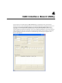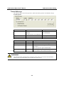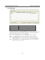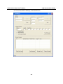
1
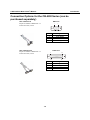
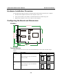
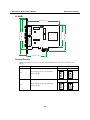
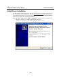
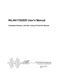
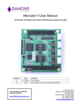
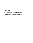
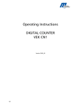
CAN Interface Board User’s Manual Second Edition, August 2009 www.moxa.com/product © 2009 Moxa Inc. All rights reserved. Reproduction without permission is prohibited. CAN Interface Board User’s Manual The software described in this manual is furnished under a license agreement and may be used only in accordance with the terms of that agreement. Copyright Notice Copyright © 2009 Moxa Inc. All rights reserved. Reproduction without permission is prohibited. Trademarks MOXA is a registered trademark of Moxa Inc. All other trademarks or registered marks in this manual belong to their respective manufacturers. Disclaimer Information in this document is subject to change without notice and does not represent a commitment on the part of Moxa. Moxa provides this document “as is,” without warranty of any kind, either expressed or implied, including, but not limited to, its particular purpose. Moxa reserves the right to make improvements and/or changes to this manual, or to the products and/or the programs described in this manual, at any time. Information provided in this manual is intended to be accurate and reliable. However, Moxa Technologies assumes no responsibility for its use, or for any infringements on the rights of third parties that may result from its use. This product might include unintentional technical or typographical errors. Changes are periodically made to the information herein to correct such errors, and these changes are incorporated into new editions of the publication. Technical Support Contact Information www.moxa.com/support Moxa Americas: Toll-free: 1-888-669-2872 Tel: +1-714-528-6777 Fax:+1-714-528-6778 Moxa Europe: Tel: +49-89-3 70 03 99-0 Fax:+49-89-3 70 03 99-99 Moxa China (Shanghai office): Toll-free: 800-820-5036 Tel: +86-21-5258-9955 Fax:+86-10-6872-3958 Moxa Asia-Pacific: Tel: +886-2-8919-1230 Fax:+886-2-8919-1231 Table of Contents Chapter 1 Introduction..............................................................................................1-1 Overview ............................................................................................................................ 1-2 Package Checklist .............................................................................................................. 1-2 Connection Options for the CB-602I Series (can be purchased separately)....................... 1-3 Product Features................................................................................................................. 1-4 Product Specifications........................................................................................................ 1-4 Chapter 2 Hardware Installation ..............................................................................2-1 Hardware Installation Procedure ........................................................................................ 2-2 Configuring the Board and Dimensions ............................................................................. 2-2 Chapter 3 Software Installation ...............................................................................3-1 Initial Driver Installation .................................................................................................... 3-2 Connecting the Hardware................................................................................................... 3-5 Windows XP, Windows 2003, and Windows Vista (32-bit and 64-bit) ................. 3-6 Installing the Driver for the CAN Controller .......................................................... 3-9 Removing the MOXA CAN Interface Board Windows Driver........................................ 3-12 Chapter 4 CAN Interface Board Utility ....................................................................4-1 Chapter 5 Pin Assignments .....................................................................................5-1 Appendix A EMI Notices ............................................................................................. A-1 EMI Notices (Class B) ...................................................................................................... A-1 GREEN Notices ................................................................................................................ A-1 1 Chapter 1 Introduction The following topics are covered in this chapter: Overview Package Checklist Connection Options for the CB-602I Series (can be purchased separately) Product Features Product Specifications CAN Interface Board User’s Manual Introduction Overview Moxa’s new CAN (Controller Area Network) interface board solutions include boards that support the Universal PCI interface, PCI Express interface, and PC/104-Plus interface. As stand-alone CAN controllers, the CP-602U-I, CP-602E-I, and CB-602I boards are cost-effective solutions. Each active CAN interface board has two independent CAN controllers with a DB9 connector. These CAN interface boards use the NXP SJA1000 and PCA82C251 transceiver, which provide bus arbitration and error detection. In addition, all models support wide temperature and have 2 KV of isolation protection built in, making the boards suitable for harsh industrial environments. The CAN interface board series includes the following models: CP-602U-I: 2-port CAN Interface Board Universal PCI board with isolation protection. CP-602U-I-T: 2-port CAN Interface Board Universal PCI board with isolation protection, -40 to 85°C operating temperature. CP-602E-I: 2-port CAN Interface Board PCI Express board with isolation protection. CP-602E-I-T: 2-port CAN Interface Board PCI Express board, with isolation protection, -40 to 85°C operating temperature0. CB-602I: 2-port CAN Interface Board PC/104-Plus module with isolation protection. CB-602I-T: 2-port CAN Interface Board PC/104-Plus module with isolation protection, -40 to 85°C operating temperature. Package Checklist The following items are included in your CAN Interface Board package: y CP-602U-I: Universal PCI Board with standard bracket, or CB-602I: PC/104-Plus Module, or CP-602E-I: PCI Express Board with standard bracket y Document & Software CD-ROM y Quick Installation Guide y 5-year Warranty Statement NOTE: Please notify your sales representative if any of the above items are missing or damaged. 1-2 CAN Interface Board User’s Manual Introduction Connection Options for the CB-602I Series (can be purchased separately) CBL-F20M9x2-50 20-pin box header to DB9 male x 2 connection cable, 50 cm DB9 male 5 1 6 Pin 2 3 5 7 CBL-F20M25x2-50 20-pin box header to DB9 male x 2 connection cable, 50 cm 9 Signal CAN_L CAN_GND Shield CAN_H DB25 male 1 14 Pin 2 3 4 7 1-3 13 25 Signal CAN_GND CAN_L CAN_H Shield CAN Interface Board User’s Manual Introduction Product Features The CAN interface board has the following features: y Supports CAN 2.0A and CAN 2.0B. y Two independent CAN controllers with DB9 connector. y CAN transfer rate up to 1 Mbps. y 2 KV optical isolation protection. y LED indicator for transmit/receive status on each port. y Optional 120 ohm terminal resistor for CAN Interface Board networks. y DLL library and examples included. y Universal PCI board supports a 3.3 V or 5 V PCI bus signal. (CP-602U-I only) y Windows drivers provided. Product Specifications Hardware CAN Controller CAN Transceiver CAN Specification Signal Support Card Interface Connectors Ports Transfer Rate Terminator Resister Max. Module Support Driver Support Library NXP SJA1000 PCA82C251 CAN 2.0 A/B CAN_H, CAN_L, GND CP-602U-I: Universal PCI CB-602I: PC/104-Plus bus module CP-602E-I: PCI Express x 1 CP-602U-I/CP-602E-I: DB9 Male CB-602I: 20-pin box header 2 1 Mbps 120 ohms (selected by jumper) 4 pcs Windows 2000, XP/2003/Vista/2008 (x86 and x64), Windows 7 C, C++, Visual Basic Physical Characteristics Dimensions Protection Optical Isolation Environment Limits Humidity (Operating) Operating Temperature Storage Temperature Regulatory Approvals CP-602U-I: 120 x 80 mm ( 4.72” x 3.15” in) CB-602I: 90 x 96 mm ( 3.54” x 3.78” in) CP-602E-I: 120 x 80 mm ( 4.72” x 3.15” in) 2 KV 5 to 95% RH Standard Models: 0 to 55° C (32 to 131° F) Wide Temp. Models: -40 to 85° C (-40 to 185° F) -40 to 85° C (-40 to 185° F) EN61000-3-3, IEC61000-4-2, IEC61000-4-3, IEC61000-4-4, 1-4 CAN Interface Board User’s Manual Introduction IEC61000-4-5, IEC61000-4-6, IEC61000-4-8, IEC61000-4-11, FCC Part 15 Class B Power Requirements Power Consumption CP-602U-I: 365 mA @ 5VDC CB-602I: 380 mA @ 5VDC CP-602E-I: 780 mA @ 5VDC Warranty 5 years Details: See www.moxa.com/warranty 1-5 2 Chapter 2 Hardware Installation In this chapter, we describe the hardware installation procedure, and provide dimensions diagrams for all three boards. The following topics are covered in this chapter: Hardware Installation Procedure Configuring the Board and Dimensions ¾ CP-602U-I ¾ CP-602E-I ¾ CB-602I CAN Interface Board User’s Manual Hardware Installation Hardware Installation Procedure Use the following simple procedure to install the Moxa CAN interface board in your computer. 1. Shut down the computer and remove the computer’s outer cover. 2. Insert your CP-602U-I, CP-602E-I, or CB-602I board into a suitable empty slot. 3. Replace the computer’s outer cover and turn on the computer. Configuring the Board and Dimensions CP-602U-I 120 mm (4.72 in) JP1 Port 2 82 mm (3.23 in) JP3 CP-602U-I 101.07 mm (3.98 in) 120.5 mm (4.74 in) Port 1 58 mm (2.28 in) 106.3 mm (4.19 in) Terminal Resistor Onboard termination resistors can be activated individually for each CAN controller using a jumper. Jumper Description Status Enabled JP1 Jumper settings for port 1 termination resistor (120 Ω) Disabled 2 2 1 1 Enabled JP3 Jumper settings for port 2 termination resistor (120 Ω) 2-2 Disabled 2 2 1 1 CAN Interface Board User’s Manual Hardware Installation CP-602E-I 100 mm (3.94 in) Port 2 85 mm (3.35 in) 72.3 mm (2.85 in) JP2 CP-602E-I 120.5 mm (4.74 in) 100.36 mm (3.95 in) Port 1 JP3 59.05 mm (2.32 in) Terminal Resistor Onboard termination resistors can be activated individually for each CAN controller using a jumper. Jumper Description Status Enabled JP2 Jumper settings for port 1 termination resistor (120 Ω) Disabled 1 1 2 2 Enable JP3 Jumper settings for port 2 termination resistor (120 Ω) 2-3 Disable 1 1 2 2 CAN Interface Board User’s Manual Hardware Installation CB-602I 90.2 mm (3.55 in) 95.9 mm (3.78 in) JP2 JP4 Rotary Switch Terminal Resistor Onboard termination resistors can be activated individually for each CAN controller using jumper. Jumper JP2 JP4 Description Status Jumper settings for port 1 termination resistor (120 Ω) Jumper settings for port 2 termination resistor (120 Ω) 2-4 Enabled Disabled 1 1 2 2 Enabled Disabled 1 1 2 2 CAN Interface Board User’s Manual Hardware Installation Rotary Switch Configuration A rotary switch on the CB-602I board makes it easy to set the appropriate signals, particularly when installing multiple PC/104-Plus modules in the same unit. The rotary switch, which looks like a clock, provides a bi-directional path with no signal propagation delay. The first module on the stack should be set to CLK0, the second to CLK1, etc., to eliminate clock skew between modules. The module stack order is shown below. Switch Position 0, 4, 8 1, 5, 9 2, 6 3, 7 Module Slot 1 2 3 4 IDSEL IDSEL0 IDSEL1 IDSEL2 IDSEL3 2-5 CLK CLK0 CLK1 CLK2 CLK3 INT# INTA# INTB# INTC# INTD# 3 Chapter 3 Software Installation Installing the CAN interface board in your computer is simple. After installing the hardware (see Chap. 2 for details) and restarting your computer the Windows operating system will load the correct drivers for the board and the CAN controller. In this chapter, basic installation procedures are explained. The screenshots shown in this chapter are for Windows XP, although the procedures are essentially the same as for Windows 2000/2003/Vista/2008 and later versions. The following topics are covered in this chapter: Initial Driver Installation Connecting the Hardware ¾ Windows XP, Windows 2003, and Windows Vista (32-bit and 64-bit) ¾ Installing the Driver for the CAN Controller Removing the MOXA CAN Interface Board Windows Driver CAN Interface Board User’s Manual Software Installation Initial Driver Installation The Documentation and Software CD contain the drivers for the CAN interface board. You may also download the drivers from Moxa’s website at http://www.moxa.com. After inserting the Documentation and Software CD in your computer, locate the CAN Interface Board/Software folder and then double-click the Setup or Install file. Step 1: Run driv_win2k_can_x.x_build_ yymmddhh.exe, located on the Documentation and Software CD-ROM. Click Next to begin installing the driver. (*Note: x.x = version, yy = year, mm = month, dd = day, hh = hour) 3-2 CAN Interface Board User’s Manual Software Installation Step 2: Click Next to install the driver in the indicated folder. 3-3 CAN Interface Board User’s Manual Software Installation Step 3: Click Install to proceed with the installation. Step 4: Moxa has thoroughly tested the driver for safe Windows operation. Click Finish to complete the driver installation. 3-4 CAN Interface Board User’s Manual Software Installation After the driver installation has been completed, the MOXA CAN interface board windows driver folder will located in the Start menu as shown below. The driver folder includes Example, Library programming guide, Library Reference, and utility. This content is provided to make it easier for users to develop their own program. Connecting the Hardware After installing the driver, power off the PC and plug the Moxa CAN interface board into any empty slot, and then power it back on. Windows will automatically detect the card and begin installing the driver. When Windows finishes installing the driver for the board, it will detect the new CAN controller, and then install the CAN controller driver. The following screenshots use CP-602U-I as an example. ATTENTION For best results, we recommend that you install the driver before plugging the board into the slot and power off the PC when plugging in the board. Please refer to the previous section on Initial Driver Installation for instructions. 3-5 CAN Interface Board User’s Manual Software Installation Windows XP, Windows 2003, and Windows Vista (32-bit and 64-bit) The following instructions are for Windows XP, Windows 2003, and Windows Vista systems. Step 1: After plugging the CAN interface board into a slot, Windows will automatically detect the new device. The Found New Hardware balloon will appear in the bottom right corner of the Windows desktop. No action is required yet. We use the CP-602U series to illustrate. Step 2: After a moment, the Found New Hardware Wizard will open. If you see the following screen, select No, not this time, and then click Next. 3-6 CAN Interface Board User’s Manual Software Installation Step 3: On the next window that appears, select Install the software automatically (Recommended), and then click Next. Step 4: Windows will spend a few moments installing the CAN interface board driver. 3-7 CAN Interface Board User’s Manual Software Installation Step 5: The next window indicates that Windows has completed the installation. Click Finish to continue with the installation procedure. Step 6: After Windows has completed installing the MOXA CAN interface board, it will automatically detect the new CAN controller. 3-8 CAN Interface Board User’s Manual Software Installation Installing the Driver for the CAN Controller After the driver for the CAN interface board have been installed, Windows will automatically detect the new CAN controller. Step 1: The Found New Hardware Wizard window will open to help you install the driver. This window will offer to connect to the Windows update site to search for a driver. Select No, not this time and then click Next to continue. Step 2: Select Install the software automatically (Recommended), and then click Next to continue. 3-9 CAN Interface Board User’s Manual Software Installation Step 3: Windows will spend a few moments installing the CAN controller driver. Step 4: After all files have been copied to the system, the Completing the Found New Hardware Wizard window will open to indicate that it has finished installing the driver. Click Finish to proceed with the rest of the installation. 3-10 CAN Interface Board User’s Manual Software Installation Step 5: Repeat Step 1 through Step 4 for each of the remaining controllers (note that there are 2 controllers for a 2-port board). Step 6: The Found New Hardware balloon will reappear to inform you that the hardware was installed successfully. Open the Windows Device Manager to check that the installation was successful. The MOXA CP-602U Series should appear under MOXA CAN Interface Board and CAN Controllers appear under MOXA CAN Controllers. 3-11 CAN Interface Board User’s Manual Software Installation Removing the MOXA CAN Interface Board Windows Driver 1. If the MOXA CAN interface board driver is no longer in use, you may click the Remove button in Windows’ Add or Remove Programs tool to remove the MOXA CAN Interface Board driver. 2. If you want to remove the driver, then click YES to continue. 3-12 CAN Interface Board User’s Manual Software Installation 3. Click OK to proceed with the un-installation procedure. 3-13 4 Chapter 4 CAN Interface Board Utility In this chapter we introduce Moxa’s MxCANTool utility to demonstrate the CAN Interface Board’s functions. After installing the Moxa CAN Interface Board Driver package, the utility will be located in Start/Programs/Moxa/MOXA CAN Interface Board Windows Driver Ver 1.0/Utility. You will see the following default panel. This panel includes three sessions: Setup, Transmit Message, and Receive Message. Users can configure the Baudrate, ACC Code, and ACC mask parameters for the CAN controllers of each board in the Setup session. When you enter the Transmit Message information and then click Send Message, the message will appear in the Receive Message box. CAN Interface Board User’s Manual CAN Interface Board Utility The MxCANTool parameters for each CAN controller can be configured during an MxCANTool Setup session. Parameter Device [Board...] Options Board 0… Board 3 Device [Controller…] Controller 0 Controller 1 10K bits/sec… Baud Rate 1000K bits/sec… User Defined BTR0/BTR1(Hex) 0x00-0xFF Open/Close ACC Code (Acceptance Code) 0-FFFFFFFF ACC Mask (Acceptance Mask) Start/Stop 0-FFFFFFFF Description Displays boards in the system. Select the CAN interface board to configure Displays controllers in the board. Select the controller to configure. Select a regular Baud Rate. If User defined is selected need to configure the BTR0/BTR1 parameters. To set a user-defined Baudrate, refer to the datasheet of NXP SJA1000 in section 6.5. Open/Close CAN controller. Set the parameter to allow the specified ID frame to be received. Refer to the cnio_set_filter_ex function from Library reference for detail. Set the parameter to mask the specified bit in frame to be received. Refer to cnio_set_filter_ex function from Library reference for detail. Set to Operation mode/Reset mode. 4-2 CAN Interface Board User’s Manual CAN Interface Board Utility Transmit Message The function sends a CAN message with or without the block operation. The default setting is Extended Frame. Parameter ID (Hex) Length Data (Hex) Options Standard Frame: 0-0x7FF Extended Frame: 0-0x1FFFFFFF 0-8 0-0xFF Parameter Standard Frame Extended Frame Remote Request Check Empty Checked Checked Self Reception Request Checked Description Set the specified ID of frame to be transmitted. Data length code of a frame. Data byte. Description 11-bit ID CAN frame 29-bit ID CAN frame(Default setting) Set the frame as remote request frame to be transmitted. Select this option to ignore the data field. Select this option to allow the frame to be received by the controller who transmits the frame. ATTENTION The Standard Frame parameter does not display on the panel. If you need to select Standard Frame, remove the checkmarks from the other three check boxes. 4-3 CAN Interface Board User’s Manual CAN Interface Board Utility Receive Message The function gets a CAN message from the received buffer with or without the block operation. Parameter Clear Data Overrun Clear Messages Message Count Receive Message Description Clear data overrun status Clear messages on the message list Displays the number of messages received The CAN message will be displayed The following screenshots illustrate the MxCANTool functions. We use the cable that follows the ISO11898 pin assignments to connect controller 0 and controller 1. The CAN message will be transmitted from controller 0 to controller 1 in a standard frame. Step 1: Open the MxCANTool utility and select controller 0; configure all parameters. Step 2: Open the MxCANTool utility and select controller 1; configure all parameters. Step 3: In the controller 0 panel, select options first and then set transmit the ID as “7FF”, Length as “8”, Data as “11, 22, 33, 44, 55, 66, 77, FF”, and then click Send Message. Step 4: In the controller 1 panel, click the Receive Message so that the CAN message will be displayed on the receive message list. 4-4 CAN Interface Board User’s Manual CAN Interface Board Utility <In Controller 0, Baudrate 500 Kbps, send standard frame > 4-5 CAN Interface Board User’s Manual CAN Interface Board Utility <In Controller 1, Baudrate 500 Kbps, receive standard frame > 4-6 5 Chapter 5 Pin Assignments The CP-602U-I and CP-602E-I come with two DB9 connectors, and the CB-602I comes with a 20-pin right-angle header connector. Even though the CB-602I comes with a 20-pin right-angle header connector, Moxa also provides a 50-cm cable, called the CBL-F20M9x2-50 or CBL-F20M25x2-50, that converts a 20-pin female connector to a DB9 or DB25 connector. The connector’s pin assignments are shown below: DB9 Male Pin 2 3 5 7 5 1 6 9 Signal CAN_L CAN_GND Shield CAN_H 20-pin right-angle header connectors Pin 3 4 5 9 Signal CAN0_L CAN0_H CAN_GND Shield Pin 13 14 15 19 Signal CAN1_L CAN1_H CAN_GND Shield DB25 Male 1 14 13 25 Pin 2 3 4 7 Signal CAN_GND CAN_L CAN_H Shield Appendix A Appendix A A EMI Notices EMI Notices (Class B) Electromagnetic Compatibility Notices FCC (U.S. Only) This device complies with part 15 of the FCC Rules. Operation is subject to the following two conditions: (1) This device may not cause harmful interference, and (2) This device must accept any interference received, including interference that may cause undesired operation. IC (Canada Only) The Class B digital apparatus meets all requirements of the Canadian Interference-Causing Equipment Regulation. Cet appareil numerique de la class [*] respecte toutes les exigences du Reglement sur le materiel brouilleur du Canada. GREEN Notices WEEE Directive - 2002/96/EC The symbol of the crossed-out wheeled bin indicates that at end-of-life of the equipment separate collection is required in the EU Member States. The black bar specifies that the appliance is put on the market after August 13, 2005. Reference: Directive 2002/96/EC.