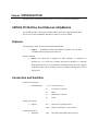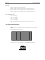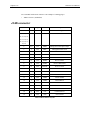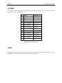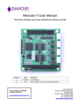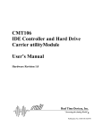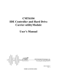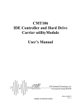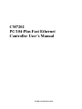
1
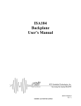
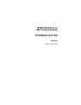
CM7202
PC/104-Plus Fast Ethernet
Controller User’s Manual
ISO9001 and AS9100 Certified
USA
Publication No. CM7202 5/3/2000
CM7202
PC/104-Plus Fast Ethernet Controller
User’s Manual
REAL TIME DEVICES USA, INC.
PO Box 906
200 Innovation Blvd.
State College, PA 16804-0906 USA
Phone: (814) 234-8087
FAX: (814) 234-5218
E-Mail
[email protected]
[email protected]
Website
www.rtdusa.com
Revision History
05/03/2000
Initial Release
Notice: We have attempted to verify all information in this manual as of the publication date.
Information in this manual may change without prior notice from Real Time Devices USA.
Published by
Real Time Devices USA, Inc.
200 Innovation Blvd.
P.O. Box 906
State College, PA 16804-0906 USA
Copyright 2000 by Real Time Devices USA, Inc.
All rights reserved
Printed in U.S.A.
PC/XT, PC/AT are registered trademarks of IBM Corporation.
PC/104 is a registered trademark of PC/104 Consortium.
The Real Time Devices Logo is a registered trademark of Real Time Devices.
utilityModule is a trademark of Real Time Devices.
Windows, Windows NT, Windows 95 are trademarks of Microsoft.
All other trademarks appearing in this document are the property of their respective owners.
Table of Contents
CHAPTER 1 - INTRODUCTION...................................................................................1-1
CM7202 PC/104-Plus Fast Ethernet utilityModule .......................................................................................... 1-1
Features................................................................................................................................................................. 1-1
Connectors and Switches..................................................................................................................................... 1-1
General Specifications ......................................................................................................................................... 1-2
CHAPTER 2 - CONFIGURING THE UTILITYMODULE...............................................2-4
Jumpers and Switches.......................................................................................................................................... 2-4
CHAPTER 3 - CONNECTORS.....................................................................................3-6
PC/104 Bus Connectors, J1 and J2..................................................................................................................... 3-6
J3 PC/104-Plus PCI connector: .......................................................................................................................... 3-8
J4 Twisted Pair Ethernet: ................................................................................................................................. 3-11
J5 MII connector: .............................................................................................................................................. 3-12
J6 LEDs............................................................................................................................................................... 3-13
JPS1: ................................................................................................................................................................... 3-13
CHAPTER 4 - INSTALLING THE UTILITYMODULE.................................................4-14
Recommended Procedure.................................................................................................................................. 4-14
Finding Pin 1 of Connectors.............................................................................................................................. 4-14
CHAPTER 5 - RETURN POLICY AND WARRANTY...................................................5-1
Return Policy........................................................................................................................................................ 5-1
Limited Warranty ................................................................................................................................................ 5-2
Chapter 1 INTRODUCTION
This manual gives information on the CM7202 PC/104-Plus Fast Ethernet utilityModule.
CM7202 PC/104-Plus Fast Ethernet utilityModule
This module provides a twisted-pair 100 Mbit ethernet connection to support the Real Time
Devices PC/104-Plus cpuModules and other PC/104-Plus processor modules.
Features
The following are major features of the CM7202 utilityModule.
•
Chipset :
Digital DEC21140 PCI Fast Ethernet Controller and ICS1890Y
10/100BaseTX integrated physical transceiver
Software Included
•
Drivers: The DEC21140 is supported by DOS, Windows 3.1, Windows 95,
Windows NT (ver.3.5 and 4.0), VxWorks and QNX. For Windows 3.1 and DOS
RTD supplies the drivers. For WindowsNT and Windows95 the drivers are supplied
by Microsoft along with the operating system. For VxWorks and QNX please contact
them directly.
Connectors and Switches
Connectors provided are:
•
CONNETTORS:
J1, J2 : PC104 connectors
J3:
PC/104-Plus Connector
J4:
RJ45
J5:
MII interface connector
J6:
LEDs
JP1:
Physical reset jumper selection.
JPS1:
Internal or External 3,3 Volt Selection.
SW1:
Phy address and module SLOT selection.
Jumpers provided are:
•
Jumpers
Switches provided are:
•
DipSwitch
Chapter Two
CM7202 User's Manual
General Specifications
•
•
•
•
Operating conditions:
Temperature: -40 - +85 degrees C
Relative humidity: 0 - 95%, non-condensing
Storage temperature: -55 to +125 degrees C
Electrical
• Compatible with PCI Specification, version 2.1.
• Compatible with PC/104 Plus version 1.1
Power Requirements:
Power requirements
Minimum
Typical
Maximum
5V Supply Voltage
4.75 V
5.00 V
5.25 V
3.3V Supply Voltage
3.3 V
3.00 V
3.6 V
Supply Current 5V
-----------
500 mA
640 mA
Supply Current 3.3V
-----------
135 mA
190 mA
Mechanical
•
•
•
Compatible with PC/104 Plus version 1.1
Dimensions: 3.8 x 3.9 x 0.6" (97 x 100 x 16 mm)
Weight (mass): 3.0 ounces (85 grams)
Environmental
•
•
•
Operating Temperature : 0° to 55° C
Storage Temperature :-40° to +85° C
Non-Condensing Relative Humidity : < 95% at 40°C
WARNING!
Like all equipment using CMOS devices, the CM7202 must be protected from static
discharge. Never touch any of the parts except at static-free workstation. Use anti-static
bag shipped with the CM7202 to handle the board
Chapter two
CM7202 User's Manual
Chapter Two
CM7202 User's Manual
Chapter 2 CONFIGURING THE UTILITYMODULE
The following sections contain information on configuring the utilityModule. Please read this
entire section before attempting to use the utilityModule!
Jumpers and Switches
Locations
The figure below shows switch and jumper locations.
10/100 MBit
Receive
Transmit
Link
Activity
Collision
Figure 1 Switch & Jumper Locations
Switch Settings
PHY Address
SW1-1
SW1-2
1
OFF
ON
0 OR NOT ATTACHED
ON
OFF
Table 1 PHY address selection
Note: In order to use MII connector for an external transceiver the user must set the PHY address
to 0 in order to have the physical interface isolated and set the JUMPER JP1 to the position 2-3.
Chapter two
CM7202 User's Manual
SLOT Selected
SW1-3
SW1-4
1
ON
ON
2
OFF
ON
3
ON
OFF
4
OFF
OFF
Table 2 Module slot address selection
Chapter Two
CM7202 User's Manual
Chapter 3 CONNECTORS
PC/104 Bus Connectors, J1 and J2
Connectors J1 and J2 provide PC/104 bus connections. J1 carries XT bus signals, and J2 carries
additional signals for the AT bus. The signals on J1 and J2 conform to the IEEE P966 standard for
the PC/104 bus.
Chapter two
CM7202 User's Manual
The following tables list the connector pinouts:
PC/104 XT Bus Connector, J1
Pin
Row A
Row B
1
IOCHCHK*
0V
2
SD7
RESETDRV
3
SD6
+5V
4
SD5
IRQ9
5
SD4
-5V
6
SD3
DRQ2
7
SD2
-12V
8
SD1
ENDXFR*
9
SD0
+12V
10
IOCHRDY
(KEYING PIN)
11
AEN
SMEMW*
12
SA19
SMEMR*
13
SA18
IOW*
14
SA17
IOR*
15
SA16
DACK3
16
SA15
DRQ3
17
SA14
DACK1*
18
SA13
DRQ1
19
SA12
REFRESH
20
SA11
SYSCLK
21
SA10
IRQ7
22
SA9
IRQ6
23
SA8
IRQ5
24
SA7
IRQ4
25
SA6
IRQ3
26
SA5
DACK2*
27
SA4
TC
28
SA3
BALE
29
SA2
+5V
30
SA1
OSC
31
SA0
0V
32
0V
0V
Table 5 PC/104 XT Bus Connector
Chapter Two
CM7202 User's Manual
PC/104 AT Bus Connector, J2
Pin
Row C
Row D
0
0V
0V
1
SBHE*
MEMCS16*
2
LA23
IOCS16*
3
LA22
IRQ10
4
LA21
IRQ11
5
LA20
IRQ12
6
LA19
IRQ15
7
LA18
IRQ14
8
LA17
DACK0*
9
MEMR*
DRQ0
10
MEMW*
DACK5*
11
SD8
DRQ5
12
SD9
DACK6*
13
SD10
DRQ6
14
SD11
DRQ6
15
SD12
DRQ7
16
SD13
+5V
17
SD14
MASTER*
18
SD15
0V
19
(KEYING PIN)
0V
Table 6 PC/104 AT Bus Connector
Note:
Two locations on the bus have mechanical keying pins to help prevent misconnection
of the PC/104 bus. These keying pins are a part of the PC/104 standard, and we
strongly recommend you leave them in place.
If you have other modules without keying pins, we suggest you modify them to
include keying.
J3 PC/104-Plus PCI connector:
Connector J3 carries the signals of the PC/104-Plus PCI bus. These signals match definitions of
the PCI Local Bus specification Revision 2.1. The following tables list the pinouts of the PC/104Plus bus connector.
PC/104-Plus Bus Signal Assignments
Chapter two
Pin
1
2
3
4
5
6
7
8
9
10
11
12
13
14
15
16
17
18
19
20
21
22
23
24
25
26
27
28
29
30
CM7202 User's Manual
A
GND/5.0V KEY1
VI/O
AD05
C/BE0*
GND
AD11
AD14
+3.3V
SERR*
GND
STOP*
+3.3V
FRAME*
GND
AD18
AD21
+3.3V
IDSEL0
AD24
GND
AD29
+5V
REQ0*
GND
GNT1*
+5V
CLK2
GND
+12V
-12V
B
Reserved
AD02
GND
AD07
AD09
VI/O
AD13
C/BE1*
GND
PERR*
+3.3V
TRDY*
GND
AD16
+3.3V
AD20
AD23
GND
C/BE3*
AD26
+5V
AD30
GND
REQ2*
VI/O
CLK0
+5V
INTD*
INTA*
Reserved
C
+5V
AD01
AD04
GND
AD08
AD10
GND
AD15
SB0*
+3.3V
LOCK*
GND
IRDY*
+3.3V
AD17
GND
AD22
IDSEL1
VI/O
AD25
AD28
GND
REQ1*
+5V
GNT2*
GND
CLK3
+5V
INTB*
Reserved
D
AD00
+5V
AD03
AD06
GND
M66EN
AD12
+3.3V
PAR
SDONE
GND
DEVSEL*
+3.3V
C/BE2*
GND
AD19
+3.3V
IDSEL2
IDSEL3
GND
AD27
AD31
VI/O
GNT0*
GND
CLK1
GND
RST*
INTC*
GND/3.3V KEY1
Notes:
1. The KEY pins are to guarantee proper module installation. Pin-A1 will be removed and the
female side plugged for 5.0V I/O signals and Pin-D30 will be modified in the same manner for
3.3V I/O. It is recommended that both KEY pins (A1 and D30) be electrically connected to GND
for shielding.
Chapter Two
CM7202 User's Manual
PC/104-Plus PCI Bus Signals
The following table contains brief descriptions of the PC/104-Plus PCI bus signals.
Address and Data
AD[31:00] -- Address and Data are multiplexed. A bus transaction consists of an address cycle followed by one or more data cycles.
C/BE[3:0]* -- Bus Command/Byte Enables are multiplexed. During the address cycle, the command is defined. During the Data cycle, they define the byte enables.
PAR -- Parity is even on AD[31:00] and C/BE[3:0]* and is required.
Interface Control Pins
FRAME* -- Frame is driven by the current master to indicate the start of a transaction and will remain active until the final data cycle.
TRDY* -- Target Ready indicates the selected devices ability to complete the current data cycle of
the transaction. Both IRDY* and TRDY* must be asserted to terminate a data cycle.
IRDY* -- Initiator Ready indicates the master's ability to complete the current data cycle of the
transaction.
STOP* -- Stop indicates the current selected device is requesting the master to stop the current
transaction.
DEVSEL* -- Device Select is driven by the target device when its address is decoded.
IDSEL -- Initialization Device Select is used as a chip-select during configuration.
LOCK* -- Lock indicates an operation that may require multiple transactions to complete.
Error Reporting
PERR* -- Parity Error is for reporting data parity errors.
SERR* -- System Error is for reporting address parity errors.
Arbitration (Bus Masters Only)
REQ* -- Request indicates to the arbitrator that this device desires use of the bus.
GNT* -- Grant indicates to the requesting device that access has been granted.
System
CLK -- Clock provides timing for all transactions on the PCI bus.
RST* -- Reset is used to bring PCI-specific registers to a known state.
Chapter two
CM7202 User's Manual
Interrupts
INTA* -- Interrupt A is used to request Interrupts.
INTB* -- Interrupt B is used to request Interrupts only for multi-function devices.
INTC* -- Interrupt C is used to request Interrupts only for multi-function devices.
INTD* -- Interrupt D is used to request Interrupts only for multi-function devices.
Power Supplies and VIO
+5V -- +5 volt supply
+12V -- +12 volt supply
-12V -- -12 volt supply
+3.3V -- +3.3 volt supply
VIO -- This signal typically is the I/O power to the bus drivers on a PCI bus card.
J4 Twisted Pair Ethernet:
Connector J4 is for UTP (Unshielded Twisted Pair) wiring normally used for 10/100Base-T
Ethernet.
The following table gives the pinout of J4.
Pin
1
2
3
4
5
6
7
8
Signal
TX+
TXRX+
N.C.
N.C.
RXN.C.
N.C.
Function
Transmit +
Transmit Receive +
Reserved
Not connected
Receive Not connected
Not connected
in/out
out
out
in
in
The figure below shows the pin numbering of J4 when looking into the connector:
1 2 3 4 5 6 7 8
RJ-45 Jack Connector
Chapter Two
CM7202 User's Manual
J4 is a standard female RJ-45 connector. One example of a mating plug is:
•
AMP 5-554739-3 (unshielded)
J5 MII connector:
Pin Number
I/O
Type
Name
Description
1, 20, 21, 40
Power
+5V
5 Volt supply
22, 23, 24, 25,
Power
GND
Ground
26, 27, 28, 29,
30, 31, 32, 33,
34, 35, 36, 37,
38, 39
2
I/O
TTL
MDIO
Management Data Input Output
3
I
TTL
MDC
Management Data Clock
4
O
TTL
RXD3
Receive Data 3
5
O
TTL
RXD2
Receive Data 2
6
O
TTL
RXD1
Receive Data 1
7
O
TTL
RXD0
Receive Data 0
8
O
TTL
RXDV
Receive Data Valid
9
O
TTL
RXCLK
Receive Clock
10
O
TTL
RXER
Receive Error
11
------
Pulldown
--------
----------------
12
O
TTL
TXCLK
Trasmit Clock
13
I
TTL
TXEN
Trasmit Enable
14
I
TTL
TXD0
Trasmit Data 0
15
I
TTL
TXD1
Trasmit Data 1
16
I
TTL
TXD2
Trasmit Data 2
17
I
TTL
TXD3
Trasmit Data 3
18
O
TTL
COL
Collision Detect
19
O
TTL
CRS
Carrier Sense
Table 3 MII Connector Layout
Chapter two
CM7202 User's Manual
J6 LEDs
This connector is made for direct connection to the LEDs on the Board. The connector is a 1x12, 2.54 mm pin strip.
The connector’s layout is the following:
PIN
NAME
DESCRIPTION
1
LED 1 ANODE
Collision LED
2
LED 1 CATHODE
Collision LED
3
LED 2 ANODE
Activity LED
4
LED 2 CATHODE
Activity LED
5
LED 3 ANODE
Link LED
6
LED 3 CATHODE
Link LED
7
LED 4 ANODE
Trasmit LED
8
LED 4 CATHODE
Trasmit LED
9
LED 5 ANODE
Receive LED
10
LED 5 CATHODE
Receive LED
11
LED 6 ANODE
10/100 Selection
12
LED 6 CATHODE
10/100 Selection
Table 4 J6 LED connector layout
JPS1:
The CM7202 can use the 3,3 Volt supply by the PC/104-Plus connector or from the internal linear regulator. The
default setting is from the Internal Linear regulator. It is set to the position 1-2.
Chapter Two
CM7202 User's Manual
Chapter 4 INSTALLING THE UTILITYMODULE
Since the utilityModule uses a PC/104 stackthrough bus, the only hardware installation you will do
is placing the module to the PC/104 stack. To do this, you will connect the PC/104 bus connector
with the matching connector of another module.
Recommended Procedure
We recommend you follow the procedure below to ensure that stacking of the modules does not
damage connectors or electronics.
•
Turn off power to the PC/104 system or stack.
•
Select and install standoffs to properly position the utilityModule on the PC/104 stack.
•
Touch a grounded metal part of the stack to discharge any buildup of static electricity.
•
Remove the utilityModule from its anti-static bag.
•
Check that keying pins in the PC/104 bus connector are properly positioned.
•
Check the stacking order: make sure an XT bus card will not be placed between two AT bus
cards, or it will interrupt the AT bus signals.
•
Hold the utilityModule by its edges and orient it so the bus connector pins line up with the
matching connector on the stack.
•
Gently and evenly press the utilityModule onto the PC/104 stack.
CAUTION: Do not force the module onto the stack! Wiggling the module or applying too much
force may damage it. If the module does not readily press into place, remove it, check
for bent pins or out-of-place keying pins, and try again.
Connecting the utilityModule
The following sections describe connectors of the utilityModule.
Finding Pin 1 of Connectors
A white area silk-screened on the PC board indicates pin 1 of connectors. A square solder pad
visible on the bottom of the PC board also indicates it.
Chapter 5 RETURN
POLICY AND WARRANTY
Return Policy
If the utilityModule requires repair, you may return it to us by following the procedure listed
below:
Caution:
Failure to follow this return procedure will almost always delay repair! Please help us
expedite your repair by following this procedure.
1) Read the Limited Warranty that follows.
2) Contact the factory and request a Returned Merchandise Authorization (RMA) number.
3) On a sheet of paper, write the name, phone number, and fax number of a technically competent
person who can answer questions about the problem.
4) On the paper, write a detailed description of the problem with the product. Answer the following
questions:
• Did the product ever work in your application?
• What other devices were connected to the product?
• How was power supplied to the product?
• What features did and did not work?
• What was being done when the product failed?
• What were environmental conditions when the product failed?
5) Indicate the method we should use to ship the product back to you.
•
•
•
We will return warranty repairs by UPS Ground at our expense.
Warranty repairs may be returned by a faster service at your expense.
Non-warranty repairs will be returned by UPS Ground or the method you select, and
will be billed to you.
6) Clearly specify the address to which we should return the product when repaired.
7) Enclose the paper with the product being returned.
8) Carefully package the product to be returned using anti-static packaging! We will not be
responsible for products damaged in transit for repair.
7) Write the RMA number on the outside of the package.
8) Ship the package to:
Real Time Devices
200 Innovation Blvd.
State College PA 16803
USA
Chapter Four
User's Manual
Limited Warranty
Real Time Devices, Inc. warrants the hardware and software products it manufactures and
produces to be free from defects in materials and workmanship for one year following the date of
shipment from REAL TIME DEVICES. This warranty is limited to the original purchaser of
product and is not transferable.
During the one year warranty period, REAL TIME DEVICES will repair or replace, at its option,
any defective products or parts at no additional charge, provided that the product is returned,
shipping prepaid, to REAL TIME DEVICES. All replaced parts and products become the property
of REAL TIME DEVICES. Before returning any product for repair, customers are required to
contact the factory for an RMA number.
THIS LIMITED WARRANTY DOES NOT EXTEND TO ANY PRODUCTS WHICH HAVE
BEEN DAMAGED AS A RESULT OF ACCIDENT, MISUSE, ABUSE (such as: use of incorrect
input voltages, improper or insufficient ventilation, failure to follow the operating instructions that
are provided by REAL TIME DEVICES, "acts of God" or other contingencies beyond the control
of REAL TIME DEVICES), OR AS A RESULT OF SERVICE OR MODIFICATION BY
ANYONE OTHER THAN REAL TIME DEVICES. EXCEPT AS EXPRESSLY SET FORTH
ABOVE, NO OTHER WARRANTIES ARE EXPRESSED OR IMPLIED, INCLUDING, BUT
NOT LIMITED TO, ANY IMPLIED WARRANTIES OF MERCHANTABILITY AND
FITNESS FOR A PARTICULAR PURPOSE, AND REAL TIME DEVICES EXPRESSLY
DISCLAIMS ALL WARRANTIES NOT STATED HEREIN. ALL IMPLIED WARRANTIES,
INCLUDING IMPLIED WARRANTIES FOR MECHANTABILITY AND FITNESS FOR A
PARTICULAR PURPOSE, ARE LIMITED TO THE DURATION OF THIS WARRANTY. IN
THE EVENT THE PRODUCT IS NOT FREE FROM DEFECTS AS WARRANTED ABOVE,
THE PURCHASER'S SOLE REMEDY SHALL BE REPAIR OR REPLACEMENT AS
PROVIDED ABOVE. UNDER NO CIRCUMSTANCES WILL REAL TIME DEVICES BE
LIABLE TO THE PURCHASER OR ANY USER FOR ANY DAMAGES, INCLUDING ANY
INCIDENTAL OR CONSEQUENTIAL DAMAGES, EXPENSES, LOST PROFITS, LOST
SAVINGS, OR OTHER DAMAGES ARISING OUT OF THE USE OR INABILITY TO USE
THE PRODUCT.
SOME STATES DO NOT ALLOW THE EXCLUSION OR LIMITATION OF INCIDENTAL
OR CONSEQUENTIAL DAMAGES FOR CONSUMER PRODUCTS, AND SOME STATES
DO NOT ALLOW LIMITATIONS ON HOW LONG AN IMPLIED WARRANTY LASTS, SO
THE ABOVE LIMITATIONS OR EXCLUSIONS MAY NOT APPLY TO YOU.
THIS WARRANTY GIVES YOU SPECIFIC LEGAL RIGHTS, AND YOU MAY ALSO HAVE
OTHER RIGHTS THAT VARY FROM STATE TO STATE.