1
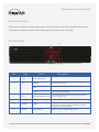
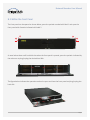
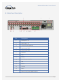
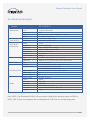
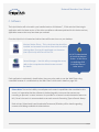
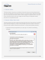
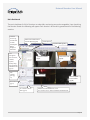
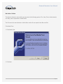
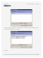
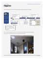
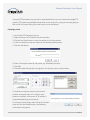
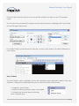
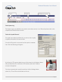
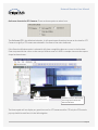
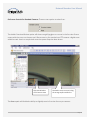
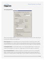
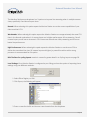
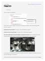
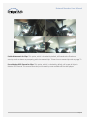
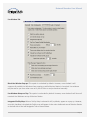
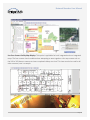
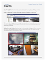
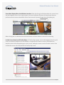
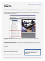
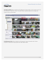
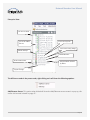
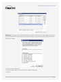
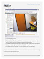
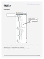
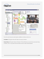
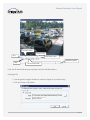
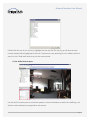
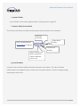
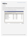
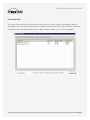
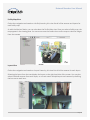
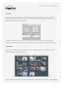
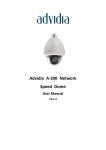
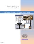
Unparalleled Hardware Flexibility
Network Recorder
User Manual
www.bridgevms.com
Network Recorder User Manual
Unparalleled Hardware Flexibility
Table of Contents
A. Overview ................................................................................................................................
A.1 Device Details ................................................................................................................
A.2 Recommendations ........................................................................................................
B. Device Interface
................................................................................................................
B.1 Front Panel
................................................................................................................
B.2 Within the Front Panel
................................................................................................
B.3 Back Panel Description ................................................................................................
B.4 Additional Description
................................................................................................
C. Software ................................................................................................................................
C.1 Monitor Station ................................................................................................................
C.2 Monitor Station Client Install ........................................................................................
Add Servers Manually ........................................................................................................
Add Servers Automatically
................................................................................................
D. Login ........................................................................................................................................
Main Dashboard
................................................................................................................
Main Menu Toolbar ................................................................................................................
a. Left Navigation Tree ........................................................................................................
b. PTZ Controls pane ........................................................................................................
c. Search Pane
................................................................................................................
d. Live Audio Controls pane ................................................................................................
e. Layouts Toolbar
........................................................................................................
f. Camera’s Quick Access toolbar ........................................................................................
g. Server Statistics
........................................................................................................
E. Media Player
........................................................................................................................
a. Left Navigation Tree ........................................................................................................
b. Toolbar ........................................................................................................................
F. Synchronized Player ................................................................................................................
a. Synchronized Player Clip Option
................................................................................
G. Web Client ................................................................................................................................
a. Configuring IIS ................................................................................................................
b. Accessing the Web Client
........................................................................................
c. Using the Web Client
................................................................................................
3
3
3
4
4
5
6
7
8
9
9
13
14
16
19
20
57
73
73
74
75
75
75
82
87
82
90
93
95
95
96
97
Page 2
Network Recorder User Manual
Unparalleled Hardware Flexibility
A. Overview
The BH-16/16 model is a hybrid device that can be used for both Analog and IP Cameras at once allowing
the organization to utilize up to 16 Analog cameras as well as 16 or more IP cameras depending on the
bitrate, resolution and other factors.
A.1 Device Details
√ Support 16-ch analog input with 4CIF(D1)/CIF real-time encoding
√ Support up to 16-ch 4CIF (main stream) +16-ch CIF (sub stream) encoding under dual stream
encoding mode.
√ Support 16-ch alarm in and 4-ch alarm out
√ Atom N270 1.6GHZ CPU with low power consumption
√ Open IA structure, various PC application software can be applied to the product
√ Two 1000M Ethernet interfaces, support multiple IPC connection
√ Support multiple analog video & audio input
√ Support H.264 hardware compression
√ Programmable front panel button & LED configuration
√ Compact and flexible structure design
A.2 Recommendations
Before connecting and operating your device, consider the following:
√ Ensure unit is installed in a well-ventilated, dust-free environment
√ Unit is designed for indoor use only
√ Keep all liquids away from the Device
√ Dropping the unit due to a faulty install location may damage the internal sensitive electronics
within the unit
√ Use a Universal Power Supply if possible
√ Power down the unit before connecting and disconnecting accessories and peripherals
√ Use a reliable HDD to ensure best performance and storage
√ CPU Usage will vary depending on the models of IP cameras used and their specific
configurations
Page 3
2
Network Recorder User Manual
Unparalleled Hardware Flexibility
B. Device Interface
The device was created for organizations with a need for a medium size camera implementation and a
small area for storage of the device itself allowing up to 8 drives and lots of storage.
B.1 Front Panel
1
4
No.
Type
Name
2
5
3
6
Description
1
Lock
Front Panel Lock
2
LED
POWER
Power LED will be red for standby status and green if
the device is running
HDD
HDD LED blinks on hard disk write/read status
Tx/Rx
Tx/Rx blinks with red or green color when there is
network data transmission
LED status programmable via SDK, the LED can be set
as red or green color
3
LED
Channel indicator 1-16
4
Interface
USB 2.0
5
Button
Power
Press the Power button for over 1.3 seconds to shut
down the unit, yet if you press more than 4 seconds,
it will execute force shutdown.
6
Button
User-Defined
Button response programmable via SDK
Page 4
Network Recorder User Manual
Unparalleled Hardware Flexibility
B.2 Within the Front Panel
The front panel can be opened as shown below; press the position marked with label 1 and open the
front panel with direction indicated with label 2.
As seen below there are 8 hard disk slots when the front panel is opened; press the position indicated by
the red arrow to plug/unplug the desired hard disk.
The figure below indicates the operation method to open and close the front panel and plug/unplug the
hard disk.
Page 5
Network Recorder User Manual
Unparalleled Hardware Flexibility
B.3 Back Panel Description
1
4
5 6
7 8
No.
2
9
10 11 12 13
3
14
Description
1
Video input 1-16
2
Audio input 1-16
3
Video Loop Out (Optional)
4
Audio output (DSP)
5
Video output (DSP)
6
Reserved
7
VGA
8
RS-232
9
RJ45 Ethernet interface
10
USB
11
Line In
12
Line Out
13
Mic In
14
Alarm I/O (16/4) and RS485 interface
Page 6
Network Recorder User Manual
Unparalleled Hardware Flexibility
B.4 Additional Description
Model
Motherboard
Video/Audio In
Video/Audio
Compression
HDD
Other Drivers
External Interface
Others
DS-5216HFI-A
CPU
Memory
VGA
Audio
Analog Video Input
Audio Input
Video
Playback
Frame Rate
Bit Rate
Stream Type
Audio
Audio Bit Rate
Type
Maximum
Type
Netwrok
Serial Interface
USB Interface
Alarm Input
Alarm Output
Power Supply
Power
Working
Working
Chassis
Dimension
Weight (Not include HD)
Intel Atom N270 2GB
2GB
1, support up to 1900*1200@60HZ resolution
Line In/Line Out/Mic In
16-ch BNC (1.0Vp-p, 75Ω)
16-ch BNC (2.0Vp-p, 1kΩ)
H.264
4CIF/2CIF/CIF/QCIF
PAL: 1~25 fps, NTSC: 1~30fps
32Kbps-4Mbps user adjustable
Video / Video & Audio
G. 711A-law
64kbps
10 SATA Interface (Refer to Note below)
Support up to 2TB hard disk for each HDD interface
1 CF card interface
2 RJ45 10M/100M/1000M adaptive Ethernet port
1 standard RS-485 serial interface
1 standard RS-232 serial interface
2 in front panel and 2 in rear panel, USB 2.0
16
4
AC220V, 47--63 HZ
≤50W
0°C--50°C
10%--90%
19” Standard 2U Chassis
441mm(W) ×470mm(D) ×90mm(H)
≤8Kg
Note: SATA1-2 can be detected by BIOS. We recommend installing the operating system on SATA1 or
SATA2; SATA 3-10 can be recognized after installing Marvell 6145 driver on the operating system.
Page 7
Network Recorder User Manual
Unparalleled Hardware Flexibility
C. Software
The hybrid device will arrive with a pre-installed version of Windows 7, 32 bit and the Video Insight
application with the latest version of the video surveillance software optimized for this device and any
applicable cameras that may have been pre-ordered.
Once the Hybrid unit is booted and online there will be two icons on your desktop:
Monitor Station Client – This is the client that should be
installed and accessed from other client machines when
viewing video. Running this application on the server
(the Hybrid unit) will max out the CPU.
................
................
................
Server Manager – Use this utility to manage the server,
refer to the comprehensive Administrator manual
for details.
It is NOT recommended
to launch the Monitor
Station or Web Client
on the Bridge DVR ,
install the Client on
other servers.
Each application is explained in detail below. Users may also prefer to use the Web Client using
a standard browser or a mobile device; the Web Client is discussed in detail on page 100.
Please Note: Due to the inability to anticipate each camera’s capabilities that are added to this
server it is imperative that the software is checked regularly to ensure that cameras are
recording as planned. In some instances it is possible for a camera’s motion detection feature to
fail; if that’s the case it is recommended to set each camera’s Recording Type to Record Always.
Refer to http://downloadvi.com/downloads/Documents/50admin.pdf for details regarding
cameras and settings available to Administrators.
Page 8
Network Recorder User Manual
Unparalleled Hardware Flexibility
C.1 Monitor Station
The Monitor Station is the primary user interface in the product suite and can be considered the hub
from which all configurations and monitoring is done from. Any Monitor Station configuration will affect
the current client where that Monitor Station is installed, changes will not affect the server or any other
Clients, unless Administrator Level access changes are made in Setup and Configuration notated
discussed in our comprehensive manual.
C.2 Monitor Station Client Install
The Monitor Station client will be installed automatically with either the IP Enterprise Server Install OR IP
Server install with Existing SQL so a client is easily accessible from the server as well. In some cases a
Client only install is needed for Video Monitor personnel; if so, follow these installation procedures:
1. Double click the Setup.exe applicable to your system type: 32 or 64 bit OS, the following
will appear:
Page 9
Network Recorder User Manual
Unparalleled Hardware Flexibility
2. Click the Agree button to accept the terms and continue the installation; otherwise choose Cancel to
terminate the installation. The following will appear:
3. The second option: Monitor Station install should be selected.
4. Click Next, following will appear:
Page 10
Network Recorder User Manual
Unparalleled Hardware Flexibility
1. Enter the destination folder if different than the default by selecting Browse; most customers using a
server with multiple drives may choose to install Programs in the D:\ location rather than
the OS drive.
2. Click Install, following will appear:
3. Click Next
4. Click Finish
5. Click Yes to the Reboot prompt
6. Monitor Station is now installed and ready to be initialized and configured.
7. Double click the Monitor Station icon on your desktop
8. Click OK to bypass the Login prompt
9. At minimum one server should be entered before the Client can be used, the following Server Setup
pop-up will appear:
Page 11
Network Recorder User Manual
Unparalleled Hardware Flexibility
There are several ways to enter servers, you may enter one server at a time, or import a list of servers
used throughout your organization; we’ll cover both options below.
Please Note: The licensing structure of this device limits the number of servers that can be
added. Adding more than 3 (three) servers will display the following error: “Error: Server license
is exceeded.”
Page 12
Network Recorder User Manual
Unparalleled Hardware Flexibility
Add Servers Manually
1. In the Server Setup pop-up above click the Add New button
2. Enter the IP Address or name of the server to connect to; change the port if different than default.
3. Click the Test button to initiate a connection, the attempt to connect may result in one of three
possible states:
Login Error: The server is found but security is on and the server attempted to authenticate with
the credentials we used when login in to MS initially (Administrator/blank). The server can still be
added and once added log out and back into Monitor Station with the right credentials.
No Server Found: Either the IP Address, Name, Port number or a combination is incorrect.
Change the values and attempt to Test again.
Server Found: The server is found, connection was made successfully using current credentials
(Administrator/blank) since security is off. The Server’s name will appear in the Status field.
4. Click Add
5. Repeat steps 1-5 for any additional servers
6. Click Apply and OK
Page 13
Network Recorder User Manual
Unparalleled Hardware Flexibility
Add Servers Automatically
When the Video Insight software is used in a large organization or School Districts it is possible to have
upwards of 20 or more Video Surveillance servers across multiple locations. To easily add a long list of
servers at once use the import feature as shown below.
An already exported list of servers is needed; the file format should be an ‘lsl’ file. For instructions on
how to create this file refer to the Login section on page on 20.
1. In the Server Setup pop-up click the Import List button
2. Browse to the location of the saved ‘lsl’ file as shown below:
3. Click OK
4. If the file is unreadable, or not found an error will appear. Otherwise the full list of servers will now
appear in the Known Video Servers grid. A prompt asking to restart Monitor Station will also appear:
Page 14
Network Recorder User Manual
Unparalleled Hardware Flexibility
5. Click OK to acknowledge
6. Click Apply and OK
7. Restart Monitor Station by clicking the Lock icon on the upper left of the main dashboard as
shown here:
8. At the Login prompt enter the credentials to login to the desired server(s) or Click OK to bypass the
Login screen without any credentials.
Page 15
Network Recorder User Manual
Unparalleled Hardware Flexibility
D. Login
Upon installation the software is installed with security off enabling login free access to the Monitor
Station and Web Clients. Security can be easily turned on by accessing the Server properties as
discussed in the Administrator manual.
Depending on your specific company and security specifications you may choose any one or a combi
nation of login options currently available to you; each is explained in detail below.
1. Launch Monitor Station by clicking the Desktop icon
Local User Mode: The first option when selected can be used on its own or in combination with the
Windows Login checkbox (discussed later). When used on its own it behaves differently depending on
several settings.
Security On: when Security is turned on for the server the credentials entered will be checked for
validity against the User Manager in Monitor Station.
Security Off: when Security is not enabled for a server all logins will be accepted, any combination of
With Windows Login Check enabled: In this case it assumes that an Active Directory (AD) or an LDAP
configuration has been implemented and ALL users will be authenticated against Active Directory
and/or the User Manager in Monitor Station (since all AD/LDAP users are imported to the User Man
ager) as long as Security for the server is turned on.
Page 16
Network Recorder User Manual
Unparalleled Hardware Flexibility
To login using Active Directory from the Login screen:
1. Launch Monitor Station by clicking the desktop icon
2. Click the Options>> button
3. Check the Windows Login checkbox
4. Select the Domain from the dropdown if not already defaulted
5. Enter the Username and Password
6. Click OK
Page 17
Network Recorder User Manual
Unparalleled Hardware Flexibility
Network User Mode: This option is very useful in large environments where there are multiple Clients
and servers. Instead of adding every server to each client and then having to manage multiple lists when
adding or removing servers from Setup and Config, the following may be utilized;
In one Monitor Station add all of the servers:
1. Navigate to Setup and Config
2. Add all of the servers, one by one, to the Known Video Servers list.
3. Click Export List, save it on a Shared location
4. An “.lsl” file is created with all servers
Point all other users to Browse to that same file which will give them the latest server information each
time they log in without having to manage hundreds of clients , the administrator will just need to
manage that one .lsl file by adding or removing any servers at any time without affecting daily business
functions.
This option may also be used with Active Directory or LDAP configuration using the Windows Login Mode
checkbox.
You may also bypass the Login pop-up all together with or without Security being on by setting the Auto
Login option as follows:
1. Launch Monitor Station
2. Navigate to Tools>Options
3. Click the Startup Tab
4. Check Enable Auto Login
a. With security off you may just check it; credentials are not needed
b. With security on you must provide valid credentials.
Page 18
Network Recorder User Manual
Unparalleled Hardware Flexibility
Main Dashboard
The main dashboard is full of functions to make daily monitoring easy and manageable. Upon launching
the Monitor Station the following will appear. Each section is discussed in greater detail in the following
sections.
Click the
Lock to log
out and back
in when
restarting the
MS for
changes to
take affect
Main menu toolbar with a
slew of options (pg 22)
View options)
Layout toolbar (pg 28)
Left
Navigation
tree of servers,
cameras,
layouts,
facility maps,
Action buttons
and HM access
(pg 59)
Quick launch Media
Player
PTZ
Controls
pane (pg
31)
Cameras live view
(pg 80)
Camera’s name
Camera’s quick
Access toolbar
(pg 80)
Search Pane
(pg 77)
Live Audio Controls
Pane (pg 79)
Number of connected Servers; Click
View>Status>Server Status to hide this information bar
Page 19
Network Recorder User Manual
Unparalleled Hardware Flexibility
Main Menu Toolbar
The Monitor Station’s main toolbar encompasses the following options: File, View, Tools, Administration
and Help; each is explained in detail below.
The File menu has two selections: Media fixer used to fix corrupted video files and Exit.
File>Media Fixer
1. Click Media Fixer
2. Click Next
Page 20
Network Recorder User Manual
Unparalleled Hardware Flexibility
3. Choose to add single multiple files or complete folders of videos to be fixed, once added a full list of
each video’s path will appear as shown below:
4. Click Next
Page 21
Network Recorder User Manual
Unparalleled Hardware Flexibility
5. Leave the first option selected and click Fix Files to begin the process. If choosing the second option:
Specify File Information it is recommended to provide the correct file header information as fixing it
with incorrect information may render the file unusable.
6. The pop-up will appear on the screen until all files are fixed, once complete it will include the path of
the fixed file as shown below:
Page 22
Network Recorder User Manual
Unparalleled Hardware Flexibility
7. The word ‘fixed’ will be appended to the file name, the original file will still be available.
8. Click Finish to exit this utility
File>Exit
Once clicked, Monitor Station will prompt for a confirmation to exit the application. This function is
exactly as if pressing the Lock Icon.
It is possible to exit the application without having to confirm by unchecking the Exit confirmation
checkbox in Tools>Options>General tab.
Page 23
Network Recorder User Manual
Unparalleled Hardware Flexibility
The View menu has six selections: Archive Tree, Full Screen, Layout, Mini Toolbars, Status and Toolbars.
View>Archive Tree
The Archive Tree option is elected by default, when unchecking it the left tree navigation will be
hidden. This option is useful when wanting to view more of the monitor’s real estate for the Live
view streaming.
Default view with Archive Tree selected:
Page 24
Network Recorder User Manual
Unparalleled Hardware Flexibility
View with Archive Tree deselected:
View>Full Screen
This option, also available by pressing the F11 key on your keyboard, will expand the main dashboard
view to span the full size of your monitor.
View>Layout
The view Layout option will show a full list of the
predefined layouts and it will change the number
of cameras visible in the main dashboard view.
Use the shortcut
keys on your
keyboard to
change the layout
Page 25
Network Recorder User Manual
Unparalleled Hardware Flexibility
View>Mini Toolbars
The Mini Toolbars option includes Cycle Layouts and Ptz Controls standalone pop-ups that can be repositioned anywhere on your dashboard for easy access to those functions.
Cycle Layouts
Video monitors and Police Officers may be assigned to a particular area and as such may need to
review only certain locations which are usually grouped by server. For example, one Monitor
Station may have multiple Servers, one per campus so when doing your usual virtual walkthrough
of the campus you may need to review only one server and cycling Layouts is one way to
accomplish that quickly and easily.
There are two ways a user may cycle Layouts: manually or automatically. Manual Layouts cycling is
done by pressing any of the predefined Layout buttons shown below:
To configure the one server cycling for manual selection:
1. Access Tools>Options
2. On the General tab check the “Use tree navigation server selection for default layout buttons”
checkbox as shown on the next page.
Page 26
Network Recorder User Manual
Unparalleled Hardware Flexibility
3. Log out and back into the Monitor Station to refresh the settings.
4. Select a server (it will appear highlighted) from the left navigation
5. Click any of the Layout buttons and notice only that server’s cameras will be selected for
the layout view.
To configure the one server cycling for automatic selection:
1. Access Tools>Options
2. On the Tools Configuration tab check the “Layouts cycle through current server” checkbox as
shown on the next page. Checked is the default value for this checkbox.
Page 27
Network Recorder User Manual
Unparalleled Hardware Flexibility
3. Log out and back into the Monitor Station to refresh the settings.
4. Click View>Mini Toolbars>Cycle Layouts
5. Click the Layout scheme of your choice and press the Play button
Page 28
Network Recorder User Manual
Unparalleled Hardware Flexibility
PTZ Controls
The ability to control PTZ operations for a PTZ capable camera is accessible from multiple locations in the
application while offering a slight variation in capability from each location.
The View>Mini Toolbars>PTZ Controls pop-up is as follows:
Camera name
Will select the next PTZ
capable camera on the
server to mange
Use arrows
to pan left
right, up or
down
Once clicked will move
the camera to the next
saved preset location
Close or Open shutter if
exists on camera
Focus near or far
The Left Navigation Tree PTZ Controls pane is as follows:
PTZ sensitivity slider;
higher the setting the longer
distance one mouse click
will move. Setting it to
lowest position will require
multiple mouse clicks to
move the camera further.
Also called Home button,
once pressed will return the
camera to the home position
if camera supports this
feature. This icon will not
appear if camera does not
support this feature.
Digital Zoom
Joystick capability
Page 29
Network Recorder User Manual
Unparalleled Hardware Flexibility
The Left Navigation Tree PTZ Controls pane pop-up (click the arrow) is as follows:
PTZ
Operations
can also be
launched
using
Tools>PTZ
Operations
Select the server
name from the
dropdown
Zoom in or out
List of camera’s
presets
Select the PTZ camera to
move. Only PTZ capable
cameras will appear in this
dropdown
The Live Window button will launch a Live window of the selected camera, this window
can be used to manipulate the live view using the PTZ controls.
Page 30
Network Recorder User Manual
Unparalleled Hardware Flexibility
Using the PTZ Operations pop-up with its expanded features you can create and manage PTZ
presets. PTZ presets are predefined views that can be used to for cycling or manually going to
with a click of a button during live view from the main dashboard.
Creating a preset
1. Launch the PTZ Operations pop-up
2. Select the Server and Camera from the dropdown
3. Click the Live View button to view the camera as it is being moved
4. In the Live Window move the camera to the desired preset location
5. Click the Add button
6. Enter a Descriptive name for the preset, e.g. Northwest Entrance
7. Click Add
8. The Newly added Preset will now appear in the Presets pane as shown below:
9. Continue moving the camera to the second
position and repeat steps 4-7 to add as many
presets as required; a maximum of 32 presets is
supported depending on the camera.
To remove a Preset simply select it from the Presets
pane and click the Delete button, the following
confirmation will appear:
Page 31
Network Recorder User Manual
Unparalleled Hardware Flexibility
Click Yes to permanently remove it or No to cancel the operation and return to the PTZ Operations
screen.
You may also cycle automatically through the recently added presets by navigating to the Cycle Presets
tab and clicking the Start button.
Once added Presets can also be selected from the Live view camera toolbar in the Main Dashboard as
shown below:
View> Toolbars
The View>Toolbars option is available to further hide additional options displayed by default in the main
dashboard. Hiding them will add additional space to view the live view of the cameras.
1. Navigate to View>Toolbars
2. Notice the following three sub options are checked
3. Unchecking all three will hide the following
Main Dashboard items:
Page 32
Network Recorder User Manual
Unparalleled Hardware Flexibility
Login
Layouts
Widescreen Layouts
Tools>System Log
The System Log is not available to non-admin users when security is on. Otherwise please refer to the
comprehensive Administrator manual.
Tools>Axis Joystick Control
This option was added specifically for use with an Axis Joystick,
it replaces the need to use mouse clicks.
Once the USB joystick is connected and the option is selected
from Tools the following will appear:
All of the Axis PTZ cameras added to any of the servers in this Monitor Station
will populate above for a maximum of 10 cameras; both the IP address
and port will populate.
To further customize the Joystick’s sensitivity click the Settings button
where Pan, Tilt and Zoom sensitivities can be set:
Page 33
Network Recorder User Manual
Unparalleled Hardware Flexibility
Enter credentials if the Joysticks has authentication turned on, otherwise leave blank.
Moreover, another option is added to manage any game controller’s settings and firmware by clicking
the Config button:
Select the controller you’d like to manage and click Properties, you may calibrate and test the controller’s
settings here:
Page 34
Network Recorder User Manual
Unparalleled Hardware Flexibility
If the Tools>Axis Joystick Control option is selected without having an Axis Joystick attached the following
will appear:
Page 35
Network Recorder User Manual
Unparalleled Hardware Flexibility
Tools>Live Window
The Live Window option is used as a free floating single or multi camera view and is another feature that
is accessible from several different areas of the application with slightly different options with each
method.
When Launching Live Window from the main toolbar the following will appear:
The
Layouts
dropdown
will not
appear if
no Layouts
exist
Select the Server name from the Server dropdown; once selected that server’s camera(s) will become
available for selection from the Camera dropdown. In addition, all Layouts for all servers in that Monitor
Station will become available in the Layouts dropdown.
The red outline shown above is used to signify motion was detected on this camera. To remove this red
outline motion indicator simply uncheck the Red Outline on Live Window option in Tools>Options>Live
Window tab.
Tools>Media Player
The Media Player is a standalone Video Player created by Video Insight with many capabilities and is built
in to Monitor Station. The Media Player is discussed in detail in Media Player section found on page 87.
Page 36
Network Recorder User Manual
Unparalleled Hardware Flexibility
Tools>PTZ Operations
The PTZ Operations pop-up and its many features are discussed on page 31.
Tools>Synchronized Player
The Synchronized player allows for multiple camera synchronized playing and this stand alone
application is discussed in detail in Chapter 8 on page 95.
Tools>Options
The Options pop-up is additional configuration aimed at personalizing your Monitor Station. Each tab is
explained in detail on the next few screens.
Page 37
Network Recorder User Manual
Unparalleled Hardware Flexibility
General Tab
Exit Confirmation: This checkbox is checked by default and once a user closes Monitor Station or
restarts it will show the following pop-up, to avoid seeing this message simply uncheck this box.
Block Warning Messages: Warning messages in Monitor Station include pop-ups informing you of
cameras when they lose connectivity and when the connection is restored as well as any disk write
errors that may occur. To avoid seeing these informational pop-ups simply check the box to prevent
them from appearing.
Page 38
Network Recorder User Manual
Unparalleled Hardware Flexibility
Integrated Player Initial Size: The Integrated Player size is the size of the player when playing files from
the Main Dashboard; changes made in this dropdown do not affect Media Player player size. Choose a
size your Monitor will support: 320x240, 400x300, 480x360, 560x420, 640x480, 720x540, 800x600,
960x720, 1080x810, 1280x960, 1440x1080, and 1600x1200.
Show Layout: This checkbox, which is checked by default, determines whether the camera’s toolbar in
Live view will display or not. When unchecked more of the screen is used to view the live image of the
camera(s) rather than displaying the camera information.
With it checked it will display as follows, notice the red rectangle
Choose a player size
that can be supported by the size
of your Monitor and screen
resolution; otherwise you will
NOT see the Controls bar at the
bottom of the player
Page 39
Network Recorder User Manual
Unparalleled Hardware Flexibility
Unchecked it will appear as follows, notice no camera headers are displayed:
Force Aspect Ratio: This checkbox is another customization aimed at displaying the best layout for your
monitor’s screen resolution and Monitor size. With force aspect ratio checked all of the live images will
be forced to a 4:3 size in the main layout. This option will not affect the Live Window pop-ups. Here is a
sample of the view:
Page 40
Network Recorder User Manual
Unparalleled Hardware Flexibility
Use DirectX Display: This checkbox gives users the opportunity to save on CPU usage by attempting to use
DirectX rather than the onboard graphics card installed. When selecting this option, the correct version of
the installed DirectX should also be selected: DirectX 7, 9 or Legacy which is older than version 7.
If the DirectX version selected is NOT available on this machine a “Cannot Initialize renderer
(0x80040273)” will appear. Select a different version of DirectX or simply uncheck the option.
Show Server Name: When checked (default) it will display the server
name in the camera toolbar in the main view as well as Server and
Camera Live window pop-ups. The show Layout checkbox must also
be checked for this information to appear.
This capability
will affect only the first 4
cameras in live view and in
layouts
Show Camera Name: When checked (default) it will display the camera name in the camera toolbar in
the main view as well as Server and Camera Live window pop-ups. The show Layout checkbox must also
be checked for this information to appear.
Double Click Expands Camera: This option gives you the ability to specify whether a single or double
click is required to expand the camera in the left navigation tree to show recordings. If Double Click is
selected, then a single click on the camera name merely shows the camera in the viewing panel.
Use Tree Navigation Server Selection for Default Layout Buttons: This option determines which
server’s layouts will be used when cycling manually or automatically. To learn more refer to Cycling
Layouts on page 28.
Page 41
Network Recorder User Manual
Unparalleled Hardware Flexibility
On Screen Controls for PTZ Cameras: There are three options to select from:
The On Screen PTZ is the defaulted selection; it will superimpose directional arrows on the view for PTZ
Cameras to signify a PTZ camera was selected in live view on the main dashboard.
If the Overview Window option is selected it will show a magnifying glass as a cursor in the live view.
Draw a square with the cursor on the area you’d like to zoom to. Here is a sample view once the square
shape has been drawn:
Overview Window
of full camera view
Zoomed in area; to move it drag
the orange square within the
Overview Window
The None option will not display any special cursors for PTZ cameras and for PTZ only the PTZ controls
pop-up should be used found in the left navigation.
Page 42
Network Recorder User Manual
Unparalleled Hardware Flexibility
On Screen Controls for Standard Cameras: There are two options to select from:
The default Overview Window option will show a magnifying glass as a cursor in the live view. Draw a
square with the cursor on the area you’d like to zoom to, for standard non-PTZ cameras a digital zoom
would be used. Here is a sample view once the square shape has been drawn:
Overview Window
of full camera view
Zoomed in area; to move it drag
the orange square within the
Overview Window
The None option will disable the ability to digitally zoom in live view for non-ptz cameras.
Page 43
Network Recorder User Manual
Unparalleled Hardware Flexibility
Tools Configuration Tab
There are three options available to optimize the live view performance in Monitor Station depending on
the bandwidth available at your organization.
Normal Operation: will use all available resources to display the best live streaming, however, should
network bottleneck occur it will be visible in live view; select this option for clients that have very good
connectivity and thus you want to stream at Normal which will send all images as uncompressed MJPEG.
Low Bandwidth Mode: In Low bandwidth mode if you are viewing multiple images on a screen it will
compress those images but if you switch to a single image it will send that image as uncompressed.
Very Low Bandwidth Mode: The difference between Low bandwidth mode and Very Low Bandwidth
Mode is somewhat subtle. In Very Low bandwidth mode, all images will be compressed regardless of
whether you’re viewing multiple or a single image. Choose this option for clients with poor connectivity.
Page 44
Network Recorder User Manual
Unparalleled Hardware Flexibility
The Machine Performance dropdown has 3 options to improve live streaming when in multiple camera
views; specifically 9 and above layout views.
Normal: When selecting this option expect the Monitor Station to use the current capabilities of your
client machine’s CPU.
Workstation: When selecting this option expect the Monitor Station to use approximately the same CPU
than in the Normal mode when in 4 camera layout and a higher performance of live streaming. Once 9
camera layout you will see an increase in CPU since more cameras are visibly streaming and of course
better live performance.
High Performance: When selecting this option expect the Monitor Station to use the most CPU to
deliver the smoothest live view (16 camera layout and higher); a powerful machine with a strong
processor is recommended for this option.
Mini Toolbars for cycling layouts section is covered in greater detail in to Cycling Layouts on page 28.
Local Settings: Once Monitor Station is configured to your liking you have the option of exporting those
settings using two different methods:
1. Select Either Registry or XML
2. Click Export, the following will appear
3. Enter a name for the file and choose a save location from the dropdown
Page 45
Network Recorder User Manual
Unparalleled Hardware Flexibility
4. Click Save
Here is a snippet of a sample file
The Exit Confirmation
checkbox value is true in this
exported settings file
The file may be used to configure other clients by clicking Import button above and selecting the file
previously exported.
Enable Access Control Viewer: This option is for our Blackboard integration
Lock Down Access Control Viewer: This option is for our Blackboard integration
View Sentry 360 Cameras in Quad View When in Single Camera Mode: When unchecked Sentry 360
cameras include multiple views: Full image, Quadview and a panoramic view as seen below:
Once the option is checked and the camera is selected from the main dashboard or the left tree only the
quad view will appear as seen below:
Page 46
Network Recorder User Manual
Unparalleled Hardware Flexibility
Enable Watermark for Clips: This option, which is checked by default, will interlace the Checksum
security mark to detect any tempering with the created clips. To learn how to create clips refer to page 71.
Force Motion JPEG Format for Clips: This option, which is checked by default, will create all clips in
Motion JPEG format. This ensures that they can be read by most available off the shelf players
Page 47
Network Recorder User Manual
Unparalleled Hardware Flexibility
Live Window Tab
Block Live Window Pop-ups: This option is unchecked by default. However, once checked it will
suppress all possible Live Windows from popping up while Monitor Station is launched. Live windows
may be sent to you from other users or by use of rules or may be launched manually.
Live Window Always on Top: This option is unchecked by default. However, once checked it will show all
received Live Windows on top of Monitor Station.
Integrated Facility Map: When a Facility Map is selected it will, by default, appear as a pop-up. However,
once this checkbox is checked the Facility map will appear in the main dashboard area of Monitor Station
on the left side of the Left Navigation Tree as shown below.
Page 48
Network Recorder User Manual
Unparalleled Hardware Flexibility
Use Four Camera Facility Map Display: This option is applicable for both integrated and non-integrated
maps. The four camera view is excellent when attempting to seam together a four eye camera such as
the 180 or 360 Arecont cameras to view a complete hallway at a time. This view can also be used for all
other cameras, here is a sample:
Page 49
Network Recorder User Manual
Unparalleled Hardware Flexibility
Force Record Option: Once checked this option will add a button to the Camera Toolbar in the Main
Dashboard. This button, once pressed, will record immediately and will continue recording until the
button is pressed again or the time set has been reached for a maximum of 200 minutes.
The Camera’s Recording Type will not be changed permanently, record always will be performed once
this action is triggered and when complete the camera will resume normal recording setting such as
Motion Only for example.
Red Outline on Live Window: When launching Live Window by right clicking on the Server node from
the left tree it will display all cameras for that server and will outline each with a redline for a few
seconds when motion is detected as shown below:
Page 50
Network Recorder User Manual
Unparalleled Hardware Flexibility
Pause Main Display When Live Window Launches: When launching Live Window either for a server from
the left navigation tree or for a single camera, the main dashboard will pause all streaming to improve
performance and conserve bandwidth. After a few seconds of paused images they will appear gray.
Paused images
When closing the Live Window click the Pause button as shown above to resume live streaming.
Include Server Name for All Facility Maps: All Facility Maps appear in the Left Navigation Tree for quick
access, but when multiple servers are added to a single Monitor Station it may be a bit difficult to
decipher which facility Maps belongs to which server; adding the server name will make it easier. Once
checked the server name will preface the Facility Map name.
Page 51
Network Recorder User Manual
Unparalleled Hardware Flexibility
Include Server Name for All Layouts: All Layouts appear in the Left Navigation Tree for quick access, but
when multiple servers are added to a single Monitor Station it may be a bit difficult to decipher which
Layout belongs to which server; adding the server name will make it easier. Once checked the server
name will preface the Layout name.
Layout Tour Cycle Time: When creating a camera tour you can set the time interval between each
camera here.
Rules Manager Triggered Actions: The creation of rules adds additional flexibility and customization to
your software. Certain rules can include results that send notifications to all Monitor Stations or specific
users. To prevent those pop-ups from appearing in your Monitor Station simply check the applicable
checkboxes.
Block rules from popping up messages/instruction
Block rules from switching main layout
Block rules from launching instant replay window
Please Note: There is no way to
retrieve the messages you would
have received once they are
blocked.
Page 52
Network Recorder User Manual
Unparalleled Hardware Flexibility
Flash Red on Motion: When checked this will highlight the Camera toolbar in red to indicate motion has
been detected on a particular camera. This option makes it especially helpful when viewing many
cameras at once as shown below.
Use Maintenance View: When checked this will change the Contact Information tab in Camera
Properties to Maintenance tab properties with offers different fields.
Page 53
Network Recorder User Manual
Unparalleled Hardware Flexibility
Audio Tab
Audio notification on motion: This option gives the user the ability to specify if there will be any audio
notification on motion in a camera. You have the option of no sound, the default system beep, or you
can load your own notification sound using a .Wav file.
Audio notification on tasks: In some situations, rules have been created that specify that an audio
notification will be generated based on some predetermined set of events. You can elect to have no
sound, the default system beep or you can load your own custom notification sound.
Page 54
Network Recorder User Manual
Unparalleled Hardware Flexibility
Startup Tab
Starting Layout: Upon launching the Monitor Station the main dashboard display will be determined by
what is selected here. If you’d like to display one particular camera (for example the first one) choose the
first Camera in layout option and choose a 1 Camera Layout from the dropdown. If displaying a specific
customized layout is desired instead choose Custom Layout and the correct server/layout option from
the dropdown.
Hide Archive Tree on Startup: Hides the left navigation tree.
Launch Facility Map on Startup: Check this option and select the desired Facility Map from the
dropdown. Upon launching the Monitor Station a separate pop-up window will also launch with the
previously selected Facility Map.
Page 55
Network Recorder User Manual
Unparalleled Hardware Flexibility
Auto Upgrade: When this option is turned on, the next time the Monitor Station is launched it will
compare its version to all of the servers that are currently connected to it. If a later version is found on a
server Monitor Station will be prompted with an Auto Upgrade pop-up.
As shown above the Current version correlates to the Monitor Station version and the Upgrade version
correlates to one of the servers this MS is currently connected to.
Once Upgrade is selected the Monitor Station will close and the installation will quickly flash on the
screen. Launch Monitor Station again and navigate to Help>About Video Insight to confirm the upgrade
was successful.
Start in Full Screen Mode: When this option is turned on, the next time the Monitor Station is launched
it will display in full screen.
Verify Active Directory: When login in using Active Directory and checking this box the authentication of
the user’s credentials will be verified against Active Directory in real-time, not just the cache. If choosing
this option please note that depending on your organizational security setting failed login attempts may
lock your domain account.
Enable Auto Login: Enter the credentials here to bypass the Login pop-up. To learn more refer to the
Login section found on page 18.
Page 56
Network Recorder User Manual
Unparalleled Hardware Flexibility
Administration>Setup and Configuration
The Setup and configuration module is used for many aspects of the video surveillance setup;
options ranging from changing server properties to user management and other application
integration such as Health Monitor settings and Live View Monitor setup. Administrator level
access is required for most of the options; please refer to the Comprehensive Administrator Manual.
a. Left Navigation Tree
The Left navigation tree is a core functionality area for many of the daily operations of an end user. The
many functions are discussed below; there are three possible views of the left tree pane:
→
Enterprise View (default)
→
Facility Map View
→
Layout View
Page 57
Network Recorder User Manual
Unparalleled Hardware Flexibility
Enterprise View
All Servers node
List of all added
Servers
Server Groups
List of all Layouts
List of all Facility Maps
Health Monitor
Network Decoders
Action buttons created
by Rules
??
Layout Groups
The All Servers node is the parent node; right clicking on it will show the following options:
Add/Remove Server: This option when clicked will show the Add/Remove server screen in a pop-up, this
screen is discussed in detail on page 15 .
Page 58
Network Recorder User Manual
Unparalleled Hardware Flexibility
Add Group: This option when clicked will allow the addition of Server groups. Creating groups of servers
may be beneficial when organizing server locations by region or any other logical grouping of servers in
the Monitor Station.
1. Enter a server Group Name
2. Check the applicable servers that should be added to that group
3. Click OK
Page 59
Network Recorder User Manual
Unparalleled Hardware Flexibility
The newly added group will now appear at the bottom of the tree as follows:
There are three possible states for a server in the left navigation tree:
= Server is functioning properly; streaming video to clients, recording video and reporting to HM,
if applicable
= Server is stopped and is NOT recording or streaming video
= Login Error: The server is found but security is on and the server attempted to authenticate with
the credentials we used when login in to MS initially (Administrator/blank). Log out and back into
Monitor Station with the right credentials.
The Enterprise view also allows for viewing recorded videos, assuming access has been properly granted
if security is enabled.
To view recorded video simply double click a camera node in the left tree to expand the tree. One or
several folders may appear depending on the archiving settings configured for this server or the storage
disk reserve space requirements which will move older files to a separate storage device (you can still
access the long term storage location to view older files using the Media Player discussed on page 87.
When viewing a Recorded video from the Enterprise view there are several options available below the
video that is currently playing. To play a video follow the steps on the following page:
1. Double or single click the camera node of your choice to expose the folders
Page 60
Network Recorder User Manual
Unparalleled Hardware Flexibility
2. Click the desired file to play
3. Notice the file will begin playing immediately
4. The playback may be paused, stopped or Fast forward/backwards using the buttons provided
above. In addition using a 1 frame forward or backwards are also provided.
5. Use the blue dot slider to jump to a point of interest in the video, the exact time of the image will
appear in the bottom right corner of the file playing back.
6. You may also download a video (pg 72) or Clip a shorter file (pg 71) for distribution.
Properties of any of the nodes, whether it is a camera layout, facility map, or any group can be accessed
by simply right clicking the applicable node.
Page 61
Network Recorder User Manual
Unparalleled Hardware Flexibility
Contextual right click menu
For Servers and Server Groups: 1. Right click the server node
Live Window: Selecting Live Window will show a pop-up with all of the server’s cameras as shown below:
View Servers Cameras: Choosing this option has the same effect as if clicking the server node; all of the
server’s cameras will appear in the main viewable area.
Page 62
Network Recorder User Manual
Unparalleled Hardware Flexibility
Disconnect: This option will disconnect the server and cameras streams will no longer stream to this
Monitor Station. A Connect option will be available when right clicking a disconnected server.
Restart Service: When a restart of the service is needed select this option; the client requesting the
restart request sends the request to the server, the IPSM application must be running for the server to
accept the request. If the IPSM is not running at the time it will restart the next time it is launched.
Status: Clicking this option will bring up the Server Statistics pop-up. Server Statistics is discussed in
detail on page 80.
System Log: Choosing this option will display the System log which is available to System Administrators.
Properties: Will display the Server Properties; also discussed in Administrator Manual
For Cameras: 1. Right click the camera node
Live Window: Selecting Live Window will show a pop-up with the selected camera’s view as shown
below:
Page 63
Network Recorder User Manual
Unparalleled Hardware Flexibility
Send: when clicked this option will display the following pop-up; select the users to send the image to.
Once sent, the same live window will appear on their Monitor Station, unless they have the block
pop-ups option enabled.
View Camera: Will bring the selected camera into focus and 1 camera layout in the main viewable area.
Properties: Will open the Camera properties to change any of the settings. Camera properties are
discussed in further detail in Administrator Manual.
Page 64
Network Recorder User Manual
Unparalleled Hardware Flexibility
For Layout:
1. Right click the specific Layout node
Live Window: Selecting Live Window will show a pop-up with the selected Layout’s view as shown below:
View Layout: Will bring the selected Layout into focus in the main viewable area.
Properties: Will open the Layout properties to change any of the settings, add/remove cameras and
other modifications. Layout Configuration is discussed in further detail in Administrator manual.
Page 65
Network Recorder User Manual
Unparalleled Hardware Flexibility
For Facility Map
1. Right click the specific Facility Map node
View Map: Will bring the selected map into focus in the main viewable area as an integrated map (if
option is selected) or as a pop-up.
View cameras: Will bring the selected cameras overlaid on the map as a layout into focus in the main
viewable area.
Properties: Will open the Facility map setup pop-up to change any of the settings, add/remove cameras
and other modifications. Facility Map setup is discussed in further detail in Administrator manual.
Page 66
Network Recorder User Manual
Unparalleled Hardware Flexibility
Facility Map View
Expand a FM node to
view the cameras
Select a camera to
view that camera’s live
view
Some individuals assigned to manage the video surveillance and security for their organization may elect
to manage it using the Facility map view instead of the main live view from a tactical stand point knowing
exactly the location of the cameras and their viewable area.
To view a Facility Map simply click the desired node, it will appear as follows:
Page 67
Network Recorder User Manual
Unparalleled Hardware Flexibility
FM Toolbar,
details below
Hover over a
camera to display
the Live view on
the right
From this screen there are several options available to the video monitor user.
Live button: Clicking this button will display a Live pop-up window.
Recent History: Clicking this button will display a 30 Second Review pop-up with the most recent history
as follows; use it in conjunction with the calendar control to select the desired date:
Page 68
Network Recorder User Manual
Unparalleled Hardware Flexibility
Fast backwards
Create a Clip
Play
Stop
Download Video
Handles/clippers
1 Frame backwards
From the 30 Second Review pop-up there are a few available options:
Creating a Clip
1. Use the green triangular handles to select the length of your desired clip
2. Click the Create a Clip button
Page 69
Network Recorder User Manual
Unparalleled Hardware Flexibility
3. Select the Folder location to save the clip to by clicking the ellipses button
4. Change the default name of the clip or simply click OK to accept the default
5. Once complete the following will appear:
6. Click OK to dismiss pop-up
Downloading a Recorded file
1. Click the Download Video button, the following will appear:
2. Select the Save location for the video
3. Enter a File Name of your choice
4. Click Save, the following will appear:
Page 70
Network Recorder User Manual
Unparalleled Hardware Flexibility
5. Once complete the following will appear:
6. Click OK to dismiss pop-up
Facility Map Toolbar
The Facility Map Toolbar allows for further customization of the Facility map view and behavior as
discussed below.
= Some Facility Maps have overlaid cameras as well as other Facility Maps to expose
additional terrain detail. When viewing a sub Facility Map use the back button to
return to the prior view.
= pressing this will hide the Camera icon used to designate a camera on the map.
= will hide the camera names that may sometime obstruct the terrain view
= will hide the viewable cone icon on the map
= will hide sub facility maps on the currently viewed map
= will hide layouts on the currently viewed map
= Clicking Options will display the following menu:
Page 71
Network Recorder User Manual
Unparalleled Hardware Flexibility
Select any of the options to change the camera name font and or the font color to make it more
noticeable. In addition you may hide the Zoom bar functionality displayed on the bottom right of
the screen.
Expand a Layout
node to view the
cameras
Select a camera to
view that camera’s live
view
To view a Layout simply click the desired node, it will display the chosen layout in the main view area.
The ability to right click a Layout and expose the contextual right click menu is also available, discussed
on page 64.
Moreover, viewing recorded video is also available by double clicking the camera of your choice as
shown below to expand the recorded video folders.
Page 72
Network Recorder User Manual
Unparalleled Hardware Flexibility
b. PTZ Controls pane
PTZ functionality and PTZ controls pane is discussed in greater detail in Section B on page 31.
c. Search Pane
Use the Search box in the Left Navigation tree to find any search string, change the radio button to the
applicable item type: Camera, Server or simply All.
Search can now show all matches with the search string entered. For example, if there are multiple
cameras using “pos” in their name the search feature will now show the following:
Page 73
Network Recorder User Manual
Unparalleled Hardware Flexibility
Double click the row of your choice or highlight the row and click OK, the pop-up will close and the
camera selected will be highlighted in the tree. Furthermore, now searching for an IP address will do a
search In the IP field itself rather than just the camera name.
d. Live Audio Controls pane
Use the Audio Controls pane to control the speakers’ volume and balance as well as the buffering. Live
Audio must be selected and supported for the camera.
Page 74
Network Recorder User Manual
Unparalleled Hardware Flexibility
e. Layouts Toolbar
Layout Toolbar is discussed in greater detail in Cycling Layouts on page 28.
f. Camera’s Quick Access toolbar
The Camera’s Quick Access toolbar includes several shortcut buttons and information.
Pause live
streaming
Force record discussed in
Tools>Options on page 39
Show Recent
History
Pop-up a Live
Window
Motion Indicator: will
appear orange when
motion is detected,
click to reset
g. Server Statistics
A new sub menu has been added to the Administration set of options. This menu will allow
administrators to manage all servers, review server and camera status, as well as manage storage,
licensing and online users.
Page 75
Network Recorder User Manual
Unparalleled Hardware Flexibility
Overview Tab
The over view tab will display All servers that are currently added to this Monitor Station. It will list the
Server Name, Version of software installed on that server, the IP address and the port used for that
service. If a particular server is offline or security is on and incorrect credentials have been used it will
show the server name, but the version will appear as Unknown.
Page 76
Network Recorder User Manual
Unparalleled Hardware Flexibility
Server Status Tab
The Server Status tab will list all servers and their current Processor usage in percentages, Memory
Available to the IP service and Total Memory available on the machine. To refresh the values check the
Constant Updates checkbox at the bottom to get the latest updates on 4.3 servers and higher.
Page 77
Network Recorder User Manual
Unparalleled Hardware Flexibility
Camera Status Tab
The Camera Status tab will list the Camera name, the Last received communication from it to the server,
the resolution being used, the number of Frames Per Second, The Bandwidth used by it currently, Frame
size and the format configuration for the camera.
There are instances when the Format will appear as Unknown if no connection to the camera has been
done recently. Also, Cameras that belong to a version earlier than 4.3 will display most information as 0
or unknown.
You may also filter the Camera list by filtering it by Server from the dropdown. Sample screen below:
Page 78
Network Recorder User Manual
Unparalleled Hardware Flexibility
Storage Tab
The Storage tab will list all cameras and their corresponding storage usage for a listed number of days.
Page 79
Network Recorder User Manual
Unparalleled Hardware Flexibility
Licensing Tab
The Licensing tab is a great way to manage all servers, and cameras and easily view whether a license
needs to be upgraded or not.
Page 80
Network Recorder User Manual
Unparalleled Hardware Flexibility
Online Users Tab
The Current Online Users feature will allow administrators to view all users connected to that server in
real time. At the moment this feature will capture only users logged in using the Monitor Station.
Page 81
Network Recorder User Manual
Unparalleled Hardware Flexibility
E. Media Player
Media Player is Video Insight’s built in player for videos, it offers a slew of filtering options, printing and
managing of videos making it easy and fast to find the video or motion event desired.
MP Toolbar
MP Left
Navigati
-on tree
Timeline
View
Playback
area
MP Controls
a. Left Navigation Tree
The left navigation tree has multiple panes; the initial pane will appear expanded and is the Quick
Select option. Each pane is explained in detail below:
» Browse Video Servers
» Browse Folders for Video
» Quick Select
» Motion Events
» Player Controls
Page 82
Network Recorder User Manual
Unparalleled Hardware Flexibility
Browse Video Servers
Browsing the Video Servers is performed exactly as you would from the Monitor Station’s left navigation
tree. Browse to the server, camera, day folder and file you would like to view. The file will begin playing
on the right; downloading a clip, printing an image and performing an object search can all be done from
this view as well.
Page 83
Network Recorder User Manual
Unparalleled Hardware Flexibility
Browse Folders for Video
Browsing Folders for Video is similar to browsing using Windows Explorer.
1. To change the Root Directory simply click the icon
2. Choose a location of your choice and all video recordings in that network path will appear on
the left.
3. Choose recorded file to play
Page 84
Network Recorder User Manual
Unparalleled Hardware Flexibility
Quick Select
Quick Select is especially useful when viewing the recorded files as motion events in the timeline view
shown above as orange tick marks.
1. Select the server from Server dropdown
2. Select the applicable camera from Camera dropdown
3. Select a date from the calendar
4. Click Load Timeline
5. Place your cursor anywhere in the timeline mode where it is marked orange (motion events).
6. The file will begin playing on the right
If the event you are searching for occurred around a known time, using the Last Event before Specific
Time” option is for. Enter the time closes to when the event occurred (past the event, not before) and
click Play.
Page 85
Network Recorder User Manual
Unparalleled Hardware Flexibility
Motion Events
All added cameras, by default, are set to Motion Only Record Type. Rather than going through hours of
video to view a specific motion event this panel is a good option to consider when looking for an exact
recording when camera, server, and time of the event are known.
1. Select the server from Server dropdown
2. Check the specific camera, if known or simply select all
3. Uncheck the Restrict Times checkboxes for a greater interval or change to the desired times.
4. Click Reload
5. A full List of Motion Event snippets will appear, click the desired motion event and the file will
play on the right.
Motion Events can also be filtered to include specific Motion types:
Motion Events: all Cameras set to Motion Only Record Type will show events here
Access Events: all positive alarms of successful Access Control swipes will appear here, for integrations
such as Blackboard, MonitorCast, etc.
Page 86
Network Recorder User Manual
Unparalleled Hardware Flexibility
Access Alarms: all negative alarms of failed Access Control swipes will appear here, for integrations such
as Blackboard, MonitorCast, etc.
Rule Event: all motion events created because of a Rule will be shown here.
Video Analytics: all motion events created because of VCA Analytics (which are also rules.)
Player Controls
The Player Controls are available both below the video playback on te right and also in the left pane for
several reasons. The left pane controls are there for use when the player size in increased thus making
the controls below disappear or when the size of the monitor coupled with the camera resolution size
causes the controls below to disappear.
Page 87
Network Recorder User Manual
Unparalleled Hardware Flexibility
b. Toolbar
Magnify Current
image (Object Zoom)
Motion Event Player
Single Player Mode,
when pressed will
show the 2 Player
mode button here
Timeline Mode
Open
File
Increase and Decrease
Player size
Single/dual Player Mode: These buttons will allow you to either display one or two players to play the
same video and control it in two different players.
Timeline Mode: Timeline mode is best used with cameras that are set to Motion Only Recording Type,
pressing the Timeline Mode button will display the following:
The orange tick marks designate motion events/recordings, use the plus and minus buttons to display
whole days, hours or minutes. Place your cursor on any of the orange tick marks to begin playing that
motion event.
Motion Event Player: Pressing this button will expand the Motion Events pane; refer to page 91 to learn
about Motion Events.
Open File: In some cases browsing to video location is not enough and the ability to open a specific file is
needed. In that case press this button and browse to the location of this specific file.
Magnify Current Image (Object Zoom): Object zoom, when pressed, each click will produce a pop-up
titled Object Zoom that will allow for printing, zooming in and out as well as saving to a location for later
retrieval. Here is a sample:
Page 88
Network Recorder User Manual
Unparalleled Hardware Flexibility
Please Note: Regardless of the option selected the size of the image that will print will always be
the resolution size the camera is configured for.
Page 89
Network Recorder User Manual
Unparalleled Hardware Flexibility
F. Synchronized Player
The new Synchronized player is easy to access and use, to
access it follow the steps outlined below:
1. Launch Monitor Station
2. Navigate to Tools>Synchronized Player
To use cameras in the Sync
Player the server the cameras
reside on must be upgraded to 5.0.
3. Drag and drop up to 6 cameras of your choice from the left navigation tree to the main
playing area.
Please Note: all of the cameras selected should be from the same server
Page 90
Network Recorder User Manual
Unparalleled Hardware Flexibility
Playback Speed
Current playback date and time
All connected
servers will
appear here,
you may select
up to 6 cameras
from any one
5.0 server.
Camera Name
Selected cameras
Playback area
Click X to remove
camera
Date Selection
Player Controls
Correlating camera names
and their available recordings
Available recordings
Playback speed controls
File Export; Clip creation
Once the cameras are placed in the playback area all of the available recordings for the selected date
(default date is Today) will begin loading and will appear as they do in the Available Recordings area.
Recording Types: The solid blue line indicates a camera that is using the Record Always Recording Type;
the thin scattered blue lines indicate the camera is using the default Motion Only Recording Type.
Once the recordings load, the vertical orange bar will move to the earliest recording and begin playing
the video for the applicable camera(s). As seen above not all cameras added to Synchronized Player will
have recordings at the same time and as such the camera(s) without recording will pause or remain gray
while the camera(s) with recording continue to play. Once the recording is synchronized (e.g. all cameras
show a blue mark for the same time) all of the camera(s) with recordings at the same time will play
synchronously. Here is a sample to illustrate that scenario:
Page 91
Network Recorder User Manual
Unparalleled Hardware Flexibility
3 cameras are
playing:
position 11,
position 4 and
position 7
Position 9
camera is gray
because there are
no motion events
or recordings to
display
Replay Video: As the video is playing back the vertical orange bar will progress along the timeline until
end of day or end of recordings is reached. You may click anywhere in the timeline to replay a
motion event.
Changing Date: Upon launching the Synchronized Player, the Scheduled Date dropdown will default to
today’s date as shown below; simply elect a different date from the calendar to load those videos.
Playback Speed: Click the ‘+’ or ‘-‘signs to accelerate either forward or backwards speed of the of the
video. The number 1 signifies normal playback speed, a 64 is the fastest forward speed and a -64 is the
fastest backwards speed.
Page 92
Network Recorder User Manual
Unparalleled Hardware Flexibility
Player Controls: The player controls, by default, will first show 3 buttons: Play, Pause and Rewind.
Once any of the buttons is pressed additional speed controls will also appear:
a. Synchronized Player Clip Option
Once Synchronized Player is used with a set number of preselected cameras and the video with the
interesting footage is displayed it is possible to create a synchronized clip that will play in all supported
media players just as a regular video would; only displaying the synchronized view of the matrix.
1. From the Synchronized Player pop-up click the File Export icon below the left navigation
2. Save the file to a location of your choice
3. Accept or change the default File Name
4. Change the default date and time if different than what is currently playing
5. Choose a compiled image resolution
6. Click OK
Page 93
Network Recorder User Manual
Unparalleled Hardware Flexibility
7. Once the export is completed, choose Cancel to close this pop-up.
Page 94
Network Recorder User Manual
Unparalleled Hardware Flexibility
G. Web Client
The Web Client allows you to view live or recorded video from anywhere using a browser
including Microsoft Internet Explorer, Firefox, Chrome, or Safari with optional Active X-plug-in. You
can control PTZ cameras and playback recorded video. The system supports multiple users and is
tightly integrated into the Windows operating system for complete security.
Regardless of the installation type selected in the Installation section, the Web Client is
automatically installed if IIS is configured.
a. Configuring IIS
The following steps are similar for all Operating Systems, however if the directions are slightly
different consult your System Administrator or the Operating System’s manual to identify how to
add IIS.
1. Access Control Panel
2. Navigate to Add/Remove Programs
3. Click Add/Remove Windows Components, the following will appear (on XP for example)
4. Check the Internet Information services (IIS) option
5. On a few Operating systems that option will show children nodes as well, here is an
example on Windows 7:
Page 95
Network Recorder User Manual
Unparalleled Hardware Flexibility
6. Be sure to check those as shown above as well if applicable to the Operating System you are using.
7. Once configured you may continue to install the software.
b. Accessing the Web Client
1. Navigate to Internet Explorer
2. In the Address bar type the following: http://<your- IP- Address>/videoinsight4
3. If Security is off you will be shown all server(s) and cameras ready to be checked for viewing.
Otherwise a login prompt will appear as follows:
4. Enter valid credentials
5. Select the applicable Profile from the
dropdown
6. Click Login
The Profile option is used primarily when you are accessing the system
over the internet or when you need to limit how much bandwidth you use for video.
For example, you may have an intranet user profile that permits high speed video
over a local area network and an internet user profile that limits video frame rates
for use on slower internet connections. you are using the web client from.
Page 96
Network Recorder User Manual
Unparalleled Hardware Flexibility
c. Using the Web Client
There are two main sections of the screen:
• Left Navigation tree structure which can be used to navigate from camera to camera and to view
recorded files.
• Viewing Panel
Left Navigation Tree Structure
The Left Navigation Tree Structure on the Web Client functions in a manner very similar to the Monitor
Station. Just above the navigation tree structure are three options for sorting the tree:
→
Enterprise View (default)
→
Facility Map View
→
Layout View
Page 97
Network Recorder User Manual
Unparalleled Hardware Flexibility
Enterprise View
Orders the navigation tree based on server hierarchy; you can view the cameras, layouts, and facility
maps for each server.
Under this view, a listing of all servers, cameras, layouts and facility maps is shown.
From the list of the cameras, maps or layouts, you select the cameras that you wish to appear in the
Viewing Pane. You may also select a layout or a facility map or a Layout Group.
Page 98
Network Recorder User Manual
Unparalleled Hardware Flexibility
Facility Map View
Orders the navigation tree based on a facility hierarchy; this view lists all of the cameras and layouts for
each facility map.
As with the Monitor Station, you can also select the Facility Map view. Once you select a facility map, the
map appears in the viewing pane. You can mouse over the camera icons on the maps to view live images
from that camera.
Layout View
Orders the navigation tree based on a layout hierarchy; this view lists all of the cameras for each layout.
Selecting the layout from the tree displays the layout on the right hand side of the screen. You may also
select individual cameras from each layout, or mix and match multiple layouts and cameras by checking
the box next to each item.
Page 99
Network Recorder User Manual
Unparalleled Hardware Flexibility
PTZ Control
Selecting a pan/tilt/zoom enabled camera from the navigation tree automatically expands the PTZ
Control panel. Alternately, you may expand or minimize the panel by clicking the double arrows at the
lower right hand side of the navigation tree.
Predefined camera presets are listed in the Presets drop down list. See your system administrator
concerning these presets. The cycle option allows you to cycle through presets on the selected camera.
Viewing Panel
Once you have selected the cameras or layouts from the left navigation tree, the images from those
cameras will appear in the Viewing Panel.
Page 100
Network Recorder User Manual
Unparalleled Hardware Flexibility
Layout Option
The Layout drop down list allows you to change the layout for viewing camera images. You can choose
one of the predefined camera layouts, or let the system automatically display the optimum layout by
selecting “Best Fit”.
High Speed Mode
Checking this box enables high-speed video streaming in your browser. This option requires Microsoft
Internet Explorer and a onetime install of the Video Stream control. Once installed, you will be able to
view MPEG4 and H.264 video in your browser.
To install the Video Stream Control
1. Using Internet Explorer to view the Web Client, select a server or camera from the
navigation tree.
2. Check the High Speed Mode box in the panel header just above the video.
3. You will be prompted to install the Vide Stream Control. Depending on what version of IE you
are using, the following screen appears:
Page 101
Network Recorder User Manual
Unparalleled Hardware Flexibility
4. Click Install and wait while the software installs. Note: If video does not appear after a few seconds, try
clicking “Refresh” on your browser. You will see high speed video after the installation completes.
Web Client Tool Bar
Live View
When the web client is first opened, this Tool Bar will be set to Live. When Live is selected, the
camera images in the Viewing Pane are live images.
Maps
When the Maps Option is selected, only the Facility maps will appear on the web client. The left
navigation bar will disappear.
Page 102
Network Recorder User Manual
Unparalleled Hardware Flexibility
Events
Clicking the Events link in the menu bar will take you to the Events Screen. The Events screen allows you
to replay recorded images from cameras. The navigation tree is similar to the Live screen and gives you
the option to select camera recordings via the Enterprise, Facility, or Layout View.
There are two sections of the Events panel: the Camera Selector and the Events.
The top pane is used to select the cameras or recordings. Once the camera has been selected, select the
desired date and a list of events for that date appear.
Page 103
Network Recorder User Manual
Unparalleled Hardware Flexibility
To view recorded video select the individual recordings.
Page 104
Network Recorder User Manual
Unparalleled
Unparalleled Hardware
Hardware Flexibility
Flexibility
The selected recording video will appear in the Viewing Pane.
The playback controls will depend on whether Streaming is enabled. If streaming is not enabled, then a
simplified playback control appears.
Use the Slider bar to navigate through the recording.
To create a clip, click on the Clip icon and set the clip indicators to the portion of the recording that you
want to save. Then click on the Download Clip Icon.
The following dialog box will appear:
Save the clip to the desired media or directory.
If Streaming is Enabled, then the more robust playback controls appear.
These controls function in exactly the same manner as the Playback controls in the Monitor Station client.
Page 105
Network Recorder User Manual
Unparalleled Hardware Flexibility
Zoom on Playback – Available only when streaming is disabled
The software provides the ability to zoom on playback as well as live view. To zoom in on a picture,
position the mouse on the upper left hand corner of the area that you want to zoom in on, then press
the left mouse button and drag the mouse over the area to be zoomed. The system will then zoom in on
the area. To zoom out, position the mouse in the lower right hand corner, then press the left mouse
button and drag the mouse back over the area. The system will then zoom out to the original view.
Saving a Clip
To save a clip, open the recorded file and press the Pause button to stop playback. Notice the “clip
indicators” under the scroll bar. Drag the left indicator to the start of the clip and drag the right to the
end of the clip. Once in position, click the diskette icon to bring up the clip menu. You can save the file to
a folder or directly to a CD. If you save to a CD, the system will give you the option of include a Standalone Video Player with the clip.
Page 106