1
I-7188XBD-CAN/μPAC-7186EXD-CAN
User Manual
Warranty
All products manufactured by ICP DAS are warranted
against defective materials for a period of one year from
the date of delivery to the original purchaser.
Warning
ICP DAS assume no liability for damages consequent
to the use of this product. ICP DAS reserves the right to
change this manual at any time without notice. The
information furnished by ICP DAS is believed to be
accurate and reliable. However, no responsibility is
assumed by ICP DAS for its use, or for any infringements
of patents or other rights of third parties resulting from its
use.
Copyright
Copyright 2006 by ICP DAS. All rights are reserved.
Trademark
The names used for identification only maybe
registered trademarks of their respective companies.
I-7188XBD-CAN/μPAC-7186EXD-CAN user manual (ver.1.0.2, July/14/2007)
1
Tables of Content
1
2
3
Introduction.............................................................................................4
1.1 Overview.........................................................................................4
1.2 Hardware Features ........................................................................6
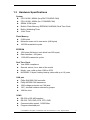
1.3 Hardware Specifications ...............................................................7
Hardware Configuration .........................................................................9
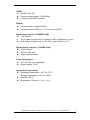
2.1 I-7188XBD-CAN Hardware Structure ............................................9
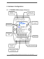
2.2 μPAC-7186EXD-CAN Hardware Structure..................................10
2.3 CAN Network Wire Connection................................................... 11
2.4 Terminal Resistor Jumper Selection ..........................................13
2.5 Wiring Diagram For Different Application..................................14
2.5.1
Program download .........................................................14
2.5.2
General application ........................................................14
2.5.3
I-7188XBD-CAN DI & DO channel wiring diagram .......16
XC100 Library........................................................................................17
3.1 Library Function Definition and Description .............................19
3.1.1
CAN_Reset......................................................................20
3.1.2
XC100Init .........................................................................21
3.1.3
SetCANBaud ...................................................................26
3.1.4
SetCANMask ...................................................................27
3.1.5
CAN_InstallIrq.................................................................28
3.1.6
CAN_RemoveIrq .............................................................29
3.1.7
CAN_Resotre ..................................................................30
3.1.8
CAN_CreateBuffer ..........................................................31
3.1.9
SendCANMsg..................................................................32
3.1.10 GetCANMsg ....................................................................34
3.1.11
GetStatus.........................................................................36
3.1.12 ClearStatus......................................................................37
3.1.13 L1Off ................................................................................38
3.1.14 L2Off ................................................................................39
3.1.15 L3Off ................................................................................40
3.1.16 L1On ................................................................................41
3.1.17 L2On ................................................................................42
3.1.18 L3On ................................................................................43
3.1.19 UserCANInt .....................................................................44
3.1.20 CAN_SearchBaud...........................................................46
3.2 Table of Return Code...................................................................48
I-7188XBD-CAN/μPAC-7186EXD-CAN user manual (ver.1.0.2, July/14/2007)
2
4
Demo Programs ....................................................................................49
4.1 Program Download Procedure ...................................................51
I-7188XBD-CAN/μPAC-7186EXD-CAN user manual (ver.1.0.2, July/14/2007)
3
1 Introduction
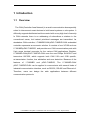
1.1 Overview
The CAN (Controller Area Network) is a serial communication bus especially
suited to interconnect smart devices to build smart systems or sub-system. It
efficiently supports distributed real-time control with a very high level of security.
In CAN networks, there is no addressing of subscribers or stations in the
conventional sense, but instead prioritized messages are transmitted. As
standalone CAN controller, I-7188XBD-CAN/μPAC-7186EXD-CAN embedded
controller represents an economic solution. It consists of one XC100 and one
I-7188XBD/μPAC-7186EXD, and provides one CAN communication ports with
5-pin screw terminal connector for the various CAN applications. Besides,
I-7188XBD-CAN/μPAC-7186EXD-CAN uses the new Phillips SJA1000T and
transceiver 82C250, which supports both CAN 2.0A and 2.0B specific,
re-transmission function, bus arbitration and error detection. Because of the
features
of
I-7188XBD
and
μPAC-7186EXD,
The
I-7188XBD-CAN/
μPAC-7186EXD-CAN can be applied to communicate with several kinds of
industrial communication interface, such as RS-232, RS-485 and Ethernet of.
Therefore, users can design the wide applications between different
communication protocols.
I-7188XBD-CAN/μPAC-7186EXD-CAN user manual (ver.1.0.2, July/14/2007)
4
I-7188XBD-CAN/μPAC-7186EXD-CAN user manual (ver.1.0.2, July/14/2007)
5
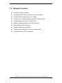
1.2 Hardware Features
1000Vdc voltage protection.
Compatible with CAN specification 2.0 parts A and B.
Programmable transfer rate up to 1 Mbps.
Jumper select 120Ω terminator resistor for CAN channel
Programmable with the XC100 library file.
Allow to design the behavior of CAN controller
Multi communication interface
Support Watchdog mechanism
Programmable Interrupt service routine and timers
Programmable by C/C++ language
I-7188XBD-CAN/μPAC-7186EXD-CAN user manual (ver.1.0.2, July/14/2007)
6
1.3 Hardware Specifications
System
CPU: 80186, 80MHz (for μPAC-7186EXD-CAN)
CPU: 80188, 40MHz (for I-7188XBD-CAN)
SRAM: 512K bytes
Build-in Flash Memory, EEPROM, NVSRAM, Real Time Clock
Built-in Watchdog Timer
16-bit Timer
Flash Memory
512K bytes
Minimum erase unit is one sector (64K bytes)
100,000 erase/write cycles
EEPROM
16K bytes (64 blocks, each block has 256 bytes)
Data retention >100 years
1,000,000 erase/write cycles
Real Time Clock
Year-2000 compliance
Second, minute, hour, date of the month
Month, year, valid up from 1980 to 2079
NVSRAM: 31 bytes, battery backup, data valid up to 10 years
CAN port
Philip SJA1000 CAN controller
Philip 82C250 CAN transceiver
1000 voltage protection on CAN side
120Ω terminal resister selected by jumper
16M Hz clock
COM1
RS-232 or RS-485 Interface
RS-232: TXD, RXD, RTS, CTS, GND
Communication speed: 115200 Max.
Program download port
I-7188XBD-CAN/μPAC-7186EXD-CAN user manual (ver.1.0.2, July/14/2007)
7
COM2
RS-485: D2+, D2Communication speed: 115200 Max.
Connect to DCON IO modules
Display
Programmable 7-segment LEDs
Programmable 4 LEDs (L1, L2, L3 and round LED)
Digital Input (only for I-7188XBD-CAN)
1 DI channel
Dry Contact: Logical level 0: closed to GND, Logical level 1: open
Wet contact: Logical level 1:3.5V~30V, Logical level 0: 0~1V
Digital Output (only for I-7188XBD-CAN)
1 DO channel
100 mA, 30V max.
Open-collector output
Power Requirement
10 to 30 VDC (non-regulated)
Power Supply: 3.0W
Application Environment
Operating Temperature: -25°C to +75°C
Storage Temperature: -30°C to +85°C
Humidity: 5%~9
Dimensions: 123mm*64.5mm*19.6mm
I-7188XBD-CAN/μPAC-7186EXD-CAN user manual (ver.1.0.2, July/14/2007)
8
2 Hardware Configuration
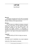
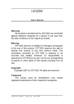
2.1 I-7188XBD-CAN Hardware Structure
CAN Bus
Connector
Bypass CAN
Bus Connector
L1, L2, and
L3 LEDs
Round LED
7-segment
LED
Power Pin
DO and DI
channel
COM2: RS-485 Port
COM1: RS-232 Port
or RS-485 Port
I-7188XBD-CAN/μPAC-7186EXD-CAN user manual (ver.1.0.2, July/14/2007)
9
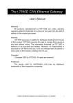
2.2 μPAC-7186EXD-CAN Hardware Structure
CAN Bus
Connector
Bypass CAN
Bus Connector
L1, L2, and
L3 LEDs
Round LED
7-segment
LED
Power Pin
Ethernet port
COM2: RS-485 Port
COM1: RS-232 Port
I-7188XBD-CAN/μPAC-7186EXD-CAN user manual (ver.1.0.2, July/14/2007)
10
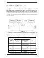
2.3 CAN Network Wire Connection
In order to minimize the reflection effects on the CAN bus line, the CAN
bus line has to be terminated at both ends by two terminal resistances as
following figure. According to the ISO 11898-2 spec, each terminal resistance
is 120Ω (or between 108Ω~132Ω). The length related resistance should have
70 mΩ/m. The user should check the resistances of CAN bus, before install a
new CAN network.
Moreover, in order to minimize the voltage drop on long distance, the
terminal resistance should be higher than the value defined in the ISO 11898-2.
The following table could be a reference.
Bus Cable Parameters
Bus Length
(meter)
Length Related
Resistance
(mΩ/m)
0~40
70
40~300
< 60
300~600
< 40
600~1K
< 20
Cross Section
(Type)
0.25(23AWG)~
0.34mm2(22AWG)
0.34(22AWG)~
0.6mm2(20AWG)
0.5~0.6mm2
(20AWG)
0.75~0.mm2
(18AWG)
Terminal
Resistance
(Ω)
124 (0.1%)
127 (0.1%)
150~300
150~300
I-7188XBD-CAN/μPAC-7186EXD-CAN user manual (ver.1.0.2, July/14/2007)
11
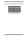
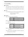
The CAN bus bard rate has the high relationship with the bus length. The
following table indicates the corresponding bus length on every kind of baud
rate.
Baud rate (bit/s)
1M
800 K
500 K
250 K
125 K
50 K
20 K
10 K
Max. Bus length (m)
25
50
100
250
500
1000
2500
5000
Note: When the bus length is greater than 1000m, the
bridge or repeater devices may be needed.
I-7188XBD-CAN/μPAC-7186EXD-CAN user manual (ver.1.0.2, July/14/2007)
12
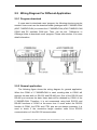
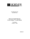
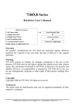
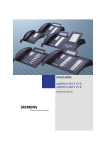
2.4 Terminal Resistor Jumper Selection
J3
J4
CAN
controller
CAN
transceiver
clock
Figure2.1
LED2 LED1 LED0
XC100
Remove the cover of the I-7188XBD-CAN/μPAC-7186EXD-CAN. users
can see the part of internal structure shown as following figure. The XC100
provides users one jumper-selected termination resistor (J3). Its position is
displayed below.
XC100 I/O expansion board LAYOUT
The jumper J3 is used to judge the resister of CAN network. When users
want to set the jumper JP3, the upper cover of I-7188XBD-CAN/
μPAC-7186EXD-CAN needs to be removed. About the J3 jumper setting,
please refer the following figure.
Apply the termination
Don’t apply the termination resistor
resistor(120Ω)
Table 2.1
For(I-7188XBD-CAN)
Table 2.2
J3 Jumper Selections
For(μPAC-7186EXD-CAN)
J4 Jumper Selections
I-7188XBD-CAN/μPAC-7186EXD-CAN user manual (ver.1.0.2, July/14/2007)
13
2.5 Wiring Diagram For Different Application
2.5.1 Program download
If users want to download users’ program, the following structure may be
needed. Users must use the download cable (packaged with I-7188XBD-CAN/
μPAC-7186EXD-CAN) to connect the I-7188XBD-CAN/ μPAC-7186EXD-CAN
COM1 with PC available COM port. Then, use the tool, 7188xw.exe, in
OSImage folder to download users’ program. Please refer section 4 for more
detail information.
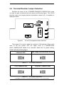
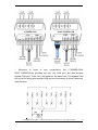
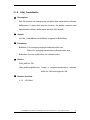
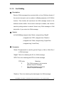
2.5.2 General application
The following figure shows the wiring diagram for general application.
When the COM1 of I-7188XBD-CAN is used, sending data to COM1 will
transmit the data both on RS-232 and RS-485 port. One of the RS-232 and
RS-485 port receives the data, these data will be obtained by COM1 of the
I-7188XBD-CAN. Therefore, it is not recommend using both RS-232 and
RS-485 functions of COM1 at the same time. If users select the RS-232
function of COM1, the RTS1 and CTS1 pins are not always necessary. It is
need to check if the connection target machine uses 3-line RS-232
communication or 5-line RS-232 communication.
I-7188XBD-CAN/μPAC-7186EXD-CAN user manual (ver.1.0.2, July/14/2007)
14
A
_
A
Moreover, in order to wire conveniently, the I-7188XBD-CAN/
μPAC-7186EXD-CAN provides not only one CAN port, but also another
bypass CAN port. There two CAN ports are the same one. The bypass CAN
port is just for wiring with another CAN device conveniently, it doesn’t have any
other function.
Ω
0
2
1
3
JP
I-7188XBD-CAN/μPAC-7186EXD-CAN user manual (ver.1.0.2, July/14/2007)
15
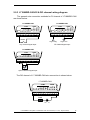
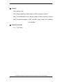
2.5.3 I-7188XBD-CAN DI & DO channel wiring diagram
The general wire connection methods for DI channel of I-7188XBD-CAN
are shown below.
I-7188XBD-CAN
I-7188XBD-CAN
COM1
COM1
COM2
DO
DI
D1+
D1CTS1
RTS1
GND
TXD1
RXD1
INIT*
(Y)D2+
(G)D2(R)VS+
(B)GND
DO
DI
D1+
D1CTS1
RTS1
GND
TXD1
RXD1
INIT*
(Y)D2+
(G)D2(R)VS+
(B)GND
COM2
Switch
Logic Hihg
Dry Contact Signal Input
Logic Low
TTL/CMOS Signal Input
I-7188XBD-CAN
COM1
DO
DI
D1+
D1CTS1
RTS1
GND
TXD1
RXD1
INIT*
(Y)D2+
(G)D2(R)VS+
(B)GND
COM2
Open-Collector Signal Input
The DO channel of I-7188XBD-CAN wire connection is shown below.
I-7188XBD-CAN
COM1
DO
DI
D1+
D1CTS1
RTS1
GND
TXD1
RXD1
INIT*
(Y)D2+
(G)D2(R)VS+
(B)GND
COM2
Load
V+
V-
d
a
o
L
I-7188XBD-CAN/μPAC-7186EXD-CAN user manual (ver.1.0.2, July/14/2007)
16
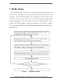
3 XC100 Library
The XC100 library file, XC100L.lib, is useful to help user design various CAN
devices. Here, the library for TC, BC and MSC is provided to receive CAN
messages, transmit CAN messages, and configure the CAN controller. This
section will show you what they have and how to use them. For developing a
program, the figure 3.1 and 3.2 may be a reference. The XC100L.lib is only
used for the XC100 hardware, and is for Large Mode of the C/C++ compiler.
For the step-by-step information about the program procedure, please refer to
the section 4.1.
Figure3.1
Program procedure
I-7188XBD-CAN/μPAC-7186EXD-CAN user manual (ver.1.0.2, July/14/2007)
17
Project file
C/C++ language
source code
XC100L.lib
Compile & Link
Execution file
7188XBL.lib/
7186EL.lib
Figure3.2
Compile concept
Because this manual is special described for the CAN functions, if users
want
to
know
the
other
functions
and
demos
of
the
I-7188XBD-CAN/μPAC-7186EXD-CAN (such as the EEPROM function,
7-segment function, flash ram function, real-time clock function, watchdog
function, com port function, and so forth), please refer to the
I-7188XB(D)/I-7188EX(D) user manual. Or refer to the on-line help on the
7000/7188/8000 CD. In this on-line help, users can find a lot of useful
information about MiniOS7 operation commands, the other functions of
I-7188XBD-CAN/ μPAC-7186EXD-CAN, and the functions of download tool,
7188xw.exe. MiniOS7 is the operation system of the I-7188XBD-CAN/
μPAC-7186EXD-CAN. It is a dos-like operation system. The 7188xw.exe is a
download tool. If users want to download users’ program into the
I-7188XBD-CAN/ μPAC-7186EXD-CAN, this tool may be needed. Users can
find the 7188xw.exe in the uPAC-7186EXD-CAN-OS-Image folder in CAN CD.
It path is “CAN/PAC/uPAC-7186EXD-CAN”. (Note: I-7188EX(D) demos can be used
in the μPAC-7186EXD-CAN. Users just need to compile I-7188EX(D) demos again with
7186EL.lib. Both I-7188XBD-CAN and μPAC-7186EXD-CAN functions can refer to the
following on-line help.)
For on-line help:
8000cd /napdos/7188xabc/7188xb/document/
(For I-7188XBD-CAN)
fieldbus_cd/can/pac/i-7188xbd-can/document
8000cd /napdos/7186e/document/
(For uPAC-7186EXD-CAN)
fieldbus_cd/can/pac/upac-7186exd-can/document/
For demos:
8000cd /napdos/7188xabc/7188xb/demo/
(For I-7188XBD-CAN)
fieldbus_cd/can/pac/i-7188xbd-can/demo/
8000cd /napdos/7186e/demo/ (For uPAC-7186EXD-CAN)
fieldbus_cd/can/pac/upac-7186exd-can/document
I-7188XBD-CAN/μPAC-7186EXD-CAN user manual (ver.1.0.2, July/14/2007)
18
3.1 Library Function Definition and Description
The functions of XC100 library file are presented in the following table. They
are provided to help users construct their characteristic CAN device. For the
detail information of each function, please refer to the following sub-section.
Function definition
CAN_Reset
Description
CAN controller hardware reset
Page
20
XC100Init
SetCANBaud
Initialize the XC100 hardware
Change CAN baud
21
26
SetCANMask
Change CAN message filter
27
CAN_InstallIrq
Enable the embedded controller interrupt
28
CAN_RemoveIrq
Disable the embedded controller interrupt
29
CAN_Restore
Release the resource and disable the
embed controller interrupt
30
CAN_CreateBuffer
Change the reception and transmission
buffer sizes
Send a CAN message to the CAN network
31
34
L1Off
Receive a CAN message
Obtain the CAN controller status and
reception/transmission buffer status
Reset the reception and transmission buffer
status
Turn LED0 off
L2Off
Turn LED1 off
39
L3Off
Turn LED2 off
40
L1On
Turn LED0 on
41
L2On
Turn LED1 on
42
L3On
Turn LED2 on
43
UserCANInt
CAN_SearchBaud
Design user-defined interrupt routine
44
45
SendCANMsg
GetCANMsg
GetStatus
ClearStatus
Table3.1
Search the necessary CAN Bus baud rate
32
36
37
38
The function list of the XC100 library file
I-7188XBD-CAN/μPAC-7186EXD-CAN user manual (ver.1.0.2, July/14/2007)
19
3.1.1 CAN_Reset
Description:
Reset the CAN controller by hardware circuit. After running this function,
the CAN controller will be set to initial state. For more information about
this, please refer to the SJA1000 data sheet on the web site.
http://www.semiconductors.philips.com/pip/SJA1000.html#datasheet
.
Syntax:
void CAN_Reset(void)
Parameter:
None
Return:
None
Relative function:
None
I-7188XBD-CAN/μPAC-7186EXD-CAN user manual (ver.1.0.2, July/14/2007)
20
3.1.2 XC100Init
Description:
Initialize the software buffer and XC100 hardware, which includes CAN
controller, L1 LED, L2 LED and L3 LED.
Syntax:
int XC100Init(int TypeOf7188,char IntMode, unsigned long CANBaud,
char BT0, char BT1,unsigned long AccCode,
unsigned long AccMask)
Parameter:
TypeOf7188: define what kind of module you use.
value
TypeOf7188
0
For I-7188XBD-CAN
1
For μPAC-7186EXD-CAN
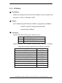
IntMode: Set the CAN controller interrupt mode. Each bit of IntMode
parameters indicates different function shown as follows.
Interrupt Type
Value of IntMode
Receive Interrupt Enable
0x01
Transmit Interrupt Enable
0x02
Error Warning Interrupt Enable
0x04
Data Overrun Interrupt Enable
0x08
Wake-up Interrupt Enable
0x10
Error Passive Interrupt Enable
0x20
Arbitration Lost Interrupt Enable
0x40
Bus Error Interrupt Enable
0x80
I-7188XBD-CAN/μPAC-7186EXD-CAN user manual (ver.1.0.2, July/14/2007)
21
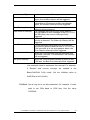
Interrupt Type
Receive Interrupt
Transmit Interrupt
Error Warning Interrupt
Data Overrun Interrupt
Meaning
When a message has been received without
errors, the receive interrupt will be triggered.
When a message has been successfully
transmitted or the transmit buffer is accessible
again, the transmit interrupt will be triggered.
If the error or bus status is set or clear, the error
interrupt will be triggered.
If a message was lost because there was not
enough space for that message in the FIFO (FIFO
has 64 bytes), the overrun interrupt will be
triggered.
Wake-up Interrupt
When the CAN controller is sleeping and bus
activity is detected. The Wake-up interrupt will be
triggered.
Error Passive Interrupt
If CAN controller has at least one error counter
exceeds the protocol-defined level of 127 or if the
CAN controller is in the error passive status, the
Error Passive Interrupt will be triggered.
Arbitration Lost Interrupt When the CAN controller lost the arbitration and
becomes a receiver. The Arbitration Lost Interrupt
will be triggered.
Bus Error Interrupt
When the CAN controller detects an error on the
CAN bus, the Bus Error Interrupt will be triggered.
Use one-byte value to implement the interrupt. For example,
if Receive and overrun interrupt are needed in the
BasicCAN(CAN 2.0A) mode. Set the IntMode value to
0x09(That is 0x01+0x08.).
CANBaud: Use a long int to set this parameter. For example, if users
want to set CAN baud to 125K bps. Use the value
125000UL.
I-7188XBD-CAN/μPAC-7186EXD-CAN user manual (ver.1.0.2, July/14/2007)
22
BT0, BT1: Set the special user-defined baud rate. Users can set
arbitrary baud with these parameters. But users need to
have the background of SJA1000 CAN controller and
82C251 CAN transceiver, and calculate the values of BT0
and BT1 by themselves (The clock frequency of CAN
controller is 16MHz.).
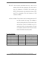
AccCode, AccMask: The AccCode is used for deciding what kind of ID
the CAN controller will accept. The AccMask is
used for deciding which bit of ID will need to check
with AccCode. If the bit of AccMask is set to 0, it
means that the bit in the same position of ID need
to be checked, and the bit value ID need to match
the bit of AccCode in the same position.
For 11-bit ID Message:
Register
bits of register
Filter Target
AccCode[0] and AccMask[0]
bit7~bit0
bit10 ~ bit3 of ID
AccCode[1] and AccMask[1]
bit7~bit5
bit2 ~ bit0 of ID
AccCode[1] and AccMask[1]
bit4
RTR
AccCode[1] and AccMask[1]
bit3~bit0
no use
AccCode[2] and AccMask[2]
bit7~bit0
bit7 ~ bit0 of 1st byte data
AccCode[3] and AccMask[3]
bit7~bit0
bit7 ~ bit0 of 2nd byte data
I-7188XBD-CAN/μPAC-7186EXD-CAN user manual (ver.1.0.2, July/14/2007)
23
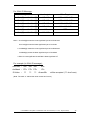
For 29-bit ID Message:
Register
bits of register
Filter Target
AccCode[0] and AccMask[0]
bit7~bit0
bit28 ~ bit21 of ID
AccCode[1] and AccMask[1]
bit7~bit0
bit20 ~ bit13 of ID
AccCode[2] and AccMask[2]
bit7~bit0
bit12 ~ bit5 of ID
AccCode[3] and AccMask[3]
bit7~bit3
bit4 ~ bit0 of ID
AccCode[3] and AccMask[3]
bit2
RTR
AccCode[3] and AccMask[3]
bit1~bit0
no use
Note: 1. AccCode[0] means the most significant byte of AccCode and
AccCode[3] means the least significant byte of AccCode.
2. AccMask[0] means the most significant byte of AccMask and
AccMask[3] means the least significant byte of AccMask.
3. Bit10 is most significant bit and Bit0 is least significant bit
For example (In 29 bit ID message):
AccCode : 00h
00h
00h
A0h
AccMask : FFh
FFh FFh
1Fh
ID Value
:
??
??
??
Ah and Bh
will be accepted. (??: don't care)
(Note: The mark “h” behind the value means hex format.)
I-7188XBD-CAN/μPAC-7186EXD-CAN user manual (ver.1.0.2, July/14/2007)
24
Return:
CAN_NoError: OK
CAN_BaudNotSupport: This CAN baud rate is not support.
CAN_ResetError: Fail to reset the CAN controller.
CAN_ConfigError: Fail to configure the CAN controller register.
CAN_SetACRError: Fail to set the AccCode register
CAN_SetAMRError: Fail to set the AccCode register
CAN_NotEnoughMemory: Create a reception/transmission software
buffer for CAN messages are fail.
CAN_TypeOf7188Error: The type of the 7188 is not defined of this
library.
Relative function:
None
I-7188XBD-CAN/μPAC-7186EXD-CAN user manual (ver.1.0.2, July/14/2007)
25
3.1.3 SetCANBaud
Description:
This function is used to change the CAN baud after calling XC100init
function.
Syntax:
int SetCANBaud(unsigned long CANBaud, char BT0, char BT1)
Parameter:
CANBaud, BT0, BT1: Please refer to the parameters description in the
XC100Init function in section 3.1.2.
Return:
CAN_NoError: OK
CAN_BaudNotSupport: This CAN baud rate is not supported.
CAN_ResetError: CAN controller can’t enter the reset mode. So, all
parameters can’t be set normally.
Relative function:
3.1.2
XC100Init
I-7188XBD-CAN/μPAC-7186EXD-CAN user manual (ver.1.0.2, July/14/2007)
26
3.1.4 SetCANMask
Description:
This function is used to change the CAN message filter after using
XC100init function.
Syntax:
int SetCANMask(unsigned long AccCode, unsigned long AccMask)
Parameter:
AccCode, AccMask: Please refer to the parameters description in the
XC100Init function in section 3.1.2.
Return:
CAN_NoError: OK
CAN_ResetError: Fail to reset the CAN controller.
CAN_SetACRError: Fail to set the AccCode register
CAN_SetAMRError: Fail to set the AccCode register
Relative function:
3.1.2
XC100Init
I-7188XBD-CAN/μPAC-7186EXD-CAN user manual (ver.1.0.2, July/14/2007)
27
3.1.5 CAN_InstallIrq
Description:
Set the interrupt function enable. Afterwards, the CPU of I-7188 series
embedded controller can receive the interrupt signal from CAN
controller.
Syntax:
void CAN_InstallIrq(void)
Parameter:
None
Return:
None
Relative function:
3.1.6
CAN_RemoveIrq
I-7188XBD-CAN/μPAC-7186EXD-CAN user manual (ver.1.0.2, July/14/2007)
28
3.1.6 CAN_RemoveIrq
Description:
Disable the interrupt function. Afterwards, the CPU of I-7188 series
embedded controller can't receive the interrupt signal from CAN
controller.
Syntax:
void CAN_RemoveIrq(void)
Parameter:
None
Return:
None
Relative function:
3.1.5
CAN_InstallIrq
I-7188XBD-CAN/μPAC-7186EXD-CAN user manual (ver.1.0.2, July/14/2007)
29
3.1.7 CAN_Resotre
Description:
Set the interrupt function disable, release all software buffer, and reset
CAN chip. This function must be called to release resource before the
program is terminated.
Syntax:
void CAN_Restore(void)
Parameter:
None
Return:
None
Relative function:
None
I-7188XBD-CAN/μPAC-7186EXD-CAN user manual (ver.1.0.2, July/14/2007)
30
3.1.8 CAN_CreateBuffer
Description:
Call this function for changing the reception and transmission software
buffer sizes. If users don't use this function, the default reception and
transmission software buffer sizes are both 256 records.
Syntax:
int CAN_CreateBuffer(int BufMode, unsigned int BufferSize)
Parameter:
BufMode: 0 for changing reception software buffer size.
Others for changing transmission software buffer size.
BufferSize: the new buffer sizes for software buffer.
Return:
CAN_NoError: OK
CAN_NotEnoughMemory: Create a reception/transmission software
buffer for CAN messages are fail.
Relative function:
3.1.2
XC100Init
I-7188XBD-CAN/μPAC-7186EXD-CAN user manual (ver.1.0.2, July/14/2007)
31
3.1.9 SendCANMsg
Description:
If the transmit buffer is disable, this function will send a message to the
CAN network. However, if the transmit buffer is enable, this function will
send all the messages stored in the transmit buffer to the CAN network.
Syntax:
int SendCANMsg(unsigned char Mode,unsigned long MsgID, unsigned
char RTR, unsigned char DataLen,
unsigned char *Data)
Parameter:
Mode: This parameter is used for CAN ID type.
Mode value
Meaning
0
Send a 11-bit ID CAN message
others
Send a 29-bit ID CAN message
MsgID: The ID of this CAN message. The ID may be a 11-bit value or
29-bit value.
RTR: Remote transmits request byte.
RTR value
Meaning
0
This CAN message is not a remote
transmit request message.
1
This CAN message is a remote
transmit request message.
DataLen: The pure data length of a CAN messages. The range of this
value is 0~8.
*Data: Store the data of CAN message. The numbers of data bytes
need to match with the "DataLen".
I-7188XBD-CAN/μPAC-7186EXD-CAN user manual (ver.1.0.2, July/14/2007)
32
Return:
CAN_NoError: OK
CAN_DataLengthError: Data length of CAN message is over 8.
CAN_TransmitBufferLocked: Transmit buffer of CAN controller is locked.
CAN_TransmitIncomplete: CAN controller can't send the message
successfully.
Relative function:
3.1.2
XC100Init
I-7188XBD-CAN/μPAC-7186EXD-CAN user manual (ver.1.0.2, July/14/2007)
33
3.1.10
GetCANMsg
Description:
Receive CAN messages from receive buffer or from CAN bus directly. If
the receive interrupt is set to enable in IntMode parameter of XC100Init
function. This function will read back the CAN message stored in the
software receive buffer. If the receive interrupt is disable, this function
uses the polling method to check if there is any CAN message in CAN
chip buffer. If yes, return the CAN message.
Syntax:
int GetCANMsg(unsigned char *Mode, unsigned long *MsgID
, unsigned char *RTR, unsigned char *DataLen
, unsigned char *Data, unsigned long *UpperTime
, unsigned long *LowerTime)
Parameter:
*Mode: This parameter is used for get the ID type (11-bit or 29-bit ID) of
a CAN message.
*MsgID: This is for obtaining the ID of a CAN message.
*RTR: This is for obtaining the RTR of a CAN message.
RTR value
Meaning
0
This CAN message is not a remote
transmit request message.
1
This CAN message is a remote
transmit request message.
*DataLen: This is for obtaining the data length of a CAN message.
I-7188XBD-CAN/μPAC-7186EXD-CAN user manual (ver.1.0.2, July/14/2007)
34
*Data: This is for obtaining the Data of a CAN message. The Data buffer
size must be 8 bytes.
*UpperTime: Get the time stamp of a CAN message. The time stamp
unit is us (micro second), This parameter only show the
upper part of time stamp.
Real time stamp = upper part * 0x1000000UL+lower part
*LowerTime: Get the lower part of time stamp of a CAN message.
Return:
CAN_NoError: OK
CAN_ReceiveBufferEmpty: No message is in the CAN receive buffer.
CAN_SoftBufferIsEmpty: No message is in the software receive buffer.
CAN_DataLengthError: The Data length of received message is over
than 8.
Relative function:
3.1.2
XC100Init
I-7188XBD-CAN/μPAC-7186EXD-CAN user manual (ver.1.0.2, July/14/2007)
35
3.1.11
GetStatus
Description:
Read the CAN controller status and software buffer overflow flag
message.
Syntax:
void GetStatus(unsigned char *CANReg, unsigned char *OverflowFlag)
Parameter:
* CANReg: The pointer for obtain the current CAN controller status. For
the information about the CANReg value meaning, please
refer to the following table.
Bit NO.
Description
7 (MSB) Bus status. 1 for bus off, 0 for bus on.
6
Error status. 1 for at least one error, 0 for OK.
5
Transmit status. 1 for transmitting, 0 for idle.
4
Receive status. 1 for receiving, 0 for idle.
3
Transmit complete status. 1 for complete, 0 for incomplete.
2
Transmit buffer status. 1 for released, 0 for locked
1
Data overrun status. 1 for reception buffer overrun, 0 for OK.
0 (LSB)
Receive buffer status. 1 for at least one message stored in the
reception buffer, 0 for empty.
* OverflowFlag: CAN reception and transmission overflow flag information
For the information about the OverflowFlag value
meaning, please refer to the following table.
Bit NO.
Description
Others
Reserved
1
1 for reception software buffer overflow. 0 for normal.
0 (LSB) 1 for transmission software buffer overflow. 0 for normal.
Return:
None
Relative function:
3.1.12
ClearStatus
I-7188XBD-CAN/μPAC-7186EXD-CAN user manual (ver.1.0.2, July/14/2007)
36
3.1.12
ClearStatus
Description:
This function is used for cleaning the CAN reception or transmission
software buffer overflow flag. When one of these two buffers is full, the
corresponding overflow flag will be set to 1. In this case, users need to
use this function to clear the overflow flag to acknowledge the error
information.
Syntax:
void ClearStatus(void)
Parameter:
None
Return:
None
Relative function:
3.1.11 GetStatus
I-7188XBD-CAN/μPAC-7186EXD-CAN user manual (ver.1.0.2, July/14/2007)
37
3.1.13
L1Off
Description:
Turn the L1 LED off. About the position of L1 LED, please refer to the
figure 2.1 in the section 2.1.
Syntax:
void L1Off(void)
Parameter:
None
Return:
None
Relative function:
3.1.16
L1On
I-7188XBD-CAN/μPAC-7186EXD-CAN user manual (ver.1.0.2, July/14/2007)
38
3.1.14
L2Off
Description:
Turn the L2 LED off. About the position of L2 LED, please refer to the
figure 2.1 in the section 2.1.
Syntax:
void L2Off(void)
Parameter:
None
Return:
None
Relative function:
3.1.17
L2On
I-7188XBD-CAN/μPAC-7186EXD-CAN user manual (ver.1.0.2, July/14/2007)
39
3.1.15
L3Off
Description:
Turn the L3 LED off. About the position of L3 LED, please refer to the
figure 2.1 in the section 2.1.
Syntax:
void L3Off(void)
Parameter:
None
Return:
None
Relative function:
3.1.18
L3On
I-7188XBD-CAN/μPAC-7186EXD-CAN user manual (ver.1.0.2, July/14/2007)
40
3.1.16
L1On
Description:
Turn the L1 LED on. About the position of L1 LED, please refer to the
figure 2.1 in the section 2.1.
Syntax:
void L1On(void)
Parameter:
None
Return:
None
Relative function:
3.1.13
L1Off
I-7188XBD-CAN/μPAC-7186EXD-CAN user manual (ver.1.0.2, July/14/2007)
41
3.1.17
L2On
Description:
Turn the L2 LED on. About the position of L2 LED, please refer to the
figure 2.1 in the section 2.1.
Syntax:
void L2On(void)
Parameter:
None
Return:
None
Relative function:
3.1.14
L2Off
I-7188XBD-CAN/μPAC-7186EXD-CAN user manual (ver.1.0.2, July/14/2007)
42
3.1.18
L3On
Description:
Turn the L3 LED on. About the position of L3 LED, please refer to the
figure 2.1 in the section 2.1.
Syntax:
void L3On(void)
Parameter:
None
Return:
None
Relative function:
3.1.15
L3Off
I-7188XBD-CAN/μPAC-7186EXD-CAN user manual (ver.1.0.2, July/14/2007)
43
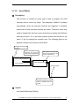
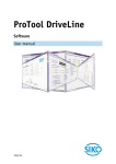
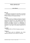
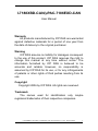
3.1.19
UserCANInt
Description:
This function is created by users and is used to program the CAN
interrupt service routine by users. The parameter CANINT is passed
automatically when the interrupt functions are triggered. It indicates
what kinds of CAN controller interrupt are active. Therefore, users only
need to design their interrupt routine according to dealing with different
interrupt functions. If it is not used, please reverse this function in the
users’ .C file for avoiding the complier error. The following figure is the
general concept of the function UserCANInt.
program running
sequence
When interrupts are
triggered, the interrupt
routine will be inplemented
...
CAN_Config(&ConfigInfo);
...
...
CAN_Restore();
main program
The types of interrupt
function are passed into the
function UserInterrupt
...
UserCANInt(CANInt);
...
interrupt routine
void UserCANInt(char CANInt)
{
...
switch (CANInt)
{
...
}
...
}
user-defined function
Use switch function or other
methods to design the action
based on different types of
interrupt.
Syntax:
void UserCANInt(char CANInt)
I-7188XBD-CAN/μPAC-7186EXD-CAN user manual (ver.1.0.2, July/14/2007)
44
Parameter:
CANInt: The interrupt service routine will bypass the CANInt parameter
to users to indicate what interrupt is triggered. For the meanings of
CANInt parameters, please refer to the following table.
CANIntMode Value (Hex)
Meaning
0x01
Receive a message successfully
0x02
Transmit a message successfully
0x04
Error warring
0x08
Data Overrun
0x10
CAN controller wake-up
0x20
Bus Passive
0x40
Arbitration Lost
0x80
Bus Error
Return:
None
Relative function:
3.1.2
XC100Init
I-7188XBD-CAN/μPAC-7186EXD-CAN user manual (ver.1.0.2, July/14/2007)
45
3.1.20
CAN_SearchBaud
Description:
Enter “Listen Only Mode” and enable receive and error interrupt to
detect the right bit-rate of the CAN bus. Upon successful reception of a
message, the “CAN_NoError” message will be return. Otherwise, the
“CAN_AutoBaudTimeout” message will be return
Syntax:
int CAN_SearchBaud(unsigned long CANBaud, char BT0, char
BT1,unsigned int Timeout)
Parameter:
CANBaud: Use a long int to set this parameter. For example, if users
want to set CAN baud to 125K bps. Use the value
125000UL.
BT0, BT1: Set the special user-defined baud rate. Users can set
arbitrary baud with these parameters. But users need to have the
background of SJA1000 CAN controller and 82C251 CAN
transceiver, and calculate the values of BT0 and BT1 by
themselves (The clock frequency of CAN controller is 16MHz.)
Timeout:
Set the timer for search a necessary CAN bus baud rate.
I-7188XBD-CAN/μPAC-7186EXD-CAN user manual (ver.1.0.2, July/14/2007)
46
Return:
CAN_NoError: OK.
CAN_ResetError:
Fail to reset the CAN controller.
CAN_ConfigError: Fail to Configure the CAN controller register.
CAN_SetBaudRateError:
Fail to set the CAN baud rate.
CAN_BaudNotSupport: The baud rate is not support.
CAN_AutoBaudTimeout: Can’t find the necessary CAN bus baud rate.
Relative function:
None
I-7188XBD-CAN/μPAC-7186EXD-CAN user manual (ver.1.0.2, July/14/2007)
47
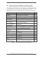
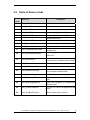
3.2 Table of Return Code
Return
Code
Error ID
Comment
0
CAN_NoError
OK
5
CAN_ResetError
Enter reset mode error
8
CAN_ConfigError
CAN chip configure error
9
CAN_SetACRError
Set to Acceptance Code Register error
10
CAN_SetAMRError
Set to Acceptance Mask Register error
11
CAN_SetBaudRateError
14
CAN_InstallIrqFailure
Set Baud Rate error
Enable interrupt functions failure
15
CAN_RemoveIrqFailure
Disable interrupt functions failure
16
CAN_TransmitIncomplete
17
CAN_TransmitBufferLocked
18
CAN_ReceiveBufferEmpty
Data can’t be transmitted successfully
Previously
transmission
is
not
completed yet
No message is stored in the receive
19
CAN_DataOverrun
20
CAN_ReceiveError
Receive data is not completed
21
CAN_SoftBufferIsFull
22
CAN_SoftBufferIsEmpty
Software transmit buffer is full
There is no message stored in the
23
CAN_BaudNotSupport
This Baud Rate is not supported
24
CAN_DataLengthError
25
CAN_NotEnoughMemory
Data length doesn’t match the total data
bytes
There is not enough memory space to
create the reception or transmission
software buffer.
26
CAN_TypeOf7188Error
The type of 7188 is not defined by this
library
50
CAN_AutoBaudTimeout
CAN bus baud rate not found
buffer now
Data was lost because there was not
enough space in software receive buffer
user-declared software buffer
I-7188XBD-CAN/μPAC-7186EXD-CAN user manual (ver.1.0.2, July/14/2007)
48
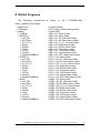
4 Demo Programs
The
following
architecture
is
shown
in
the
I-7188XBD-CAN
/
uPAC-7186EXD-CAN folder.
|--\document
|--\OSimage
|--\demo
|--\LIB100
|--\BCPP31
|--\AC_AM
|--\All_Demo
|--\L1_L2_L3
|--\RxInt
|--\RxPoll
|--\TxInt
|--\TxPoll
|--\UserInt
|--\SearchCANBaud
|--\TCPP31
|--\AC_AM
|--\All_Demo
|--\L1_L2_L3
|--\RxInt
|--\RxPoll
|--\TxInt
|--\TxPoll
|--\UserInt
|--\SearchCANBaud
|--\MSC
|--\AC_AM
|--\All_Demo
|--\L1_L2_L3
|--\RxInt
|--\RxPoll
|--\TxInt
|--\TxPoll
|--\UserInt
|--\SearchCANBaud
Users manual
OS image used for testing demo
demo folier
BC++3.1 library folder
BC++3.1 demo folder
BC++3.1 AC_AM demo folder
BC++3.1 All_Demo demo folder
BC++3.1 L1_L2_L3 demo folder
BC++3.1 RxInt demo folder
BC++3.1 RxPoll demo folder
BC++3.1 TxInt demo folder
BC++3.1 TxPoll demo folder
BC++3.1 UserInt demo folder
BC++3.1 SCH_Baud demo folder
TC++1.01 demo folder
TC++1.01 AC_AM demo folder
TC++1.01 All_Demo demo folder
TC++1.01 L1_L2_L3 demo folder
TC++1.01 RxInt demo folder
TC++1.01 RxPoll demo folder
TC++1.01 TxInt demo folder
TC++1.01 TxPoll demo folder
TC++1.01 UserInt demo folder
TC++1.01 SCH_Baud demo folder
MSC 1.52 demo folder
MSC 1.52 AC_AM demo folder
MSC 1.52 All_Demo demo folder
MSC 1.52 L1_L2_L3 demo folder
MSC 1.52 RxInt demo folder
MSC 1.52 RxPoll demo folder
MSC 1.52 TxInt demo folder
MSC 1.52 TxPoll demo folder
MSC 1.52 UserInt demo folder
MSC 1.52 SCH_Baud demo folder
I-7188XBD-CAN/μPAC-7186EXD-CAN user manual (ver.1.0.2, July/14/2007)
49
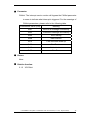
Here, the demo programs of XC100 library file with BC++3.1, TC++1.01
and MSC 1.52 are provided. The content of each demo is displayed in the
following table. When users want to compile the demo program, please move
the demo folder into a new folder named with max 8 letters. The
BC++3.1/TC++1.01/MSC6 compilers are 16-bit compilers and may have a
trouble because of the long file name. The μPAC-7186EXD-CAN folder
architecture is similar as the I-7188XBD-CAN folder architecture. Therefore, if
users use μPAC-7186EXD-CAN the similar architecture described above will
be seen.
Demo
AC_AM
All_Demo
L1_L2_L3
RxInt
RxPoll
TxInt
Content
Use the AccCode and AccMask
Demo the total functions provided by the XC100L.lib.
Use the L1, L2, and L3 LEDs.
Receive the CAN messages by interrupt mode
Receive the CAN messages by polling mode
Send the CAN messages to the CAN network by interrupt
mode.
TxPoll
Send the CAN messages to the CAN network by polling
mode.
UserInt
Use the UserCANInt function to apply the users' CAN interrupt
service routine.
SCH_Baud Demo for search the CAN bus baud rate
In order to introduce users to use the XC100 library file clearly, there is a
step-by-step procedure in the following section. It can give a good model to
show how to build an execution file with XC100L.lib, download the users’
program, and run it on the I-7188XBD-CAN/μPAC-7186EXD-CAN.
I-7188XBD-CAN/μPAC-7186EXD-CAN user manual (ver.1.0.2, July/14/2007)
50
4.1 Program Download Procedure
Here, it is considered that how to build an execution file with XC100L.lib
and how to run this program on the I-7188XBD-CAN/μPAC-7186EXD-CAN.
Step1: Create a folder named “MyDemo” in the C disk.
Step2: Copy the lib folder from the lib100 folder and users program into the
MyDemo folder.
I-7188XBD-CAN/μPAC-7186EXD-CAN user manual (ver.1.02, July/14/2008) ------51
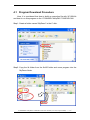
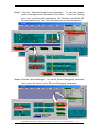
Step3: Run the TC++1.01 development environment. Click the “Options\Full
menus” to expand the all functions of menus. Users can free download
the TC++1.01 from the following web site.
http://comsmunity.borland.com/museum
Step4: Click the “Project\Open project…” to create a new project named
“AC_AM.PRJ”.
I-7188XBD-CAN/μPAC-7186EXD-CAN user manual (ver.1.02, July/14/2008) ------52
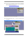
Step5: Search all library file by setting *.lib in the Name filed. Then, use the
“Add” function to add the library file “XC100L.lib” into MyDemo project.
Step6: Following the step5 to add another two files. One is “7188XBL.lib”. If
users use the μPAC-7186EXD-CAN, the library file is “7186EL.lib”.
Another one is users’ C source code file. Here, we use the file
AC_AM.c.
I-7188XBD-CAN/μPAC-7186EXD-CAN user manual (ver.1.02, July/14/2008) ------53
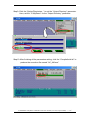
Step7: Click the “Options/Compiler/Code generation…” to set the compile
mode to the large mode. Afterwards, click “More…” to set the “Floating
point” and “Instruction Set” parameters. The Emulation and 80186 will
be used respectively. Then, click OK button to save the configuration.
Step8: Click the “Option/Debugger...” to set the “Source Debugging” parameter.
Here, select the “None” for the “Source Debugging” parameter.
I-7188XBD-CAN/μPAC-7186EXD-CAN user manual (ver.1.02, July/14/2008) ------54
Step9: Click the “Option/Directories...” to set the “Output Directory” parameter.
Here, set the “C:\MyDemo” for the “Output Directory” parameter.
Step10: After finishing all the parameters setting, click the “Compile/build all” to
produce the execution file named “AC_AM.exe”.
I-7188XBD-CAN/μPAC-7186EXD-CAN user manual (ver.1.02, July/14/2008) ------55
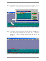
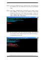
Step11: Copy the file 7188xw.exe into the MyDemo folder. Then, double-click
the 7188xw.exe file. The 7188xw.exe can be found in the OSimage
folder.
Step12: If the COM1 I-7188XBD-CAN is connected to the PC COM1, the hint
sign,”I-7188XB>”, will be shown in the 7188xw.exe window after
pressing the Enter key in the 7188xw.exe program. If users use
μPAC-7186EXD-CAN COM1 to connect the PC COM1, the hint sign,
“uPAC-7186EXD_UDP”, will be shown.
Step13: Key the command, “load” in the 7188xw.exe program. Then, follow the
hint command to press “Alt+E” and input the file name, “AC_AM.exe “,
to download the execution file.
I-7188XBD-CAN/μPAC-7186EXD-CAN user manual (ver.1.02, July/14/2008) ------56
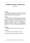
Step14: After finishing the download procedure, key in the command, “run”, to
implement the execution file,”AC_AM.exe”.
I-7188XBD-CAN/μPAC-7186EXD-CAN user manual (ver.1.02, July/14/2008) ------57