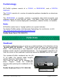
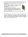
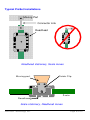
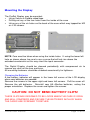
1
ProSet™
User Manual
Firmware V2.0 and Higher
Warranty
Accurate Technology, Inc., warrants the ProSet against defective parts and
workmanship for 3 years commencing from the date of original purchase. Upon
notification of a defect, Accurate Technology, Inc., shall have the option to
repair or replace any defective part. Such services shall be the customer's sole
and exclusive remedy.
Expenses incidental to repair, maintenance, or
replacement under warranty, including those for labor and material, shall be
borne by Accurate Technology, Inc. (Including freight or transportation charges
during the first 30 days).
Except as expressly provided in this warranty, Accurate Technology, Inc., does
not make any warranties with respect to the product, either expressed or
implied, including implied warranties of merchantability or fitness for a particular
purpose, except as expressly provided in this agreement.
Accurate Technology, Inc., shall not be liable for any special, incidental, or
consequential damages or for loss, damage or expense directly or indirectly
arising from the customer's use of or inability to use the equipment either
separately or in combination with other equipment, or for personal injury or loss
or destruction of other property, or from any other cause.
To request repair work (either warranty qualified parts or not), contact Accurate
Technology, Inc. directly by phone, fax, or e-mail. A Returned Merchandise
Authorization (RMA) number is required before returning a product for repair.
Accurate Technology, Inc.
+1 828.654.7920
www.proscale.com
+1 828.654.8824 (F)
[email protected]
SAFETY WARNING
Before installing ProSet on any
machinery:
Turn off the machine and
disconnect the power.
SAFETY WARNING
P/N 800-4060-001 Revision B
Copyright © 2004, Accurate Technology, Inc. All rights reserved.
ProSet User Manual
Page 2 of 20
Table of Contents
SECTION 1
GENERAL INFORMATION ................................................ 4
INTRODUCTION .......................................................................................... 4
SPECIFICATIONS ........................................................................................ 4
TERMINOLOGY ........................................................................................... 5
Scale ................................................................................................... 5
Readhead ............................................................................................ 5
Digital Display....................................................................................... 6
SECTION 2
INSTALLATION ............................................................... 7
MOUNTING THE SCALE & READHEAD ............................................................. 7
T YPICAL PROSET INSTALLATIONS ................................................................. 9
MOUNTING THE DISPLAY ............................................................................10
SECTION 3
CALIBRATION ...............................................................11
SET INITIAL ‘RADIUS’ SETTING .....................................................................11
SET INITIAL ‘W IDTH’ SETTING ......................................................................11
SWITCH THE P ROSET OUT OF CALIBRATION MODE: ........................................12
MAINTENANCE ..........................................................................................12
SECTION 4
DIGITAL DISPLAY OPERATION........................................13
THE LCD .................................................................................................13
DISPLAY KEYS ..........................................................................................13
Timing.................................................................................................13
ON/OFF ..............................................................................................14
MODE.................................................................................................14
+, 0, and – Keys...................................................................................14
DIGITAL DISPLAY FUNCTIONS ......................................................................15
PROGRAMMING PARAMETERS .....................................................................15
JUMPERS .................................................................................................16
PROGRAMMING SUMMARY ..........................................................................17
JUMPERS AND KEY PRESS S UMMARY ...........................................................17
KEY P RESS FUNCTIONS: ............................................................................17
SECTION 5
MISCELLANEOUS ..........................................................18
FREQUENTLY ASKED QUESTIONS .................................................................18
PRODUCT REGISTRATION.......................................................................19
Accurate Technology Inc.
Page 3 of 20
SECTION 1
GENERAL INFORMATION
Introduction
ProSet is a ProScale Model 150-10 system with custom software in the digital
display.
It is designed to be installed on the top and outside heads of a moulder to help
reduce setup time when changing cutterheads.
After a new cutterhead is installed, the operator sets the digital display to
“radius” mode by depressing a front panel key. He then adjusts the spindle
position until the measured radius of the cutterhead is displayed. Depressing
the key again sets the ProSet into “width” mode. Final adjustment of spindle
position is made while monitoring the ProSet which is now displaying the final
finished product dimension.
Specifications
Measuring Range*:
0-250mm (10in)
Accuracy:
+ .08mm; (.003 in)
Resolution
.01mm; .(001in)
Repeatability:
.01mm; .(001in)
Display Range:
+ 9999.99 mm; + 999.999 in; + 399 63/64 in
Operating Temp:
0 to 51°C; 32 to 120°F
Temp Coef:
25ppm/°C; 13ppm/ °F
Max. Slew Rate:
400 mm/sec. (15 inches/sec.)
Readhead:
6m (20’), six-conductor cable terminated by RJ12
connector.
Dimensions:
Available at www.proscale.com.
Warranty:
Three years from date of purchase.
* MEASUREMENT lengths are approximately 100mm (4in) shorter than
PHYSICAL lengths.
ProSet User Manual
Page 4 of 20
Terminology
All ProSet systems consist of a SCALE, a READHEAD, and a DIGITAL
DISPLAY.
The SCALE consists of a series of conductive patterns bonded to an aluminum
extrusion.
The READHEAD, or encoder, contains a computer chip which transmits and
receives signals to and from the scale. This data is then sent to the digital
DISPLAY, where it can be displayed in millimeters, decimal inches, or fractions.
Scale
All ProSet scales have a “zigzag” pattern on a green laminate.
To shorten ProSet scales. Call Accurate Technology for assistance, or visit:
http://www.proscale.com/other/absscalecut.htm
ProSet Scale Part # 700-1500-P10
ProSet Scale
Readhead
All ProSet readheads have an arrow on a label pointing in the direction of the
“BLACK END OF SCALE”. Each ProSet scale will have one end painted
black. This relationship is very important, since the readhead will work, but
produce erratic results if installed backwards. To insure proper operation, be
sure the arrow on the readhead is pointing toward the BLACK end of the scale.
The standard ProSet readhead has 6m (20
ft.) of cable. For special cable lengths,
contact Accurate Technology, Inc.
Care must be taken not to damage the
brass “fingers” inside the readhead
housing when placing the readhead on the
scale.
ProSet Readhead Part # 701-1500-240
Accurate Technology Inc.
Page 5 of 20
Digital Display
•
•
•
All ProSet Displays are LCD and operate on 2 AA batteries.
All Displays have Auto Power Off and Auto Power On to deliver
maximum battery life.
All Displays are programmable from the front panel with an internal
jumper that allows front panel programming to be disabled.
ProSet Display Part # 700-1600-600
ProSet User Manual
Page 6 of 20
SECTION 2
INSTALLATION
ProSet can be used on many brands and models of moulders. Therefore all
installations will be a little different. It is the responsibility of the installer to
follow the basics of good installation and choose the bolts, screws, or other
mounting hardware for proper installation to assure reliable, error-free
operation.
Mounting the Scale & Readhead
1. Note the orientation of the readhead on the scale. Be sure the arrow
on the readhead points towards the “BLACK END OF SCALE”. This
orientation is critical for proper operation of ProSet. Be sure the
mounting location for the readhead and scale will allow this orientation.
Take care when sliding the readhead onto the scale so the brass
“fingers” inside the readhead do not get damaged. (A slight “wiggling”
motion when installing the readhead on the scale will simplify the
process.)
2. Determine an appropriate mounting location for the system. Most
applications of the ProSet will have the readhead held stationary while
the scale is passed through the readhead. The ProSet will also operate
properly if the readhead is moved along the scale (see figures on next
page).
3. If the readhead is mounted stationary, the scale should be attached to
a moving part of the moulder spindle using the Connector Link.
Mount the readhead using three screws or bolts. Mount one end of the
connector link to the scale using an M5 (or 10-32) screw and the other
end to the moving part. Check that the scale is properly aligned with
the direction of motion of the moving part. Be sure
both connections are secure or inaccurate/erratic
readings could result. (The connector link
compensates for small misalignments of the
installation and acts as a shear pin).
(Note: Failure to use the connector link could void the
warranty.
Connector Link
Accurate Technology Inc.
Page 7 of 20
4. If you choose to hold the scale stationary and move the readhead, you
should use the Guide Clip to move the readhead along the scale (see
figure on next page). The connector link is not necessary in this
configuration.
Mount the scale using a M5 (or 10-32) screw. Be sure
the scale is properly aligned as the readhead is moved
(the Guide Clip will compensate for slight
misalignment).
Adjust scale alignment as necessary.
For accurate measurements, the guide clip must be
mounted perpendicular to the direction of travel of the
readhead. The guide clip should exert some pressure
over the full range of travel on the readhead so the
two move as a single unit.
Guide Clip
Note: Failure to use the guide clip could void the warranty.
5. The Digital Display may be mounted in a location which allows for easy
viewing by the operator. (see page 10: Mounting the Display)The
location of all parts should also safeguard the cable from possible
damage. ProSet wiring should be kept away from electrical wiring and
motors. Plug the readhead into the display. See Section 3: Calibration
and Section 4: Digital Display Operation.
ProSet User Manual
Page 8 of 20
Typical ProSet Installations
Moving Part
Connector Link
Readhead
Readhead stationary, Scale moves
Mo vin g part
G uide C lip
S cale
R ea dh ead
Scale stationary, Readhead moves
Accurate Technology Inc.
Page 9 of 20
Mounting the Display
The ProSet Display may be mounted:
• Using Velcro or Double sided tape
• Drilling out any of the four holes from the inside of the case
• Using any of the six holes on the back of the case which may tapped for M2
or 4-40 screws.
NOTE: Care must be taken when using the inside holes. If using the lower left
hole as shown above, be sure to use a screw that will not rise above the
extruded countersink as this may short the input connector.
The Digital Display should be cleaned periodically with compressed air to
remove any dust on the lens and keys.
All mounting fasteners should be checked occasionally for tightness.
Changing the Batteries
A low battery indicator will appear in the lower left corner of the LCD display
when new batteries are needed.
Remove the screws in the upper right and lower left corners. Pull the cover off.
Remove the old batteries. Reinstall new AA Alkaline batteries, noting the
proper orientation. Replace the cover and tighten the screws.
CAUTION: DO NOT BEND BATTERY CLIPS!
THESE CLIPS ARE DESIGNED TO BE LOOSE WHEN THE CASE IS OPEN
AND WILL COMPRESS AND SECURE THE BATTERIES IN PLACE WHEN
THE CASES ARE SCREWED TOGETHER.
ProSet User Manual
Page 10 of 20
SECTION 3
CALIBRATION
The ProSet must be initially calibrated before first use. This operation
determines the actual position of the cutter arbor relative to the machine.
To enter CALIBRATION mode: Press and hold the ON/OFF key, then
momentarily press the MODE key. Release both keys at the same time. The
ProSet is now in calibration mode and the “r” and mm (or in) on the LCD
should flashing.
Set Initial ‘Radius’ Setting
With the ProSet in Calibration Mode, use the ‘+’ or ‘-‘ keys on the display to
scroll to and set in the exact measured radius of the cutterhead installed on the
spindle you are calibrating. The “+” or “-” keys on the digital display are used to
adjust a reading. For instance, if you need to set the display to read greater
than its current value, use the “+” key. Conversely, to reduce the current
displayed reading, use the “-” key.
Note: When you press the ‘+’ or ‘-‘ key, the display scrolls slowly for a couple
seconds and then speeds up.
Set Initial ‘Width’ Setting
Depress the ‘R/W’ key on the display. The flashing ‘r’ will disappear but the
mm (or in) indicator will continue to flash. At this point you can choose one of
the following methods:
1. Carefully position the spindle such that the knife is barely touching the
fence and set a value of ‘0’ into the digital display. This will represent a
width of zero for the final outfeed dimension. Or,
2. Run a sample piece of stock and accurately measure the minimum
width of the sample. Enter this value into the digital display using the “+” or
“-” keys, to represent the minimum final width of the out feed product.
See diagram on next page.
Accurate Technology Inc.
Page 11 of 20
Radius
Width
Switch the ProSet out of Calibration Mode:
Press and hold the ON/OFF key, then momentarily press the MODE key.
Release both keys at the same time. The ProSet is now in NORMAL mode and
the “r” , mm, or in indicators on the LCD should NOT be flashing..
If the direction of movement (+ and -) on the digital display is opposite the
desired direction, the display programming must be changed.
See Section 4: Programming (Programming Parameter Pr0).
Maintenance
Although the ProSet will operate in an environment of non-conductive debris
such as sawdust, the system should be cleaned of excess debris occasionally.
This will prevent premature damage to the scale or readhead. Should the scale
become difficult to move, check to see if debris has built up under the readhead
and remove if necessary. Find and remove any burrs which may have
developed on the aluminum scale. Do not use any liquid lubricants on the
scale assembly, as this may impede the readhead's ability to operate properly
and will attract other contaminants to the scale.
ProSet User Manual
Page 12 of 20
SECTION 4
DIGITAL DISPLAY OPERATION
The LCD
The above figure illustrates all the segments available on the Digital Display.
NOTE: Pressing and holding the ON/OFF and MODE key for
10 seconds while the display is turned off will perform a full
segment LCD test AND re-set all programming parameters to
factory defaults.
Display Keys
Key Press Timing
The keys pictured above, found on all ProSet Digital Displays, have multiple
functions. Timing, that is how long a key is depressed, and the combination of
the keys pressed is important. This manual uses the term ‘”momentarily” to
describe a key press of typically less than 1 second. Whereas “press and hold”
is used imply a key press of typically longer than 1.5 seconds. As an example;
when using a PC keyboard to type a capital letter you would “press and hold”
the SHIFT key and “momentarily depress the LETTER key.
In addition the key(s) “function” is executed on the key RELEASE, not the key
DEPRESS. This is important since some keys execute different functions
based on how long they are depressed. These key operations, once tried,
quickly become intuitive.
Accurate Technology Inc.
Page 13 of 20
ON/OFF
Momentarily pressing the ON/OFF key will cause the display to turn on or off.
The Firmware Version is displayed on power-up or when ON/OFF key is
pressed. While on, if no key presses or positional changes occur within 15
minutes, the Digital Display will automatically turn itself off to conserve battery
life. While off, if a position change is detected (>.05mm or .002in) or the
ON/OFF button is pressed, the display will automatically turn itself on with no
loss of measurement information.
(Programming Parameter Pr1. Factory default set to 15 minutes.)
NOTE: Battery voltage can be displayed by pressing and holding the ON/OFF
key for 5 seconds while display is turned on.
MODE
The digital display can show measurement information in Imperial or Metric. To
change the current display mode, momentarily press the MODE key. With
each key press the display will cycle through decimal inches, fractional inches
(1/16), (1/32), (1/64) and metric based on the setting of Programming
Parameter Pr2.
When the display is in 1/16 or 1/32 inch fraction mode, a series of “bars” in the
upper right corner of the LCD each represent an additional 1/64th of an inc h
measurement. For instance:. When in 1/16 inch mode and three bars are
showing, the measurement displayed is rounded down to closest 1/16 inch and
each illuminated bar indicates an additional 1/64 of an inch (“heavy”)
measurement. For better resolution switch to 1/32 or 1/64 fraction mode. For
the best resolution switch to a decimal mode.
+ and – Keys (active ONLY in CALIBRATION mode)
The + (plus) and – (minus) keys are used to change the currently displayed
position to a different value. The 0 on a ProSet takes on the function of
switching between Radius and Width modes. Momentarily depressing the +
key increments the current position by one unit of measurement. Momentarily
depressing the – key decrements the current position by one unit. Pressing
and holding the + or – keys will cause the displayed position to change
continuously. Holding down the key will cause the amount of change to speed
up. This allows for quick adjustments over a range of large values. These keys
are “locked out” when the display is not in NORMAL mode.
ProSet User Manual
Page 14 of 20
Digital Display Functions
Whenever a new, or re-ground, cutterhead is installed, you simply set the
ProSet display to ‘r’ mode with the ‘R/W’ key – “r” flashing and mm (or in) not
flashing. (ProSet must be unlocked. See below.) Next, adjust the spindle
position –not the display- until the measured radius of that cutterhead is
displayed. Switch back to ‘w’ mode by depressing the ‘R/W’ key and the
ProSet calculates and displays the outfeed dimension. You can further adjust
the spindle position until the desired outfeed dimension is displayed.
ProSet will retain its readings even when it is turned off.
To change the measurement units mode, press the MODE button to cycle
through the available measuring units. Note: Programming parameter Pr 2
may limit the type of measuring units that can be displayed.
The user can also lockout the radius change operation on the ProSet. To
activate or deactivate the lock feature, press and hold the MODE key for
approximately 3 seconds. When the ProSet is locked, the LOCK symbol is
displayed on the LCD and the R/W key does not function.
Programming Parameters
Programming Parameters are listed below. (Values in [ ] are the available
range of values that can be programmed for an entry. Factory defaults are
shown in bold.
Pr0 – Reading Direction (Encoder Direction)
[0,1]
Change the value to reverse the direction for positive readings.
Pr1 – Auto Power Off Time
[0 ... 60, 15]
Sets the time in minutes of system inactivity before the display unit
shuts off to conserve battery life. A value of 0 prevents auto power off.
Pr2 – Measurement Units Mode
[0, 1, 2]
Sets the type of measurement units allowed to be displayed.
0 – All units. Millimeters, Decimal Inches, Fractions.
1 – Millimeters, Decimal Inches. No fractions.
2 – Millimeters only.
Pr3 – Show negative Outfeed values
0 – Negative values represented as Err 8.
1 – Negative values displayed.
[0, 1]
Note: Under normal conditions, the ProSet should never show Err 8 or
negative outfeed values. If calibrated properly, this would indicate that the
cutting head has moved beyond the back fence or into the moulder table
surface.
Accurate Technology Inc.
Page 15 of 20
Jumpers
Although the ProSet displays use a keyboard-programming mode to enable
and configure features in the unit, additionally, several selection jumpers are
located on the circuit board for additional system configuration.
User configurable jumpers consist of three pins and a ‘shorting block’.
The center of these pins is ‘Common’. One end pin is labeled ‘A’ and the other
end pin is labeled ‘B’.
JP4
JP3
JP1
JP5
JP2
ProSet Circuit Board
JP1
FOR FACTORY USE ONLY
JP2
DOES NOT APPLY TO PROSET – DO NOT CHANGE
JP3
Programming Mode Enable/Disable
Entry to the programming mode of the ProSet display can be enabled or
disabled based on this jumper setting. To enable keyboard programming
(default), install the shorting jumper in position A. To disable keyboard
programming, install the shorting jumper in position B. When programming
mode is disabled, the user cannot access the programming functions via the
Mode + 0 keys as described in the Section 4: Programming Parameters. This
provides the user with a method of configuring the display with specific
parameters and prevents unauthorized configuration changes.
JP4
DOES NOT APPLY TO PROSET – DO NOT CHANGE
JP5
DOES NOT APPLY TO PROSET – DO NOT CHANGE
ProSet User Manual
Page 16 of 20
Programming Summary
Programming
Parameter
Pr0
Pr1
Pr2
Pr3
Factory
Function
Reading Direction
Auto off time
Measurement units
Neg. readings or Err 8
Default
0
15 min.
all
Err 8
Jumpers and Key Press Summary
Circuit Board Jumpers
JP1
Factory Use Only
JP2
Factory Use Only
JP3
Programming Enable/Disable
JP4
Factory Use Only
JP5
Factory Use Only
Key Press Functions:
ON/OFF (Press & Hold) + MODE (Momentarily)
Enter / Exit CALIBRATION mode
MODE (Press & Hold) + ‘0’(Momentarily)
Enter or Exit Programming Mode
While in Programming mode:
MODE (Momentarily)
Advances through the Programming Parameter list.
ON/OFF (Press & Hold) + MODE (Momentarily)
Steps backwards in Programming Parameter list
+ (Momentarily) while displaying a Programming Parameter
Increases the Parameter setting.
- (Momentarily) while displaying a Programming Parameter
Decreases the parameter setting.
0 (Momentarily) while displaying a Programming Parameter
Reverts the parameter to its Factory Default setting.
ON/OFF
(Momentarily)
Turn Display power on or off
ON/OFF
(Press & Hold) for 5 seconds
Display Battery Voltage
ON/OFF + MODE (Press & Hold Both keys 10 seconds with display power off)
LCD Segment Test & resets ALL Programming parameters to
factory defaults
Accurate Technology Inc.
Page 17 of 20
SECTION 5
MISCELLANEOUS
Frequently Asked Questions
What does “err 2” mean?
If the readhead is off the scale, or the readhead cable is unplugged
from the digital display, an “err 2” will appear on the display. To clear
the error:
1.
Be sure the readhead is on the scale.
2.
Unplug the connector from the display for one second.
3.
Reconnect the readhead cable to the digital display.
The battery clips seem to be very loose. Is this normal?
Yes. DO NOT attempt to bend these clips or wedge anything between
them and the case. These clips are designed to expand when the two
case halves are screwed together.
Can I mount the scale/readhead without the connector link/guide clip?
The connector link and guide clip serve to provide an accurate method
of transferring the movement of the moving part to the readhead or
scale, while also absorbing any stresses that may occur. If they are not
used, the warranty could be voided.
The display reads numbers but they seem to be random.
Be sure the readhead is oriented correctly on the scale. One end of the
scale is black. Be sure that the arrow on the readhead is pointed in the
correct direction.
ProSet User Manual
Page 18 of 20
PRODUCT REGISTRATION
Fill out for your records and
FAX to Accurate Technology @ +1.828.654.8824 or
Register on-line at
http://www.proscale.com/registration.htm
Name
E-Mail
Company
Address
Address
City
State/Region
Zip/Postal Code
Country
Purchased From:
Purchased When:
ProSet Serial Number:
Accurate Technology Inc.
Page 19 of 20
Thank you for choosing a ProScale Product
MADE IN USA
Accurate Technology, Inc.
270 Rutledge Rd. Unit E
Fletcher, NC 28732 USA
800 233-0580 • 828-654-7920
Fax 828-654-8824
www.proscale.com
[email protected]
This manual is available at www.proscale.com
Please return your Product Registration Card
or register your system at:
www.proscale.com/registration.htm
P/N 800-4060-001, Revision B, Copyright © 2004, Accurate
Technology, Inc. All rights reserved.
ProSet User Manual
Page 20 of 20