1
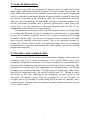
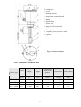
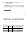
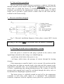
HEATER type EJK
with insulated heating elements
for water heaters
3 ~ 400 V
EJK- 3000
□
EJK- 4500
□
EJK- 6000
□
EJK- 9000
□
INSTALLATION AND USER MANUAL
WARRANTY CONDITIONS
Before installation please read carefully the following Installation and
User Manual as well as the Warranty Conditions.
Table of Contents:
1. General information ………………………………………………… 3
2. Structure and technical data ………………………………………... 3
3. Heater installation ………………………………………………........ 5
3.1 Assembly in tank ………………………………………........…....... 5
3.2 Electrical connections …………………………............................… 6
4. Turning on and water temperature setting ……………………......... 9
5. Overheating protection …………………………….....................…. 10
6. Anti-freeze protection …………………………….......................…. 10
7. Operating instructions ……………………………......…………….. 10
8. Warranty conditions ……………………………………………….... 13
ATTENTION!
1. Dry operation (without water) should be strictly avoided. Place the
plug in the socket only after the tank has been filled with water.
Otherwise heating elements may become overheated and damaged, and
therefore will require replacement.
2. The plug must be accessible after the heater is installed.
3. If the power cord is damaged, it should be replaced by the
manufacturer or by a specialized repair shop, or by a qualified person in
order to avoid risks.
The heater and the metal tank must be connected with a protective
conductor led from the marked terminal on the heater casing.
2
1. General information
Heaters type EJK are designed for heating water in open and closed
metal tanks, including enamelled domestic hot water tanks in particular. In
those tanks with anti-corrosion cathodic protection system using magnesium
anode or external current anode heating elements should be partially insulated
electrically from tank walls. Thanks to this, the electrochemical potential
difference between heating elements made of copper or special stainless steel
and the tank made of carbon steel is partially equalized in a tank filled with
water. This way the durability of heating elements and the life of the
magnesium anode are increased significantly.
The insulation of heating elements in EJK heaters is done by fixing them
in a casing wholly made of plastic, including the threaded part. A grounding
resistor of a suitable resistance is used for a partial connection of heating
elements with the tank. The resistor incorporates these elements in the tank
anti-corrosion cathodic protection system. This is an optimum solution to
protect the electric heater inside the enamelled tank from an accelerated
electrochemical corrosion, maintaining the tank cathodic protection and the
magnesium anode life.
2. Structure and technical data
Heaters type EJK are made of tubular heating elements with an internal
resistance wire and a casing containing a three phase 400V power unit,
including a temperature controller with stepless temperature adjustment and a
non-automatic temperature limiter to protect the heater from overheating. The
temperature controller knob and signal lamps are situated in the cover closing
the upper part of the casing body. The lower part of casing body ends with a
head with a hexagonal socket for an S-60 wrench and a 1½” thread to screw
the heater to the tank coupling. If the hexagonal wrench socket is not
accessible, the heater can be screwed in similarly to a car oil filter for
example, that is, by holding it by the casing which is made of a durable, heatresistant plastic. Heaters structure scheme and their technical data are shown
in fig. 1 and in table 1.
3
1 - casing body
2 - cover
3 - heating element
4 - temperature controller knob
5 - gland
6 - signal lamps
7 - power cord
8 - plug for STB connection
9 - grounding conductor
10 - capillary sensor protective tube
11 - gasket
Fig. 1. Heater structure
Tab. 1. Heaters technical data
Power
Supply
voltage
Dead zone
length
Immersion
depth to the
gasket
Threaded
connection
Minimum
tank volume
[kW]
[V]
[mm]
[mm]
[inch]
[dm³]
3.0
4.5
6.0
9.0
3 ~ 400
3 ~ 400
3 ~ 400
3 ~ 400
100
100
100
100
290
390
500
720
1 ½”
1 ½”
1 ½”
1 ½”
80
100
100
250
Heater type
EJK EJK EJK EJK -
3000
4500
6000
9000
4
3. Heater Installation
3.1 Assembly in tank
A. Type of tank
The tank and its connections must be made of metal. Both the tank and
all its other metal parts which are in contact with water must be connected
with the protective conductor in a permanent and reliable way.
B. Working position
During operation heating elements and the sensor protection must be
totally immersed in water and free thermally forced water circulation must be
ensured. The length of the coupling for assembling the heater shall not exceed
circa 100 mm so that it does not stand out from the heating elements dead
zone (unheated zone). The heater may only operate in horizontal or semi
horizontal position. Heater casing must not be covered nor thermally
insulated as it would disturb normal operation of the temperature controller
and of the temperature limiter installed in the casing. When assembling the
heater make sure that heating elements length fits into the tank and that they
do not touch any internal parts of the tank, such as heat exchangers or
thermometric pipes.
C. Pressure tanks
The heater is adapted for installation in pressure tanks of an admissible
pressure not higher than 10 bar. All the assembly, installation and service
conditions for these tanks (boilers) must be observed. It is also absolutely
obligatory to install a safety valve with the opening pressure not higher than
indicated in the tank operating parameters. Valve flow capacity should be
chosen taking into account the power of all heaters and heat exchangers
which heat water in tank, as regulated by the Office of Technical Inspection,
using the technical data published by particular safety valves manufacturers.
Safety valve opening pressure when heater type EJK is used must not
exceed 10 bar.
When installing an electric heater in a pressure tank it must be also
remembered that the operation of these devices is subject to various kinds of
technical inspection, particularly in accordance with the EU Pressure
Equipment Directive 97/23/EC. Among other things, it stipulates that:
1. Electric storage water heaters for domestic water of working
temperature not higher than 100ºC and capacity not larger than 300 l as well
as tanks filled with water (heat exchangers included) of working temperature
not higher than 100ºC and capacity not larger than 500 l are subject to
simplified inspection, and therefore do not need to be reported to the Office
of Technical Inspection.
5
2. Electric water heaters of capacity larger than 300 l as well as tanks
filled with water (heat exchangers included) of capacity larger than 500 l are
subject to limited inspection and need to be reported to the Office of
Technical Inspection.
D. Heater sealing
Seal the heater only with a flat gasket Ø 60 x Ø 48 mm (plane faying
surface on the heater head) or with an O-ring gasket Ø 46 mm x 5 mm
(grooved faying surface on heater head). As en exception, Teflon tape may
eventually be used. Make sure that the thread of the plastic head is not
damaged when the heater is screwed in.
3.2. Electrical connections
The heater should be connected by a properly qualified person
in co-ordination with the local electricity provider.
A. Heater power supply
Three phase current heaters with power of 3.0 kW, 4.5 kW, 6.0 kW and
9.0 kW are provided by the manufacturer with 1.5 m long, four-wire power
cords without plug. The free end of this cord should be connected to three
phase installation at the user's using a four pin plug and a proper socket or a
switch to ensure a proper disconnection on all poles for III category
overvoltage conditions. If it results necessary to lengthen the power cord, use
a cord with wire section not less than shown in table 2.
Tab. 2. Minimum wire section of power cord
Heater
type
EJK-3000
EJK-4500
EJK-6000
EJK-9000
Power
Rated current
Minimum
wire section
of power
cord
[kW]
[A]
[mm2 ]
3.0
4.5
6.0
9.0
4.3
6.5
8.7
13.0
1.0
1.0
1.5
1.5
6
Type of
gland in
heater
casing
Power cord
diameter
[mm]
PG 13.5
PG 13.5
PG 13.5
PG 13.5
6.0 ÷ 12.0
6.0 ÷ 12.0
6.0 ÷ 12.0
6.0 ÷ 12.0
B. Tank and heater grounding
The free end of the yellow and green protective conductor led from the
marked terminal on the heater casing must be obligatorily connected to the
metal tank in which the heater is assembled. If the yellow and green
conductor provided by the manufacturer results too short replace it with a
longer one to provide a good electric contact both on the tank and the
terminal on the heater casing.
C. Electrical installation diagram
1 - heating element
2 - temperature controller +
temperature limiter
3 - resistor
LS1 - green signal lamp
LS2 - red signal lamp
Fig. 2. Electrical installation diagram of three phase current 400V electric
heater
The plug or the switch must be accessible after the heater is installed.
4. Turning on and water temperature setting
After the power is turned on (the plug is placed in the socket), both
signal lamps situated on the casing cover should light up:
- green lamp, which shows that power is on,
- red lamp, which shows the passage of current through the heating
element.
If the temperature controller knob is in its extreme left position and the
red lamp does not light up, turn the knob to the right until the contacts in the
temperature controller close. It is recommended to supervise the first heating
of water, remembering that during heating process the volume of water in
pressure tank expands and it must be evacuated through the safety valve or
accumulated in a diaphragm expansion vessel.
The heater power is cyclically turned on and off by the temperature
controller as hot water cools down or is consumed. The temperature
controller cooperates with the capillary sensor placed in a special protective
7
pipe, immersed in water. By turning the temperature controller knob (tab. 4)
the desired temperature in water tank can be set steplessly up to +70 0C
maximum (turn the knob all the way to the right). When the set temperature is
achieved, temperature controller shall automatically turn off the power supply
to heating elements and shall turn it on again when water temperature drops
below the set temperature.
5. Overheating protection
The heater is protected against overheating by a non-automatic
temperature limiter, the so-called STB, which cuts off the current flow to the
heating unit in case of failure of the temperature controller and a temperature
rise over 900C. Power can be turned on again only after the heater cools down
and the button situated on the temperature limiter body is pressed. To do so,
remove the hole plug 8 (fig. 1) situated in the heater casing cover, and then
press the button using a small screwdriver for example (unplug the device
first). This operation shall be carried out only by a properly qualified person,
who will define the cause of the failure and remove it.
6. Anti-freeze protection
The temperature controller used in the heater is provided with an antifreeze protection feature to maintain the temperature of water in tank in the
level of +50C. This feature can be turned on by turning the temperature
controller knob all the way to the left. The heater is not turned off in this
position, it is anti-freeze protection only.
7. Operating instructions
A. Heaters type EJK do not need to be supervised during operation.
However, if the water is hard, heating elements should be periodically
cleaned of boiler scale as it blocks the heat flow and therefore
increases the current consumption and may cause damages of heating
elements.
B. The temperature of water in tank is set by the temperature controller
knob. Remember that electric energy consumption and accumulation
of boiler scale increase at higher temperatures. Temperatures of water
achieved for various settings during tests at the manufacturer's are
shown in tab. 3.
8
Tab. 3
Water temperature for various settings of temperature control knob
Three phase heater
(3 ~ 400 V)
Description
In its extreme left position the temperature
controller operates as an anti-freeze protection
feature, that is, it turns the heater on only after the
temperature drops down to +5oC.
Ca.+30oC, lukewarm water, directly suitable for
washing in a washbasin, no accumulation of
boiler scale
Ca.+50oC, moderately hot water, slight
accumulation of boiler scale
Ca.+70oC, hot water, high accumulation of boiler
scale
.
9
8. Warranty Conditions
1. Warranty is granted for a period of 24 months.
2. Warranty period starts on the day of sale of the product to the user, which
is inscribed in the warranty card and confirmed by a proof of purchase
(invoice) issued by the seller.
3. The warrantor ensures a proper functioning of the heater under the
condition that it is installed and used as described in the present manual.
4. Heating elements damaged due to excessive accumulation of boiler scale
are not covered by the warranty.
5. During the warranty period the user is entitled to have the heater repaired
free of charge in case of failures being the result of the manufacturer's
fault. These damages shall be eliminated within 14 days after they have
been reported.
6. Defects resulting from improper use, repairs and modifications carried out
by unauthorised persons and assembly and operation of the device contrary
to the present manual are not covered by the warranty.
7. In case of faulty operation of the heater please contact the manufacturer's
service calling at the telephone number +48 77 471 08 17 from 7:00 am. to
3:00 pm. or by e-mail: [email protected] or contact the store
where the product was purchased.
8. The method of repair shall be defined by the manufacturer.
9. The Warranty Card, filled in, complete and free of any modifications shall
be the ground for carrying out repairs by virtue of granted warranty.
10. To all matters not settled by the conditions above, the provisions of the
Civil Code shall apply.
11. It is recommended to keep the warranty card during the whole period of
use of the heater.
Waste electrical and electronic equipment (WEEE)
This product must not be treated as domestic waste.
The proper disposal helps to protect the environment. In order to
obtain more detailed information on the recycling of this product
please contact your disposal service provider or the store where
the product was purchased.
10