1
Cat. No. V106-E1-08
NB-series
NB3Q-TWB
NB5Q-TWB
NB7W-TWB
NB10W-TW01B
Programmable Terminals
© OMRON, 2011
All rights reserved. No part of this publication may be reproduced, stored in a retrieval system, or transmitted, in any form, or
by any means, mechanical, electronic, photocopying, recording, or otherwise, without the prior written permission of
OMRON.
No patent liability is assumed with respect to the use of the information contained herein. Moreover, because OMRON is
constantly striving to improve its high-quality products, the information contained in this manual is subject to change without
notice. Every precaution has been taken in the preparation of this manual. Nevertheless, OMRON assumes no responsibility
for errors or omissions. Neither is any liability assumed for damages resulting from the use of the information contained in
this publication.
Trademarks
• Sysmac and SYSMAC are trademarks or registered trademarks of OMRON Corporation in Japan and other
countries for OMRON factory automation products.
• Windows, Windows 98, Windows XP, Windows Vista, Windows 7, and Excel are registered trademarks of
Microsoft Corporation in the USA and other countries.
• EtherCAT® is registered trademark and patented technology, licensed by Beckhoff Automation GmbH, Germany.
• ODVA, CIP, CompoNet, DeviceNet, and EtherNet/IP are trademarks of ODVA.
• The SD logo is a trademark of SD-3C, LLC.
Other company names and product names in this document are the trademarks or registered trademarks of their
respective companies.
NB-series
NB3Q-TW
B
NB5Q-TW
B
NB7W-TW
B
NB10W-TW01B
Programmable Terminals
NB-Designer Operation Manual
Revised April 2013
Introduction
Thank you for purchasing an NB-series Programmable Terminal.
NB-Series Programmable Terminals (PTs) are designed to handle information generated in FA production
sites. Be sure to understand the functions and performances etc thoroughly before using PT correctly.
Intended Audience
This manual is intended for the following personnel, who must also have knowledge of electrical
systems (an electrical engineer or the equivalent).
• Personnel in charge of introducing FA systems into production facilities.
• Personnel in charge of designing FA systems.
• Personnel in charge of installing and connecting FA facilities.
• Personnel in charge of managing FA systems and facilities
General Precautions
• The user must operate the product according to the performance specifications described in the
operation manuals.
• Do not use the PT touch switch input functions for applications where danger to human life or serious
property damage is possible, or for emergency switch applications.
• Before using the product under conditions which are not described in the manual or applying the
product to nuclear control systems, railroad systems, aviation systems, vehicles, combustion
systems, medical equipment, amusement machines, safety equipment, and other systems,
machines and equipment that may have a serious influence on lives and property if used improperly,
consult your OMRON representative.
• Make sure that the ratings and performance characteristics of the product are sufficient for the
systems, machines, and equipment, and be sure to provide the systems, machines, and equipment
with double safety mechanisms.
• This manual provides information for connecting and setting up an NB-Series PT. Be sure to read
this manual before attempting to use the PT and keep this manual close at hand for reference during
installation and operation.
NB-series Programmable Terminals NB-Designer Operation Manual(V106)
1
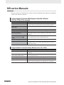
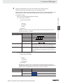
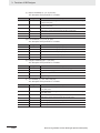
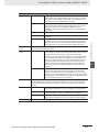
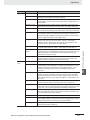
NB-series Manuals
NB-series manuals are organized in the sections listed in the following tables. Refer to the appropriate
section in the manuals as required.
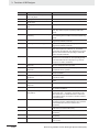
Programmable Terminals NB-Designer Operation Manual
(Cat. No. V106) (This manual)
Section
Contents
Section 1 Introduction
This section provides an outline of the NB-series PTs, including their
functions, features, connection types and communication methods.
Section 2 Installation and Startup of
NB-Designer
This section describes how to install and start the NB-Designer.
Section 3 Functions of NB-Designer
This section describes the functions of NB-Designer.
Section 4 Functions of NBManager
This section describes the functions of NBManager.
Section 5 Maintenance and
Abnormality Handling
This section describes the maintenance and check to prevent the
abnormality occurrence and the handling of the abnormalities occurred
in NB Unit.
Section 6 Descriptions of New
Functions Added into NBTW01B
This section describes the new functions added into NB-TW01B,
the system Properties and the component Properties.
Section 7 PictBridge Function
This section describes the PictBridge printing function.
Appendices
The appendices provide lists of the NB Units, the Communication Units,
the applicable PLCs, the memories sapported by PLC, and the list of
NB-Designer functions.
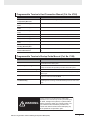
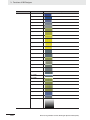
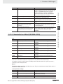
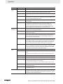
Programmable Terminals Setup Manual (Cat. No. V107)
Section
Contents
Section 1 Part Names and Functions This section describes the names and functions of the various parts of
an NB Unit.
2
Section 2 Installing the NB Unit and
Connecting Peripheral Devices
This section describes the methods used to install the NB Unit and
connect peripheral devices.
Section 3 System Setting Mode
This section describes the System Setting Mode.
Section 4 Calibrate Mode
This section describes the Calibrate Mode.
Appendices
The appendices provide information on specifications, dimensions,
wirings, and lists of the NB Units, the applicable PLCs and options.
NB-series Programmable Terminals NB-Designer Operation Manual(V106)
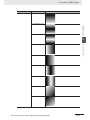
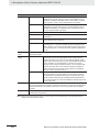
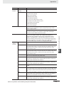
Programmable Terminals Host Connection Manual (Cat. No. V108)
Section
Contents
Section 1 List for All PLCs
Supported by NB series
This section lists all PLCs supported by NB Units.
Section 2 Connecting to SIEMENS
PLCs
This section describes the connection to SIEMENS PLCs.
Section 3 Connecting to Mitsubishi
PLCs
This section describes the connection to Mitsubishi PLCs.
Section 4 Connecting to Schneider
PLCs
This section describes the connection to Schneider PLCs.
Section 5 Modbus Connection
This section describes the connection on Modbus protocol.
Section 6 Connecting to Delta PLCs
This section describes the connection to Delta PLCs.
Section 7 Connecting to LG PLCs
This section describes the connection to LG PLCs.
Section 8 Connecting to Panasonic
PLCs
This section describes the connection to Panasonic PLCs.
Section 9 Connecting to AllenBradley (Rockwell) PLC
This section describes the connection to Allen-Bradley PLC.
Section 10 Connecting to PLC of GE
Fanuc Automation Inc.
This section describes the connection to PLC of GE Fanuc Automation
Inc.
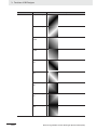
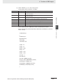
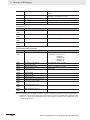
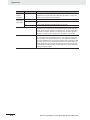
Programmable Terminals Startup Guide Manual (Cat. No. V109)
Section
Contents
Section 1 NB Overview
This section provide specifications of the NB Unit, describes its names
and functions of the various parts.
Section 2 System Design
This section describes the manual structure, takes NB7W as an
example to introduce the operation procedures of the NB system.
Section 3 Installation and Wiring
This section describes how to install and wire the NB Unit.
Section 4 Screen Creation
This section describes how to create a demonstration project through
NB-Designer.
Section 5 Run
This section describes how to start running at the Host side and
prepare to send screen data to NB7W.
Section 6 Maintenance and
Troubleshooting
This section describes the maintenance and inspection methods for
preventing errors occurring, and troubleshooting measures when errors
occur.
WARNING
Failure to read and understand the information
provided in this manual may result in personal injury
or death, damage to the product, or product failure.
Please read each section in its entirety and be sure
you understand the information provided in the
section and related sections before attempting any
of the procedures or operations given.
NB-series Programmable Terminals NB-Designer Operation Manual(V106)
3
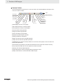
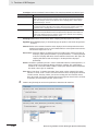
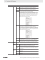
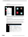
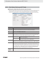
Manual Structure
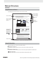
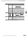
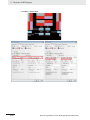
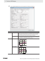
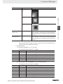
Page Structure and Icons
The following page structure and icons are used in this manual.
Level 1 heading
Level 2 heading
Level 3 heading
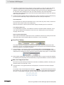
2 Installing the NB Unit and Connecting Peripheral Devices
Level 3 heading
2-1-2
Installation onto the Operation Panel
Use the metal kit and tool (a crosshead screwdriver) supplied with the Unit for installation.
Proceed the installation following the procedures below.
1
Step in a procedure
Indicates a step in a
procedure.
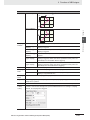
Panel cutout with dimensions is shown below. Fit the NB Unit into the panel from the front side.
Width
2-1 Installing the NB Unit
Install the NB Unit by embedding it into the operation panel.
2
Height
Models
2
Opening Dimension (W H mm)
NB3Q-TW00B/TW01B
119.0(+0.5/-0) 93.0(+0.5/-0)
NB5Q-TW00B/TW01B
172.4(+0.5/-0) 131.0(+0.5/-0)
NB7W-TW00B/TW01B
191.0(+0.5/-0) 137.0(+0.5/-0)
NB10W-TW01B
258.0(+0.5/-0) 200.0(+0.5/-0)
As follows, insert panel fixators at the locations indicated by red box around the back of the NB Unit.
Insert the hooks of positioners into the square holes on the Unit to hold the fixators properly, and
tighten the screws firmly with the screwdriver.
2-1-2 Installation onto the Operation Panel
Opening dimensions
Gives the current
headings.
Page tab
Gives the number
of the section.
NB5Q/NB7W-TWB
Special Information
(See below.)
Icons are used to indicate
precautions and
additional information.
Precautions for Safe Use
• When operating on the operation panel, make sure to keep metal particles from entering the
Unit.
The mounting panel must be between 1.6 and 4.8 mm thick. The NB Unit must be installed
in a control panel.
For the sake of waterproof and dustproof, all the fixators must be evenly tightened to a
torque of 0.5~0.6 Nm. If the tightening torque exceeds the specified value, or the tightening
is not even, deformation of the front panel may occur.
Make sure that the operation panel is clean, unbent, and strong enough for the installation
process.
Manual name
NB-series Programmable Terminals Setup Manual(V107)
2-3
This illustration is provided only as a sample and may not literally appear in this manual.
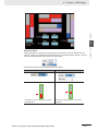
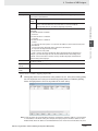
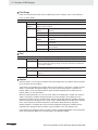
Special Information
Special information in this manual is classified as follows:
Precautions for Safe Use
Precautions on what to do and what not to do to ensure using the product safely.
Precautions for Correct Use
Precautions on what to do and what not to do to ensure proper operation and performance.
Additional Information
Additional information to increase understanding or make operation easier.
4
NB-series Programmable Terminals NB-Designer Operation Manual(V106)
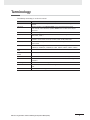
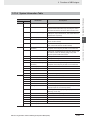
Terminology
The following terminology is used in this manual.
Terms
Descriptions
NB Unit
Indicates the main Unit of the products in the OMRON NB Series of Programmable
Terminal.
NB Series
Indicates products in the OMRON NB Series of Programmable Terminal.
In this manual, unless otherwise specified, NB Series is taken as the subject
concerned.
PLC
Indicates a Programmable Controller.
CP Series
Indicates the following products in the OMRON CP Series of Programmable Controllers:
CP1H, CP1L, CP1E
CS/CJ Series
Indicates the following products in the OMRON CS/CJ Series of Programmable
Controllers: CS1G, CS1H, CS1G-H, CS1H-H, CJ1G, CJ1M, CJ2M, CJ2H
NJ Series
Indicates the following OMRON SYSMAC NJ Series of Programmable Controllers:
NJ501, NJ301
C Series
Indicates the following products in the OMRON C Series of Programmable Controllers:
C200HX(-Z), C200HG(-Z), C200HE(-Z), CQM1, CQM1H, CPM1A, CPM2A, CPM2C
Serial Communication
Unit
Indicates a Serial Communication Unit for an OMRON SYSMAC CS/CJ-Series PLC.
Serial Communication
Board
Indicates a Serial Communication Board for an OMRON SYSMAC CS/CJ-Series PLC.
Communication Board
Indicates a Communication Board for an OMRON C200HX/HG/HE(-Z) PLC.
CPU Unit
Indicates a CPU Unit in the OMRON CP, CS/CJ or SYSMAC C Series of Programmable
Controllers.
NB-Designer
Indicates the OMRON NB-Designer.
Host
Indicates the PLC and other units functioning as the control devices for NB-Series
Units.
PT
Indicates an OMRON Programmable Terminal.
NB-series Programmable Terminals NB-Designer Operation Manual(V106)
5
6
NB-series Programmable Terminals NB-Designer Operation Manual(V106)
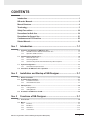
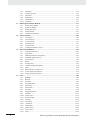
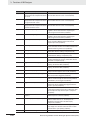
CONTENTS
Introduction............................................................................................................... 1
NB-series Manuals.................................................................................................... 2
Manual Structure ...................................................................................................... 4
Terminology .............................................................................................................. 5
Safety Precautions ................................................................................................. 16
Precautions for Safe Use ....................................................................................... 19
Precautions for Correct Use .................................................................................. 21
Conformance to EC Directives .............................................................................. 22
Related Manuals ..................................................................................................... 23
Sec. 1
Introduction ............................................................................ 1-1
1-1
1-2
1-3
Functions and Structure of NB-Series PTs ........................................................................... 1-2
1-1-1
How NB-Series PTs Work at FA Production Sites ...................................................................... 1-2
1-1-2
Operations of NB-Series PTs ..................................................................................................... 1-2
Communicating with the Host ................................................................................................ 1-4
1-2-1
What’s the Host Link? ................................................................................................................. 1-4
1-2-2
Connecting Methods................................................................................................................... 1-5
1-2-3
Communicating with the PLC Manufactured by Other Companies............................................. 1-6
System Configuration ............................................................................................................. 1-7
1-3-1
1-4
Sec. 2
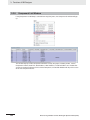
Connectable Peripheral Devices................................................................................................. 1-7
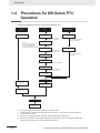
Procedures for NB-Series PTs’ Operation ............................................................................ 1-8
Installation and Startup of NB-Designer.............................. 2-1
2-1
Before Installation ................................................................................................................... 2-2
2-2
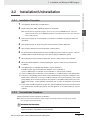
Installation/Uninstallation....................................................................................................... 2-3
2-3
2-4
Sec. 3
2-2-1
Installation Procedure ................................................................................................................. 2-3
2-2-2
Uninstallation Procedure............................................................................................................. 2-3
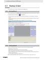
Startup & Quit .......................................................................................................................... 2-4
2-3-1
Starting Method .......................................................................................................................... 2-4
2-3-2
Quitting Method .......................................................................................................................... 2-4
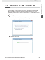
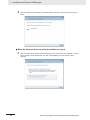
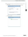
Installation of USB Driver for NB ........................................................................................... 2-5
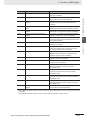
Functions of NB-Designer..................................................... 3-1
3-1
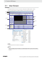
User Screen.............................................................................................................................. 3-4
3-2
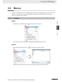
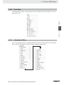
Menus ....................................................................................................................................... 3-7
3-2-1
File Menu .................................................................................................................................... 3-7
3-2-2
Edit Menu.................................................................................................................................. 3-10
3-2-3
View Menu ................................................................................................................................ 3-15
3-2-4
Screen Menu ............................................................................................................................ 3-26
NB-series Programmable Terminals NB-Designer Operation Manual(V106)
7
3-3
3-4
3-5
3-6
8
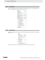
3-2-5
Draw Menu................................................................................................................................ 3-29
3-2-6
Components Menu.................................................................................................................... 3-29
3-2-7
Tools Menu................................................................................................................................ 3-30
3-2-8
Option Menu.............................................................................................................................. 3-30
3-2-9
Window Menu ........................................................................................................................... 3-31
3-2-10
Help Menu................................................................................................................................. 3-32
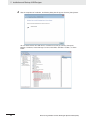
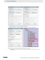
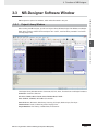
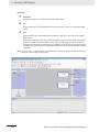
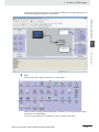
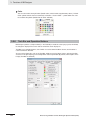
NB-Designer Software Window ............................................................................................ 3-33
3-3-1
Project Library Window ............................................................................................................. 3-33
3-3-2
Project File Window .................................................................................................................. 3-37
3-3-3
Project Work Space .................................................................................................................. 3-37
3-3-4
Output Window.......................................................................................................................... 3-43
3-3-5
Component List Window ........................................................................................................... 3-44
Screen Concept ..................................................................................................................... 3-45
3-4-1
Screen Types ............................................................................................................................ 3-45
3-4-2
Screen Property ........................................................................................................................ 3-48
3-4-3
Screen Creation ........................................................................................................................ 3-52
3-4-4
Screen Opening ........................................................................................................................ 3-52
3-4-5
Screen Deletion......................................................................................................................... 3-53
3-4-6
Components Related to Screen ................................................................................................ 3-53
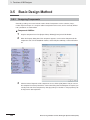
Basic Design Method ............................................................................................................ 3-54
3-5-1
Designing Components............................................................................................................. 3-54
3-5-2
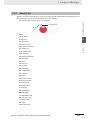
About ID No............................................................................................................................... 3-55
3-5-3
Additional Comments (Descriptions)......................................................................................... 3-56
3-5-4
Read/Write Address for PLC..................................................................................................... 3-57
3-5-5
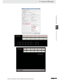
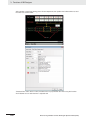
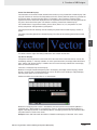
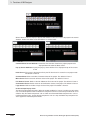
Vector Graphic .......................................................................................................................... 3-58
3-5-6
Bitmap ....................................................................................................................................... 3-63
3-5-7
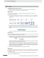
Creating Label........................................................................................................................... 3-66
3-5-8
Task Bar and Operation Buttons ............................................................................................... 3-68
3-5-9
Fonts ......................................................................................................................................... 3-70
3-5-10
Basic Properties of Component ................................................................................................ 3-73
3-5-11
Control Setting of Component................................................................................................... 3-74
3-5-12
Display Setting of Component................................................................................................... 3-78
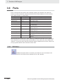
Parts........................................................................................................................................ 3-80
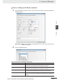
3-6-1
Bit Button................................................................................................................................... 3-80
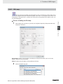
3-6-2
Bit Lamp .................................................................................................................................... 3-83
3-6-3
Bit Switch .................................................................................................................................. 3-86
3-6-4
Command Button ...................................................................................................................... 3-87
3-6-5
Word Lamp................................................................................................................................ 3-92
3-6-6
Word Switch .............................................................................................................................. 3-94
3-6-7
XY Graph .................................................................................................................................. 3-98
3-6-8
Moving Component ................................................................................................................. 3-107
3-6-9
Animation ................................................................................................................................ 3-112
3-6-10
Number Input .......................................................................................................................... 3-114
3-6-11
Number Display....................................................................................................................... 3-120
3-6-12
Text Input................................................................................................................................. 3-123
3-6-13
Text Display ............................................................................................................................. 3-127
3-6-14
Level Meter.............................................................................................................................. 3-128
3-6-15
Analog Meter........................................................................................................................... 3-139
3-6-16
Indirect Screen ........................................................................................................................ 3-143
3-6-17
Direct Screen .......................................................................................................................... 3-146
3-6-18
Alarm....................................................................................................................................... 3-148
NB-series Programmable Terminals NB-Designer Operation Manual(V106)
3-6-19
3-7
3-8
3-9
Data Log ................................................................................................................................. 3-150
3-6-20
Recipe..................................................................................................................................... 3-160
3-6-21
Oscillograph............................................................................................................................ 3-160
3-6-22
Scroll Bar ................................................................................................................................ 3-164
3-6-23
Event....................................................................................................................................... 3-167
3-6-24
Note Book ............................................................................................................................... 3-174
3-6-25
Word Neon Lamp.................................................................................................................... 3-185
3-6-26
Bit Neon Lamp ........................................................................................................................ 3-186
3-6-27
Touch Trigger .......................................................................................................................... 3-187
3-6-28
Table ....................................................................................................................................... 3-189
3-6-29
Data History............................................................................................................................ 3-190
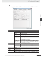
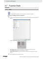
Function Parts ..................................................................................................................... 3-196
3-7-1
Scale....................................................................................................................................... 3-196
3-7-2
Function Key ........................................................................................................................... 3-197
3-7-3
Alarm Display.......................................................................................................................... 3-205
3-7-4
Timer....................................................................................................................................... 3-209
3-7-5
Bitmap..................................................................................................................................... 3-214
3-7-6
Vector Graphic ........................................................................................................................ 3-215
3-7-7
Notepad .................................................................................................................................. 3-216
3-7-8
Data Transmission .................................................................................................................. 3-219
3-7-9
Freeplotting ............................................................................................................................. 3-222
3-7-10
Date/Time ............................................................................................................................... 3-223
3-7-11
Indirect Shape......................................................................................................................... 3-225
3-7-12
User Information ..................................................................................................................... 3-229
3-7-13
Multifunction............................................................................................................................ 3-229
3-7-14
Event Display .......................................................................................................................... 3-232
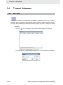
Project Database ................................................................................................................. 3-234
3-8-1
Text Library ............................................................................................................................. 3-234
3-8-2
Variable Table ......................................................................................................................... 3-240
3-8-3
Alarm Setting .......................................................................................................................... 3-243
3-8-4
Event Setting .......................................................................................................................... 3-248
3-8-5
PLC Control ............................................................................................................................ 3-252
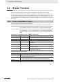
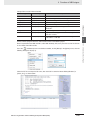
Macro Function .................................................................................................................... 3-260
3-9-1
Create a Simple Macro Program ............................................................................................ 3-260
3-9-2
Macro and Specification of Operation with Read/Write Variables .......................................... 3-267
3-9-3
Macro Triggering..................................................................................................................... 3-268
3-9-4
Other Descriptions.................................................................................................................. 3-270
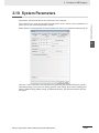
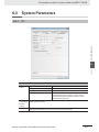
3-10 System Parameters ............................................................................................................. 3-283
3-10-1
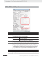
PT ........................................................................................................................................... 3-284
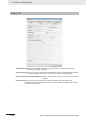
3-10-2
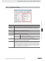
Task Bar.................................................................................................................................. 3-285
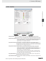
3-10-3
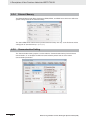
PT Extended Properties ......................................................................................................... 3-287
3-10-4
System Information Setting..................................................................................................... 3-296
3-10-5
Security Levels Setting ........................................................................................................... 3-298
3-10-6
User Permission Setting ......................................................................................................... 3-300
3-10-7
Event History Setting .............................................................................................................. 3-314
3-10-8
COM1/COM2 Setting.............................................................................................................. 3-315
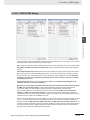
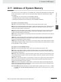
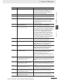
3-11 Address of System Memory ............................................................................................... 3-317
3-11-1
Local Bit (LB) .......................................................................................................................... 3-318
3-11-2
Local Word (LW) ..................................................................................................................... 3-322
3-11-3
Nonvolatile Local Word (LW10000~10255) ............................................................................ 3-325
3-11-4
System Information Table ....................................................................................................... 3-327
NB-series Programmable Terminals NB-Designer Operation Manual(V106)
9
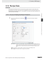
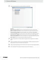
3-12 Recipe Data .......................................................................................................................... 3-329
3-12-1
Process of Creating One Recipe Data Transmission Component .......................................... 3-329
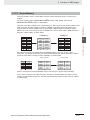
3-12-2
Recipe Memory....................................................................................................................... 3-331
3-12-3
Upload/Download of Recipe Data between PT and PLC........................................................ 3-335
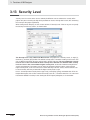
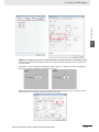
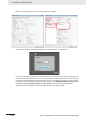
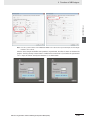
3-13 Security Level ...................................................................................................................... 3-340
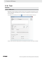
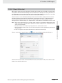
3-14 Test ....................................................................................................................................... 3-346
3-14-1
Offline test ............................................................................................................................... 3-346
3-14-2
Direct Online test..................................................................................................................... 3-347
3-14-3
Indirect Online test .................................................................................................................. 3-348
3-15 Download.............................................................................................................................. 3-349
3-15-1
Transmission Setting ............................................................................................................... 3-349
3-15-2
Download via USB Memory .................................................................................................... 3-351
3-15-3
Specification of Downloading Contents................................................................................... 3-351
3-16 Other Functions ................................................................................................................... 3-355
3-17 RecipeEditor ........................................................................................................................ 3-397
Sec. 4
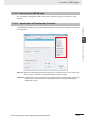
Functions of NBManager ...................................................... 4-1
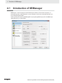
4-1
Introduction of NBManager .................................................................................................... 4-2
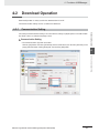
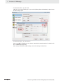
4-2
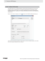
Download Operation................................................................................................................ 4-3
Communication Setting ............................................................................................................... 4-3
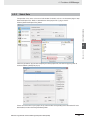
4-2-2
Select Data.................................................................................................................................. 4-5
4-2-3
LOGO Setting.............................................................................................................................. 4-8
4-2-4
Clear Data ................................................................................................................................... 4-9
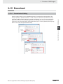
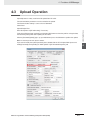
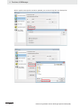
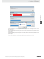
4-3
Upload Operation .................................................................................................................. 4-11
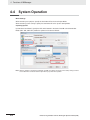
4-4
System Operation .................................................................................................................. 4-14
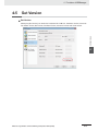
4-5
Get Version............................................................................................................................. 4-15
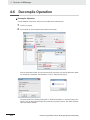
4-6
Decompile Operation ............................................................................................................ 4-16
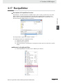
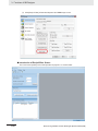
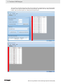
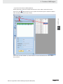
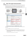
4-7
Pass Through Communication............................................................................................. 4-17
Sec. 5
Maintenance and Abnormality Handling ............................. 5-1
5-1
Maintenance ............................................................................................................................. 5-2
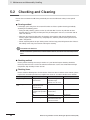
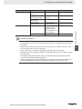
5-2
Checking and Cleaning ........................................................................................................... 5-4
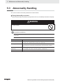
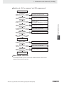
5-3
Abnormality Handling ............................................................................................................. 5-6
5-4
Unit Replacement Precautions............................................................................................... 5-9
Sec. 6
Descriptions of New Functions Added into NB
-TW01B...........6-1
6-1
10
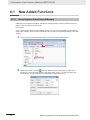
4-2-1
New Added Functions ............................................................................................................. 6-2
6-1-1
Using Graphics From External Memory ...................................................................................... 6-2
6-1-2
System Reserved memory.......................................................................................................... 6-3
6-1-3
Recipe ......................................................................................................................................... 6-3
6-1-4
Download through Ethernet ........................................................................................................ 6-4
6-1-5
Download to USB1...................................................................................................................... 6-5
6-1-6
NBManager ................................................................................................................................. 6-6
6-1-7
Data Encryption .......................................................................................................................... 6-7
6-1-8
New Added Addresses for System memories............................................................................. 6-9
6-1-9
Change of System Language.................................................................................................... 6-10
NB-series Programmable Terminals NB-Designer Operation Manual(V106)
6-1-10
6-2
6-3
Sec. 7
Usage of Forced Address Bit.................................................................................................... 6-10
System Parameters ............................................................................................................... 6-11
6-2-1
PT ............................................................................................................................................. 6-11
6-2-2
PT Extended Properties ........................................................................................................... 6-12
6-2-3
Event History Setting ................................................................................................................ 6-13
6-2-4
External Memory ...................................................................................................................... 6-14
6-2-5
Communication Setting............................................................................................................. 6-14
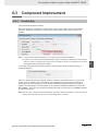
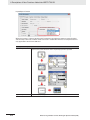
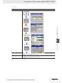
Component Improvement ..................................................................................................... 6-15
6-3-1
Function Key ............................................................................................................................. 6-15
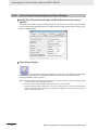
6-3-2
Event, Event History Display and Event Display....................................................................... 6-18
6-3-3
Data History, Data Log and XY Graph...................................................................................... 6-20
6-3-4
Operation Log ........................................................................................................................... 6-21
6-3-5
Recipe Data .............................................................................................................................. 6-24
6-3-6
PLC Control .............................................................................................................................. 6-25
6-3-7
File List ..................................................................................................................................... 6-26
PictBridge Printing ................................................................ 7-1
7-1
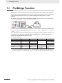
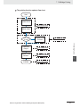
PictBridge Function ................................................................................................................ 7-2
7-2
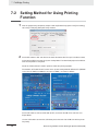
Setting Method for Using Printing Function ......................................................................... 7-4
7-3
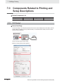
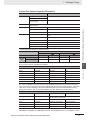
Components Related to Printing and Setup Descriptions .................................................. 7-6
7-3-1
PLC Control ................................................................................................................................ 7-6
7-4
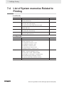
List of System memories Related to Printing ....................................................................... 7-8
7-5
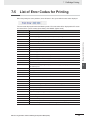
List of Error Codes for Printing.............................................................................................. 7-9
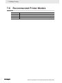
7-6
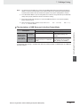
Recommended Printer Models ............................................................................................. 7-10
Sec. A
Appendices.............................................................................A-1
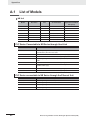
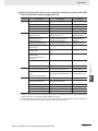
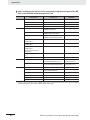
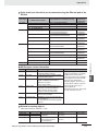
A-1 List of Models ..........................................................................................................................A-2
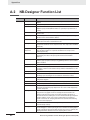
A-2 NB-Designer Function List .....................................................................................................A-6
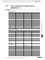
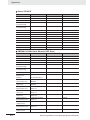
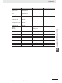
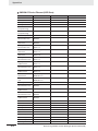
A-3 List of memories supported by OMRON PLC .....................................................................A-11
Revision History ....................................................................................................... 1
NB-series Programmable Terminals NB-Designer Operation Manual(V106)
11
12
NB-series Programmable Terminals NB-Designer Operation Manual(V106)
Read and Understand this Manual
Please read and understand this manual before using the product. Please consult your OMRON representative
if you have any questions or comments.
Warranty and Limitations of Liability
WARRANTY
OMRON’s exclusive warranty is that the products are free from defects in materials and workmanship for a
period of one year (or other period if specified) from date of sale by OMRON.
OMRON MAKES NO WARRANTY OR REPRESENTATION, EXPRESS OR IMPLIED, REGARDING NONINFRINGEMENT, MERCHANTABILITY, OR FITNESS FOR PARTICULAR PURPOSE OF THE
PRODUCTS. ANY BUYER OR USER ACKNOWLEDGES THAT THE BUYER OR USER ALONE HAS
DETERMINED THAT THE PRODUCTS WILL SUITABLY MEET THE REQUIREMENTS OF THEIR
INTENDED USE. OMRON DISCLAIMS ALL OTHER WARRANTIES, EXPRESS OR IMPLIED.
LIMITATIONS OF LIABILITY
OMRON SHALL NOT BE RESPONSIBLE FOR SPECIAL, INDIRECT, OR CONSEQUENTIAL DAMAGES,
LOSS OF PROFITS OR COMMERCIAL LOSS IN ANY WAY CONNECTED WITH THE PRODUCTS,
WHETHER SUCH CLAIM IS BASED ON CONTRACT, WARRANTY, NEGLIGENCE, OR STRICT
LIABILITY.
In no event shall the responsibility of OMRON for any act exceed the individual price of the product on which
liability is asserted.
IN NO EVENT SHALL OMRON BE RESPONSIBLE FOR WARRANTY, REPAIR, OR OTHER CLAIMS
REGARDING THE PRODUCTS UNLESS OMRON’S ANALYSIS CONFIRMS THAT THE PRODUCTS
WERE PROPERLY HANDLED, STORED, INSTALLED, AND MAINTAINED AND NOT SUBJECT TO
CONTAMINATION, ABUSE, MISUSE, OR INAPPROPRIATE MODIFICATION OR REPAIR.
NB-series Programmable Terminals NB-Designer Operation Manual(V106)
13
Application Considerations
SUITABILITY FOR USE
OMRON shall not be responsible for conformity with any standards, codes, or regulations that apply to the
combination of products in the customer’s application or use of the products.
At the customer’s request, OMRON will provide applicable third party certification documents identifying
ratings and limitations of use that apply to the products. This information by itself is not sufficient for a
complete determination of the suitability of the products in combination with the end product, machine,
system, or other application or use.
The following are some examples of applications for which particular attention must be given. This is not
intended to be an exhaustive list of all possible uses of the products, nor is it intended to imply that the uses
listed may be suitable for the products:
• Outdoor use, uses involving potential chemical contamination or electrical interference, or conditions or
uses not described in this manual.
• Nuclear energy control systems, combustion systems, railroad systems, aviation systems, medical
equipment, amusement machines, vehicles, safety equipment, and installations subject to separate
industry or government regulations.
• Systems, machines, and equipment that could present a risk to life or property.
Please know and observe all prohibitions of use applicable to the products.
NEVER USE THE PRODUCTS FOR AN APPLICATION INVOLVING SERIOUS RISK TO LIFE OR
PROPERTY WITHOUT ENSURING THAT THE SYSTEM AS A WHOLE HAS BEEN DESIGNED TO
ADDRESS THE RISKS, AND THAT THE OMRON PRODUCTS ARE PROPERLY RATED AND INSTALLED
FOR THE INTENDED USE WITHIN THE OVERALL EQUIPMENT OR SYSTEM.
PROGRAMMABLE PRODUCTS
OMRON shall not be responsible for the user’s programming of a programmable product, or any
consequence thereof.
14
NB-series Programmable Terminals NB-Designer Operation Manual(V106)
Disclaimers
CHANGE IN SPECIFICATIONS
Product specifications and accessories may be changed at any time based on improvements and other
reasons.
It is our practice to change model numbers when published ratings or features are changed, or when
significant construction changes are made. However, some specifications of the products may be changed
without any notice. When in doubt, special model numbers may be assigned to fix or establish key
specifications for your application on your request. Please consult with your OMRON representative at any
time to confirm actual specifications of purchased products.
DIMENSIONS AND WEIGHTS
Dimensions and weights are nominal and are not to be used for manufacturing purposes, even when
tolerances are shown.
PERFORMANCE DATA
Performance data given in this manual is provided as a guide for the user in determining suitability and does
not constitute a warranty. It may represent the result of OMRON’s test conditions, and the users must
correlate it to actual application requirements. Actual performance is subject to the OMRON Warranty and
Limitations of Liability.
ERRORS AND OMISSIONS
The information in this manual has been carefully checked and is believed to be accurate; however, no
responsibility is assumed for clerical, typographical, or proofreading errors, or omissions.
NB-series Programmable Terminals NB-Designer Operation Manual(V106)
15
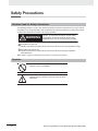
Safety Precautions
Notation Used for Safety Information
The following notation is used in this manual to provide precautions required to ensure safe usage of
the product. The safety precautions that are provided are extremely important to safety. Always read
and heed the information provided in all safety precautions.
WARNING
Indicates an imminently hazardous situation which,
if not avoided, will result in death or serious injury.
Additionally, there may be severe property damage.
Precautions for Safe Use
Indicates precautions on what to do and what not to do to ensure using the product safely.
Precautions for Correct Use
Indicates precautions on what to do and what not to do to ensure proper operation
and performance.
Note Indicates suggestive information and precautions on operation of the product.
Symbols
• Prohibition
Indicates a general prohibition.
• Caution
Indicates general cautionary, warning, or danger level
information.
16
NB-series Programmable Terminals NB-Designer Operation Manual(V106)
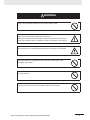
WARNING
Do not attempt to take the product apart and do not touch the product inside while the
power is being supplied. Otherwise it may result in electric shock.
Always ensure that the personnel in charge confirm that installation, inspection, and
maintenance were properly performed for the NB Unit.
“Personnel in charge” refers to individuals qualified and responsible for ensuring
safety during machine design, installation, operation, maintenance, and disposal.
Ensure that installation and post-installation checks are performed by personnel in
charge who possess a thorough understanding of the machinery to be installed.
Do not use the input functions of the touch switch, etc. of the NB Unit, in applications
that involve human life, in applications that may result in serious injury, or for
emergency stop switches.
Do not attempt to disassemble, repair, or modify the NB Unit. Otherwise it may impair
the safety functions.
Never press more than two points on the touch panel of the NB Unit at a time.
Otherwise, it may activate a switch somewhere between the two points.
NB-series Programmable Terminals NB-Designer Operation Manual(V106)
17
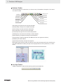
Precaution
WARNING
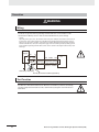
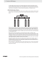
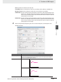
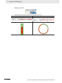
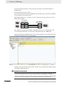
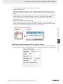
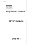
Wiring
In the case of the NB Series, when grounding the positive terminal of power supply of 24 V to
the NB, do not ground functional grounding terminal at NB side. Some functions of a PC
connected to the NB may cause a short circuit and the NB Unit may cause damage.
• Caution:
Depending on the types of PC, SG terminals of RS-232C port or USB port and contour of connector can
be connected. As the contour of tool port of the NB and the functional grounding terminal are not insulated, they are connected. Therefore, connecting the PC allows GND terminal and functional grounding
terminal of the NB to be connected. If the power supply of 24V to the NB is grounded positively, grounding the functional grounding terminal allows a short circuit as shown in the diagram below and may result
in damage.
Power
Supply
NB
24V
PC
0V
GND
SG
Cable
SG
Functional
Grounding
Contour Contour
Grounding Grounding
Do not ground the functional grounding.
Test Function
The Test Function is performed on PC so that a problem may occur affected by the timing or
the differences with communication route. When the test function is performed, considering
possible unexpected circumstances on PC, confirm that any dangerous event will not occur
beforehand.
18
NB-series Programmable Terminals NB-Designer Operation Manual(V106)
Precautions for Safe Use
• When unpacking the NB Units and the peripheral devices, check carefully for any external scratches
or other damages. Also, shake the Units gently and check for any abnormal sound.
• The NB Unit must be installed in a control panel.
• The mounting panel must be between 1.6 and 4.8 mm thick. Tighten the Mounting Brackets evenly to a
torque of between 0.5 and 0.6 Nxm to maintain water and dust resistance. If the tightening torque
exceeds the specified value, or the tightening is not even, deformation of the front panel may occur.
What is more, make sure the panel is not dirty or warped and that it is strong enough to hold the Units.
• Do not let metal particles enter the Units when preparing the panel.
• Do not connect an AC power supply to the DC power terminals.
• Use a DC power with a slight voltage fluctuation and reinforced or double insulation, and that will
provide a stable output even if the input is momentarily interrupted for 10 ms.
Rated Power Supply Voltage: DC 24 V (Allowable range DC 20.4 ~ 27.6 V)
• Do not perform a dielectric voltage test.
• Before connecting the power supply to the NB unit, mount the cable on the terminal block. Make the
connection by using terminal screws crimping on a twisted-pair cable with a crimping range of 12~26
AWG, and only 6.5 mm of insulation peel of the cable needs to be peeled off. Tighten the terminal
screws at a torque of between 0.3 and 0.5 Nxm. Make sure the screws are properly tightened. Do not
use the terminal block of NB3Q-TW01B for other models. NB3Q-TW01B has different pin definitions
on the terminal block.
• To prevent malfunctions caused by noise, ground the Unit correctly.
• Do not touch the packaging part of the circuit board with your bare hands. Discharge any static
electricity from your body before handling the board.
• When using the No. 6 pin of the serial communication port COM1 connector for a voltage of DC+5V,
make sure the supply equipment’s current capacity is below 250mA before using it. The DC+5V
voltage output of the NB unit is +5V±5%, and the maximum current is 250mA. (The serial
communication port COM1 of NB3Q-TW00B and NB3Q-TW01B is unable to output the current.)
• Turn OFF the power supply before connecting or disconnecting cables.
• Always keep the connector screws firmly tightened after the communication cable is connected.
• The maximum tensile load for cables is 30 N. Do not apply loads greater than this.
• Confirm the safety of the system before turning ON or OFF the power supply, or pressing the reset button.
• The whole system may stop depending on how the power supply is turned ON or OFF. Turn ON/OFF
the power supply according to the specified procedure.
• Reset by pressing the reset button, or restart the power supply, once the DIP switch settings are changed.
• To ensure the system’s safety, make sure to incorporate a program that can confirm the normal
functionality of the NB Unit before running the system.
• Start actual system application only after sufficiently checking screen data, macros and the operation
of the program at the host side.
• Do not press the touch panel with a force greater than 30 N.
• Do not use hard or pointed objects to operate or scrub the screen, otherwise the surface of the
screen may be damaged.
• Confirm the safety of the system before pressing the touch panel.
• Signals from the touch switches may not be input if the touch switches are pressed consecutively at
high speed. Confirm each input before proceeding to the next one.
• Do not accidentally press the touch panel when the backlight is not lit or when the display does not
appear. Make sure of the safety of the system before pressing the touch panel.
• To use numeric input functions safely, always make maximum and minimum limit settings.
• Before initializing screen data, confirm that existing data is backed up at the NB-Designer.
NB-series Programmable Terminals NB-Designer Operation Manual(V106)
19
• When changing the password with the screen, do not reset or turn OFF the power supply until writing
is finished. Failure to save the password may cause the screen to fail to function.
• When using an equipment monitor, confirm the safety of the system before carrying out the following operations:
• Changing monitor data.
• Changing operation mode.
• Forced set/reset.
• Changing the current value or the set value.
• Do not connect a USB connector to any device that is not applicable.
• When connecting the equipment with the USB HOST connector, make sure the supply equipment’s
current capacity is below 150mA before using it. The DC+5V voltage output of the NB Unit is
+5V±5%, and the maximum current is 150mA.
• Before connecting a USB connector to a device, make sure that the device is free of damage.
• Commercially available and the recommended USB HUBs are different from the general
specifications of the NB Unit. The unit may not function well in an environment subject to noise, static
electricity. Therefore, when using a USB HUB, employ sufficient noise and static electricity insulation
measures, or install it at a site free of noise or static electricity.
• While uploading or downloading screen data or system programs, do not perform the following
operations that may corrupt the screen data or the system program:
• Turning OFF the power supply of the NB Unit.
• Pressing the PT’s reset switch.
• Dispose of the Units and batteries according to local ordinances as they apply.
• Do not dispose the product into a fire. Doing so may cause the damage with the battery or electronic components.
• Do not apply an impact with the lithium cell, charge it, dispose it into a fire, or heat it. Doing either of
them may cause an ignition or a bursting.
• When exporting products with lithium primary batteries containing perchlorate at 6ppb or above to or
delivering them through California, USA, the following precautionary measures have to be publicized.
Perchlorate material - applicable through special processing. Refer to
http://www.dtsc.ca.gov/hazardouswaste/perchlorate.
NB-Series products contain lithium primary batteries. When exporting products containing this kind of
batteries to or delivering them through California, USA, label all the product packages as well as the
appropriate delivery packages.
• Do not use benzene, paint thinner, or other volatile solvents, and do not use chemically treated cloths.
• Do not dispose the Units together with general waste at waste yards. When disposing them, follow
the related local ordinances or rules.
• Cannot replace the backlight lamp inside the NB Unit.
• Deterioration over time can cause the touch points to move. Calibrate the touch panel periodically.
• Water and oil resistance will be lost if the front sheet is torn or is peeling off. Do not use the Unit, if the
front sheet is torn or is peeling off.
• The rubber packing will deteriorate, shrink, or harden depending on the operating environment.
Inspect the rubber packing periodically.
• The communication cables of the COM1 and COM2 connectors are not interchangeable. Confirm the pins
of the ports before carrying out communications. (NB3Q-TW00B and NB3Q-TW01B only has COM1.)
• Periodically check the installation conditions in applications where the PT is subject to contact with oil or water.
• Do not perform the following operations during the communication of the USB memory:
• Turning off the power supply of the NB Unit.
• Pressing the Reset button on the NB Unit.
• Removing the USB memory.
• Do not use the USB memory in the environment subject to strong vibration.
20
NB-series Programmable Terminals NB-Designer Operation Manual(V106)
Precautions for Correct Use
• Do not install the unit in any of the following locations:
Locations subject to severe changes in temperature
Locations subject to temperatures or humidity outside the range specified in the specifications
Locations subject to condensation as the result of high humidity
Locations subject to corrosive or flammable gases
Locations subject to strong shock or vibration
Locations outdoors subject to direct wind and rain
Locations subject to strong ultraviolet light
Locations subject to dust
Locations subject to direct sunlight
Locations subject to splashing oil or chemicals
• Take appropriate and sufficient countermeasures when installing systems in the following locations:
Locations subject to static electricity or other forms of noise
Locations subject to strong electric field or magnetic field
Locations close to power supply lines
Locations subject to possible exposure to radioactivity
• Precautions for software:
The update, restoration, uninstall and reinstallation of software in running status is prohibited in order
to guarantee the correct use of the product.
NB-series Programmable Terminals NB-Designer Operation Manual(V106)
21
Conformance to EC Directives
NB-Series Programmable Terminals are EMC compliant.
Concepts
OMRON products are electronic devices that are incorporated in machines and manufacturing
installations. OMRON PTs conform to the related EMC Directives (see note) so that the devices and
machines into which they are built can more easily conform to EMC Directives. The actual products
have been through inspections and are completely in accordance with EMC directives. However, when
they are built into customers’ systems, whether the systems also comply with these Directives is up to
the customers for further inspection.
EMC-related performance of OMRON PTs will vary depending on the configuration, wiring, and other
conditions of the OMRON equipment or control panel. The customer must, therefore, perform final
checks to confirm that the overall machine or device conforms to EMC standards.
Note The applicable EMC (Electromagnetic Compatibility) standards are as follows:
EMS (Electromagnetic sensitivity): EN61131-2: 2007
EMI (Electromagnetic Interference): EN61131-2: 2007
Conformance to EC Directives
NB-Series Programmable Terminals are EC compliant. Heed the following precautions in order to
ensure that the customer’s overall machine and device conform to EC Directives.
1
2
3
4
22
The PT must be installed in a control panel.
You must use reinforced insulation or double insulation for the DC power supply and the DC
power supply must have minimal voltage fluctuations and provide a stable output even if the
power supply input is interrupted for 10 ms.
The PTs conform to the standard EN 61131-2, but radiated emission characteristics (10m
regulations) may vary depending on the configuration of the control panel used, other devices
connected to the control panel, wiring, and other conditions. You must therefore confirm that the
overall machine or equipment complies with EC Directives.
This is a Class A product (Product for industry purpose). It may cause radio interference in
residential areas, in which case the user may be required to take adequate measures to reduce
interference.
NB-series Programmable Terminals NB-Designer Operation Manual(V106)
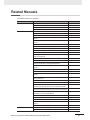
Related Manuals
The related manuals are as follows:
Devices and Software
NB series
PLC
Manual Name
Manual No.
NB Series NB-Designer Operation Manual (This manual)
V106
NB Series Setup Manual
V107
NB Series Host Connection Manual
V108
NB Series Startup Guide
V109
SYSMAC CP Series CP1L CPU Unit Operation Manual
W462
SYSMAC CP Series CP1H/L CPU Unit Programming Manual
W451
SYSMAC CP Series CP1H CPU Unit Operation Manual
W450
SYSMAC CP Series CP1E CPU Unit Hardware USER’S
Manual
W479
SYSMAC CP Series CP1E CPU Unit Software USER’S
Manual
W480
SYSMAC C200HX/HG/HE(-E/-ZE) Installation Guide
W302
SYSMAC C200HX/HG/HE Operation Manual
W303
SYSMAC C200HX/HG/HE(-ZE) Operation Manual
W322
SYSMAC CPM1A Operation Manual
W317
SYSMAC CPM2A Operation Manual
W352
SYSMAC CPM1/CPM1A/CPM2A/CPM2C/SRM1(-V2)
Programming Manual
W353
SYSMAC CPM2C Operation Manual
W356
SYSMAC CS1 Series CS1G/H Operation Manual
W339
SYSMAC CS/CJ Series Serial Communications Boards and
Serial Communications Units Operation Manual
W336
SYSMAC CJ Series CJ1G/H(-H) CJ1M CJ1G Operation
Manual
W393
SYSMAC CS/CJ Series Programming Manual
W394
SYSMAC CS/CJ Series INSTRUCTIONS Reference Manual
W340
SYSMAC CS/CJ Series Programming Consoles Operation
Manual
W341
SYSMAC CS/CJ Series Communications Commands
Reference Manual
W342
SYSMAC CJ Series CJ2 CPU Unit Hardware USER’S Manual W472
SYSMAC CJ Series CJ2 CPU Unit Software USER’S Manual
W473
SYSMAC CS/CJ Series CS1W/CJ1W-ETN21 (100Base-TX)
Ethernet Units Operation Manual Construction of Networks
W420
SYSMAC CS/CJ Series CS1W/CJ1W-ETN21 (100Base-TX)
Ethernet Units Operation Manual Construction of Applications
W421
SYSMAC CS/CJ Series CS1W/CJ1W-EIP21 (100Base-TX)
EtherNet/IPTM Units Operation Manual
W465
SYSMAC CP Series CP1L-EL/EM CPU Unit Operation Manual W516
NJ Series CPU Unit Hardware USER’S Manual
W500
NJ Series CPU Unit Software USER’S Manual
W501
NJ Series CPU Unit Built-in EtherNet/IP
Manual
TM
Port USER’S
NJ Series Troubleshooting Manual
External Tool
W506
W503
CX-Programmer Ver.9. Operation Manual
W446
Sysmac Studio Version 1 Operation Manual
W504
NB-series Programmable Terminals NB-Designer Operation Manual(V106)
23
24
NB-series Programmable Terminals NB-Designer Operation Manual(V106)
1
\
Introduction
This section provides an outline of the NB-Series PTs, including their functions,
features, connection types and communication methods.
1-1 Functions and Structure of NB-Series PTs . . . . . . . . . . . . . . . . . . . . . . . . . 1-2
1-1-1
1-1-2
How NB-Series PTs Work at FA Production Sites . . . . . . . . . . . . . . . . . . . . . . 1-2
Operations of NB-Series PTs . . . . . . . . . . . . . . . . . . . . . . . . . . . . . . . . . . . . . 1-2
1-2 Communicating with the Host . . . . . . . . . . . . . . . . . . . . . . . . . . . . . . . . . . . 1-4
1-2-1
1-2-2
1-2-3
What’s the Host Link? . . . . . . . . . . . . . . . . . . . . . . . . . . . . . . . . . . . . . . . . . . . 1-4
Connecting Methods . . . . . . . . . . . . . . . . . . . . . . . . . . . . . . . . . . . . . . . . . . . . 1-5
Communicating with the PLC Manufactured by Other Companies . . . . . . . . . 1-6
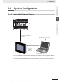
1-3 System Configuration . . . . . . . . . . . . . . . . . . . . . . . . . . . . . . . . . . . . . . . . . . 1-7
1-3-1
Connectable Peripheral Devices . . . . . . . . . . . . . . . . . . . . . . . . . . . . . . . . . . . 1-7
1-4 Procedures for NB-Series PTs’ Operation . . . . . . . . . . . . . . . . . . . . . . . . . . 1-8
NB-series Programmable Terminals NB-Designer Operation Manual(V106)
1-1
1 Introduction
1-1
Functions and Structure of NB-Series
PTs
The NB-Series Programmable Terminals (PTs) are sophisticated operator interfaces that can indicate
information and perform operations as required at FA production sites. This section provides a brief of
the roles and performances of the NB Series PTs for beginning users.
1-1-1
How NB-Series PTs Work at FA Production Sites
• Monitoring Line Operating Status
The device and operation status of the system can be displayed in real time. Using graphic charts or
other allows display data in easy-to-understand format.
• Instructing FA Staff
PTs can be used to notify system operators if there is a system or device error and to indicate
countermeasures and necessary information.
• Controlling Panel Switches
NB-Series PTs allow the users to create various kinds of switches on the displayed screen. The
values allocated to the switches can be sent to the host by clicking the switches.
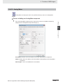
1-1-2
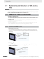
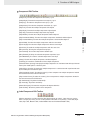
Operations of NB-Series PTs
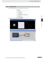
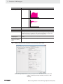
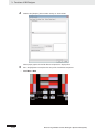
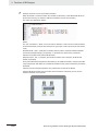
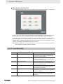
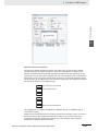
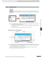
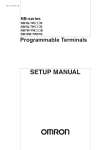
z Transferring Screen Data
The screen data displayed on NB-Series PTs is created by using NB-Designer in the PC. The
screen data is transferred to the NB units through the USB, Ethernet, and the RS-232C or using
USB memory.
Create screen data.
USB, Ethernet, RS-232C
or USB memory
Computer
(NB-Designer)
Screen data
Only when transferring screen data or using the
NB-Designer, the computer can connect with PT.
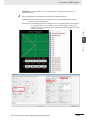
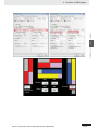
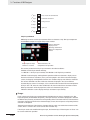
z Displaying Screens
The data to be displayed on the screens is created by using NB-Designer in PC and the data is
transferred to the PT. The required screen can be displayed by a command from the host or by
operating the touch switches.
Host
The required screens can be displayed by
using commands from the host or touch
switch operations.
1-2
NB-series Programmable Terminals NB-Designer Operation Manual(V106)
1 Introduction
1-1 Functions and Structure of
NB-Series PTs
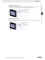
z Reading Data from the Host
NB-Series PTs can be connected to the host by using communication methods such as RS-232C,
RS-485, RS-422A, or Ethernet to automatically read the required data from the host.
RS232, RS485, RS422,
or Ethernet
Host
1
The data entered from the touch panel (ON/OFF button status, numeric data and character strings)
can be sent to the host.
Host
ON/OFF status,
numeric data, etc.
Touch panel
NB-series Programmable Terminals NB-Designer Operation Manual(V106)
1-3
1-1-2 Operations of NB-Series PTs
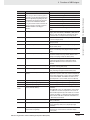
z Sending Data to the Host
1 Introduction
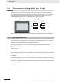
1-2
Communicating with the Host
With NB-series PTs, data required for display can be accessed and the words and bits where the
entered data will be stored can be allocated to any area in the PLC. The operations include the direct
reading and writing of the allocated words and bits, the modification of the display status for the
functional objects on the PT screen, and the control and report of the PT status.
NB-Series PT
PLC
DM area
Auxiliary area
I/O area
timers/counters
NB-Series PTs can be connected to the PLC manufactured by OMRON using the Host Link method.
1-2-1
What’s the Host Link?
The Host Link is a kind of optimized and economical communication method for FA system, which is
applicable to link one PT with one PLC or more. The PC can be used to transfer programs to the PLC,
monitor the data area of PLC and control the operation of PLC.
In the system using Host Link system, one PT sends Host Link commands to the PLC and the
commands' processing is completed followed by returning the results of the processing by the PLC (the
host).
System Features:
Connection method: RS-232C or RS-422A
Transmission rate (baud rate): 4800, 9600, 14400, 19200, 38400, 56000, 57600, 115200 and 187500
bps.
The transmission rates of 14400, 56000 and 187500 bps are not supported by the PLC manufactured
by OMRON.
Host monitoring: The PC can be used to transfer or read the PLC programs, and perform reading and
writing of the data area of PLC.
Error check system: Both parity and frame check are performed to estimate the errors occurring during
all the communications.
1-4
NB-series Programmable Terminals NB-Designer Operation Manual(V106)
1 Introduction
1-2 Communicating with the
Host
1-2-2
Connecting Methods
RS-232C
RS-232C is a kind of serial physical interface standard formulated by Electric Industry Association
(EIA).
RS-485
RS-485 uses the differential signal negative logic and the common 2-wire method, and the connectable
node on the same bus is up to 32. The master-slave communication method, i.e. one master
communicating with multiple slaves, is generally used in the RS-485 communication network.
RS-485 and RS-422A methods can realize 1:N communication, i.e. one host communicating with
multiple PLCs or PTs. The maximum number of PLCs or PTs that can be connected to the host is up to
32, and the maximum transmission distance is 500 meters.
RS-485 is half-duplex communication method that cannot allow the transmission and receiving to be
performed simultaneously.
RS-422A
It is unnecessary to control the data direction due to 4-wire RS-422A interface using separate
transmission and receiving channels. Any necessary signal exchange among the equipments can be
performed by using software method (XON/XOFF Handshaking) or hardware method (control wires).
RS-422A standard with its full name “Electrical Characteristics of Balanced Voltage Digital Interface
Circuits” specifies the characteristics of the interface circuit. Actually, there is also a signal ground, total
5 wires. Because the receiver uses high input impedance and the driving performance of the
transmission driver is more powerful than that of RS-232C, therefore the same transmission wire can
be connected with multiple receiving nodes, and the number of the connectable node is up to 10. That’s
to say, one is the master and the others are the slaves. Due to the RS-422A which is impossible to
communicate between the slaves, therefore the RS-422A supports one-point-to-multiple full-duplex
communications.
Ethernet
Ethernet is a kind of baseband LAN specification, established by Xerox company and jointly developed
by Xerox, Intel and DEC companies, which is the most common communication protocol standard
adopted by the existing LANs. PT uses the standard UTP as the transmission media for the Ethernet.
The NB Series use UTP cables.
The network communications between PT and PLC can be realized through the Ethernet connection.
Connecting the PT and the PLC manufactured by OMRON through the Ethernet allows the data read
and written. What’s more, connecting the PT with PC via the Ethernet can also perform the project
upload/download and the system processing.
NB-series Programmable Terminals NB-Designer Operation Manual(V106)
1-5
1
1-2-2 Connecting Methods
RS-232C method is based on 1:1 communication, which is applied to the point-to-point communication
within 15-meter distance due to the existence of common-ground noise and the unavoidable commonmode interference etc.
1 Introduction
1-2-3
Communicating with the PLC Manufactured by Other Companies
Besides the connection with the PLC manufactured by OMRON, NB-Series PTs can also communicate
with the devices manufactured by SIEMENS, Mitsubishi Electric Corporation, Schneider Electric, Ltd.,
Delta, Panasonic, Allen-Bradley, GE Fanuc Automation Inc., LG and the PLCs supporting Modbus
protocol. For the manufacturers and the models of the PLCs that can be communicated with, refer to
[NB Series Host Connection Manual].
1-6
NB-series Programmable Terminals NB-Designer Operation Manual(V106)
1 Introduction
1-3-1
1-3 System Configuration
1-3
System Configuration
Connectable Peripheral Devices
1
1-3-1 Connectable Peripheral Devices
Host
RS-232C cable (15m max.)
RS-485/RS422 cable (500m max.)
Ethernet *2
With NB-Designer Software installed
RS-232C cable
USB cable *1
Ethernet *2
USB memory
NB Unit
PC
Running Windows XP/Vista/7
*1 When using USB to connect NB Unit with the computer, please refer to 2-3-2 Connecting by USB in NB Series
Setup Manual.
*2 When connecting NB
-TW01B and the Host through the Ethernet, the Host should support the Ethernet
communications.
NB-series Programmable Terminals NB-Designer Operation Manual(V106)
1-7
1 Introduction
1-4
Procedures for NB-Series PTs’
Operation
Perform the following procedures to operate the NB-Series PTs.
Host
PT
Host setting
NB-Designer
Installation on the
computer
Panel installation
See 2-1-2 Installation onto the Operation panel
in the NB Series Setup Manual
See Section2 Installation and
Startup of NB-Designer
Peripheral connections
• Host link
See 2-4 Communication Connections
in the NB Series Setup Manual
• Connect to other company's PLC
See NB Series Host Connection Manual
Power connections
Screen creation
See 2-1-3 Connecting the Power Supply
in the NB Series Setup Manual
See Section3 Functions of
NB-Designer
Power ON *1
Kernel and Rootfs
installation *2
See Section4 Functions of NB Manager
Transferring to system
setting mode *3
See Section3 System Setting Mode
in the NB Series Setup Manual
Tranferring to user
project mode
Screen transfer
Host connections
See 3-15 Download
PT connections
Settings/com check
Programming
Operation
System
maintenance *4
*1 The system will enter RUN mode after the screen data is input.
*2 System program is installed only under special circumstances, such as when the system program is
transformed or repaired.
*3 The system setting mode can be entered by using the DIP SW on the back side.
*4 When the abnormalities occur during the operation, the operations such as checking input/output and
confirming the setting state etc can be performed as required.
1-8
NB-series Programmable Terminals NB-Designer Operation Manual(V106)
Ü
Installation and Startup of NBDesigner
2
The NB-Designer software needs to be installed on your computer when you use it for
the first time.
NB-Designer is a kind of application software running in Windows XP/Vista/ 7 developed
by Microsoft Corporation.
2-1 Before Installation . . . . . . . . . . . . . . . . . . . . . . . . . . . . . . . . . . . . . . . . . . . . . 2-2
2-2 Installation/Uninstallation . . . . . . . . . . . . . . . . . . . . . . . . . . . . . . . . . . . . . . . 2-3
2-2-1
2-2-2
Installation Procedure . . . . . . . . . . . . . . . . . . . . . . . . . . . . . . . . . . . . . . . . . . . 2-3
Uninstallation Procedure . . . . . . . . . . . . . . . . . . . . . . . . . . . . . . . . . . . . . . . . . 2-3
2-3 Startup & Quit . . . . . . . . . . . . . . . . . . . . . . . . . . . . . . . . . . . . . . . . . . . . . . . . . 2-4
2-3-1
2-3-2
Starting Method . . . . . . . . . . . . . . . . . . . . . . . . . . . . . . . . . . . . . . . . . . . . . . . . 2-4
Quitting Method . . . . . . . . . . . . . . . . . . . . . . . . . . . . . . . . . . . . . . . . . . . . . . . . 2-4
2-4 Installation of USB Driver for NB . . . . . . . . . . . . . . . . . . . . . . . . . . . . . . . . . 2-5
NB-series Programmable Terminals NB-Designer Operation Manual(V106)
2-1
2 Installation and Startup of NB-Designer
2-1
Before Installation
The system environment to run the NB-Designer is as follows.
System Configuration
Items
2-2
Minimum Configurations
Operating System (OS)
Microsoft Windows XP (SP3 or higher)
Microsoft Windows Vista (32-bit or 64-bit edition)
Microsoft Windows 7 (32-bit or 64-bit edition)
CPU
Intel Pentium II or higher
Memory
512 MB or more
Hard Disk
2.5 GB or more, with the disk space more than 800 MB at least
Display
Supports the display with resolution of 800×600 and 16-bit high color
(1024×768 and 32-bit true color are recommended.) .
RS-232C COM Port
One port or more is kept for the serial communication used by the
touch panel.
USB Port
USB 1.1 or higher
CD-ROM Drive
4x or higher
NB-series Programmable Terminals NB-Designer Operation Manual(V106)
2 Installation and Startup of NB-Designer
2-2-1
Installation/Uninstallation
2-2 Installation/Uninstallation
2-2
Installation Procedure
1
Start Windows XP/Windows Vista/Windows 7.
2
Double click [Setup_NBD_V] to perform the installation.
Note For download the application programs, please access your local OMRON website. If local site
cannot be found, please access OMRON IA global site “http://www.ia.omron.com/” at first and select
the area where you are.
Select your language to use the program in the [Choose Installation Language] window, and
click NEXT.
4
Click the [Next] again to display the [Select the Destination Location] dialog box.
5
After selecting default of the installing location, click the [Next].
6
7
8
9
2-2-1 Installation Procedure
3
To select another available location to install, click [Browse]. After a folder list appears, select an
available folder to install NB-Designer. Then click the [OK] and followed by [Next].
When [Ready to install the program] dialog box appears, click [Install] to start installation.
When [InstallShield Wizard is completed] dialog box appears, click [Finish] to complete the
installation.
Start NB-Designer on Windows XP, Windows Vista, or Windows 7.
The NB-Designer supports Windows XP, Windows Vista, or Windows 7.
If you use NB-Designer on Windows Vista or Windows 7, note the point as follows.
(a) If you use NB-Designer on Windows Vista or Windows 7, run NB-Designer as the administrator.
(b) If you have a compatibility problem when starting the NB-Designer, execute the software in compatible mode. Right-click on the icon of NB-Designer.exe and select [Property]. Then select
[Compatibility] tab and check the [Execute the program in compatible mode] check box in compatible mode option. Select [Windows XP(Service Park 3)] from the drop-down list and click
[OK].
(c) If you startup the NB-Designer for the first time, right-click [NB-Designer.exe] in the folder which
you specified when installing the program and click [Execute as the administrator] to start the
software.
2-2-2
Uninstallation Procedure
Perform [Uninstall or change a program] in Windows.
Note When using new-version software to update a project created with software of an old version, backup
necessarily the project before update.
Precautions for Correct Use
In order to use the product correctly, when running the software, do not perform definitely
update, restoration, uninstallation, and reinstallation.
NB-series Programmable Terminals NB-Designer Operation Manual(V106)
2
2-3
2 Installation and Startup of NB-Designer
2-3
Startup & Quit
This section provides a brief for startup and quit of NB-Designer.
2-3-1
Starting Method
Select [Start]-[All Programs]-[OMRON]-[NB-Designer]-[NB-Designer]. The startup can also be realized
by double clicking the shortcut icon
on the desktop.
• The user should run this program as an administrator in Windows Vista or Windows 7 operating
system.
• When the NB-Designer is started for the second time, the project operated last time will be opened
automatically.
• During the first launch of NB-Designer, the following screen will be displayed.
2-3-2
Quitting Method
To quit the NB-Designer can be realized by using any one of the following methods.
• Select [Exit] in the [File] menu.
• Click the button in the upper right corner of the main window.
• Double click the NB-Designer icon in the upper left corner of the main window.
• Click the NB-Designer icon in the upper left corner of the main window, and select [Close] from the
displayed control menu bar.
• Press the [Alt] key and [F4] key simultaneously.
Note When the edited data in the file is not saved, “Save the Current Project?” dialog box will pop up.
2-4
NB-series Programmable Terminals NB-Designer Operation Manual(V106)
2 Installation and Startup of NB-Designer
Installation of USB Driver for NB
Install the USB driver for NB on PC.
After the installation, the data transmission between the PC and the NB Unit is available via USB.
Because the USB driver included in the NB-Designer is certified by Microsoft, it will be installed
automatically accompanying with the software installation, so there is no need to install the USB driver
by manual again.
z Operating procedure
1
2
2
After the USB slave for the NB Unit and the computer are connected by the USB cable, “Found
New Hardware Wizard” will be displayed on PC. After selecting [Install the software
automatically (Recommended)], click the [Next] button.
USB driver is being installed.
NB-series Programmable Terminals NB-Designer Operation Manual(V106)
2-4 Installation of USB Driver for NB
2-4
2-5
2 Installation and Startup of NB-Designer
3
After the completion of installation, the following dialog box will be displayed. Click the [Close]
button.
z When the above-mentioned installation methods don’t work.
1
2-6
After the USB slave for the NB Unit and the computer are connected by the USB cable, “Update
Driver Software” will be displayed on PC. After selecting [Browse my computer for driver
software].
NB-series Programmable Terminals NB-Designer Operation Manual(V106)
2 Installation and Startup of NB-Designer
The following dialog box is displayed. Select [Include subfolders] and click the [Browse] button to
specify the folder.
Specify the driver folder under NB-Designer installation directly and click [Next] button.
2-4 Installation of USB Driver for NB
2
2
USB driver is being installed.
NB-series Programmable Terminals NB-Designer Operation Manual(V106)
2-7
2 Installation and Startup of NB-Designer
4
After the completion of installation, the following dialog box will appear. Click the [Close] button.
You can check whether the USB driver is installed successfully by selecting “Computer /
Manage / Hardware / Device Manager / Universal Serial Bus controllers” location, as shown
below.
2-8
NB-series Programmable Terminals NB-Designer Operation Manual(V106)
Functions of NB-Designer
3
This section describes the functions of NB-Designer.
3-1 User Screen . . . . . . . . . . . . . . . . . . . . . . . . . . . . . . . . . . . . . . . . . . . . . . . . . . 3-4
3-2 Menus . . . . . . . . . . . . . . . . . . . . . . . . . . . . . . . . . . . . . . . . . . . . . . . . . . . . . . . 3-7
3-2-1
3-2-2
3-2-3
3-2-4
3-2-5
3-2-6
3-2-7
3-2-8
3-2-9
3-2-10
File Menu . . . . . . . . . . . . . . . . . . . . . . . . . . . . . . . . . . . . . . . . . . . . . . . . . . . . . 3-7
Edit Menu . . . . . . . . . . . . . . . . . . . . . . . . . . . . . . . . . . . . . . . . . . . . . . . . . . . . 3-10
View Menu . . . . . . . . . . . . . . . . . . . . . . . . . . . . . . . . . . . . . . . . . . . . . . . . . . . 3-15
Screen Menu . . . . . . . . . . . . . . . . . . . . . . . . . . . . . . . . . . . . . . . . . . . . . . . . . 3-26
Draw Menu . . . . . . . . . . . . . . . . . . . . . . . . . . . . . . . . . . . . . . . . . . . . . . . . . . 3-29
Components Menu . . . . . . . . . . . . . . . . . . . . . . . . . . . . . . . . . . . . . . . . . . . . 3-29
Tools Menu . . . . . . . . . . . . . . . . . . . . . . . . . . . . . . . . . . . . . . . . . . . . . . . . . . 3-30
Option Menu . . . . . . . . . . . . . . . . . . . . . . . . . . . . . . . . . . . . . . . . . . . . . . . . . 3-30
Window Menu . . . . . . . . . . . . . . . . . . . . . . . . . . . . . . . . . . . . . . . . . . . . . . . . 3-31
Help Menu . . . . . . . . . . . . . . . . . . . . . . . . . . . . . . . . . . . . . . . . . . . . . . . . . . . 3-32
3-3 NB-Designer Software Window . . . . . . . . . . . . . . . . . . . . . . . . . . . . . . . . . 3-33
3-3-1
3-3-2
3-3-3
3-3-4
3-3-5
Project Library Window . . . . . . . . . . . . . . . . . . . . . . . . . . . . . . . . . . . . . . . . .
Project File Window . . . . . . . . . . . . . . . . . . . . . . . . . . . . . . . . . . . . . . . . . . . .
Project Work Space . . . . . . . . . . . . . . . . . . . . . . . . . . . . . . . . . . . . . . . . . . . .
Output Window . . . . . . . . . . . . . . . . . . . . . . . . . . . . . . . . . . . . . . . . . . . . . . .
Component List Window . . . . . . . . . . . . . . . . . . . . . . . . . . . . . . . . . . . . . . . .
3-33
3-37
3-37
3-43
3-44
3-4 Screen Concept . . . . . . . . . . . . . . . . . . . . . . . . . . . . . . . . . . . . . . . . . . . . . . 3-45
3-4-1
3-4-2
3-4-3
3-4-4
3-4-5
3-4-6
Screen Types . . . . . . . . . . . . . . . . . . . . . . . . . . . . . . . . . . . . . . . . . . . . . . . . .
Screen Property . . . . . . . . . . . . . . . . . . . . . . . . . . . . . . . . . . . . . . . . . . . . . . .
Screen Creation . . . . . . . . . . . . . . . . . . . . . . . . . . . . . . . . . . . . . . . . . . . . . . .
Screen Opening . . . . . . . . . . . . . . . . . . . . . . . . . . . . . . . . . . . . . . . . . . . . . . .
Screen Deletion . . . . . . . . . . . . . . . . . . . . . . . . . . . . . . . . . . . . . . . . . . . . . . .
Components Related to Screen . . . . . . . . . . . . . . . . . . . . . . . . . . . . . . . . . . .
3-45
3-48
3-52
3-52
3-53
3-53
3-5 Basic Design Method . . . . . . . . . . . . . . . . . . . . . . . . . . . . . . . . . . . . . . . . . . 3-54
3-5-1
3-5-2
3-5-3
3-5-4
3-5-5
3-5-6
3-5-7
Designing Components . . . . . . . . . . . . . . . . . . . . . . . . . . . . . . . . . . . . . . . . .
About ID No. . . . . . . . . . . . . . . . . . . . . . . . . . . . . . . . . . . . . . . . . . . . . . . . . .
Additional Comments (Descriptions) . . . . . . . . . . . . . . . . . . . . . . . . . . . . . . .
Read/Write Address for PLC . . . . . . . . . . . . . . . . . . . . . . . . . . . . . . . . . . . . .
Vector Graphic . . . . . . . . . . . . . . . . . . . . . . . . . . . . . . . . . . . . . . . . . . . . . . . .
Bitmap . . . . . . . . . . . . . . . . . . . . . . . . . . . . . . . . . . . . . . . . . . . . . . . . . . . . . .
Creating Label . . . . . . . . . . . . . . . . . . . . . . . . . . . . . . . . . . . . . . . . . . . . . . . .
NB-series Programmable Terminals NB-Designer Operation Manual(V106)
3-54
3-55
3-56
3-57
3-58
3-63
3-66
3-1
3 Functions of NB-Designer
3-5-8
3-5-9
3-5-10
3-5-11
3-5-12
Task Bar and Operation Buttons . . . . . . . . . . . . . . . . . . . . . . . . . . . . . . . . . . . 3-68
Fonts . . . . . . . . . . . . . . . . . . . . . . . . . . . . . . . . . . . . . . . . . . . . . . . . . . . . . . . . 3-70
Basic Properties of Component . . . . . . . . . . . . . . . . . . . . . . . . . . . . . . . . . . . 3-73
Control Setting of Component . . . . . . . . . . . . . . . . . . . . . . . . . . . . . . . . . . . . . 3-74
Display Setting of Component . . . . . . . . . . . . . . . . . . . . . . . . . . . . . . . . . . . . . 3-78
3-6 Parts . . . . . . . . . . . . . . . . . . . . . . . . . . . . . . . . . . . . . . . . . . . . . . . . . . . . . . . . 3-80
3-6-1
3-6-2
3-6-3
3-6-4
3-6-5
3-6-6
3-6-7
3-6-8
3-6-9
3-6-10
3-6-11
3-6-12
3-6-13
3-6-14
3-6-15
3-6-16
3-6-17
3-6-18
3-6-19
3-6-20
3-6-21
3-6-22
3-6-23
3-6-24
3-6-25
3-6-26
3-6-27
3-6-28
3-6-29
Bit Button . . . . . . . . . . . . . . . . . . . . . . . . . . . . . . . . . . . . . . . . . . . . . . . . . . . . . 3-80
Bit Lamp . . . . . . . . . . . . . . . . . . . . . . . . . . . . . . . . . . . . . . . . . . . . . . . . . . . . . 3-83
Bit Switch . . . . . . . . . . . . . . . . . . . . . . . . . . . . . . . . . . . . . . . . . . . . . . . . . . . . 3-86
Command Button . . . . . . . . . . . . . . . . . . . . . . . . . . . . . . . . . . . . . . . . . . . . . . 3-87
Word Lamp . . . . . . . . . . . . . . . . . . . . . . . . . . . . . . . . . . . . . . . . . . . . . . . . . . . 3-92
Word Switch . . . . . . . . . . . . . . . . . . . . . . . . . . . . . . . . . . . . . . . . . . . . . . . . . . 3-94
XY Graph . . . . . . . . . . . . . . . . . . . . . . . . . . . . . . . . . . . . . . . . . . . . . . . . . . . . 3-98
Moving Component . . . . . . . . . . . . . . . . . . . . . . . . . . . . . . . . . . . . . . . . . . . . 3-107
Animation . . . . . . . . . . . . . . . . . . . . . . . . . . . . . . . . . . . . . . . . . . . . . . . . . . . 3-112
Number Input . . . . . . . . . . . . . . . . . . . . . . . . . . . . . . . . . . . . . . . . . . . . . . . . 3-114
Number Display . . . . . . . . . . . . . . . . . . . . . . . . . . . . . . . . . . . . . . . . . . . . . . . 3-120
Text Input . . . . . . . . . . . . . . . . . . . . . . . . . . . . . . . . . . . . . . . . . . . . . . . . . . . . 3-123
Text Display . . . . . . . . . . . . . . . . . . . . . . . . . . . . . . . . . . . . . . . . . . . . . . . . . . 3-127
Level Meter . . . . . . . . . . . . . . . . . . . . . . . . . . . . . . . . . . . . . . . . . . . . . . . . . . 3-128
Analog Meter . . . . . . . . . . . . . . . . . . . . . . . . . . . . . . . . . . . . . . . . . . . . . . . . . 3-139
Indirect Screen . . . . . . . . . . . . . . . . . . . . . . . . . . . . . . . . . . . . . . . . . . . . . . . 3-143
Direct Screen . . . . . . . . . . . . . . . . . . . . . . . . . . . . . . . . . . . . . . . . . . . . . . . . 3-146
Alarm . . . . . . . . . . . . . . . . . . . . . . . . . . . . . . . . . . . . . . . . . . . . . . . . . . . . . . . 3-148
Data Log . . . . . . . . . . . . . . . . . . . . . . . . . . . . . . . . . . . . . . . . . . . . . . . . . . . . 3-150
Recipe . . . . . . . . . . . . . . . . . . . . . . . . . . . . . . . . . . . . . . . . . . . . . . . . . . . . . . 3-160
Oscillograph . . . . . . . . . . . . . . . . . . . . . . . . . . . . . . . . . . . . . . . . . . . . . . . . . 3-160
Scroll Bar . . . . . . . . . . . . . . . . . . . . . . . . . . . . . . . . . . . . . . . . . . . . . . . . . . . . 3-164
Event . . . . . . . . . . . . . . . . . . . . . . . . . . . . . . . . . . . . . . . . . . . . . . . . . . . . . . . 3-167
Note Book . . . . . . . . . . . . . . . . . . . . . . . . . . . . . . . . . . . . . . . . . . . . . . . . . . . 3-174
Word Neon Lamp . . . . . . . . . . . . . . . . . . . . . . . . . . . . . . . . . . . . . . . . . . . . . 3-185
Bit Neon Lamp . . . . . . . . . . . . . . . . . . . . . . . . . . . . . . . . . . . . . . . . . . . . . . . 3-186
Touch Trigger . . . . . . . . . . . . . . . . . . . . . . . . . . . . . . . . . . . . . . . . . . . . . . . . . 3-187
Table . . . . . . . . . . . . . . . . . . . . . . . . . . . . . . . . . . . . . . . . . . . . . . . . . . . . . . . 3-189
Data History . . . . . . . . . . . . . . . . . . . . . . . . . . . . . . . . . . . . . . . . . . . . . . . . . 3-190
3-7 Function Parts . . . . . . . . . . . . . . . . . . . . . . . . . . . . . . . . . . . . . . . . . . . . . . . 3-196
3-7-1
3-7-2
3-7-3
3-7-4
3-7-5
3-7-6
3-7-7
3-7-8
3-7-9
3-7-10
3-7-11
3-7-12
3-7-13
3-7-14
Scale . . . . . . . . . . . . . . . . . . . . . . . . . . . . . . . . . . . . . . . . . . . . . . . . . . . . . . . 3-196
Function Key . . . . . . . . . . . . . . . . . . . . . . . . . . . . . . . . . . . . . . . . . . . . . . . . . 3-197
Alarm Display . . . . . . . . . . . . . . . . . . . . . . . . . . . . . . . . . . . . . . . . . . . . . . . . 3-205
Timer . . . . . . . . . . . . . . . . . . . . . . . . . . . . . . . . . . . . . . . . . . . . . . . . . . . . . . . 3-209
Bitmap . . . . . . . . . . . . . . . . . . . . . . . . . . . . . . . . . . . . . . . . . . . . . . . . . . . . . . 3-214
Vector Graphics . . . . . . . . . . . . . . . . . . . . . . . . . . . . . . . . . . . . . . . . . . . . . . . 3-215
Notepad . . . . . . . . . . . . . . . . . . . . . . . . . . . . . . . . . . . . . . . . . . . . . . . . . . . . . 3-216
Data Transmission . . . . . . . . . . . . . . . . . . . . . . . . . . . . . . . . . . . . . . . . . . . . . 3-219
Freeplotting . . . . . . . . . . . . . . . . . . . . . . . . . . . . . . . . . . . . . . . . . . . . . . . . . . 3-222
Date/Time . . . . . . . . . . . . . . . . . . . . . . . . . . . . . . . . . . . . . . . . . . . . . . . . . . . 3-223
Indirect Shape . . . . . . . . . . . . . . . . . . . . . . . . . . . . . . . . . . . . . . . . . . . . . . . . 3-225
User Information . . . . . . . . . . . . . . . . . . . . . . . . . . . . . . . . . . . . . . . . . . . . . . 3-229
Multifunction . . . . . . . . . . . . . . . . . . . . . . . . . . . . . . . . . . . . . . . . . . . . . . . . . 3-229
Event Display . . . . . . . . . . . . . . . . . . . . . . . . . . . . . . . . . . . . . . . . . . . . . . . . 3-232
3-8 Project Database . . . . . . . . . . . . . . . . . . . . . . . . . . . . . . . . . . . . . . . . . . . . . 3-234
3-8-1
3-8-2
3-8-3
3-2
Text Library . . . . . . . . . . . . . . . . . . . . . . . . . . . . . . . . . . . . . . . . . . . . . . . . . . 3-234
Variable Table . . . . . . . . . . . . . . . . . . . . . . . . . . . . . . . . . . . . . . . . . . . . . . . . 3-240
Alarm Setting . . . . . . . . . . . . . . . . . . . . . . . . . . . . . . . . . . . . . . . . . . . . . . . . 3-243
NB-series Programmable Terminals NB-Designer Operation Manual(V106)
3 Functions of NB-Designer
3-8-4
3-8-5
Event Setting . . . . . . . . . . . . . . . . . . . . . . . . . . . . . . . . . . . . . . . . . . . . . . . . 3-248
PLC Control . . . . . . . . . . . . . . . . . . . . . . . . . . . . . . . . . . . . . . . . . . . . . . . . . 3-252
3-9 Macro Function . . . . . . . . . . . . . . . . . . . . . . . . . . . . . . . . . . . . . . . . . . . . . 3-260
3-9-1
3-9-2
3-9-3
3-9-4
Create a Simple Macro Program . . . . . . . . . . . . . . . . . . . . . . . . . . . . . . . . .
Macro and Specification of Operation with Read/Write Variables . . . . . . . .
Macro Triggering . . . . . . . . . . . . . . . . . . . . . . . . . . . . . . . . . . . . . . . . . . . . .
Other Descriptions . . . . . . . . . . . . . . . . . . . . . . . . . . . . . . . . . . . . . . . . . . . .
3-260
3-267
3-268
3-270
3-10 System Parameters . . . . . . . . . . . . . . . . . . . . . . . . . . . . . . . . . . . . . . . . . . 3-283
3-10-1
3-10-2
3-10-3
3-10-4
3-10-5
3-10-6
3-10-7
3-10-8
PT . . . . . . . . . . . . . . . . . . . . . . . . . . . . . . . . . . . . . . . . . . . . . . . . . . . . . . . .
Task Bar . . . . . . . . . . . . . . . . . . . . . . . . . . . . . . . . . . . . . . . . . . . . . . . . . . . .
PT Extended Properties . . . . . . . . . . . . . . . . . . . . . . . . . . . . . . . . . . . . . . .
System Information Setting . . . . . . . . . . . . . . . . . . . . . . . . . . . . . . . . . . . . .
Security Levels Setting . . . . . . . . . . . . . . . . . . . . . . . . . . . . . . . . . . . . . . . .
User Permission Setting . . . . . . . . . . . . . . . . . . . . . . . . . . . . . . . . . . . . . . .
Event History Setting . . . . . . . . . . . . . . . . . . . . . . . . . . . . . . . . . . . . . . . . . .
COM1/COM2 Setting . . . . . . . . . . . . . . . . . . . . . . . . . . . . . . . . . . . . . . . . . .
3-284
3-285
3-287
3-296
3-298
3-300
3-314
3-315
3-11 Address of System Memory . . . . . . . . . . . . . . . . . . . . . . . . . . . . . . . . . . . 3-317
3-11-1
3-11-2
3-11-3
3-11-4
Local Bit (LB) . . . . . . . . . . . . . . . . . . . . . . . . . . . . . . . . . . . . . . . . . . . . . . . .
Local Word (LW) . . . . . . . . . . . . . . . . . . . . . . . . . . . . . . . . . . . . . . . . . . . . .
Nonvolatile Local Word (LW10000~10255) . . . . . . . . . . . . . . . . . . . . . . . . .
System Information Table . . . . . . . . . . . . . . . . . . . . . . . . . . . . . . . . . . . . . .
3-318
3-322
3-325
3-327
3-12 Recipe Data . . . . . . . . . . . . . . . . . . . . . . . . . . . . . . . . . . . . . . . . . . . . . . . . . 3-329
3-12-1
3-12-2
3-12-3
Process of Creating One Recipe Component . . . . . . . . . . . . . . . . . . . . . . . 3-329
Recipe Memory . . . . . . . . . . . . . . . . . . . . . . . . . . . . . . . . . . . . . . . . . . . . . . 3-331
Upload/Download of Recipe Data between PT and PLC . . . . . . . . . . . . . . 3-335
3-13 Security Level . . . . . . . . . . . . . . . . . . . . . . . . . . . . . . . . . . . . . . . . . . . . . . . 3-340
3-14 Test . . . . . . . . . . . . . . . . . . . . . . . . . . . . . . . . . . . . . . . . . . . . . . . . . . . . . . . 3-346
3-14-1
3-14-2
3-14-3
Offline test . . . . . . . . . . . . . . . . . . . . . . . . . . . . . . . . . . . . . . . . . . . . . . . . . . 3-346
Direct Online test . . . . . . . . . . . . . . . . . . . . . . . . . . . . . . . . . . . . . . . . . . . . . 3-347
Indirect Online test . . . . . . . . . . . . . . . . . . . . . . . . . . . . . . . . . . . . . . . . . . . . 3-348
3-15 Download . . . . . . . . . . . . . . . . . . . . . . . . . . . . . . . . . . . . . . . . . . . . . . . . . . 3-349
3-15-1
3-15-2
3-15-3
Transmission Setting . . . . . . . . . . . . . . . . . . . . . . . . . . . . . . . . . . . . . . . . . . 3-349
Download via USB Memory . . . . . . . . . . . . . . . . . . . . . . . . . . . . . . . . . . . . . 3-351
Specification of Downloading Contents . . . . . . . . . . . . . . . . . . . . . . . . . . . . 3-351
3-16 Other Functions . . . . . . . . . . . . . . . . . . . . . . . . . . . . . . . . . . . . . . . . . . . . . 3-355
3-17 RecipeEditor . . . . . . . . . . . . . . . . . . . . . . . . . . . . . . . . . . . . . . . . . . . . . . . . 3-397
NB-series Programmable Terminals NB-Designer Operation Manual(V106)
3-3
3
3 Functions of NB-Designer
3-1
User Screen
The displayed contents in the screen are shown as below when the NB-Designer is running.
You can also right-click [View] - [Toolbar] or toolbar to see each toolbar shown as below.
Title
Menu
Toolbar
Project file
window
Project Library
window
Edit
window
Project Work
Space
Output
window
Component list
window
Status bar
z Title
Editing project file name and others are displayed.
z Menu
Selects the various kinds of command menus of NB-Designer. After these menus being selected,
the corresponding pull-down menu will pop up. Each pull-down menu corresponds to one command
operation.
3-4
NB-series Programmable Terminals NB-Designer Operation Manual(V106)
3 Functions of NB-Designer
z Toolbar
1
Common Toolbar
Includes some basic tools such as “New”, “Open”, “Cut” and “Copy” etc.
2
Draw Toolbar
3
Screen Toolbar
Performs Up/Down operation of the screen.
4
Component Edit Toolbar
3
Adjusts the position of the component (i.e. top-alignment, bottom-alignment, left-alignment,
right-alignment etc), the size, cascading, combination and flip methods.
5
Line Width Toolbar
Adjusts the width of the line in the figure.
6
Line Style Toolbar
Add or delete the arrow head, replace solid line with broken line in the figures.
7
System Toolbar
Performs the compilation, downloading and test of the project.
8
Database Toolbar
Includes text library, alarm information, Variable Table, PLC control and event information.
9
3-1 User Screen
Each image of figure drawing is displayed in icons. The available drawing tools include Line,
Rectangle, Ellipse, Sector, Polygon, Text etc.
Code Edit Toolbar
The icon to edit macro is displayed.
10 Pattern Toolbar
Select the filling-style of screen background or the closed space such as rectangle, ellipse,
sector etc.
11 Label Component Edit Toolbar
Performs the alignments of the label such as label aligning to the left-border/right-border/topborder or bottom-border of the component, label locating in the vertical center or horizontal
center of the component.
12 State Switch Toolbar
Simulates the switching of the various states of each component in the current screen and
languages.
13 Font Toolbar
Sets dot matrix/vector/graphics mode, font and font size of various kinds of texts displayed in
the screen.
NB-series Programmable Terminals NB-Designer Operation Manual(V106)
3-5
3 Functions of NB-Designer
14 Status Bar Toolbar
Displays the information such as the current mouse position, the width/height of the destination
object and the editing state etc.
z Project Library Window
6 columns in the Project Library Window are available.
Connector: Selects the communication cable type.
PT: Selects the PT type.
PLC: Selects the PLC type.
Parts: Selects various kinds of configuration parts.
Function Parts: Selects various kinds of multi-function parts.
Project Database: Selects some special functions.
z Project Work Space
Project Work Space adopts tree view chart to show the relations of the PLC, PT, PT internal screens
and components in the whole project.
z Project File Window
Project File Window adopts tree view to show the correlations between the PT and bitmap files
related to the project, and all the information of the files (such as the recipe files, macro files and
graphics library files etc) contained in the project.
z Output Window
For details, refer to 3-3-4 Output Window (Page 3-43).
z Component List Window
For details, refer to 3-3-1 Project Library Window (Page 3-33).
z Configuration and Setup Window, Edit Window
Users setup configurations or create drawings in the window.
3-6
NB-series Programmable Terminals NB-Designer Operation Manual(V106)
3 Functions of NB-Designer
3-2
Menus
There are various kinds of menus in NB-Designer. You can set the object, graphics, chart, macro, data
block etc, and create the screen data displayed on the NB Unit. The pull-down menu list and the
purposes of each item are as follows.
3-2-1
File Menu
Select [New] in the [File] menu or
3-2 Menus
z New
icon to create a new project.
3
3-2-1 File Menu
A new project is created when you press [OK] after inputting the project name.
z Open
Select [Open] in the [File] menu or
icon to open an existing project.
Select the project file to be opened, and press [Open] or double click this project file.
NB-series Programmable Terminals NB-Designer Operation Manual(V106)
3-7
3 Functions of NB-Designer
z Save
Select either of “Save” and “Save As”.
z Close
Select [Close] in the [File] menu to close the current project.
3-8
NB-series Programmable Terminals NB-Designer Operation Manual(V106)
3 Functions of NB-Designer
All the current windows will be closed after “Close” being pressed, and the display screen is shown
as below.
3-2 Menus
3
3-2-1 File Menu
z List up the 4 projects opened recently
z Exit
Exit the NB-Designer software.
Note When Free-editing multiple project screens, adds the multiple-project-simultaneous-opening function,
thus making the copy of the component in the editing screens of two projects available. Modifies the
zoom limit of the screen, thus making 25%, 50%, 75%, 100%, 150%, 200% and 300% available. The
uniform zoom can be realized by dragging the mouse when the multiple components are selected
simultaneously in the same screen.
NB-series Programmable Terminals NB-Designer Operation Manual(V106)
3-9
3 Functions of NB-Designer
3-2-2
Edit Menu
z Undo
The latest operation can be cancelled by using this function, and the screen will return to the state
before this operation. Pressing
icon or selecting [Undo] in the [Edit] menu can cancel the
latest operation.
z Redo
Using this function after performing “Undo” operation can restore the “Undo” operation done just
now. It just needs to press
icon or select [Redo] in the [Edit] menu.
The operations supported by “Undo” and “Redo” are as follows.
(1) Dragging a part or a functional part from the Project Library Window
(2) Drawing a component
(3) Moving the object
(4) Adjusting the object size
(5) Performing all the operations with the Component Edit Toolbar
(6) Selecting the line width, line style or arrow
(7) Selecting the object filling style
(8) Selecting the object border color
(9) Selecting the object filled color
(10)Performing “Set Top Layer” and “Set Bottom Layer” operations
(11)Performing the “Group” and “Ungroup” operations
3-10
NB-series Programmable Terminals NB-Designer Operation Manual(V106)
3 Functions of NB-Designer
(12)Performing cut, copy, paste and deletion
(13)Performing the Repeat operation
An example of operation in which a bit switch component is added to the PT screen and [Undo] or
[Redo] is performed to the addition is provided as below.
3-2 Menus
Press [Undo].
3
3-2-2 Edit Menu
Then press [Redo].
Note The software only supports single-step “Undo/Redo” operation.
z Cut, Copy, Paste and Delete
After selecting one component or more, you can cut, copy, paste it or them etc, and the
corresponding icons are shown as
.
z Nudge
The component position can be adjusted by “Nudge” method after it is selected. The component
movement can be realized by using direction key or the corresponding [Nudge] icons. Each time the
“Nudge” button is pressed, the component will move a pixel distance accordingly. The corresponding
icons are shown as
and they are “Left”, “Right”, “Up”, “Down” corresponding one-
to-one with the contents of [Nudge] in the [Edit] menu. The simple nudge method is to use the arrow
keys on the keyboard, which realizes the easy component movement.
NB-series Programmable Terminals NB-Designer Operation Manual(V106)
3-11
3 Functions of NB-Designer
z Alignment
Makes the selected component realize the Left, Right, Top, Bottom, Vertical Midline or Horizontal
Midline alignment. The corresponding icons are shown as Here
only take
“Left” as an example with the effect shown as below.
z Size
To make the multiple components with the same width, height or size, you just need to press the
corresponding icons for adjusting the size of the component, or to select the options in the
corresponding menus. The corresponding icons are shown as
and they are “Width”,
“Height” and “Both” respectively. Unify the size for all components according to the size of the
component is located in the left end among all the components. If you want to specify a certain
component as the reference, select other components after pressing the [shift] key to select the
reference.
3-12
NB-series Programmable Terminals NB-Designer Operation Manual(V106)
3 Functions of NB-Designer
z Order
When the multiple components are overlapped together, you can use the icons shown as
(Bring to Front, Send to Back, Bring Forward, Send Backward) or select [Bring to
Front], [Send to Back], [Bring Forward], [Send Backward] in [Order] of the [Edit] menu to change the
display order of the components.
Firstly select the component and set the layer of the component by pressing the corresponding icon.
The component in the front layer is always displayed above that in the back layer.
3-2 Menus
Set Top Layer
z Group/UnGroup
This function is used to make the multiple selected components or graphics combined together as a
separate component. To make multiple components combined together, it just needs to select these
components, and then select [Group] in the [Edit] menu or press
icon. To cancel the
icon.
z Horizontal Even Spacing
This function is used to make the horizontal space between the multiple selected components or
graphics same. Select the graphics or components to be operated, and then select [Horizontal Even
Spacing] in the [Edit] menu or press
icon. Clicking the icon allows the components lined as
below.
z Vertical Even Spacing
This function is used to make the vertical space between the multiple selected components or
graphics same. Select the graphics or components to be operated, and then select [Vertical Even
Spacing] in the [Edit] menu or press
icon.
NB-series Programmable Terminals NB-Designer Operation Manual(V106)
3-13
3-2-2 Edit Menu
combination, it only needs to select this combined component, then select [UnGroup] in the [Edit]
menu or press
3
3 Functions of NB-Designer
z Align Horizontal Center
This function is used to make the multiple selected components or graphics located in the horizontal
center of the Edit Window. Firstly select the components or graphics to be operated, and then select
[Align Horizontal Center] in the [Edit] menu or press
icon, as shown below.
z Align Vertical Center
This function is used to make the multiple selected components or graphics located in the vertical
center of the Edit Window. Firstly select the graphics to be operated, and then select [Align Vertical
Center] in the [Edit] menu or press
icon.
z Flip
Only shapes (such as line, circle, polygon etc) drawn by drawing tools rather than other components
can be flipped. Firstly select the graphics to be operated, and then select [Flip Horizontally], [Flip
Vertically, [Rotate 90 Degree] in the [Edit] menu or select the corresponding
icons to
flip the components.
3-14
NB-series Programmable Terminals NB-Designer Operation Manual(V106)
3 Functions of NB-Designer
z Reset Toolbars
When the toolbar is moved to the other position, it can be restored to the default position by clicking
this option, as shown below.
3-2 Menus
3
3-2-3 View Menu
3-2-3
View Menu
The options in the [View] menu are used to control the various kinds of toolbars to be displayed or not.
NB-series Programmable Terminals NB-Designer Operation Manual(V106)
3-15
3 Functions of NB-Designer
z Common Toolbar
The correspondences of all the items (i.e. the icons here) in the standard toolbar to the options in the
menus are shown as below.
About
New Project
Display Component's Name
Property
Open Project
Print
Save Project
Paste
UnDo
Cut
Copy
Delete
Repeat
ReDo
Print Preview
Find/Replace
[New Project]: To create a new project
[Open Project]: To open an existing project
[Save Project]: To save the current project
[Cut]: To perform cutting operation
[Copy]: To perform copy operation
[Paste]: To perform paste operation
[Repeat]: To perform Repeat operation
[Delete]: To delete the component
[Redo]: To restore the latest cancelled operation
[Undo]: To cancel the latest operation procedure
[Find/Replace]: To search the memory addresses used in the current project, screen or macro and
perform the replacement
[Print Preview]: To preview the print effect (The NB Series do not support this function currently.)
[Print]: To print (The NB Series do not support this function currently.)
[Property]: To show the object Properties
[Display Component’s Name]: To display/hide the component’s name
[About]: To describe the version information of NB-Designer
3-16
NB-series Programmable Terminals NB-Designer Operation Manual(V106)
3 Functions of NB-Designer
z Repeat
With this function, one component can become multiple components through the copy operation,
thus saving a lot of time. You can make the multiple components available by clicking
icon or
right-clicking [Repeat] in the corresponding menu after the component being selected, as shown
below.
3-2 Menus
3
Copy Quantity: The number of the copied component in each line and each column.
Interval between components: Specifying the horizontal interval and vertical interval between the
two of the copied components.
Offset Address: The address of the copied component increases/decreases in X, Y directions.
Word Address Auto Change: The word address of the copied component increases/decreases in X,
Y directions.
Bit Position Auto Change: The bit address of the copied component increases/decreases in X, Y
directions.
Interval: To select the address increment among the copied components.
[Property]: When changing the property of the components, select and double-click the component
which is necessary to change the property. Also clicking the
icon and displaying [Property]
dialog box allow the property of the component edited.
NB-series Programmable Terminals NB-Designer Operation Manual(V106)
3-17
3-2-3 View Menu
Copy Type: Selecting [From start point], the copied component to be arranged according to the
upper left top of the component as the reference point.
Selecting [From end point], the copied component to be arranged according to the lower right top of
the component as the reference point.
3 Functions of NB-Designer
z Database Toolbar
The correspondences of all the items (i.e. the icons here) in the toolbar to the options in the menus
are shown as below.
Edit Logo Screen
Text library
Import Recipe Data File
Variable Table
Add Macro
Alarm Setting
Sound library
Event Setting
Import Graphics
PLC Control
Add Graphics
[Text Library]: To register the text string for the labels.
[Variable Table]: To register the variable information
[Alarm Setting]: To memory the alarm information
[Event Setting]: To memory the event information
[PLC Control]: To register the PLC control configurations
[Add Graphics]: To create the new bitmap or Vector Graphics
[Import Graphics]: To import the bitmap or Vector Graphics
[Sound Library]: To add the audio file (The NB Series does not support the function.)
[Add Macro]: To add the Macro
[Import Recipe Data File]: To import the recipe file
[Edit Logo Screen]: Click this button to make the screen switch to the logo edit screen. therefore you
can make modification or editing the logo screen displayed when the PT is powered on, as shown
below.
z Line Style Toolbar
Adding or deleting the arrow head or replacing solid line with broken line.
3-18
NB-series Programmable Terminals NB-Designer Operation Manual(V106)
3 Functions of NB-Designer
z Component Edit Toolbar
[Nudge Left]: To make the component move left by 1 grid
[Nudge Right]: To make the component move right by 1 grid
[Nudge Up]: To make the component move up by 1 grid
[Nudge Down]: To make the component move down by 1 grid
[Align Left]: To make the multiple components left-aligned
3-2 Menus
[Align Right]: To make the multiple components right-aligned
[Align Top]: To make the multiple components top-aligned
[Align Bottom]: To make the multiple components bottom-aligned
[Align Horizontal Midline]: To make the multiple components horizontal-midline-aligned
3
[Align Vertical Midline]: To make the multiple components vertical-midline-aligned
[Equal Width]: To make the multiple components with the same width
3-2-3 View Menu
[Equal Height]: To make the multiple components with the same height
[Equal Size]: To make the multiple components with the same size
[Bring to Front]: To bring the component to top layer
[Send to Back]: To send the component to bottom layer
[Bring Forward]: To bring the selected component to previous layer
[Send Backward]: To send the selected component to next layer
[Group]: To make the multiple components combined together
[UnGroup]: To cancel the combination of the multiple components
[Horizontal Even Spacing]: Arranging the multiple components in a horizontal row with equal interval
each by the middle point as reference point.
[Vertical Even Spacing]: Arranging the multiple components in a vertical row with equal interval each
by the middle point as reference point.
[Align Horizontal Center]: To make the center(s) of one component or multiple components located
in the horizontal center of the PT Edit area
[Align Vertical Center]: To make the center(s) of one component or multiple components located in
the vertical center of the PT Edit area
[Flip Horizontally]: To perform horizontal flip
[Flip Vertically]: To perform vertical flip
[Rotate 90 Degree]: To rotate the component 90 degree clockwise
[Lock Position]: To lock the position of the component
z Label Component Edit Toolbar
Click the component, and then click the label displayed later to select it. Later when you see the
label is not gray any more, you can set the position of the label as required (e.g. Left Label, Right
Label, Top Label, Bottom Label, Vertical Middle Label and Horizontal Middle Label).
NB-series Programmable Terminals NB-Designer Operation Manual(V106)
3-19
3 Functions of NB-Designer
z Draw Toolbar
The contents of the items in the Draw Toolbar are shown as below.
[Select]: To select one component or multiple components
[Line]: To draw a line
[Arc]: To draw an arc
[Rect]: To draw a rectangle
[Round Rect]: To draw a rounded rectangle
[Polyline]: To draw a consecutive line
[Polygon]: To draw a polygon
[Ellipse]: To draw a circle or ellipse
[Sector]: To draw a sector
[Text]: To add the text
[Load Graphic]: To add the bitmap in the editing window
[Frame Color]: To set the frame color for the shapes
[Background Color]: To set the background color for the shapes
[Show Grid]: To make the grid displayed in the screen
[Transparent Color]: To add transparency to the added bitmap
[Multicolor-Grayscale Switch]: To make the transformation between the color and black/white
[Align with Grid]: After the component being selected, click this button once to make the grid point as
the moving unit, and click it twice to restore the default pixel point as the moving unit of the
component.
For the color setup, there are 40 kinds of colors available, as shown below.
Besides the 40 kinds of colors shown above, the custom colors are also available. The following
dialog box will be displayed after clicking “Custom Color…” at the bottom.
3-20
NB-series Programmable Terminals NB-Designer Operation Manual(V106)
3 Functions of NB-Designer
Here you can select any color you want to have. In addition, there are also several color Properties,
as shown below, available to you.
3-2 Menus
3
z Select Component
(1) Direct selection: The component can be selected by using the mouse directly to click it.
(2) Selecting all the components: All the components in the current screen can be selected by
using [Select All] in the [Edit] menu.
(3) The multiple components can be selected by clicking them consecutively while pressing the
[Shift] key.
Note The copy operation can be performed by clicking the component to be copied while pressing the [Ctrl] key.
z Modify Component Size
The modification of the component size can be made by clicking the component. The specific
method is as follows: select any one of the eight green points on the component, as shown below,
after the component being selected, and then drag it by using the mouse.
Note The white dots displayed on the component mean that the text is selected. If you should change the size of
component, click the area without a text to select whole the component.
z Fill Component and Frame
To change the frame or the background color of the shapes, it just needs to click the small arrow
behind the
“Frame Color” icon after the component being selected to change the frame color,
and to click the small arrow displayed in the right to the [Background Color] icon change the
background color of the shapes, as shown below.
NB-series Programmable Terminals NB-Designer Operation Manual(V106)
3-21
3-2-3 View Menu
The selection methods of the components are as follows.
3 Functions of NB-Designer
z Text
After the text icon
being pressed, the text dialog box will pop up, as shown below.
Message: Enter the text which will be displayed on the component. You can use the “Enter” key to
break the input text.
Graphic Font: The font and its size and style etc can be modified in this mode. The Modify dialog box, as
shown below, can be entered by clicking the “Font” on the right side of “Graphic Font”.
3-22
NB-series Programmable Terminals NB-Designer Operation Manual(V106)
3 Functions of NB-Designer
Transport Font: In this mode, both Vector Font and Bitmap Font can be used, and the font size,
alignment method or color etc can be changed.
3-2 Menus
3
3-2-3 View Menu
z Load Graphic
The
icon can be used to add the graphic when you create a new bitmap. For the creation of the
bitmap, refer to 3-5-6 Bitmap (Page 3-63).
z Screen Toolbar
[Add Screen]: To add the Edit Window
[Delete Screen]: To delete the current Edit Window
[Current Screen Property]: To display the Properties of the current Edit Window
[Previous Page]: The previous Edit Window
[Current Page]: The title of the current Edit Window
[Next Page]: The next Edit Window
[Magnify]: To magnify in the current Edit Window
[Zoom]: 25%, 50%, 75%, 100%, 150%, 200% and 300% available
[Dwindle]: To dwindle the current Edit Window
[1:1]: The current Edit Window displayed in 100%
z Line Style Toolbar
8p
1p
2p
3p
7p
6p
4p
5p
They are used for the selection of line width
NB-series Programmable Terminals NB-Designer Operation Manual(V106)
3-23
3 Functions of NB-Designer
z System Toolbar
[Compile]: To only compile the parts with changes in the current project and to check whether there
is an error or not. The project must be compiled before the download or test. otherwise the download
or test will fail.
[Recompile]: To recompile the items in the current project
[Clear Compiled Result]: To clear the result of the current project
[Download]: To download the project into PT
[Transmission Setting]: To set the transmission method. Either of the Ethernet, USB port, or serial
port can be set.
[Offline test]: To perform offline test of the project
[Indirect Online test]: To perform online test of the project indirectly
[Direct Online test]: To perform online test of the project directly
[Decompile]: To decompile the project
z Code Edit Toolbar
Macro
New
Bookmark
Variable Table
Next Bookmark
Delete Bookmark
Previous Bookmark
[New Bookmark]: To create a new bookmark
[Next Bookmark]: To check the next bookmark
[Previous Bookmark]: To check the previous bookmark
[Delete Bookmark]: To delete the bookmark
[Macro Variable Table]: To open or close the Macro Variable Table
z Status Bar Toolbar
Displays the information such as the current mouse position, the width/height of the destination
object and editing state etc.
z Pattern Toolbar
Select one fill effect among various styles as above to set to the drawing components or Edit
Window.
3-24
NB-series Programmable Terminals NB-Designer Operation Manual(V106)
3 Functions of NB-Designer
In order to set the fill effect to the displayed window, double-click the window and check “Use
Background Color” in the displayed “Screen Property”, as shown below.
3-2 Menus
3
In order to add fill effect to the shapes, select the shape to add fill effect and select the fill effect. The
procedure to set the fill effect is the same as the one for adding fill effect to the PT. But when setting
the fill effect to the components, [Pattern Color] is applied to the outline color and [Background color]
is applied to the component's color. The parameters set to the shape is reflected as below.
NB-series Programmable Terminals NB-Designer Operation Manual(V106)
3-25
3-2-3 View Menu
Then select the pattern color and the background color as well as the fill effect you want, as shown
below.
3 Functions of NB-Designer
3-2-4
Screen Menu
The corresponding contents in the [Screen] menu shown as below have been described in [3-2-3 View
Menu], here only the function of [Copy/Delete Screen] is described in details.
Click [Screen]Æ[Copy/Delete Screen], and the following dialog box will be displayed.
z Operation Type
(1) Copy Screen
It can be one or more and its range is between 1 and 999.
•
Copy Single Screen
When the number is 1, both the starting source screen ID and the starting destination screen ID
can be set, which means the screen and Properties of the source screen will be copied into the
destination screen.
If the destination screen doesn’t exist, the screen with a specified number will be created
automatically after the copy operation. And if the destination screen exists already, “Copy error: the
destination screen ID already exists!” will prompt.
When the number is greater than 1, both the starting source screen ID and the starting destination
screen ID can be set, and the destination screen ID will increase automatically according to the
copied number in this case, which means the screen and Properties of the source screen will be
copied into the screens between the starting destination screen and the end destination screen
respectively.
3-26
NB-series Programmable Terminals NB-Designer Operation Manual(V106)
3 Functions of NB-Designer
3-2 Menus
3
Copy Multi-Screens
When the number is 1, both the starting source screen ID, the end source screen ID and the
starting destination screen ID can be set, and the end destination screen ID will increase
automatically according to the number of the source screen, which means the screens and
properties of the screens between the starting source screen and the end source screen will be
copied in order into the screens between the starting destination screen and the end destination
screen respectively.
When the copy number is greater than 1, the starting source screen ID, the end source screen ID
and the starting destination screen ID can be set, and the end destination screen ID will increase
automatically according to the copied number and the number of the source screen, which means
the screens and properties of the screens between the starting source screen and the end source
screen will be copied in order and as specified number into the screens between the starting
destination screen and the end destination screen respectively.
Note The destination screen ID must be a new screen ID because the existing screen ID doesn’t support the
screen copy.
(2) Delete Screen
Supports single-screen deletion or multiple-screen deletion.
•
Delete Single Screen
The starting screen ID can be set, which means to delete the screen with this ID.
•
Delete Multi-Screens
Both the starting screen ID and the end screen ID can be set, which means to delete the screens
with the ID between the starting ID and the end ID.
NB-series Programmable Terminals NB-Designer Operation Manual(V106)
3-27
3-2-4 Screen Menu
•
3 Functions of NB-Designer
The following example is only for the multiple-screen copying.
We want to copy Frame 6, Frame 7 and Frame 8 into Frame 11, Frame 12, and Frame 13.
Note 1 The copy of screens is available within the same project or the same PT.
2 When the multiple screens are operated, the copying and deletion among the non-continuous screens are
not supported.
3-28
NB-series Programmable Terminals NB-Designer Operation Manual(V106)
3 Functions of NB-Designer
3-2-5
Draw Menu
The corresponding contents in the [Draw] menu shown as below have been described in 3-2-3 View
Menu (Page 3-15).
3-2 Menus
3
3-2-5 Draw Menu
3-2-6
Components Menu
For the corresponding contents in the [Components] menu shown as below, refer to 3-6 Parts (Page 380), 3-7 Function Parts (Page 3-196) and 3-8 Project Database (Page 3-234).
NB-series Programmable Terminals NB-Designer Operation Manual(V106)
3-29
3 Functions of NB-Designer
3-2-7
Tools Menu
For the corresponding contents in the [Tools] menu shown as below, refer to 3-12 Recipe Data (Page 3329), 3-14 Test (Page 3-346) and 3-15 Download (Page 3-349).
3-2-8
Option Menu
The corresponding contents in [Option] menu shown as below have been described in 3-2-3 View Menu
(Page 3-15).
Change System Language: used for changing the system language of the software tool.
3-30
NB-series Programmable Terminals NB-Designer Operation Manual(V106)
3 Functions of NB-Designer
3-2-9
Window Menu
The corresponding contents in the [Window] menu are as follows.
3-2 Menus
The horizontally-tile window is shown as below.
3
3-2-9 Window Menu
NB-series Programmable Terminals NB-Designer Operation Manual(V106)
3-31
3 Functions of NB-Designer
The vertically-tile window is shown as below.
3-2-10 Help Menu
The corresponding items in the [Help] menu are shown as follows.
3-32
NB-series Programmable Terminals NB-Designer Operation Manual(V106)
3 Functions of NB-Designer
3-3
NB-Designer Software Window
3-3-1
Project Library Window
When starting the NB-Designer, you will see Project Library Window, Project File Window, and Project
Work Space shown as below. For the concept of the “screen”, the brief will be provided in 3-4 Screen
Concept (Page 3-45).
3-3 NB-Designer Software Window
NB-Designer has quite a few windows, which will be illustrated in this part.
3
3-3-1 Project Library Window
Project File Window
Project Library Window
Project Work Space
The Project Library Window contains: Connector, PT, PLC, Parts, Function Parts and Project Database.
Connector: Serial Port, Ethernet
PT: NB3Q-TW00B, NB3Q-TW01B, NB5Q-TW00B, NB5Q-TW01B...
PLC: OMRON, SIEMENS, MITSUBISHI, Schneider…
Parts: Bit Button, Bit Switch, Word Lamp, Data Log, XY Graph, Number Input, Text Input…
Function Parts: Scale, Function Key, Alarm Display, Timer…
Project Database: Text Library, Variable Table, PLC Control…
NB-series Programmable Terminals NB-Designer Operation Manual(V106)
3-33
3 Functions of NB-Designer
Directions:
1
Connector
Just click “Serial Port”, and drag it to the Project Work Space.
2
PT
Check your PT type, find and drag the PT with the same type in the “PT” to the Project Work
Space.
3
PLC
Check your PLC type, find and drag the PLC with the same type in the “PLC” to the Project
Work Space.
After finishing selection of the PLC, PT and Connector, carry out connection. The connection
method is as follows: move the locations of PT and PLC accordingly, or click one end of the
connection line and drag it to the vicinity of the COM port of the PLC or the PT, then bring the
connection port close to either end of the connection line, and a successful connection can be
completed.
Note If the PLC or PT is not dragged into the “Project Work Space”, both of the “Project File Window” and “Project
Work Space” will be empty, as shown below.
PT and Graphics
are empty
PT and PLC
is empty
3-34
NB-series Programmable Terminals NB-Designer Operation Manual(V106)
3 Functions of NB-Designer
Once the PLC and PT are dragged in, the “Project File Window” and “Project Work Space” will
be filled with appropriate content, as shown below:
3-3 NB-Designer Software Window
PT with appropriate
contents
3
4
3-3-1 Project Library Window
PT and PLC with
appropriate contents
Parts
These include various editing components, as shown below:
When a project is created, and the Edit Window is entered, it just needs to drag the required
components to the Edit Window.
As to the usage methods of the components, refer to 3-6 Parts (Page 3-80).
NB-series Programmable Terminals NB-Designer Operation Manual(V106)
3-35
3 Functions of NB-Designer
In the Project Library Window, you can right-click, select and use “Small Icon”, as shown below.
5
Function Parts
These include Scale, Function Key, Alarm Display, Timer, etc. For details, refer to 3-7 Function
Parts (Page 3-196).
6
Project Database
This contains Text Library, Variable Table, Alarm Information, Event Information and PLC
Control. For details, refer to 3-8 Project Database (Page 3-234).
3-36
NB-series Programmable Terminals NB-Designer Operation Manual(V106)
3 Functions of NB-Designer
3-3-2
Project File Window
3-3 NB-Designer Software Window
The Project File Window is intended for displaying information about the PT, Macro, Recipe and Vector
Graphic, etc. contained in a project. If this project uses 1 PT, only one “HMI0.whe” will appear below the
[PT]. if 3 PTs are involved, “HMI0.whe, HMI1.whe, HMI2.whe” will appear accordingly. The rest can be
deducted from this. See the following diagram.
3
3-3-2 Project File Window
By clicking the “+” or “-” symbol on the left of the icon, the folder tree can be unfolded or folded.
By double-clicking a specific file, the editing state can be entered.
Note The recipe file (.RCP) can only be imported and deleted, but not be edited in the Edit Window.
Graphics
The Graphics mainly indicates this project contains how many Vector Graphics and bitmaps. If a new
Vector Graphics or bitmap is created in this project, it will show up immediately here. If a created Vector
Graphics or bitmap is double-clicked, the screen will be switched to the graphics edit window
immediately. For Vector Graphics and bitmaps, refer to 3-5-5 Vector Graphic (Page 3-58) and 3-5-6
Bitmap (Page 3-63).
3-3-3
Project Work Space
The Project Work Space is mainly intended for displaying the structure of the project, and contains two
parts: PT and PLC, as shown below.
NB-series Programmable Terminals NB-Designer Operation Manual(V106)
3-37
3 Functions of NB-Designer
And the schematic diagram is shown as below.
Part 0
Screen 0
Part 1
HMI 0
Screen 1
Part n
HMI 1
Screen n
Project Name
HMI
HMI n
PLC 0
PLC
PLC 1
PLC n
z PT
It mainly displays (stores) the number of PT used in the project, each of which also has a subfolder.
Every folder stores its own structure.
z PLC
It mainly displays (stores) the number of PLC, PLC No. and Station No. addresses used in the
project.
z Tree View
All the components contained in each screen will be displayed here, and if there is no component in
a screen, nothing will appear below it.
By clicking the “+” or “-” symbol on the left of icon, the folder tree can be unfolded or folded. Directly
double-click the Screen or the component No. in the Screen to skip to the edit page involving the
component. When a Screen or component is selected, pressing the DELETE button can delete the
related screen or component.
3-38
NB-series Programmable Terminals NB-Designer Operation Manual(V106)
3 Functions of NB-Designer
Explanation about the characters on the top of the PLC Property window.
3-3 NB-Designer Software Window
3
The second digit indicates the Station No. of PLC currently used.
z Screens Preview
Click [Screens Preview] in the [Project Work Space] to display the preview of the corresponding
screen. This makes browsing the thumbnails quite conveniently.
z PLC and PT replacement
• Supporting PLC Model Replacement
Note PLC replacement must be carried out through the [Change PLC Model] option. If you do not use this
function and delete all the settings of PLC to reconnect with the new PLC, the PLC area is replaced with
all the local addresses of PT.
NB-series Programmable Terminals NB-Designer Operation Manual(V106)
3-39
3-3-3 Project Work Space
The first digit indicates the PLC No. currently used.
3 Functions of NB-Designer
It provides a parameter setting dialog box for the PLC to be replaced and other PLCs in the
navigation mode for the user to make replacement operation. Select a PLC and right-click it in the
Configuration and Setup Window to make the pull-down menu popup, and then click “Change PLC
Model”.
Then, the Change PLC Model dialog box will pop up, as shown below.
A dialog box as shown above will pop up automatically, and all the supported PLC names are
included in the pull-down list of the PLC names. When the user select a PLC, the memory address
types supported by this PLC will be added to the address type box. The default selections are LB &
LW, but the user can select different address types according to the specific PLC. After being
confirmed by the user, the PLC will be replaced, and the corresponding PLC memory address in the
project will also be replaced at the same time.
Note The function does not support the replacement from the unit type of the Ethernet connections to the unit type
of the serial connections.
3-40
NB-series Programmable Terminals NB-Designer Operation Manual(V106)
3 Functions of NB-Designer
An example of setting addresses for [Current PLC] and [New PLC] are as follows.
3-3 NB-Designer Software Window
3
Note PT replacement must be carried out through the [Change PT Model] option. If you do not use this
function and delete all the settings of PLC to reconnect with the new PLC, the PLC area is replaced with
all the local addresses of PT.
When the PT needs to be replaced, you can select the PT by right-clicking it in the Configuration and
Setup Window, and select “Change PT Model” in the pop-up menu.
NB-series Programmable Terminals NB-Designer Operation Manual(V106)
3-41
3-3-3 Project Work Space
• Supporting PT Model Replacement
3 Functions of NB-Designer
The following dialog box will pop up automatically.
Here, the name and descriptions of the Current PT cannot be altered, while the pull-down box of the
New PT lists all the supported [PT type], and the descriptions displayed at the lower part will be
updated automatically according to the type selected by the user. After being confirmed, the PT will be
replaced, and all the size of graphics in the PT will zoom automatically according to the resolution of the
screen.
After the PT is replaced, the original user edit screen will be adjusted by related scales according to the
difference of the resolution of various types. All the components with screen display will adjust
automatically. For example, all the components (such as the bitmaps, Vector Graphics, button and
lamp, etc.) with location and size adjustments can all change their sizes automatically. However, note
that there are a few exceptions: as the font size of text strings and label can’t be changed, the
components using text strings and label will be restricted to mainly display the text in the minimum
display area when size changes, especially when it becomes smaller as square components like the
Analog Meter change sizes in a “square” way, the changed sizes may disrupt the proportion among the
component sizes, therefore it requires a second fine-adjustment by the user.
By the [Special screen settings] in the dialog box, the special screen which will be replaced to Replace
PT is set. If the [Special screen settings] is not used, the special screen of the Current PT will continue
to be used.
If the resolutions of the Current PT and New PT are the same, no adjustment is required. But on the
contrary, if they are different, it will require the user to adjust the fonts and pictures to appropriate sizes.
3-42
NB-series Programmable Terminals NB-Designer Operation Manual(V106)
3 Functions of NB-Designer
3-3-4
Output Window
3-3 NB-Designer Software Window
The Output Window mainly displays compilation information of the project so that the user can precisely
pinpoint where errors lie, as shown below.
3
z Clearance/Export of Message
The compiled information can be cleared or exported in the Output Window. Right-click the mouse in
the [Output Window], the following menu will pop up.
Clear Message: All the information in the Output Window will be removed.
Export Message: All the contents in the Output Window are exported to the folder which contains
the current project, forming a file named “log.txt”.
NB-series Programmable Terminals NB-Designer Operation Manual(V106)
3-43
3-3-4 Output Window
When the project is opened, the Output Window will display the loaded information of the project. when
the project is compiled, the Output Window will display the compilation process and error information.
3 Functions of NB-Designer
3-3-5
Component List Window
If the [Component List Window] is selected from the [View] menu, the Component list window will pop
up.
This window displays all the component information used by the project, including PT No., Screen,
Component's Name, Read PLC, Read Address, Write Address, Functional Address etc. Double-click
an item to reveal the Properties of the selected component, and the Edit Window will skip to the screen
where this component locates.
3-44
NB-series Programmable Terminals NB-Designer Operation Manual(V106)
3 Functions of NB-Designer
3-4
3-4-1
Screen Concept
Screen Types
z Base Screen
z Menu Screen
Menu Screen is the screen called by pressing the button of Menu Screen while the task-bar is
displayed, and it will be always displayed in the screen until the operation button makes it hidden.
Therefore, it can be used to put screen-switching button or some other common components. The
default Menu Screen is Frame 2. When the other screen is set as Menu Screen, the size of that
screen must be same as that of Menu Screen.
z Common Sheet
Common Sheet will always be displayed in the screen, and the components to be displayed forever
can be put in Common Sheet. In this way, you can see the state of this component or operate this
component at any time. The default Common Sheet is Frame 1. You can use [Change Common
Sheet] function key to switch the other screen as the current Common Sheet, but only one screen
can be used as the current Common Sheet.
z Sheet Screen
3 Sheet Screens (max.) can be set for the screen in [Screen Property] dialog box. Sheet Screen is
generally used to put some common components such as background graphics, charts and titles
and so on for the multiple components. Each screen can be set as Sheet Screen.
NB-series Programmable Terminals NB-Designer Operation Manual(V106)
3-45
3
3-4-1 Screen Types
This is the common-type screen. When Base Screen is switched by using “Screen switching”
command, the current screen will be cleared (All the screen rather than Common Sheet and Menu
Screen will be cleared.), and Base Screen to be switched to will be displayed in the current screen.
When the component in Base Screen calls the pop-up screens out, the original information in Base
Screen will be reserved, and the called pop-up screen will be attached to the current Base Screen.
The master-slave relationship is between Base Screen and all of related pop-up screens. When
Base Screen N is switched to Base Screen M, all of the sub-screens of Base Screen N will be closed
while Base Screen M and its sub-screens will be displayed. Base Screen must cover the whole
screen.
3-4 Screen Concept
The project of the NB-Designer is composed of multiple screens. There are 3 types of screen, i.e. Base
Screen, Common Sheet and Menu Screen. The Base Screen after its size is changed can also be used
as Pop-up Screen. All the screen can be used as the Sheet Screen.
3 Functions of NB-Designer
As shown above, Sheet Screen can be selected directly from the [Sheet Screen] option. Sheet
Screen is different from the general screen. The components in Sheet Screen will be inserted into
the general screen during the running, and in fact Sheet Screen isn’t displayed at all, but the display
and control of its components are similar to that of the components in the general screen.
z The Relationship of Screen
One screen can include Common Sheet, Base Screen and Menu Screen while one Common Sheet
or Base Screen can include many pop-up screens. And the relationship between them is shown as
below.
Screen
Base Screen
Menu Screen
Common Sheet
Pop-up screen 1,2,3…
Sheet Screen 1,2,3…
Pop-up screen 1,2,3…
Sheet Screen 1,2,3…
When the screen-switching command is executed, the PT will clear the current screen (the pop-up
screen attached on the current screen etc included) and switch to the screen to be displayed, but
Common Sheet will always be displayed in the screen. The original contents of Base Screen can’t
be changed by the pop-up screen that called by the direct screen or indirect screen, and the pop-up
screen is just attached to Base Screen. In addition, up to 3 sheet screens can be set for each screen
in screen property setup.
When one Base Screen (Screen No. is 0 or ranges from 10 to 32767) is called out, all the
components in this screen will be displayed in the PT. If Base Screen has the Sheet Screen, all the
components defined in its Sheet Screen will be displayed. All of the Touch Trigger components (such
as Bit Button, Function Key etc.) defined in the Sheet Screen are valid in the current screen. If there
are display components in Common Sheet, they will be displayed in the current screen. And all the
Touch Trigger components defined in Common Sheet are valid.
Each project includes 32768 screens (max.) (Base Screen, Common Sheet and Menu Screen etc
included), and only one screen can be used as Menu Screen. But you can use [Change Menu
Screen] function key to make the screen switch to the specified screen as Menu Screen. For details,
refer to 3-7-2 Function Key (Page 3-197).
Each new project has a default initial screen, and the default screen No. is 0 (If you want to change
it, you just need to make changes in [PT Property] in project editing screen.). The valid screen No.
ranges from 0 to 32767.
3-46
NB-series Programmable Terminals NB-Designer Operation Manual(V106)
3 Functions of NB-Designer
The default Common Sheet and Menu Screen for the project are Frame 1 and Frame 2. If you want to
change the default Menu Screen and Common Sheet, you just need to double click PT to modify [PT
Extended Property], as shown below:
3-4 Screen Concept
3
3-4-1 Screen Types
Note 1 16 pop-up screens can be opened simultaneously.
2 More than two of the same screens cannot be called from one screen simultaneously.
Therefore you can’t open the same screen by using 2 direct (indirect) screens in the Base Screen.
3 The screens closed by the function keys can’t close the Direct Screen or Indirect Screen, because the
opening or closing of Direct Screen is related to the ON/OFF status of bit address that controls the Direct
Screen, while the opening and closing of Indirect Screen is just related to the data content of the word
address that controls the Indirect screen. The screen closed by the function keys can’t change the values
of these bits (words) addresses, so it can’t close these screens mentioned above.
4 All the Pop-up Screens are attached to the current Base Screen, so when the current screen is closed (or
switched to the other Base Screen), the attached Pop-up Screen will be closed. In this case, if the screen
is switched back to this Base Screen, you will find that the Pop-up Screens originally attached to this Base
Screen still exist (Otherwise there are commands sent to close them.)
5 Base Screen must cover the whole screen.
6 Every Pop-up Screen belongs to the screen where the component ejecting them locates, and master-slave
relationship is between them. Therefore, the screen opened by the component in Common Sheet will
always be displayed until Common Sheet closes it again.
NB-series Programmable Terminals NB-Designer Operation Manual(V106)
3-47
3 Functions of NB-Designer
3-4-2
Screen Property
The methods to change the screen property:
• Double-click the area in which no components are arranged in the screen.
• Do not click the components in the screen and click the
icons of tool bar.
z Title
Assign the unique name for each screen for convenient differentiation. Of course, the screen title
can be changed.
z Screen No.
The valid screen No. ranges from 0 to 32767. Screen No. is assigned by the system when the new
screen is created, and it can’t be changed by the user. Due to the deletion or addition of the screen,
so the screen No. can be inconsecutive.
z Position
When the screen is the screen ejected by using “Pop-up Screen” function of the function key, the
vertex in the upper-left of the screen will be displayed in this position.
z Width and Height
Width and height can be set for the Pop-up Screen, and if it is the Base Screen, it must be set to the
default size (i.e. the size of the full screen).
z Screen Attribute
Keyboard page determines whether to set the screen as Keyboard Screen. Print page can be used
to set the size of this screen regardless of the limitation of the actual resolution of the PT. The NB
Series does not support [Print page].
z Protect key mapping on common sheet screen
The NB Series does not support this function.
z Switching to the lowest security level when screen closed
If the security level is set for one screen to realize the function, i.e. the password will be cleared
automatically when the screen is closed, and the password needs to be input again when the screen
is entered again, the security level will become 0 only if the screen is closed.
3-48
NB-series Programmable Terminals NB-Designer Operation Manual(V106)
3 Functions of NB-Designer
z Background Color
If the filling effects for the screen are needed, select this option.
z Pattern Color and Background Color
z Pop-up Screen Type
The types are “Tracking”, “Modal”, “Clipping” and “Fixed”.
The above parameters show the relationship between one Pop-up Screen and its adjacent screen. If
one Pop-up Screen features “Modal”, the location of parent screen will be frozen after it pops up,
and the pop-up screen will always be displayed in the Top layer. If one Pop-up Screen features
“Clipping”, the border of this screen will be restricted by its parent screen, i.e. the part displayed out
of the border of its parent screen will be cut off. If one Pop-up Screen features “Tracking”, it will move
together when its parent screen moves.
The following Screen A and Screen B are both attached to the Base Screen. Generally, Screen A
will be displayed in the Top layer when it is touched. But if “Fixed” is selected for Screen A, it will not
be displayed in the Top layer even if it is touched, but it will always be attached to its parent screen.
Note The screen No. can’t be changed once it is created, but the name, frame and background can be changed
still.
z Security Level
Set the corresponding security level for the screen. For details, refer to 3-13 Security Level (Page 3340).
z Sheet Screen
Set the corresponding Sheet Screens for the current screen. The screen to be set as the Sheet
Screen must be the created screen, where the components used by the multiple screens together
can be put.
z Frame
Refers to the frame recommended to be used by the Pop-up Screen. The width of the frame can be
any number from 0 to 16. If the width is not 0, the color can be selected for the frame.
NB-series Programmable Terminals NB-Designer Operation Manual(V106)
3-49
3
3-4-2 Screen Property
Note If “Clipping” is selected, “Tracking” must be selected simultaneously.
3-4 Screen Concept
The selected [Pattern Color] is applied as outline color and the selected [Background Color] is
applied as ground color. (For details, refer to the descriptions of “Fill Style Toolbar” in 3-2-3 View
Menu (Page 3-15)). In the default settings, the [Pattern style] is set to 0 so that only the background
color is displayed by this setting.
3 Functions of NB-Designer
z Transparency
It is only valid for the Pop-up Screen and the Menu Screen.
Example of transparency of Pop-up Screen
Placing one function key to [Pop-up screen] “Frame 10” with the property in “Frame 0”, as shown
below.
• When the transparency is 0%.
Set the width and height of Frame 10 to “200” each, the [Background color] to “Yellow”, and the
[Transparency] to “0%”, as shown below.
Perform the offline test, as shown below.
3-50
NB-series Programmable Terminals NB-Designer Operation Manual(V106)
3 Functions of NB-Designer
Press the function key and pop-up Frame 10 will cover the function key, which is caused by the
transparency of 0% for Frame 10, as shown below.
3-4 Screen Concept
3
• When the transparency is 20%.
3-4-2 Screen Property
Perform the offline test and press the function key, the displayed effect is shown as below.
NB-series Programmable Terminals NB-Designer Operation Manual(V106)
3-51
3 Functions of NB-Designer
• When the transparency is 80%.
Perform the offline test and the effect is as shown below.
3-4-3
Screen Creation
Clicking the
3-4-4
icon in [Screen Toolbar] can create a new screen.
Screen Opening
After the screen is created, the previous screen can be displayed by selecting it in the pull-down menu
in [Screen Toolbar] or by clicking the
the
roller.
3-52
icon, and the next screen can be displayed by clicking
icon. If the mouse with the roller is used, the screen No. can be changed directly by using the
NB-series Programmable Terminals NB-Designer Operation Manual(V106)
3 Functions of NB-Designer
3-4-5
Screen Deletion
In Project Work Space, select the screen No. to be deleted, and press the “Delete” key in the keyboard
or click the
icon in [Screen Toolbar]. When the Confirm Screen pops up, select “Yes” to delete this
screen, and all the components in this screen will be deleted and can’t be restored. Please be careful
when you use this function.
3-4 Screen Concept
3
3-4-5 Screen Deletion
Note Frame 0, Frame 1 to Frame 9 are all the default screens for the system, and they are not allowed to be
deleted.
3-4-6
Components Related to Screen
The function keys which are directly related to the screen operations include: Change Screen,
Backward, Change Common Screen, Pop-up Screen and Change Menu Screen. Components which
are directly related to the screen operations include: Direct Screen and Indirect Screen. For the
contents of these components, refer to 3-6-16 Indirect Screen (Page 3-143) and 3-6-17 Direct Screen
(Page 3-146).
NB-series Programmable Terminals NB-Designer Operation Manual(V106)
3-53
3 Functions of NB-Designer
3-5
3-5-1
Basic Design Method
Designing Components
Generally speaking, one screen includes various kinds of components such as switches, lamps,
number input and shapes. It is simple to add one component to the screen, and it is basically divided
into 3 procedures as shown below.
z Component Addition
1
2
3
3-54
Drag the component icon from [Project Library Window]-[Parts] to the Edit Window.
When the Property dialog box of this component appears, set the various Properties for this
component such as PLC Read/Write Address, Vector Graphics or Bitmap, Label and Position
etc.
After the various Properties of this component are set, click the [OK] button. And you can see
this component has been placed in the screen after exiting from this dialog box. If required, you
can adjust the size of the component by changing settings in “Position” in “Display Setting” tab
or drag it to the desired position.
NB-series Programmable Terminals NB-Designer Operation Manual(V106)
3 Functions of NB-Designer
3-5-2
About ID No.
ID No. is the number automatically assigned to the component for differentiating the components on the
PT. The designer cannot change component ID number artificially.
The contents represented by ID No. are as follows:
3-5 Basic Design Method
BL0
0: Component No,
BL: Bit
Lamp
Parts:
SB: Bit Button
3
BL: Bit Lamp
SW: Bit Switch
3-5-2 About ID No.
DW: Direct Screen
SWD: Command Button
WL: Word Lamp
MSW: Word Switch
SCR: Scroll Bar
MV: Moving Component
ANI: Animation
AD: Alarm
TR: Data Log
XY: XY Graph
BR: Level Meter
MT: Analog Meter
RCP: Recipe
ED: Event
IDW: Indirect Screen
ND: Number Display
TD: Text Display
NI: Number Input
TI: Text Input
OS: Oscillograph
NB: Note Book
NL: Word Neon Lamp
BNL: Bit Neon Lamp
TT: Touch Trigger
GR: Table
HDD: Data History
NB-series Programmable Terminals NB-Designer Operation Manual(V106)
3-55
3 Functions of NB-Designer
Function Parts:
SC: Scale
FK: Function Key
AB: Alarm Display
TM: Timer
BG: Bitmap
VG: Vector Graphic
NP: Notepad
DT: Data Transmission
VM: Freeplotting
DTM: Date/Time Display
DG: Indirect Shape
UID: User Information
CO: Multifunction
EB: Event Display
3-5-3
Additional Comments (Descriptions)
If necessary, you can add comments to each component. The comments are used for entering remarks
or descriptions of the program on creation. Therefore, the descriptions entered as the comments will be
referred in future or the text entered will be used to describe when the text is printing. The entered
comments will not cause any effects to the program. (The NB-Designer does not support printing.)
3-56
NB-series Programmable Terminals NB-Designer Operation Manual(V106)
3 Functions of NB-Designer
3-5-4
Read/Write Address for PLC
The correct area and address range vary with the PLC. In the following figure, PLC0 is manufactured by
OMRON, while PLC1 is manufactured by SIEMENS, so their addresses are different.
3-5 Basic Design Method
3
3-5-4 Read/Write Address for PLC
All the available PLC devices can be displayed in the pull-down menu corresponding to “PLC No.”
option.
NB-series Programmable Terminals NB-Designer Operation Manual(V106)
3-57
3 Functions of NB-Designer
The internal memory can be also selected, And the descriptions of internal memory are as follows:
Bit
Bit
Type
Device Name
LB
RBI
Range
0~9999
0.0~261000.F(*1)
Bit
RB
0.0~261000.F(*1)
Bit
FRB
0.0~134217727.F
Bit
FRBI
0.0~134217727.F
Bit
LW.B
0.0~10255.F
Word
Word
LW
RWI
0~10255
0~261000(*2)
Word
RW
0~261000(*2)
Word
Word
FRW
FRWI
0~134217727
0~134217727
Descriptions
The address of the local memory
The index address of the recipe memory that is
stored in the flash memory in D.H. format and H
ranges from 0 to 15.
The absolute address of the recipe memory that
is stored in the flash memory in D.H. format and
H ranges from 0 to 15.
The index address of the FLASH memory in
D.H. format and H ranges from 0 to 15.
The absolute address of the FLASH memory in
D.H. format and H ranges from 0 to 15.
The address of the local memory in D.H. format
and H ranges from 0 to 15.
The address of the local memory
The index address of the recipe memory that is
stored in the flash memory
The absolute address of the recipe memory that
is stored in the flash memory
The index address of the FLASH memory
The absolute address of the FLASH memory
RB and RW point to the same area. For example, RB5.0~RB5.15 and RW5 map the same area, i.e.
RB5.0 is the Bit0 of RW5. But the addresses pointed by LB and LW in the memory are different,
because they map the different areas.
The memory addresses of LB9000~LB9999 in LB, LW.B9000.0~LW.B10255.F in LW.B, and
LW9000~LW10255 in LW are reserved by the system internally for some special purposes, and the
users can’t use them as the addresses for the common devices, but should use their special functions
according to the related manuals. For details, refer to 3-11 Address of System Memory (Page 3-317).
When the recipe memory is accessed by the index address, the index address will begin to search from the address
of the offset of the address displayed by LW9000. For example: If LW9000 is 50, the index address RWI100 will
access the data in the address of RW150 (100+50). (For details, refer to 3-12 Recipe Data (Page 3-329).)
*1 When using NB3Q-TW01B or NB5Q-TW01B, the range of addresses is 0.0 to 130500.F.
*2 When using NB3Q-TW01B or NB5Q-TW01B, the range of addresses is 0 to 130500.
3-5-5
Vector Graphic
NB-Designer provides the powerful Vector Graphics and bitmap library, and you can create any desired
graphics (such as switch, lamp, piping etc.) in the library and even you can add your own pictures to the
library. The graphics can be 256-color bitmap, 16-color bitmap, 32-color bitmap or in JPG, BMP, GIF
and PNG format. Every vector graphics or bitmap can create 256 statuses. The created Vector
Graphics and bitmap are in [Graphics] in [Project File Window], as shown below:
3-58
NB-series Programmable Terminals NB-Designer Operation Manual(V106)
3 Functions of NB-Designer
Of course, you can use the graphics library provided by the system. When you click the
Graphics] icon in the toolbar, the following dialog box will pop up:
[Import
3-5 Basic Design Method
3
3-5-5 Vector Graphic
The system graphics library is located in bg_vg_lib\VG directory in which the NB-Designer was installed
and all the graphics are stored in the folders for each item. Select the Vector Graphics to be imported,
and click “Import”, then the Vector Graphics will be copied into the “vg” file of the current project.
Importing multiple Vector Graphics or bitmaps simultaneously is not supported and only one graphics in
the same folder can be selected at a time before “Import” is clicked. All the imported or created Vector
Graphics or bitmaps by the user in the whole project will be displayed in the [Vector Graphic] in [Project
File Window] to facilitate the user to view and use them.
The vector graphics can be used as static images or the images representing the status of various
components.
NB-series Programmable Terminals NB-Designer Operation Manual(V106)
3-59
3 Functions of NB-Designer
z Procedure of Vector Graphics addition
1
2
Select [Add Graphics] in the [Draw] menu or click
following dialog box will appear.
icon in the toolbar, and then the
Input the Name, State No. and Description for the Vector Graphics (For example: To create a
Vector Graphics with the name of “Middle” and the state No. of “2”), and click “OK”, then the
following dialog box will appear:
If you think the Vector Graphics states added just now are not enough, you can use the following
methods to make addition:
Drag the mouse into State Preview Window of the Vector Graphics, select one state such as “state0”,
then click
icon in the toolbar to create a new state. And the states that can be created are up to
256 kinds.
3-60
NB-series Programmable Terminals NB-Designer Operation Manual(V106)
3 Functions of NB-Designer
3
Create the graphics displayed in these two statuses, and then save the project.
3-5 Basic Design Method
3
5
3-5-5 Vector Graphic
4
Go back to the Edit Window, and select one component, as shown below:
Check [Vector Graphics] in the [Graphics] tab of Bit Button Property dialog box, and find the
name of the graphics created just now in the list, and then you can check the graphics at the
specific status each.
NB-series Programmable Terminals NB-Designer Operation Manual(V106)
3-61
3 Functions of NB-Designer
6
Click the [OK] button to exit from this dialog box, and this component will be displayed as the
selected Vector Graphics and placed in the screen.
All the Vector Graphics imported into the project will be displayed in the [Project File Window].
If you want to modify any Vector Graphics or bitmap, you just need to find the graphics to be modified in
the Vector Graphic in the Project File Window, and double-click it to open the Edit Window of this
graphics, where you can modify the graphics drawn by yourself.
Note 1 When the new graphics was created, the project should be saved to keep the contents. Otherwise the content will be lost.
2 No text can be added to the Vector Graphics.
3-62
NB-series Programmable Terminals NB-Designer Operation Manual(V106)
3 Functions of NB-Designer
3-5-6
Bitmap
One bitmap includes 256 kinds of states and the created bitmap can be used in the Edit Window. The
bitmap is mainly applicable to graphic area, i.e. external graphics addition.
z Procedure of bitmap addition
1
Select [Add Graphics] in the [Draw] menu or click
will appear.
icon, and then the following dialog box
3-5 Basic Design Method
Note The operations (such as line-drawing, drawing, text addition etc.) for the bitmaps can’t be made in the
Graphics Edit Window, and only the external graphics addition can be done.
3
3-5-6 Bitmap
2
Select [Bitmap] in the “Type”, and input “State No.” and “Name”, then click “OK”.
If you think the bitmap state added just now is not enough, you can use the following methods to make
addition:
Drag the mouse into State Preview Window of the bitmap, select one state such as “state0”, then
click
icon in the toolbar to create a new state. And the states that can be created are up to 256
kinds.
NB-series Programmable Terminals NB-Designer Operation Manual(V106)
3-63
3 Functions of NB-Designer
3
4
3-64
Click [Draw Toolbar]
icon, find the needed graphics, and click it to open it. Only the
pictures can be input into bitmap and the tools such as “Line” can’t be used in the bitmap, as
shown below.
After the project is saved, you can use it through the bitmap component in the Edit Window.
NB-series Programmable Terminals NB-Designer Operation Manual(V106)
3 Functions of NB-Designer
z Use of Bitmap
1
Double-click the component where the bitmap will be used and then enter “Graphics” tab.
3-5 Basic Design Method
3
3-5-6 Bitmap
2
Check “Bitmap” option, and select the bitmap you want to use, then click “OK” button to close
the dialog box.
z Import of Bitmap
1
You can import the bitmap just like importing the Vector Graphics. Click “Import Graphics”
icon
, and select “Bitmap image (*.bg)” in the “Type” in the pop-up dialog box. You can
also import the bitmap used in the other project or the System Graphics Library. The system
graphics library is located in bg_vg_lib\VG directory in which the NB-Designer was installed
and all the graphics are stored in the folders for each item.
NB-series Programmable Terminals NB-Designer Operation Manual(V106)
3-65
3 Functions of NB-Designer
2
In the same project, the bitmap and the Vector Graphics are placed in the same location, i.e.
“VG” folder under “Project File” folder. And all the imported bitmaps are stored in
“project\<project file name>\image” folder. Don’t delete these pictures; otherwise the graphics
library will not be displayed normally.
Note There is no limitations for the size of the graphics imported (BMP, JPG, GIF, PNG), and the graphics will be
compressed according to the maximum used size (The maximum used size = Maximum length × Maximum
Width in the project) during the compilation.
3-5-7
Creating Label
Label refers to the text displayed in the surface of the components such as switch, lamp or the other
components.
z Label Addition
3-66
1
Select [Label] in the Property page of the selected component.
2
Check “Transport Font”.
NB-series Programmable Terminals NB-Designer Operation Manual(V106)
3 Functions of NB-Designer
3
As shown below, write the contents to be displayed for the label in [Message].
3-5 Basic Design Method
3
3-5-7 Creating Label
4
Set the display Properties such as the alignment method, font size and color etc.
5
Press the [OK] button to complete the setup.
z State Number
State number is only effective for the component with multiple states. The text for every state can be
displayed independently. The text, font, color and alignment method for the corresponding state can
be set after the state is selected.
z Message
Input the text to be displayed in the component surface here. If there are several lines, you can use
“Enter” key to break them.
z Font Size
The size of Bitmap Font is as follows: 8, 16, 24, 32, 48, 64, 72, 96, 120 and 144 pixels.
z Position
When the input text for the label is 2 lines or more, Left, Right or Center can be selected for the
alignment between the upper line and the lower line.
NB-series Programmable Terminals NB-Designer Operation Manual(V106)
3-67
3 Functions of NB-Designer
z Color
You can select color among 40 colors (65536 colors, which include supplementary colors). “Default
Color” palette contains the most commonly-used colors. “Custom Color…” palette allows the users
to customize the palette (65536 kinds of colors available).
3-5-8
Task Bar and Operation Buttons
NB-Designer provides a simple method (i.e. the Task Bar) to make the screen pop up or be minimized,
to change the display of the screen and fast switch the screen display etc.
Task Bar has 2 operation buttons, one of which is used to control the Menu Screen, and the other is
used to control the Task Bar.
You can set the Properties such as the Task Bar, whether to use the Menu Screen, color and position
and so on in the [PT Property] in the Configuration and Setup Window. (By default, all the options in the
Display Task Bar are checked.)
3-68
NB-series Programmable Terminals NB-Designer Operation Manual(V106)
3 Functions of NB-Designer
If “Menu Screen” is checked, one Menu Screen will pop up when the Menu Screen button at the left
side is pressed. Function keys put in the Menu Screen allow the different screen switched. Because the
Menu Screen is always displayed on all of the screens, therefore it can be operated at any time. If you
want to switch to a certain screen, it just needs to press the function key pointing to the destination
screen once, thus avoiding the boring process of looking for the screen.
3-5 Basic Design Method
3
z Process of Operation Button Setup
Double click PT in the Configuration and Setup Window. Then the PT Property dialog box will appear,
and set [Display Task Bar], whether the operation button will locate in the left side or right side of the
screen, the background color and the text position method of the taskbar in [Task Bar] tab. If the label
isn’t displayed completely, you can adjust the width or the height of the button area and the font size of
the label to solve this problem.
Note The Menu Screen is displayed on the left side or the right side of the panel during the operation. In edit
window state, the Menu Screen is an independent screen, and it is Frame 2 by default. For details, refer to 310-2 Task Bar (Page 3-285).
NB-series Programmable Terminals NB-Designer Operation Manual(V106)
3-69
3-5-8 Task Bar and Operation Buttons
In the task bar, 16 icons can be arranged at the same time. The functions keys of [Minimize] or [Title
Bar in Pop-up Screen] included in Pop-up Screen allow the screens to minimize in the task bar. For
details, refer to 3-7-2 Function Key (Page 3-197).
3 Functions of NB-Designer
3-5-9
Fonts
z Type and Characteristics of Font
NB-Designer provides 3 available fonts, i.e. Bitmap Font, graphic font and vector font. The
characteristics of these three fonts will be described as follows:
Bitmap Font :
One bitmap font is prepared for each character. But this method has obvious disadvantages:
(a) Only SimSun is supported.
(b) The scaling effect is poor. For each character, 3 kinds of bitmaps (i.e. 8×8, 16×8, 24×16(height ×
width)) are reserved respectively, so the effect is very poor when the larger font is displayed, as
shown below:
(c) Single-byte character may be treated as double-byte character. ASCII code is treated as a singlebyte character, but the other character are converted to double-byte character in the software.
Therefore, a character varies in its width for each character (such as Russian) cannot be displayed
correctly.
Therefore, this method has the obvious disadvantages for the project with multiple languages.
Graphic Font:
Graphic font is converted to one bitmap and stored in the project. This method can make full use of the
fonts installed in Windows and the display effect is good.
(a) The capacity of the project becomes greater. There are 2 reasons for the large space needed for
saving the character string as bitmap. First, bitmap format itself needs a large space. For example:
Four characters “
” displayed in Zero SimSun needs 1824 bytes, as shown below:
In addition, the bitmap font should be intercepted again if the content, size or colors vary slightly,
thus causing a linear increase in the occupied space.
When a character is converted as a bitmap, it is converted as the unit of character string, not the
unit of the character. Even if a similar character is different with its content, font size, color, the
character is converted as an individual bitmap. As the converted bitmaps are stored in the NB
project file for each character string with different properties as above, the capacity occupied with
the fonts should be increased in the project.
(b) Text library or some component labels do not support the graphic font.
Vector Font:
The characters used for labels or supposed to be used in future are abstracted through specified fonts
by NB-Designer. Only the abstracted characters are stored as True Type font (ttf style) and can be used
by the NB-Designer units.
Using vector font in NB-Designer can avoid the disadvantages of Bitmap Font and graphic font.
Vector font has the following advantages:
3-70
NB-series Programmable Terminals NB-Designer Operation Manual(V106)
3 Functions of NB-Designer
(a) It supports a large variety of vector fonts. The TrueType font (only the font in ttf format) installed in
the operating system can be used.
(b) You can save the capacity of project file. It adopts the method of intercepting the matrix from the
font file, thus reducing the capacity of the font file. For the same character in the same font, only
one matrix needs to be intercepted regardless of the size, color, bold/italic styles.
(c) Rich font styles are available. Bold and italic styles are available for each kind of font.
(e) It supports powerful multiple languages. You can use it to set fonts for each state and each kind of
language of the text.
(f)
The vector font can be used in the text library.
z Use of Vector Font
3-5 Basic Design Method
(d) The font size can be set freely without any deformation. You can set the consecutive font sizes
without any projections.
The functions and components related to the vector font are as follows:
1
3
Text Library
3-5-9 Fonts
Using the text library can realize the reuse of the text and the multi-language project.
The operation instructions related to the font:
(a) Maximum language number setup
The maximum language number can be set up to 32. If smaller capacity of project file is preferable,
set the maximum language number to the least necessary number.
(b) Default font setup for each language
The user can set the default font for each language, and when the user uses the text library, he
doesn’t need to reselect the font each time.
2
Text Component
Text component can display the character information statically. And the user can use the multilanguage text when the text library is used.
(a) The text component can use 3 kinds of fonts, i.e. Bitmap Font , graphic font and vector font.
(b) In the text library mode, the text component can reset the font for each language by changing the
language displayed currently.
3
Label
Most of the components can use the label. The text string can be directly input and the text library
can also be used in the component label.
(a) When the text library isn’t used, different fonts can be set for text string in each state.
(b) When the text library is used, fonts can be set for the text string of each language and in each
state.
4
Component dealing with numbers
Number components include number input component and number display component.
After the vector font is set for the number input component, the content of the number input
component will be displayed as vector font to realize the better display effect.
5
Component dealing with text strings
Text components include text string input component, text display component and note book
component.
NB-series Programmable Terminals NB-Designer Operation Manual(V106)
3-71
3 Functions of NB-Designer
(a) Limitations to ASCII codes for the vector font: The text contents used for the component dealing
with text string often can’t be decided during the compilation of the project, and due to the
limitations to the storage capacity, all the characters that may be used can’t be downloaded to the
PT. Therefore, these components can only use ASCII characters (The matrix information
supporting all the ASCII characters for this font have been downloaded to the PT by the software.)
when using the vector font.
(b) Unicode character encoding. When the Bitmap Font and the Unicode are selected simultaneously,
you can use the function key to input Unicode character to the text input component.
Time Component
Time component can display the information such as year, month, day, hour, minute, second and
week etc. of the current system in the simplest way.
When the vector font is selected, the time will be displayed according to the set vector font.
List and Drop-down List
List and drop-down list options are available for selection in the Word Switch component, and in
such state, the label for the component is listed as the list. Similarly, fonts can be set for each
language and each state.
Alarm and Event Information
Alarm and event information component can also set different vector fonts for each piece of alarm
information and for each language (When the text library is used.) respectively.
z Use of Font Toolbar
The software provides the toolbar for convenient font operation. When you select one or more
components, you can use the font toolbar to change the font Properties of the related components.
Please pay attention to the following conditions:
(a) The font attributes set through the toolbar for the current state and current language. If the
attributes of other states and languages need to be changed, you can do it through the component
dialog box or by changing the current state or the current language of the project, as shown below:
(b) When multiple components are selected, if the component doesn’t support a certain font attribute,
the attribute of this component will not be affected by using the font toolbar to set the font attribute.
z Notes for Using Vector Font
Based on the special realizing method for the vector font, the following conditions should be paid
attention to when the vector font is used:
1
If the font which is not supported for text to be displayed is used, the font cannot be displayed
correctly.
For example, if you want to display four characters “
” using Arial font, but because these
four characters are not included in the Arial character set, so four square boxes will be displayed in
this case, as shown below. Therefore, you must select the fonts supporting text to be displayed.
3-72
NB-series Programmable Terminals NB-Designer Operation Manual(V106)
3 Functions of NB-Designer
2
Use the vector font as much as possible if the smaller capacity of project file is preferable.
Because the Bitmap Font and graphic font have many disadvantages in the storage space and
resizing etc, therefore, use the vector font as much as possible.
3
The types of the vector font can be reduced when the screen can meet the requirements.
4
Install the same fonts for all the PC environments to edit text strings.
If a certain project uses “Microsoft Elegant Black” font when it is edited on PC, and when it is
transferred to another PC where no “Microsoft Elegant Black” font exists for editing, then all the
“Microsoft Elegant Black” characters used in the project will be changed to arbitrary font which is
decided as optimal by the operation system.
Basic Properties of Component
Priority
It is pre-reserved for the function.
Write
Address
If the component supports read only, you cannot set to writing addresses. The status of the components will
be displayed based on the reading addresses.
PT
Number of the controlled PT. The numbers are allocated automatically when the PT is
placed on [Configuration and Setup Window].
PLC No.
Number of the controlled PLC. The numbers are allocated automatically when the PLC
is placed on [Configuration and Setup Window].
Change Station
Number
This option can be used to access the specific PLC during the communication with
multiple PLCs. This option is applicable when editing only one PLC in the case one PT
is connected with multiple devices or multiple PTs are connected with multiple devices.
Area/Variable
Refers to the memory of PLC device to be controlled or the internal memory of the PT.
For the internal address type of PT, refer to 3-5-4 Read/Write Address for PLC (Page 357).
Address
Specifies address to be written to.
Data Format
The code type includes BIN, BCD, and LSB. When BIN or BCD code is used, it allows to
display 256 of statuses at maximum and when LSB code is used, it allows to display 17
of statuses at maximum. (Refer to 8 LSB Type (Page 3-361) in the section 3-16).
Word Length
Refers to the number of the occupied memories. The default number is 1, and it varies
with the different component or area/variable.
System memory
Refers to the internal memories provided by the PT for some special purposes. For
details, refer to 3-11 Address of System Memory (Page 3-317).
Format (Range)
Refers to the formats of the address types of the PLC memories or the internal memory
address of the PT.
Use Variable
Determines whether to use the addresses registered in the variables. For details, refer
to 3-8-2 Variable Table (Page 3-240).
Use the index
memory
Determines whether to use the specified memory as the index memory for the control
memory of the current component. The new [Read/Write Address] = the specified
[Read/Write Address] + [Index Address]. For example, when the specified written
address is D100 and the index memory address is LW0, if LW0=10, the new write
address is D100+10=D110.
Read
Address
If the component supports write only, you cannot set to reading addresses. The status of the components
will be displayed based on the writing addresses.
Description
Refers to the reference name assigned to the current component (not displayed).
NB-series Programmable Terminals NB-Designer Operation Manual(V106)
3-73
3
3-5-10 Basic Properties of Component
3-5-10 Basic Properties of Component
3-5 Basic Design Method
If too many types of vector fonts (e.g. dozens or more) are used by the user, the number of font files
will be too many, thus affecting the compilation speed, downloading speed and screen switching
speed.
3 Functions of NB-Designer
3-5-11 Control Setting of Component
Control Setting of Component
Option
Touch
Enabling
Setting
Descriptions
Enable
Input
Checking this option means the state value can be written into the controller by triggering the
effective area for the current component.
Disable
Input
Checking this option means the state value cannot be written into the controller even when
triggering the effective touching area for the current component.
Conditional Security Level: Checking this option means only when the security level of the operator is
Enabling
higher than the minimum security level already set, the current component can be touched,
and the state value can be written into the controller.
User Permission Control: Checking this option means the operator must have the permission to
touch the current component and write the state value into the controller.
Indirect reference: Checking this option means only when the state of the specified bit memory
or word memory meets the set conditions, the current component can be touched, and the
state value can be written into the controller.
Auto show login
screen
Security
Setting
Triggering
action
Checking this option means the Password Input Screen Frame 9 (Login
screen) will pop up automatically for the user to login when the security level
or the permission of the current user doesn’t meet the requirement of the set
level or authority.
Show
Unable-toInput
Checking this option allows Unable-to-Input figure will be displayed when the component is in
invalid to input. This function is optional only when [Enable Input] or [Conditional Enabling] is
checked; and touching invalid color can be set in [PT Property]-[PT Extended Properties].
ON Delay
When the current component is pressed consecutively for this set time, the state value can be
written only to the controller. The minimum unit is 100 ms. When this option is 0, this function is
invalid.
Confirm
Operation
Checking this option means the Confirmation Screen will pop up automatically when the
current component is touched, and the state value can be written into the controller when
“YES” is clicked, while the operation will be cancelled automatically when the user have clicked
“Cancel” or haven’t confirmed “YES” after the set “wait[s]” is exceeded.
Operation
Log
Checking this option means the operation event will be recorded, and displayed through the
operation log element and the file in CSV format will be saved into the external memory.
Min Inteval
Refers to the minimum interval between 2 operations for the same component or different
components. The minimum unit is second. When this option is 0, the minimum interval is
invalid.
Macro
Checking in this check box allows the macro which was specified before the current operation
was completed will be triggered and executed. *
Write
Notice
Word
Bit
Notice Before
Written
Writes the write-value into the specified address before the
current operation is performed successfully.
Notice After
Written
Writes the write-value into the specified address after the
current operation is performed successfully.
Notice Before
Written
Writes ON/OFF signal into the specified address before
the current operation is performed successfully.
Notice After
Written
Writes ON/OFF signal into the specified address after the
current operation is performed successfully.
* Please refer to 3-9-3 Macro Triggering (Page 3-268).
3-74
NB-series Programmable Terminals NB-Designer Operation Manual(V106)
3 Functions of NB-Designer
zExample of Control Setting
3-5 Basic Design Method
3
3-5-11 Control Setting of Component
Example: Setting the parameters as below to enable the value input to LW0 when LB10 is ON.
NB-series Programmable Terminals NB-Designer Operation Manual(V106)
3-75
3 Functions of NB-Designer
1
2
Perform the offline test. When LB10 is OFF, the input by the number input component is invalid,
and the icon indicating [Unable-to-Input] is displayed, as shown in the following left graphics.
When LB10 is ON, the input by the number input component is valid, and the icon indicating
[Unable-to-Input] isn’t displayed as shown in the following right graphics.
z Example of Security Setting
Example: Set LW0 to the address of number input component, check Operator Comfirm, and select
10 s for “wait[s]”.
3-76
NB-series Programmable Terminals NB-Designer Operation Manual(V106)
3 Functions of NB-Designer
Perform the offline test. Operate the number input component, and the Confirm Screen will pop up
during the confirmation operation. In this case, press “Yes” to input the data successfully, press
“Cancel” to cancel the input. If 10 seconds pass without pressing “Yes” nor “Cancel”, the
Confirmation Screen will disappear automatically.
3-5 Basic Design Method
3
Example: Set LW0 to the address of number input component. Set After Written Notice as LB10 is
ON after writing the address.
NB-series Programmable Terminals NB-Designer Operation Manual(V106)
3-77
3-5-11 Control Setting of Component
z Example of Notifications
3 Functions of NB-Designer
Perform the offline test. And when no data is written into the number input component LW0, LB10 is
“Off”, as shown in the following left graphics.
When the data is written into the number input component, LB10 is “On”, as shown in the following
right graphics.
3-5-12 Display Setting of Component
Display Setting for Component
Lock Position
Checking this option means the component is locked. Once the component is locked, it can’t be
moved by the mouse or the moving keys in the keyboard.
X/Y
Refers to the coordinate value of the vertex in the upper-left of the component.
Width/Height
Refers to the width and height of the component (The unit is pixel point).
Display
Checking this option means the current component is always in displayed state.
Not Display
[Touching is invalid]
Checking this option means the current component is always in “hide state” and the touching is
invalid when the component is hidden.
Conditional Display
Security Level Control: Checking this option means the current component can be displayed
only when the security level of the operator is higher than the minimum security level already
set.
User Permission Control: Checking this option means the current component can be displayed
only when the operator has the set permission.
Indirect Reference: Checking this option means the current component can be displayed only
when the state of the specified bit memory or word memory meets the set conditions.
3-78
NB-series Programmable Terminals NB-Designer Operation Manual(V106)
3 Functions of NB-Designer
z Example of Display Setting
Example: Set LW0 to the address of number input component make display setting and keep LB10 as “On”.
3-5 Basic Design Method
3
3-5-12 Display Setting of Component
Perform the offline test. When LB10 is Off, the number input component is hidden, as shown in the
following left graphics.
When LB10 is On, the number input component is displayed, as shown in the following right
graphics.
NB-series Programmable Terminals NB-Designer Operation Manual(V106)
3-79
3 Functions of NB-Designer
3-6
Parts
Parts are designed to meet specific needs. Generally speaking, one component can realize one
function, but some components should be combined with the related components or PLC to realize
some specific functions, as shown below.
Components
Related Components
Descriptions
Number Input
Function Key
To create the keyboard by “Function Key”
Text Input
Function Key
To create the keyboard by “Function Key”
Indirect Screen
Screen
The created “screen”
Direct Screen
Screen
The created “screen”
Alarm Setting
Alarm, Alarm Display
To display the registered alarm information by “Alarm”
or “Alarm Display”
Alarm
Alarm Setting
To display the alarm information registered by “Alarm
Setting” component
Alarm Display
Alarm Setting
To display the alarm information registered by “Alarm
Setting” component
Event Setting
Event
To display the registered event by “Event” component
Event
Event Setting
To display the event registered by “Event Setting”
component
PLC Control
PLC
To make PLC program control the operations of the
functions
Most of the PLC part support “bit” or “word” addresses (“Double-word” operation can be performed by
some components such as Number Input and Scroll Bar etc. Due to some PLCs have “double-word”
addresses, so some PLC drivers will make conversion between “double-word” and “word”, and the user
must pay special attentions to the instructions of PLC driver.
3-6-1
Bit Button
Bit Button component defines one touching area. When this area is activated, the bit
address inside the PT or in the PLC can be switched to “On” or “Off” forcefully.
3-80
NB-series Programmable Terminals NB-Designer Operation Manual(V106)
3 Functions of NB-Designer
z Process of adding one Bit Button component
1
Drag the Bit Button component after it is pressed will make the [Basic Properties] of Bit Button
component pop up.
3-6 Parts
3
3-6-1 Bit Button
Write Address:Refers to the bit address corresponding to “On” or “Off” state controlled by the
Bit Button component.
2
Switch to the [Bit Button] tab.
Types and Functions of Bit Button Component
Type
Descriptions
Set
The specified bit address will turn On when the Bit Button component is
pressed. This state will continue even if the button is released.
Reset
The specified bit address will turn Off when the Bit Button component is
pressed. This state will continue even if the button is released.
Alternate
The specified bit address will change once (OnÆOff, OffÆOn) (Switched
back and forth) when the Bit Button component is pressed each time.
Momentary
The specified bit address will turn On only when the Bit Button component is
being pressed. Similarly, the bit address will turn Off when the component is
released.
NB-series Programmable Terminals NB-Designer Operation Manual(V106)
3-81
3 Functions of NB-Designer
Type
Descriptions
Set On when Screen Open
The specified bit address will turn On when the screen containing the Bit
Button component is opened.
Set Off when Screen Open
The specified bit address will turn Off when the screen containing the Bit
Button component is opened.
Set On when Screen Close
The specified bit address will turn On when the screen containing the Bit
Button component is closed.
Set Off when Screen Close
The specified bit address will turn Off when the screen containing the Bit
Button component is closed.
Set On when Screen Maximized
The specified bit address will turn On when the screen containing the Bit
Button component is maximized.
Set Off when Screen Maximized
The specified bit address will turn Off when the screen containing the Bit
Button component is maximized.
Set On when Screen Minimized
The specified bit address will turn On when the screen containing the Bit
Button component is minimized.
Set Off when Screen Minimized
The specified bit address will turn Off when the screen containing the Bit
Button component is minimized.
Set On when Backlight Off
The specified bit address will turn On when the screen containing the Bit
Button component is displayed in the screen and the backlight is Off.
Set Off when Backlight Off
The specified bit address will turn Off when the screen containing the Bit
Button component is displayed in the screen and the backlight is Off.
Set On when Input Success
The specified bit address will turn On when the input using one Number Input
component in the screen containing the Bit Button component is successful.
Set Off when Input Success
The specified bit address will turn Off when the input using one Number Input
component in the screen containing the Bit Button component is successful.
3
4
5
Switch to the [Label] and add the text corresponding to the state.
Switch to [Graphics] tab and select the Vector Graphics or bitmap representing the touching
area and touching state.
Switch to the [Control Setting] tab and make the Security Setting and set the Triggering action.
Min Interval (seconds): Refers to the interval between 2 valid touching operations for the same
component, and the default is 0 s.
6
7
3-82
Switch to the [Display Setting] tab and adjust the position and size for the Bit Button
component.
Press the [OK] button to complete the setup of Bit Button component.
NB-series Programmable Terminals NB-Designer Operation Manual(V106)
3 Functions of NB-Designer
3-6-2
Bit Lamp
Bit Lamp displays the On/Off state of bit address inside a specified PT or of PLC device. If the
state is 0, the graphics with state of 0 will be displayed; If the state is 1, the graphics with state of 1 will
be displayed. If “Transport Font” is checked, the Label values corresponding to the different states can
be set and displayed.
1
Drag the Bit Lamp icon after it is pressed, then the [Basic Properties] dialog box for Bit Lamp
component will pop up.
3-6 Parts
z Process of adding one Bit Lamp
3
3-6-2 Bit Lamp
Read Address: Refers to the bit address controlling the displayed information (such as the state,
graphics, label and so on) of the lamp.
Address: Refers to the bit address corresponding to the lamp.
2
Switch to the [Bit Lamp] tab.
NB-series Programmable Terminals NB-Designer Operation Manual(V106)
3-83
3 Functions of NB-Designer
Function:
Blinking rate is set in “Cycle” box with the unit of 100 ms (If the rate is set to 500 ms, both ON time and
OFF time of the Bit Lamp are 500 ms.).
Address State of Bit to Be Read
ON (value 1)
Function
Display
(Blink/Not Blink)
State No.
OFF (value 0)
Display
(Blink/Not Blink)
State No.
1
Not Blink
1
Not Blink
0
2
Blink
0
Not Blink
0
3
Blink
1
Not Blink
0
4
Not Blink
Switching between 0 and 1
Not Blink
0
5
Not Blink
0
Blink
0
6
Not Blink
0
Blink
1
7
Not Blink
0
Not Blink
Switching between 0 and 1
8
Blink
0
Not Blink
1
9
Blink
1
Not Blink
1
10
Not Blink
Switching between 0 and 1
Not Blink
1
11
Not Blink
1
Blink
0
12
Not Blink
1
Blink
1
13
Not Blink
1
Not Blink
Switching between 0 and 1
3
Switch to the [Label] tab and add the texts corresponding to the On and Off states.
State: Off will be displayed when the lamp state is 0; while On will be displayed when the state is 1.
Alignment: Three methods are available, as shown below:
Left: The input content is put in the left side of the graphics.
3-84
NB-series Programmable Terminals NB-Designer Operation Manual(V106)
3 Functions of NB-Designer
Right: The input content is put in the right side of the graphics.
Center: The input content is put in the center of the graphics.
Font Size: Displays the size of the font used by the content input to “Message” and the following types
are available.
3-6 Parts
3
4
Switch to the [Graphics] tab, and select Vector Graphics or bitmap to represent the graphics
corresponding to the On and Off states of the bit address.
NB-series Programmable Terminals NB-Designer Operation Manual(V106)
3-85
3-6-2 Bit Lamp
Color: Displays the colors of fonts used by the content input to “Message”, and the user can use
“Custom Color…” to specify the desired colors.
3 Functions of NB-Designer
3-6-3
5
Switch to the [Display Setting] tab and adjust the position and size of the lamp component.
6
Press the [OK] button to complete the setup of the lamp component.
Bit Switch
Bit Switch is the combination of the Bit Lamp and the Bit Button component. It defines a
touching area, and the bit address inside the PT or of the PLC can be switched between On and Off
state when this area is enabled.
z Process of adding one Bit Switch
1
3-86
Drag the Bit Switch icon after it is pressed, then the [Basic Properties] dialog box of Bit Switch
component will pop up.
NB-series Programmable Terminals NB-Designer Operation Manual(V106)
3 Functions of NB-Designer
Read Address: Bit address controls the display information of Bit Switch such as the status,
graphic, and label.
Write Address: Bit address writes the status of On or Off controlled by the Bit Switch.
Address: Refers to the Read/Write Address corresponding to the switch.
2
Switch to the [Bit Switch] tab and set switch type.
3-6 Parts
Types and Functions of Switch
Type
4
3-6-4
Set
The specified bit address will turn On when the component is pressed. The state
remains even if the component is released.
Reset
The specified bit address will turn Off when the component is pressed. The state
remains even if the component is released.
Alternate
The state of the specified bit address will change once (OnÆOffÆOn) when the
component is pressed each time.
Momentary
The specified bit address state will turn On or Off when the component is pressed or
released respectively.
3-6-4 Command Button
3
3
Descriptions
Switch to the [Label] and add the text corresponding to the state.
Switch to the [Graphics] tab, and select Vector Graphics or bitmap to display the bit address
state and represent the touching area.
5
Switch to the [Control Setting] tab and make the Security Setting and set the Triggering action.
6
Press the [OK] button to complete the setup of the Bit Switch component.
Command Button
Command Button component also defines a touching area and the state value will be input
into the specified word address when the area is enabled.
NB-series Programmable Terminals NB-Designer Operation Manual(V106)
3-87
3 Functions of NB-Designer
z Process of adding one Command Button component
1
Dragging the Command Button component icon after it is pressed will make the [Basic
Properties] of Command Button component pop up.
Write Address: Refers to the word address controlling the Command Button component.
Address: The first address of word address corresponding to the Command Button component.
Word Length: Set word length of the write address. Either of 1 (single word) or 2 (double words) can
be specified.
3-88
NB-series Programmable Terminals NB-Designer Operation Manual(V106)
3 Functions of NB-Designer
2
Switch to the [Command Button] tab and set the “Type” for the Command Button component.
3-6 Parts
3
3-6-4 Command Button
Setting Mode is as follows.
Type
Descriptions
Set Values
The preset constant will be written to the specified word address when this component is
pressed. *
Set values when
screen is loading
The preset constant will be written to the specified word address when one screen is
opened. *
Set values when
The preset constant will be written to the specified word address when one screen is
screen is unloading closed. *
Set values when
screen is
maximized
The preset constant will be written to the specified word address when the screen is
maximized. *
Set values when
screen is
minimized
The preset constant will be written to the specified word address when the screen is
minimized. *
Set values when
backlight is OFF
The preset constant will be written to the specified word address when the backlight is Off. *
Set values when
input suceeded
The preset constant will be written to the specified word address when the number or text is
input successfully. (Input the constant to be set in “Set Value”.)*
Set values when
input failed
The preset constant will be written to the specified word address when the number or text is
not input successfully. *
Add value
Each time this component is pressed, the value of the specified word address will be
increased by the “Addend” once, and its result will not exceed the “Upper”.*
Subtract value
Each time this component is pressed, the value of the specified word address will subtract
the “Subtrahend” and its result will not be less than the “Upper”.*
NB-series Programmable Terminals NB-Designer Operation Manual(V106)
3-89
3 Functions of NB-Designer
Type
Descriptions
JOG++
Everytime command button is pressed for the time longer than the time to be specified
“Delay Time”, the value * set to “Addend” is added to the value of the write address with the
interval set to “JOG Speed”.
The result will not exceed the “Upper”. When [Ignore Delay Time] is checked, the “Addend”
will be added to the value of the specified word address immediately each time the
component is pressed. If this component is pressed for a long time, the “Addend” will be
added to the value of the specified word address at the interval of “JOG Speed” time until
the “Upper” is reached.
JOG--
Everytime command button is pressed for the time longer than the time to be specified
“Delay Time”, the value set to “Subtrahend” * is subtracted from the value of the write
address with the interval set to “JOG Speed”.
The result will not be less than the “Lower”. When [Ignore Delay Time] is checked, the
“Subtrahend” will be added to the value of the specified word address immediately each
time the component is pressed. If this component is pressed for a long time, the
“Subtrahend” will be added to the value of the specified word address at the interval of
“JOG Speed” time until the “Lower” is reached.
JOG++ (Circle)
Everytime command button is pressed for the time longer than the time to be specified
“Delay Time”, the value * set to “Addend” is added to the value of the write address with the
interval set to “JOG Speed”.
Until the “Upper” is reached, and then it will increase from the “Lower” again.
JOG--(Circle)
Everytime command button is pressed for the time longer than the time to be specified
“Delay Time”, the value * set to “Subtrahend” is subtracted from the value of the write
address with the interval set to “JOG Speed”.
Until the “Lower” is reached, and then it will decrease from the “Upper” again.
*Indirect Reference: Refers to the variables that can be used by the setting or the upper/lower limit etc.
For example:
(a) When Setting Mode is “Set Value”.
Assuming the write address of the Command Button component is LW0 with the “Type” of “Set Value”,
check [Indirect Reference] and select “LW10” as the address of variable parameter.
When LW10 is 5, it means the Set Value is 5. In this case, clicking “Set” will write the value of LW10
(i.e. 5) into LW0.
3-90
NB-series Programmable Terminals NB-Designer Operation Manual(V106)
3 Functions of NB-Designer
Perform the offline test and the effect is shown as below.
3-6 Parts
(b) When Setting Mode is “Add value”.
NB-series Programmable Terminals NB-Designer Operation Manual(V106)
3-91
3
3-6-4 Command Button
Assuming the write address of the Command Button component is LW5 with “Type” of “Add value”,
check [Indirect Reference] and select “LW15” and “2” as the first address of variable parameter and the
default word length respectively. The Addend address and the Upper Limit address are set by LW15
and LW16 respectively.
3 Functions of NB-Designer
In addition, place 2 Number Input components with the addresses of LW15 and LW16 respectively as
well as 1 Number Display component with the address of LW5.
When LW15 is 10 and LW16 is 100, LW5 will increase by 10 each time when “Set” is pressed until the
upper limit (i.e. 100) is reached and then stop increase.
Perform the offline test and the effect is shown as below.
3
4
3-6-5
Switch to the [Label] tab and add the text describing the state.
Switch to the [Graphics] tab and select Vector Graphics or bitmap to display the bit address
state and represent the touching area.
5
Switch to the [Control Setting] tab and make the Security Setting and set the Triggering action.
6
Press the [OK] button to complete the setup of the Command Button component.
Word Lamp
Word Lamp is the component which will switch the display information according to the
value of the specified word address.
3-92
NB-series Programmable Terminals NB-Designer Operation Manual(V106)
3 Functions of NB-Designer
z Process of adding one Word Lamp component
1
Drag the Word Lamp component icon after it is pressed will make the [Basic Properties] of
Word Lamp component pop up.
3-6 Parts
3
3-6-5 Word Lamp
Read Address: Refers to the PLC address controlling the displayed information (such as the
state, graphics, label and so on) of the Word Lamp component.
Address: The first address of word address corresponding to the Word Lamp component.
Word Length: Displays the data length of the Read Address, and 1 and 2 are available (i.e.
word or double-word).
2
Switch to the [Word Lamp] tab and set the state for the Word Lamp component. You can set the
state from 1 to 256 in the dropdown box corresponding to “State No.”.
Map Value: Refers to the value corresponding to each state. When the value of read address
is equal to the map value, the state number corresponding to this value will be displayed.
3
4
5
Switch to the [Label] tab and add the different displayed texts corresponding to the different
states.
Switch to the [Graphics] tab and select Vector Graphics or bitmap to display the graphics
corresponding to the state of the Word Lamp component.
Press the [OK] button to complete the setup of the Word Lamp component.
NB-series Programmable Terminals NB-Designer Operation Manual(V106)
3-93
3 Functions of NB-Designer
3-6-6
Word Switch
Word Switch is the component which changes the status value of the value specified for
each status value and send the value to the specified address. The status value is changed by
increasing or decreasing for each touch operation or by selecting from the list. When changing the
status, the mapping value specified for each status will be sent to the specified memory. The statuses
can be set up to 256.
z Process of adding one Word Switch component
1
2
3-94
Drag the Word Switch icon after it is pressed will make the [Basic Properties] of Word Switch
component pop up.
Switch to the [Word Switch] tab and set the State No. and the value corresponding to each
state for the component. You can set the state from 1 to 256 in the dropdown box
corresponding to “State No.”.
NB-series Programmable Terminals NB-Designer Operation Manual(V106)
3 Functions of NB-Designer
Functions of Word Switch:
Type
Add
Descriptions
Each time this component is pressed, 1 will be added to the state number, and the map
value of the corresponding state will be written into the specified write address, and the
graphics corresponding to the state will be displayed according to the specified read
address at the same time.
Sub
3-6 Parts
Unloop: When it is checked, and the value of the memory for write address is equal to the
value mapped by the set maximum state number, the component doesn’t act when
the switch is pressed again. When it isn’t checked and the value of the memory of
write address is equal to the value mapped by the set maximum state number, the
value of the memory for write address is equal to the value mapped by the
minimum state number.
Each time this component is pressed, 1 will be subtracted from the state number, and the
map value of the corresponding state will be written into the specified write address, and
the graphics corresponding to the state will be displayed according to the specified read
address at the same time.
3
List
All the set states will be displayed in the list form, and the current state is differentiated by
the specified color.
Dropdown List
All the set states will be displayed in the dropdown list form, and the current state is
differentiated by the specified color and the first information displayed in the dropdown list
represents the current state.
3-6-6 Word Switch
Unloop: When it is checked, and the value of the memory for write address is equal to the
value mapped by the minimum state number, the component doesn’t act when the
switch is pressed again. When it isn’t checked and the value of the memory of write
address is equal to the value mapped by the minimum state number, the value of
the memory for write address is equal to the value mapped by the set maximum
state number.
For the control modes of Add and Sub, [Unloop] is not checked by default.
State No.: All 256 statuses can be set at maximum. (When BIN or BCD code and LSB code are used,
or when LSB code is used, the status of 256 (at maximum) and the status of 17 (at
maximum) will be displayed, respectively. Refer to 8 LSB Type (Page 3-361) in the section
3-16).
The line spacing for the list and the dropdown list can be set:
Map Value: When the value read by the read address is equal to a certain value in the Map Value, the
Word Switch component will display the label and the graphics corresponding to the state number of
this value. When a certain state number is switched to, the value corresponding to this value will be
written into the write address.
3
4
5
Switch to the [Label] tab and add the text corresponding to the state.
Switch to [Graphics] tab, and select Vector Graphics or bitmap to display the memory state and
represent the touching area.
Switch to the [Control Setting] tab and make the Security Setting and set the Triggering action.
NB-series Programmable Terminals NB-Designer Operation Manual(V106)
3-95
3 Functions of NB-Designer
6
Press the [OK] button to complete the setup of the Word Switch component.
z List and Dropdown List
List: Refers to the value of the specified memory corresponding to the state of each option. By
default, the value of specified memory corresponding to the first option is “0”, and the value of
specified memory corresponding to the second option is “1”, and so on.
For example:
(1) Create a Word Switch in which read address and write address are LW0 and a number
display component in which address is LW0.
(2) Set the Control Mode and State No. to “List” and “6” respectively.
(3) Create the labels with the contents as shown below.
3-96
NB-series Programmable Terminals NB-Designer Operation Manual(V106)
3 Functions of NB-Designer
(4) Perform the test and select “33333” in the list component, and “3” will be displayed in the
State No.
3-6 Parts
Dropdown List: When this component is touched, one list will pop up under this component. All the
options are available in this list, and it will automatically disappear when one option
is selected.
(1) Create one Word Switch with read address and write address both of LW0 and one Number
Display component with the address of LW0.
(2) Set the Control Mode and State No. to “Dropdown List” and “6” respectively.
(3) Set the label contents to “00000” to “55555”.
(4) When performing the offline test and selecting the list, the status will be displayed with a list
shown in the following figure on the right.
(5) Touch this component, and the list option will pop up as the above right graphics shown.
(6) After one option is selected, the list will disappear automatically.
NB-series Programmable Terminals NB-Designer Operation Manual(V106)
3-97
3-6-6 Word Switch
For example:
3
3 Functions of NB-Designer
3-6-7
XY Graph
XY Graph reflects the correlation of two variables visually. If you want to monitor the XY
Graph reflecting the changes of address values, the NB Unit can clearly displayed it out only by using
this component.
When the sampling number with M channel per page is set to N, the values are stored to the PLC, e.g.
X11, Y11, X12, Y12, ..., X1N, Y1N, ..., XM1, YM1, ..., XMN, YMN. The number of the memory
addresses occupied by the PLC is M×N×2.
Note For “Xij, Yij”, subscript “i” represents the channel number, “j” represents the sampling point, and “Xij”
represents the coordinate position of X for sampling point j in channel i.
z Process of adding one XY Graph component
1
Press the XY Graph component icon, drag it to the screen, then the [Basic Properties] dialog
box of XY Graph component will pop up.
Read Address: Specifies the word address of PLC corresponding to the data of X-axis trajectory,
and the word address corresponding to Y-axis is “read address + 1”. If the channel
number is greater than 1, the addresses corresponding to the 2nd channel are as
follows: “read address +2 × sampling points” for X-axis and “read address + 2 ×
sampling point +1” for Y-axis and so on.
Address: Refers to the first address of the word address corresponding to XY Graph.
Data Format: Includes BIN or BCD.
Word Length: It is determined by the channel number, sampling points, and the type of selected
type of storing. The word length cannot be changed manually.
3-98
NB-series Programmable Terminals NB-Designer Operation Manual(V106)
3 Functions of NB-Designer
2
Go to the [XY Graph] tab and set the parameters related to the XY Graph.
3-6 Parts
3
3-6-7 XY Graph
Type: Includes Single page and Multiple pages.
If “Single page” display is selected, only the data change information of the sampling value in
the current page is displayed, and the points out of the sampling points in single page will not
be saved and displayed. If “Multiple pages” display is selected, the old data can be displayed
by scrolling and the data in the past can be saved. In this way, when the XY Graph is scrolled
forward, the previous sampling data will not be lost. The history data is stored in the memory
for the reference in future.
Property (it is available option when [Trend] is selected for [Draw Type]:
Refers to the horizontal direction and vertical direction, i.e. the graphics is displayed in
horizontal direction or vertical direction when the sampling data is displayed.
Sampling Methods: They are shown as below.
Sampling Method
Descriptions
Periodic sampling
The data is sampled periodically.
OFFÆON trigger sampling
Only when the state of the specified bit address turns ON from OFF, the
sampling is triggered.
ONÆOFF trigger sampling
Only when the state of the specified bit address turns OFF from ON, the
sampling is triggered.
OFFÅÆON trigger sampling
Only when the state of the specified bit address changes, the sampling is
triggered.
OFFÆON reset trigger sampling
Only the state of the specified bit address turns ON from OFF, the sampling
is triggered, and the state of the specified bit address will be reset
automatically after the triggering.
ONÆOFF reset trigger sampling
Only the state of the specified bit address turns OFF from ON, the sampling
is triggered, and the state of the specified bit address will be reset
automatically after the triggering.
Cycle: Refers to the interval between the sampling points each 2 pages with the unit of “s” or
“100 ms”.
NB-series Programmable Terminals NB-Designer Operation Manual(V106)
3-99
3 Functions of NB-Designer
DrawType: Includes Standard, Track and Trend. The sampling methods vary with the types.
Draw Type
Descriptions
Standard
Multiple points are sampled each time, and X and Y components are included.
Number of the occupied memory depends on the number of channel and sampling
points. For example, if there are m channels and n sampling points, number of the
occupied memory is “m×n×2”.
Track
One point is sampled each time, and X and Y components are included. Number of
the occupied memory depends on the number of channel. For example, if there are
m channels and n sampling points, the number of occupied memory is “m×2”.
Trend
Multiple points are sample each time, and only Y component instead of X
component is included. Number of the occupied memory depends on the number of
channel and sampling points. For example, if there are m channels and n sampling
points, number of the occupied memory is “m×n”.
Sampling Points: Refers to the number of the sampling point displayed in the screen.
PageNum: When [Multiple pages] is selected in [Type], this option is valid. And it ranges from 1
to 32767.
Channel: Refers to the number of track line to be displayed, and it corresponds to the word
length of read address to be set. And 2 word addresses correspond to one track line.
The channel ranges from 1 to 16.
Pause-Clear: Set the bit address to control the pause of creating a line graph or the clear of
creating a graph. [Clear] bit address = [Pause] bit address + 1. When [Clear] bit
is ON, the sampling data will be cleared and when the bit turns OFF again, the
sampling will continue and the changes in XY Graph will be displayed
dynamically.
Scroll: The address specified by this bit is used in combination with the scroll components, i.e.
the XY Graph can be viewed by directly moving the scroll bar. The scroll address
should be set in consistent with the address used by the related scroll bar component.
For details, refer to [3-6-22 Scroll Bar].
Time: When “Save Time” is checked, the below “Time” option can be selected. This option
includes 12 words, and it is used to save the time for the latest sampling point currently.
“Second, minute, hour, day, month, year” for the starting point and “Second, minute,
hour, day, month, year” for the end point of the current page are stored in these 12 words
respectively, and each word represent a point in time.
3
3-100
Switch to the [Channel] tab and set the parameters related to each track line.
NB-series Programmable Terminals NB-Designer Operation Manual(V106)
3 Functions of NB-Designer
Color: Specifies the color for each track line.
Line Width: Refers to the thickness of the line, and 8 kinds of line width are available here.
Storage Format: Sets the data type used by the user and 6 kinds are available.
Y Min/Y Max: Sets the minimum value and maximum value of the data corresponding to each
track line in Y direction. When the read value is greater than the maximum value
or less than the minimum value, only the maximum value or minimum value will
be displayed in the XY Graph.
4
Switch to the [Extended Properties] tab and set Channel Properties, Grid Properties and
Variable Period etc.
3-6 Parts
X Min/X Max: Sets the minimum value and maximum value of the data corresponding to each
track line in X direction. When the read value is greater than the maximum value
or less than the minimum value, only the maximum value or minimum value will
be displayed in the XY Graph.
3
3-6-7 XY Graph
Extended Properties
Descriptions
Channel Properties
Select the channel to be edited. The optional channel depends on the channel
number set in “Data Log” Property tab. And the set the Line Style and Line Width of
track line corresponding to the channel.
Display Style
Dot
LINE
NB-series Programmable Terminals NB-Designer Operation Manual(V106)
3-101
3 Functions of NB-Designer
Extended Properties
Connect Type
Descriptions
X axis projection
Y axis projection
Marker Properties
Select the Marker graphics from the 7 available graphics zS{U
5.
Marker Size
Sets the size of Marker.
Marker Color
Sets the color of Marker.
Use Grid
Checking this option means the Data Log will use the background and grid effect
provided by the system, and the lines and columns of the grid to be displayed and
the color, width and type of grid line, etc. can be set respectively.
Indirect Reference of
Sampling Cycle
When periodical sampling is used, the sampling time will be read from the specified
memory.
Indirect Reference of
Number of Sampling
Points
The sampling points will be read from the specified address.
5
Switch to the [Save Data History] tab and set information to be saved.
Save to Recipe Data Field: Checking this option means the data will be saved into the
address of memory for recipe memory in the PT (i.e. RW
memory).
3-102
NB-series Programmable Terminals NB-Designer Operation Manual(V106)
3 Functions of NB-Designer
End Address = Starting address + 20 + Sampled pages × sampling points /page × (4 +
Channel numbers).
6
Press the [OK] button to complete the setup of the XY Graph component.
Example: When the maximum value and minimum value of a line graph (Drawing method:
Standard) are specified indirectly.
Descriptions: The coordinate position of sampling point 1 and sampling point 2 correspond to
“x, y (LW10, LW11)” and “x, y (LW12, LW13)”; and the minimum values and
maximum values of y coordinate and x coordinate are LW20 & LW21 and LW22
& LW23 respectively.
3-6 Parts
3
3-6-7 XY Graph
NB-series Programmable Terminals NB-Designer Operation Manual(V106)
3-103
3 Functions of NB-Designer
Y coordinate min = LW20; Y coordinate max = LW21
X coordinate min = LW22; X coordinate max = LW23
Example: When the maximum value and minimum value of a line graph (Drawing method:
Track) are specified indirectly.
Descriptions: The position coordinate is allocated as below.
There is only 1 sampling point whose coordinate value corresponds to “x, y”
(LW10, LW11), and the minimum values and maximum values for y coordinate
and x coordinate are “ LW20 & LW21” and “LW22, LW23” respectively.
3-104
NB-series Programmable Terminals NB-Designer Operation Manual(V106)
3 Functions of NB-Designer
Y coordinate min = LW20; Y coordinate max = LW21
X coordinate min = LW22; X coordinate max = LW23
Example: When the maximum value and the minimum value of a line graph (Drawing method:
Trend) are specified indirectly.
3-6 Parts
Descriptions: The position coordinate is allocated as below:
There are 2 sampling points corresponding to y1 (LW10) and y2 (LW11), and
LW20 and LW21 correspond to the minimum (lower limit of Y) and the maximum
value (upper limit of Y) respectively.
3
3-6-7 XY Graph
NB-series Programmable Terminals NB-Designer Operation Manual(V106)
3-105
3 Functions of NB-Designer
Y coordinate min = LW20;
Y coordinate max = LW21
Perform the test and the effect is as shown below.
3-106
NB-series Programmable Terminals NB-Designer Operation Manual(V106)
3 Functions of NB-Designer
3-6-8
Moving Component
Moving Component can be used to put one Vector Graphics or bitmap into the position
specified by PLC in the PT. The state and absolute position are provided by the 3 consecutive
memories in PLC. The read address controls the status of the component, the address of the Read
Address + 1 controls the coordinate position X, and the address of the Read Address + 2 controls the
coordinate position Y.
3-6 Parts
3
1
Press the Moving Component icon, drag it to the screen, then the [Basic Properties] dialog box
of the Moving Component will pop up.
Read Address: Controls the first address of the word address controlling the displayed
information (such as the state, graphics, label and so on) of the Moving
Component in PLC.
Address: Refers to the first address of the word address corresponding to the Moving
Component.
Word Length: Displays the data length of the read address, which is fixed to “3”.
NB-series Programmable Terminals NB-Designer Operation Manual(V106)
3-107
3-6-8 Moving Component
z Process of adding one Moving Component
3 Functions of NB-Designer
2
Switch to the [Moving Component] tab and set the Type, State Number, the Minimum of X,
Maximum of X, Minimum of Y and Maximum of Y.
Type and Function Tables:
NB-Designer can assign up to 256 kinds of different states to the components. When State
Number is set to "1" in the tab [Moving Component], make sure that the stored value specified
to the [Read Address] is 0. Otherwise, the components will not be displayed, States 1 to 256
correspond to the internal values of 0 to 255. The position control is as shown below, and its
position is relative to the original position (X-axis and Y-axis represent abscissa and ordinate
respectively.)
Control Mode
X
Y
X&Y
Number of Read
Address
2 words
2 words
3 words
Read Address
States of Vector Graphics
or bitmap
States of Vector Graphics
or bitmap
States of Vector Graphics
or bitmap
Read Address + 1
X-axis displacement
Y-axis displacement
X-axis displacement
Read Address + 2
-
-
Y-axis displacement
The Type includes the items as follows.
3-108
NB-series Programmable Terminals NB-Designer Operation Manual(V106)
3 Functions of NB-Designer
The descriptions of the Type are as follows.
Y Axis Only
When this option is selected, the Moving Component can only move vertically along Y-axis and
the input maximum (minimum ) value is invalid and the Read Address and the Read Address +
1 are used to store the component state and position respectively in this case.
X & Y Axis
When this option is selected, the Moving Component can move along X-axis and Y-axis, and
the Read Address, the Read Address + 1 and the Read Address + 2 are used to store the
component state, X-axis position and Y-axis position respectively.
X Scaling
When this option is selected, the Moving Component can only move horizontally along X-axis,
but the relative moving position can be set through the input value and proportional value (For
example, when the value of PLC to be read ranges from 0 to 1000, but the relative position to be
moved in the PT ranges from 0 to 640, the minimum values and maximum values of proportion
value and input value are 0 & 640 and 0&1000 respectively.) and the Read Address and the
Read Address + 1 can be used to store the component state and the position respectively.
Y Scaling
When this option is selected, the Moving Component can only move vertically along Y-axis, but
the relative moving position can be set through the input value and proportional value (For
example, when the value of PLC to be read ranges from 0 to 1000, but the relative position to be
moved in the PT ranges from 0 to 480, the minimum values and maximum values of proportion
value and input value are 0 & 480 and 0&1000 respectively.) and the Read Address and the
Read Address + 1 can be used to store the component state and the position respectively.
X Reverse
Scaling
This option functions are similar with “X Scaling” but the component moves toward the opposite
direction. When the value of position coordinate increases, the component moves leftward.
When it decreases, the component move rightward.
Y Reverse
Scaling
This option functions are similar with “Y Scaling” but the component moves toward the opposite
direction. When the value of position coordinate increases, the component moves upward.
When it decreases, the component move downward.
X Scaling Y
Scaling
The Moving Component moves horizontally along X-axis and Y-axis, and the relative position can
be set through the input value and the proportion value (For example, set the parameters as below.
When the stored PLC address specified to X axis ranges from 0 to 640, but should set the value to
be moved relatively in the range from 0 to 320 and the stored PLC address specified to Y axis
ranged from 0 to 480, but should set the value to be moved relatively in the range from 0 to 240.).
X Scaling Y
Reverse
Scaling
The Moving Component moves horizontally along X-axis and Y-axis, and the relative position to
be moved can be set, and the component can move along the opposite direction of Y-axis.
When the value of Y-axis is increased, the moving component moves upward, and when the
value of Y-axis is decreased, it moves downward.
X Reverse
Scaling Y
Scaling
The Moving Component moves horizontally along X-axis and Y-axis, and the relative position to
be moved can be set, and the component can move along the opposite direction of X-axis.
When the value of X-axis is increased, the Moving Component moves leftward and when the
value of X-axis in decreased, it moves rightward.
NB-series Programmable Terminals NB-Designer Operation Manual(V106)
3-109
3
3-6-8 Moving Component
When this option is selected, the Moving Component can only move horizontally along X-axis
and the input maximum (minimum ) value is invalid and the Read Address and the Read
Address + 1 are used to store the component state and position respectively in this case.
3-6 Parts
X Axis Only
3 Functions of NB-Designer
X Reverse
Scaling Y
Reverse
Scaling
The Moving Component moves horizontally along X-axis and Y-axis, and the relative position to
be moved can be set, and the component can move along the opposite directions of X-axis and
Y-axis. When the value of X-axis is increased, the Moving Component moves leftward, and
when the value is decreased, it moves rightward. When the value of Y-axis is increased, it
moves upward and when the value is decreased, it moves downward.
When the Scaling is selected, the relation is as shown below.
Display Position=Current Position+
Minimum
Maximum
Minimum
×
( Read
Value Input Value ) ( Proportianal Value Proportianal Value)
(Maximum Input Value-Minimum Input Value)
When the reverse scaling is selected, the relation is as shown below.
Minimum
Maximum
Minimum
Read
×
Proportianal Value Proportianal Value
Display Position=Current Position+ Input Value Value
(Maximum Input Value-Minimum Input Value)
(
)(
)
Indirect Max/Min Reference: The upper limits and lower limits of X-axis and Y-axis are directly
read from the memory address.
For example:
It is assumed that the type of the Moving Component is “X Reverse Scaling Y Reverse Scaling”
and the type of indirect address is LW10, then the Minimum of X and Maximum of X are the
values of LW10 and LW11 respectively, and Proportional Lower Limit of X and Proportional
Upper Limit of X are the values of LW12 and LW13 respectively, and the Minimum of Y and
Maximum of Y are the values of LW14 and LW15 respectively, and the Proportional Lower Limit
of Y and Proportional Upper Limit of Y are the values of LW16 and LW17 respectively.
as shown below.
3
3-110
Switch to the [label] tab and add the corresponding texts to be displayed.
NB-series Programmable Terminals NB-Designer Operation Manual(V106)
3 Functions of NB-Designer
4
Switch to the [Graphics] tab and select Vector Graphics or bitmap to move or display the state.
5
Press the [OK] button to complete the setup of the Moving Component.
If it is Scaling Type, specify the Max/Min value.
The maximum value and minimum value of Moving Component supports Indirect Max/Min
Reference.
3-6 Parts
3
3-6-8 Moving Component
NB-series Programmable Terminals NB-Designer Operation Manual(V106)
3-111
3 Functions of NB-Designer
3-6-9
Animation
The Animation component is used to put the component into the position with the specified
track in the PT, and this position is determined by the preset path and the data of PLC. The status and
absolute position of the component in the PT is determined by the data in the 2 consecutive PLC
memories. Generally speaking, the Read Address and the Read Address + 1 are used to store the
state and the position in the preset path respectively. When the values in the position memory of PLC
(Read Address + 1) change, the Vector Graphics or bitmap will jump to the next position in the preset
path.
z Process of adding one Animation component
1
2
3
Click the Animation component icon and drag it on the screen.
Set the path and moving point for the component in the PT, left click the mouse one by one on
each moving node, and right-click the mouse after the setup of path and moving nodes to
complete the setup.
Enter the parameters in [Basic Properties] tab in the [Animation Property] dialog box.
Read Address: Refers to the word address controlling the state and label of the Animation
Component in PLC, and [Read Address + 1] refers to the word address
controlling the poison of the Animation component. The data in the memory
will be converted into BIN or BCD format (Refer to the Word Lamp
component.). Here, [Word Length] is limited to 2.
3-112
NB-series Programmable Terminals NB-Designer Operation Manual(V106)
3 Functions of NB-Designer
Read Address Assignment:The word address specifying the position on the path which was
set previously is set automatically to Read Address + 1.
Read Address
States of Vector Graphics or bitmap
Read Address + 1
Position No. in the preset path.
Address: Refers to the first address of the word address corresponding to the Animation
component.
Word Length: Displays the data length of the read address, which is fixed to “2”.
4
Switch to the [Animation] tab.
3-6 Parts
3
3-6-9 Animation
State No.: Selects the total states displayed by the Animation component. It determines the
number of states of the Vector Graphics or bitmap displayed in the preset path.
Add Node: Adds one moving node in the end of the preset path.
Insert Node: Inserts one moving node after the moving node pointed by the mouse.
Delete Node: Deletes one moving node.
Move Up: Moves the moving node pointed by the mouse into the place before the previous node.
Move Down: Moves the moving node pointed by the mouse into the place after the next node.
Graphics Size (Width/Height): This is the size of Animation Components displayed on the
path. On all moving nodes, vector graphics or bitmap are
displayed in the state which was resized with the parameter
specified by this item.
Moving Node List: Displays all the numbers and coordinate values for all the track nodes, and
No.0 is for the 1st moving node, and No.1 is for the 2nd moving node, and so
on. The total number of the moving node is determined by the number of
moving node when you put the component in the PT at the beginning. X(Y)
represent the coordinate position corresponding to the moving node, and
you can reset the coordinate position for each moving node here.
5
Switch to the [Label] tab and add the corresponding texts to be displayed.
NB-series Programmable Terminals NB-Designer Operation Manual(V106)
3-113
3 Functions of NB-Designer
6
Switch to the [Graphics] tab and select Vector Graphics or bitmap to move or display the state.
7
Press the [OK] button to complete the setup of the Animation component.
3-6-10 Number Input
The Number Input component can be used to display the current data contained in word
address inside a specified PT or of PLC, to input data through the pop-up keyboard and to change the
data contained in this address by pressing “ENTER” button.
z Process of adding one Number Input component
1
Press the Number Input component icon, drag it to the screen, then the [Basic Properties]
dialog box of the Number Input component will pop up.
Read/Write Addresses: Refers to the specified word address read and written by the Number
Input component.
Address: Refers to the first address of the word address corresponding to the Number Input
component.
Word Length: Displays the data length of the address.
3-114
NB-series Programmable Terminals NB-Designer Operation Manual(V106)
3 Functions of NB-Designer
2
Go to the [Numeric Data] tab.
3-6 Parts
3
Max/Min Value Setting: Setting the range of input available value.
Over Max/Under Min: Specifying color of the value displayed when it exceeds the Max or the
Min of the value.
Flash: When the value of the specified word address is greater than the Max or less than the
Min, the value of the component will be flashed to make the transfinite alarm more
visible.
Proportional Conversion: The value of the specified word address will be converted
according to the settings and displayed on number input
component. To select this function, [Min Value] and [Max Value]
must be set.
For example: it is assumed that the original data is represented by “A” and the displayed data
by “B”, then the data B can be obtained by the following conversion formula:
B = [Minimum Proportional Value] + (A - [Minimum Value of Original Data]) × Proportion
Where, Proportion = ([Maximum Proportional Value] - [Minimum Proportional Value]) /
([Maximum Value of Original Data] - [Minimum Value of Original Data])
Take the following graphics as example, when the original data is 20, then the value after
conversion is 15 + (20-0) × (55-15) / (100-0) = 23, so the value displayed in the component will
be 23.
NB-series Programmable Terminals NB-Designer Operation Manual(V106)
3-115
3-6-10 Number Input
Data Format: Sets the data format corresponding to data contained in specified word address
and 7 types are available.
3 Functions of NB-Designer
3
Switch to the [Font] tab and set the font size, color and alignment method, etc. for the displayed
value.
Font Size: Sets the size of the font.
Position: Sets the displayed position of the value. For example, set “Integer”, “Decimal” and
the input value to “5”, “0” and “23” respectively, then the formats as shown below will
be displayed.
3-116
NB-series Programmable Terminals NB-Designer Operation Manual(V106)
3 Functions of NB-Designer
Display Position Indent: Increases the width of the display area for the font rightward with the
unit of pixel point.
3-6 Parts
3
Switch to the [Keyboard Setting] tab and make Keyboard Setting for the pop-up keyboard type
and check Use Input Order.
Default Keyboard: Refers to the keyboard used by the Common Sheet, all of the Number
Input components will call the 3:NUM keyboard. The default setting of
Number Input is “Use [Default Keyboard]”.
Specified Keyboard: One specified keyboard will be called and only after checking in the
[Screen Attribute] check box of the [Screen Property] dialog box for the
page set by function keys and others and setting [Keyboard] for [Screen
Property], the keyboard can be displayed in the dropdown list of the
[Specify Keyboard].
Keyboard Pop-up Position: 9 positions can be adjusted.
Other Input Methods (Function Key etc): Using the function keys, the keyboard is specified
when entering numbers.
NB-series Programmable Terminals NB-Designer Operation Manual(V106)
3-117
3-6-10 Number Input
4
3 Functions of NB-Designer
Use Input Order: In the order of number input of [Input Order] specified to number input, text
input, or Note book, numbers and text strings can be entered continuously.
Touching [Enter] during data entry allows to move the cursor among input
components in the order of the numbers of [Input Order] which were
specified by [Use Input Order] (Ascending order: 1-->2-->...-->last No.-->1->...) In this settings, the keyboard will not be closed automatically and will be
kept to be displayed on the screen until touching to [X] (closing component)
displayed on the keyboard.
Group is used to classify the multi-group of components needing consecutive inputs. The
components with the same group number belong to the same group, and the cursor will be
cyclic in the same group of components. When the “Enter” is pressed, the keyboard will not be
closed automatically, but will always be displayed in the screen until the close button “X” in the
keyboard is touched.
Setting of [Use Input Order]
Go to [Keyboard Setting] Property tabs for the Number Input component, Text Input component
and Note Book component respectively, and check the [Use Input Order].
5
Switch to the [Graphics] tab and select the Vector Graphics or bitmap representing the
touching area and touching state.
6
Switch to the [Control Setting] tab and make the Security Setting and set the Triggering action.
7
Press the [OK] button to complete the setup of the Number Input component.
Storage Format:
(1) Decimal System (signed int/unsigned int):
The data is displayed in decimal (0~9).
The data is displayed according to the instructions for the digits after the decimal point and
the data will be arranged from the digits after the decimal point. For example, the digits after
the decimal point is 2, then “14561” will be displayed as “145.61”.
Data after Proportional Conversion:
The value of the communication addresses set is converted proportionally before
displaying. The conversion formula is as follows.
Value after
Minimum Value after
=
+
Proportion Conversion
Proportion Conversion
3-118
Minimum
×
( Read
Value Input Value ) (
Maximum Value after
Minimum Value after
Proportion Conversion
Proportion Conversion
(Maximum Input Value-Minimum Input Value)
)
NB-series Programmable Terminals NB-Designer Operation Manual(V106)
3 Functions of NB-Designer
The converted value will display the data according to “the digits before the decimal point”
and “the digits after the decimal point”. For example, the value to be converted is 123.456,
but “the digits after the decimal point” and “the digits before the decimal point” are “2” and
“3” respectively, so the converted value is displayed as “123.45” and the last digit is cut.
(2) Hexadecimal System (hex):
The data is displayed in hexadecimal format (0~F), and the conversion ratio and the
decimal point are eliminated.
3-6 Parts
(3) Binary System (bin):
The data is displayed in binary format (0 and 1), and the conversion ratio and the decimal
point are eliminated.
3
3-6-10 Number Input
In the hexadecimal and binary formats, the input maximum value or minimum value are
treated as unsigned integer.
(4) Password (password):
Only “****” can be displayed and all the values to be read are hidden, and it is used to input
the password. Its conversion ratio and the decimal point are eliminated.
(5) Single-precision Floating-point Value (float):
The data in the controller will be converted into the decimal data from the data in 32-digit
IEEE floating format and will be displayed in decimal format.
(6) Double-precision Floating-point Value (double):
The data in the controller will be converted into the decimal data from the data in 64-digit
IEEE floating format and will be displayed in decimal format.
For details about the single-precision floating-point value and double-precision floatingpoint value, refer to IEEE-754 Standard.
NB-series Programmable Terminals NB-Designer Operation Manual(V106)
3-119
3 Functions of NB-Designer
3-6-11 Number Display
The Number Display component is used to display the data in the specified word memory.
z Process of adding one Number Display component
1
Press the Number Display component icon, drag it to the window, then the [Basic Properties]
dialog box of the Number Display component will pop up.
Read Address: Refers to the word address displayed by the Number Display component.
Address: Refers to the first address of the word address corresponding to the Number Display
component.
Word Length: Displays the data length of the read address.
3-120
NB-series Programmable Terminals NB-Designer Operation Manual(V106)
3 Functions of NB-Designer
2
Refer to the relevant contents of the [Number Input] component, and fill in the contents in the
[Numeric Data] tab.
3-6 Parts
3
3-6-11 Number Display
3
Switch to the [Font] tab and make related settings referring to the Number Input component.
NB-series Programmable Terminals NB-Designer Operation Manual(V106)
3-121
3 Functions of NB-Designer
4
Press the [OK] button to complete the setup, and place the Number Display component in a
proper position.
z How to use the “Proportional Conversion” in the Numeric Data tab in Number
Display Component Property dialog box.
Quite a number of PLCs or other controllers don’t support decimals or negatives, and in many
cases, the actual values registered in PLCs or other controllers are different from the values the
users want to display on the PT, thus Proportional Conversion is required. For example, the actual
frequency of an inverter is 0~5000, while what is expected on the PT is 0~50 HZ, and in this case,
Proportional Conversion can be used.
Another example: the range of values sampled from the PLC is 6400~32000, while the range
desired to be displayed on the PT is 0.00~2.00.
This can be realized with settings shown below:
3-122
NB-series Programmable Terminals NB-Designer Operation Manual(V106)
3 Functions of NB-Designer
3-6-12 Text Input
Text Input component can modify or display the data in the specified word memory, which is
analyzed through the standard ASCII character table as default settings. The input data is saved to a
consecutive memory with the “Registered Address” as the first address. Low-byte character codes are
displayed on the left, while high-byte character codes are displayed on the right.
3-6 Parts
Enable the touching area and enter
the input state
3
3-6-12 Text Input
Input from the keyboard
z Process of adding one Text Input component
1
Press the Text Input component icon, drag it to the window, then the [Basic Properties] dialog
box of the Text Input component will pop up.
NB-series Programmable Terminals NB-Designer Operation Manual(V106)
3-123
3 Functions of NB-Designer
Swap high byte and low byte: Refers to the interchange of the high-byte and the low-byte for the
same byte, as shown below.
Unicode: If you check in the check box for this function, the specified data is dealt as Unicode.
Extended ASCII: Checking this option can display the extended ASCII characters between 0×80
and 0×ff in the ASCII codes. When it is checked, Chinese can’t be displayed in the
Text Input component, Text Display component and Note Book component. Only
one of [Unicode] or [ASCII] can be selected.
Read/Write Address: Refers to the word address (It contains up to 16 words, each of which
contains 2 ASCII characters) displayed and modified by Text Input
component in PLC.
Address: Refers to the first address of the word address corresponding to the Text Input
component.
Word Length: 1~16 are available for the Read/Write Address.
2
3-124
Switch to the [Font] tab and fill in the Properties of displayed data referring to that for the
Number Input component.
NB-series Programmable Terminals NB-Designer Operation Manual(V106)
3 Functions of NB-Designer
3
Switch to the [Keyboard Setting] tab and select the keyboard type.
3-6 Parts
3
3-6-12 Text Input
4
5
6
Switch to [Graphics] tab and select the Vector Graphics or bitmap representing the touching
area and touching state.
Switch to the [Control Setting] tab and make the Security Setting and set the Triggering action.
Press the [OK] button to complete the setup of the Text Input component.
The storage method of the text input is explained as below.
(1) Select [Left] in [Alignment] of [Font Property]
When the character “A” is input
Highest Word
Word 2
Word 1
Lowest Word (Word 0)
High byte
Low byte
High byte
Low byte
High byte
Low byte
High byte
Low byte
20(H)
20(H)
20(H)
20(H)
20(H)
20(H)
20(H)
41(H)
A
When characters “AB” are input
Highest Word
Word 2
Word 1
Lowest Word (Word 0)
High byte
Low byte
High byte
Low byte
High byte
Low byte
High byte
Low byte
20(H)
20(H)
20(H)
20(H)
20(H)
20(H)
42(H)
41(H)
B
A
NB-series Programmable Terminals NB-Designer Operation Manual(V106)
3-125
3 Functions of NB-Designer
When characters “ABC” are input
Highest Word
Word 2
Word 1
Lowest Word (Word 0)
High byte
Low byte
High byte
Low byte
High byte
Low byte
High byte
Low byte
20(H)
20(H)
20(H)
20(H)
20(H)
43(H)
42(H)
41(H)
C
B
A
(2) Select [Right] in [Alignment] of [Font Property]
When the character “A” is input
Highest Word
Word 2
Word 1
Lowest Word (Word 0)
High byte
Low byte
High byte
Low byte
High byte
Low byte
High byte
Low byte
41(H)
20(H)
20(H)
20(H)
20(H)
20(H)
20(H)
20(H)
A
When characters “AB” are input
Highest Word
Word 2
Word 1
Lowest Word (Word 0)
High byte
Low byte
High byte
Low byte
High byte
Low byte
High byte
Low byte
42(H)
41(H)
20(H)
20(H)
20(H)
20(H)
20(H)
20(H)
B
A
When characters “ABC” are input
Highest Word
3-126
Word 2
Word 1
Lowest Word (Word 0)
High byte
Low byte
High byte
Low byte
High byte
Low byte
High byte
Low byte
43(H)
42(H)
41(H)
20(H)
20(H)
20(H)
20(H)
20(H)
C
B
A
NB-series Programmable Terminals NB-Designer Operation Manual(V106)
3 Functions of NB-Designer
3-6-13 Text Display
The Text Display component can display data in the specified word memory, which is
analyzed through the standard ASCII character table in default settings. Low-byte character codes are
displayed on the left, while high-byte character codes are displayed on the right.
z Process of adding one Text Display component
Press the Text Display component icon, drag it to the window, then the [Basic Properties] dialog
box of the Text Display component will pop up.
3-6 Parts
1
3
3-6-13 Text Display
Swap high byte and low byte: Refers to the interchange of the high byte and the low byte for
the same byte, as shown below.
Unicode: If you check in the check box for this function, the specified data is dealt as Unicode.
Extended ASCII: Checking this option can display the extended ASCII characters between
0×80 and 0×ff in the ASCII codes. When it is checked, Chinese can’t be
displayed in the Text Input component, Text Display component and Note
Book component. Only one of [Unicode] or [ASCII] can be selected.
Read Address: Refers to word address memory of PLC to be displayed (It contains up to 16
words, each of which contains 2 ASCII codes).
NB-series Programmable Terminals NB-Designer Operation Manual(V106)
3-127
3 Functions of NB-Designer
Address: Refers to the first address of the word address corresponding to the Text Display
component.
Word Length: Displays the data length of the read address with 1 to 16 available.
2
3
Switch to the [Font] tab and set the font size, alignment and color of the text to be displayed.
Switch to the [Graphics] tab and select the Vector Graphics or bitmap representing the
touching area and touching state.
4
Switch to the [Control Setting] tab and make the Security Setting and set the Triggering action.
5
Press the [OK] button to complete the setup of the Text Display component.
3-6-14 Level Meter
The value specified of the communication address is displayed in level picture based on the
upper limit value and the lower limit value set by [Level Meter Property].
3-128
NB-series Programmable Terminals NB-Designer Operation Manual(V106)
3 Functions of NB-Designer
As shown as below, the user can customize Level Meter with any desired shape.
z Process of adding one Level Meter component
1
Press the Level Meter component icon, drag it to the window, then the [Basic Properties] dialog
box of the Level Meter component will pop up.
3-6 Parts
3
3-6-14 Level Meter
Read Address: Refers to the first address of the word address corresponding to the Level
Meter component.
Word Length: Displays the data length of the read address, supporting sing-word and doubleword.
NB-series Programmable Terminals NB-Designer Operation Manual(V106)
3-129
3 Functions of NB-Designer
2
3-130
Switch to the [Color/Shape] tab and make settings as shown below.
NB-series Programmable Terminals NB-Designer Operation Manual(V106)
3 Functions of NB-Designer
Detailed descriptions of the Level Meter Properties
Bar Type
Normal
Indicates the percentage relationship between the actual value and the set range
by means of a Level Meter.
100
50
3-6 Parts
0
D100=70
Offset
Displaying the value over the [Offset] for the actual value by means of a Level Meter.
3
Example: Maximum 100, Minimum 0, Offset Value 40
100
50
50
40
40
0
0
D100=20
Bar Shape
Rectangle
Display
direction
Bottom to
Top
Target Value
3-6-14 Level Meter
100
D100=70
Circle
Top to
Bottom
Right to left
100
100
0
50
50
0
100
50
Left to Right
0
0
50
Clockwise
Counterclockwise
100
When the value of the specified memory falls to the range [target value [allowable] gap]) specified
to the [Allowable gap], the fill area of the Level Meter will be displayed in the specified color.
100
100
100
100
60
60
60
60
50
50
50
50
40
40
40
40
0
0
0
0
D100=30
D100=40
D100=60
D100=70
Meter Width
When the Level Meter is of a Circle shape, the width of the fan can be set with the unit of pixel point.
Start Angle
When the Level Meter is of a Circle shape, the Start Angle of the fan can be set.
End Angle
When the Level Meter is of a sector shape, the End Angle of the sector ring can be set. If the
start angle is different from the end angle, shape of the meter will be fan-shaped.
NB-series Programmable Terminals NB-Designer Operation Manual(V106)
3-131
3 Functions of NB-Designer
Detailed descriptions of the Level Meter Properties
Color
This option is used to set the colors for the normal state, warning the upper or lower limit value,
border and background of the Level Meter.
Flash Over
Max
When the value of the specified memory exceeds the set Alarm Upper, the filled area of the
Level Meter flashes.
Flash Under
Min
When the value of the specified memory falls below the set Alarm Lower, the filled area of the
Level Meter flashes.
Minimum/
Maximum
Sets the upper and lower limit values of the display area for the Level Meter. The percentage of
filled area in the Level Meter can be derived from the following formula: Percentage of filled area
in the Level Meter = (Value read by the memory - [Minimum value])/([Maximum value] [Minimum value]) ×100%
Indirect
Max/Min
Reference
Sets the upper, lower limit values and offset value of the Level Meter display area to be read
from the specified memories.
Alarm Upper/
Alarm Lower
Sets the range of the alarm area. When the value of the specified memory falls below the Alarm
Lower or exceeds the Alarm Upper, the filled area will be displayed in the specified color.
100
80
100
80
100
80
50
50
50
20
20
20
0
0
0
D100=10
D100=40
D100=80
Indirect Alarm
Sets the upper and lower limit values of the alarm area in the Level Meter display area to be
Over/Alarm
read from the specified memories.
Upper Reference
3
3-132
Switch to the [Scale] tab and make settings as shown below.
NB-series Programmable Terminals NB-Designer Operation Manual(V106)
3 Functions of NB-Designer
Scale Properties
Use Scale
Scale Color
Sets the scale color of the Level Meter.
Show Scale Frame
Determines whether to show the scale frame.
0
50
100 0
Disable
100
Enable
Number of Main
Scales
Sets the main scale number to be displayed.
Length of Main
Scale
Sets the length of the main scale with the unit of pixel point.
Number of Minor
Scales
Sets the minor scale number to be displayed.
Length of Minor
Scale
Sets the length of the minor scale with the unit of pixel point.
Left of the bar
Right of the bar
3
100
50
50
Top of the bar
0
50
Bottom of the bar
100
0
Display
Number on
Scale
3-6-14 Level Meter
100
0
3-6 Parts
Scale display
position
50
50
100
0
Font
Sets scale font Properties.
Integer
Refers to the integer places displayed by the scale, which can’t be
changed by the user himself and is decided by the number of digits
specified by the decimal.
Decimal
Refers to the decimal places displayed by the scale, which can be
changed by the user himself.
Note When the Level Meter is of a Circle shape, scale display is not supported.
NB-series Programmable Terminals NB-Designer Operation Manual(V106)
3-133
3 Functions of NB-Designer
4
Switch to the [Graphics] tab and make settings as shown below.
Select proper graphics for the Bar Picture to improve the display effect.
5
Press the [OK] button to complete the setup of the Level Meter component.
•
3-134
Level Meter - Word
NB-series Programmable Terminals NB-Designer Operation Manual(V106)
3 Functions of NB-Designer
3-6 Parts
3
3-6-14 Level Meter
Max
Min
Max
Min
Variable
Bar picture
- word
Current
Alarm
NB-series Programmable Terminals NB-Designer Operation Manual(V106)
3-135
3 Functions of NB-Designer
•
3-136
Level Meter - Double-word
NB-series Programmable Terminals NB-Designer Operation Manual(V106)
3 Functions of NB-Designer
3-6 Parts
3
Normal and Offset
When the [Offset] is selected, only the greater part of the values set by the offset value. For
example, setting “50” to [Offset value] and storing “60” in the communications address, only the
area corresponding to 50 to 60 of level meter will be filled.
Comparison of display effects between Normal and Offset:
Normal
Indicating the range from the current value to
lower limit value.
NB-series Programmable Terminals NB-Designer Operation Manual(V106)
Offset
Indicating the range from the current value to
the [Offset].
3-137
3-6-14 Level Meter
•
3 Functions of NB-Designer
•
Rectangle and Circle
Comparison of display effects between the Rectangle and Circle.
Rectangle
3-138
Circle
NB-series Programmable Terminals NB-Designer Operation Manual(V106)
3 Functions of NB-Designer
3-6-15 Analog Meter
Analog Meter can display the data in the specified memory by means of a Analog Meter
diagram.
z Process of adding one Analog Meter component
Press the Analog Meter component icon, drag it to the screen, then the [Basic Properties]
dialog box of the Analog Meter component will pop up.
3-6 Parts
1
3
3-6-15 Analog Meter
Read Address: Refers to the word address of the value displayed by the component.
Address: Refers to the first address of the word address corresponding to the Analog Meter
component.
Word Length: 1 and 2 are available for the read address.
NB-series Programmable Terminals NB-Designer Operation Manual(V106)
3-139
3 Functions of NB-Designer
2
Switch to the [Analog Meter] tab.
Descriptions of Analog Meter Component Properties
Dial Shape
Includes Pie, Circularity (up pointer) and Circularity (down pointer).
Hand Color
Selects the color of the hand of the Analog Meter component.
Length
Sets the length of the hand of the Analog Meter component. The maximum length
cannot be longer than the radius of the meter.
Width
Sets the width of the hand of the Analog Meter component.
Hand Style
Sets the style of the hand of the Analog Meter component.
Use Scale
Check in the check box to use the scale.
Scale Color
Selects the color of the display scale of the Analog Meter component.
Show Scale Frame
Checking it means the scale frame needs to be displayed.
No use show scale frame
Number of Main
Scales
3-140
Use show scale frame
Sets the number of the main scale of the Analog Meter component. (0 to 50 available)
NB-series Programmable Terminals NB-Designer Operation Manual(V106)
3 Functions of NB-Designer
Descriptions of Analog Meter Component Properties
Length of Main Scales
Sets the length of the main scale of the Analog Meter component. The maximum length
cannot be longer than the radius of the meter.
Number of Minor Scale Sets the number of the minor scale of the Analog Meter component. (0 to 10 available)
Display Numbers
Checking it means the scale notation needs to be displayed.
Font
Clicking “Font” can set the font used by the scale notation.
Integer
Refers to the number of integer places of the scale notation of the Analog Meter
component. (not settable, but adjusted automatically according to the number of places
of the maximum value of the Analog Meter component)
Decimal
Sets the number of decimal places of the scale notation of the Analog Meter
component. (0 to 8 available)
Display Axis
Checking it means the size and color of the dial axis of the Analog Meter component
need to be set.
Axis Width
Sets the size of the dial axis of the Analog Meter component. The maximum width
cannot be wider than the radius of the meter.
Axis Color
Sets the color of the dial axis of the Analog Meter component.
3
Switch to the [Analog Meter Component Extended Property] tab.
Descriptions of Analog Meter Component Extended Property
Maximum and
Minimum
Sets the display range of the Analog Meter component to the constants.
Indirect Max/Min
Reference
The upper limit value and lower limit value of displaying range for the analog meter will
be read from the value of specified address.
Warning
Checking it means the meter component displays by the color specifying the normal
range and warning range (the range exceeds the upper limit value and the range falls
the lower limit value).
NB-series Programmable Terminals NB-Designer Operation Manual(V106)
3
3-6-15 Analog Meter
Sets the length of the minor scale of the Analog Meter component. The maximum
length cannot be longer than the radius of the meter.
3-6 Parts
Length of Minor Scale
3-141
3 Functions of NB-Designer
Descriptions of Analog Meter Component Extended Property
Meter Sector
Sets the thickness of the alarm range and the thickness of the fan block. The maximum
thickness can’t exceed the radius of the actual circle formed by the Analog Meter
component, but must be equivalent to or less than Meter Sector External
Meter Sector External
Sets the radius of the fan block. The maximum radius can’t exceed the radius of the
actual circle formed by the Analog Meter component, but must be equivalent to or
greater than the Meter Sector.
50
25
75
100
0
1) Meter Sector
2) Meter Sector External
1)
2)
Max Value/Min Value
Sets the normal range of the Analog Meter component to constants.
Indirect Max/Min
Reference
Sets the normal range of the Analog Meter component to variables, and specifies the
memory address for reading data.
Switch to the [Graphics] tab and select the Vector Graphics or bitmap representing the
touching area and touching state.
Press the [OK] button to complete the setup of the Analog Meter component.
3-142
NB-series Programmable Terminals NB-Designer Operation Manual(V106)
3 Functions of NB-Designer
3-6-16 Indirect Screen
Value 0 is used to close the screen, and value -1 means to make screen 0 pop up, while the values
other than 0 or -1 mean to make the corresponding screens pop up.
3-6 Parts
Indirect Screen can make an already created screen pop up on the current screen. Please
refer to [3-4-3 Screen Creation]. Generally, the screen called by the Indirect Screen is smaller than the
full screen (but it can also be of the same size as the full screen). In Indirect Screen specifications, popup displays the screen of the screen No. supporting the stored value of the word address specified to
the [Read Address]. The number arranging indirect screens is not restricted in NB-Designer, but the
pop-up screens can be displayed simultaneously up to 16 screens at max.
3
Command Button,
write address is
LW100, setting
mode is
"Set Constant"
3-6-16 Indirect Screen
Indirect screen,
read address is
LW100.
Press this button,
pop-up screen 20
screen 20
screen 21
Press this button,
pop-up screen 21
NB-series Programmable Terminals NB-Designer Operation Manual(V106)
3-143
3 Functions of NB-Designer
screen 0
Press this button,
pop-up screen 0
Press this button,
close indirect screen
z Process of adding one Indirect Screen component
1
3-144
Press the Indirect Screen component icon, drag it to the screen, then the [Basic Properties]
dialog box of the Indirect Screen component will pop up.
NB-series Programmable Terminals NB-Designer Operation Manual(V106)
3 Functions of NB-Designer
Read Address: It defines a display area and is able to display screen contents. The screen of
the No. supporting the stored address specified to the read address will be
displayed as pop-up screen. For example, if the value turns to 20, screen 20
will pop up (However, this screen must be created already.), while, when the
value turns to 0, the Pop-up Screen will be closed. If the pop-up screen is
closed using the function key, the value of the address specified to the read
address cannot be updated. When closing the pop-up screen, set “0” to the
read address.
Address: Specifies the word memory address storing the Indirect Screen No.
Word Length: Displays the data length of the read address, which is 1 by default.
Switch to the [Indirect Screen] tab and specify the displaying position of the screen which is
displayed in the pop-up screen specified by the [Indirect Screen] and check “Indirect Reference
of Display Position” for the Indirect Screen.
X coordinate and Y coordinate are controlled by the specified address and the “specified
address + 1” respectively.
3
Press the [OK] button and properly adjust the position and the size of the Indirect Screen
component.
The size of the Indirect Screen limits the display area of the pop-up screens. The pop-up screen area
that goes beyond the Indirect Screen edge will not be displayed. Related function keys can be added to
move or minimize the screens (Refer to the “Pop-up screen title bar” and “Minimize” in 3-7-2 Function
Key (Page 3-197)).
Task Bar: If the pop-up screen comes with the [Pop-up screen title bar] and [Minimize] function keys,
each time a screen pops up, a small icon supporting the pop-up screen will be reserved for
this screen in the task bar. Pressing the small icon for this screen will push the
corresponding screen to the top of the screen. Pressing the icon for the second time will
minimize the screen, and another click will restore it to its initial state.
NB-series Programmable Terminals NB-Designer Operation Manual(V106)
3-145
3
3-6-16 Indirect Screen
Indirect Reference of Display Position: Checking it means the position coordinates of the
popup Indirect Screen are read by the specified
memories; and Not-checking means the position
coordinates of the popup Indirect Screen will
depend on where the component is placed in the
screen.
3-6 Parts
2
3 Functions of NB-Designer
3-6-17 Direct Screen
Direct Screen can make a specified screen pop up onto the current screen. The pop-up
screen will be displayed within the area of the [Direct Screen]. Normally, the Direct Screen size should
be set to same as that of the pop-up screen. There is no absolute limitation on the number of Direct
Screen. However, a maximum of 16 Direct Screens can be displayed simultaneously during operation.
The closing or opening of the Direct Screen is only determined by the bit address of the [Read Address]
that control it, while Function Key can’t be used to close it. When this bit address is ON, the screen will
pop up, and when it is OFF, the screen will be closed.
Bit Switch, read/write
address is LB11
Direct screen, read
address is LB11,
screens No. is 20
Press this button, set
all the bit of read/wirte
address memery to '1',
and popup screen 20
z Process of adding one Direct Screen component
1
Press the Direct Screen component icon, drag it to the screen, then the [Basic Properties]
dialog box of the Direct Screen component will pop up.
Read Address: When the specified read address is ON, the content of the specified screen
will be displayed in the Direct Screen component area.
If the pop-up screens is closed using a function key, the value of the address
specified by the read address cannot be turned OFF. When closing the pop-up
screen, set “0” to the read address.
3-146
NB-series Programmable Terminals NB-Designer Operation Manual(V106)
3 Functions of NB-Designer
Address: Specifying the address controlling the display of the pop-up screen.
3-6 Parts
3
3-6-17 Direct Screen
2
Switch to the [Direct Screen] tab and select the Destination Screen No. to be ejected in
[Screen].
Indirect Reference of Display Position: Checking it means the position coordinates of the
popup Direct Screen are read by the specified
memories; and Not-checking means the position
coordinates of the popup Direct Screen will depend
on where the component is placed in the screen.
X Coordinate of Pop-up Screen
First address
Y Coordinate of Pop-up Screen
First address + 1
The position of the pop-up screen is controlled by 2 memories, i.e. the X coordinate is
controlled by the First address, while the Y coordinate is controlled by the “First address + 1”.
But for some special PLCs (such as S7-200 etc.), the address must be an even number. For
example, VW80 is the memory controlling X coordinate, and VW82 is that controlling Y
coordinate.
3
Press the [OK] button to complete the setup, and adjust the position and the size of the Direct
Screen component. The size of the screen will limit the display area. The pop-up screen area
that goes beyond the Direct Screen edge will not be displayed. Function keys can be used to
move or minimize the screens. Please refer to the contents related to the function key such as
“Pop-up screen title bar” and “Minimize”, etc. in 3-7-2 Function Key (Page 3-197).
NB-series Programmable Terminals NB-Designer Operation Manual(V106)
3-147
3 Functions of NB-Designer
3-6-18 Alarm
The Alarm component will display all the alarm information enabled in the set area. The
content it displays is the same as that displayed by the Alarm Display, and both of them are about the
alarm information of a certain node switch (bit address). When the bit address which worked as alarm
trigger is released, the alarm display will be removed. The alarm information displayed by the alarm is
necessarily registered by “Alarm Setting”. When multiple alarms occur, the alarms will be displayed in
the order descending to the newer (the top is the oldest and the bottom is the newest).
z Process of adding one Alarm component
1
Press the Alarm component icon, drag it to the screen, then the [Basic Properties] dialog box of
the Alarm component will pop up.
Read Address: The address specifying the display of the alarm is specified. All the alarm
information is displayed from the latest to the oldest, i.e. if the value of the read
address is N, the Nth alarm will be displayed on the first line, the alarm of the
smaller No. than N will be removed.
Address: Refers to the word address using for controlling display.
Word Length: Displays the data length of the read address, which is 1 by default.
3-148
NB-series Programmable Terminals NB-Designer Operation Manual(V106)
3 Functions of NB-Designer
2
Go to the [Alarm] tab, as shown below:
3-6 Parts
3
3-6-18 Alarm
Row Spacing and Column Spacing: Specifying the row space and column space of the
displayed alarm.
Display Range: “0 To 255” are available. When memory the alarm information, you need to
assign a type for each piece of alarm information. For example, 3 pieces of
information are registered, with 0, 1 and 2 as their types. Add an Alarm
component in the screen, and set the [Display Range] to “0 To 1”. Then when
all of the 3 alarms occur, set to the Type0 and Type1 will be displayed in the
screen.
3
Press the [OK] button to complete the setup, and adjust the position and the size of the Alarm
component.
NB-series Programmable Terminals NB-Designer Operation Manual(V106)
3-149
3 Functions of NB-Designer
z Example of Alarm component
Use a Vector Graphics (VG0) as the rectangle background and another Vector Graphics (VG1) as
the sunken display area. Use 2 Command Button components (SWD0, SWD1) to increase or
decrease the starting lines of alarm information displayed (i.e. controlling the increase or decrease
of the “Read Address” data). Two command button components (SWD0 and SWD1) allow the start
line No. ([Read Address] of the alarm) increased or decreased to scroll the displayed alarm.
3-6-19 Data Log
The Data Log component acquires some PLC data and displays it in the manner of a Data
Log at regular intervals. When each sampling period comes to an end, new data will be read from the
PLC and displayed on the right of the Data Log, which ensures the real-time display.
Vector Graphic
Scale
Trends
The latest data shows
on the left, and the
track moves right.
A typical example of Data Log is as above shown. Use one Vector Graphics as background, and use
the Scale component to express the information on the related Data Logs. Then place the Data Log
component above the Vector Graphics.
When the trend curve should be stored in the external memory, refer to 6-3-3 Data History, Data Log
and XY Graph (Page 6-20)
3-150
NB-series Programmable Terminals NB-Designer Operation Manual(V106)
3 Functions of NB-Designer
z Process of adding one Data Log component
1
Press the Data Log component icon, drag it to the screen, then the [Basic Properties] dialog
box of the Data Log component will pop up.
3-6 Parts
3
3-6-19 Data Log
Read Address: Refers to the word address of PLC corresponding to the 1st line data. And the
word address corresponding to the 2nd line is “Read Address + 1”, and the 3rd
line is “Read Address + 2” and so on.
Address: Refers to the first address of the word address corresponding to the Data Log.
Word Length: It is determined by the sampling channels and the storage format for each
channel. When the stored style of all the channel is signed 16-bit, if the channel
number is N (where, 1<=N<=16), the Word Length will be N.
NB-series Programmable Terminals NB-Designer Operation Manual(V106)
3-151
3 Functions of NB-Designer
2
Go to the [Trend Graphics] tab and set the parameters related to the Data Log.
Descriptions of Data Log Properties
Type
Property
Single page
Only the data change information of the sampling data in the current page is
displayed, and extension of Data Log is not allowed. In this style, the data
which data log was updated and scrolled to be removed from the screen
cannot be retained. The extension of the data log is impossible.
Multiple pages
The extension of Data Log is possible. In this way, when the Data Log is
scrolled forward, the data displayed previously will be retained. The historical
data is stored in the memory for the reference in future.
Start from Left
Y
O
X
Start from Right
Y
X
3-152
O
NB-series Programmable Terminals NB-Designer Operation Manual(V106)
3 Functions of NB-Designer
Descriptions of Data Log Properties
Property
Start from Top
O
Y
X
Start from Bottom
3-6 Parts
X
3
O
Periodic sampling
The data is sampled periodically.
OFFÆON trigger
sampling
When the state of the specified bit memory address turns ON from OFF, the
sampling is triggered.
ONÆOFF trigger
sampling
When the state of the specified bit memory address turns OFF from ON, the
sampling is triggered.
OFFÅÆON trigger
sampling
When the state of the specified bit memory address changes, the sampling is
triggered.
OFFÆON reset
trigger sampling
When the state of the specified bit memory address turns ON from OFF, the
sampling is triggered, and the state of the specified bit memory will be set
automatically to be turned OFF after the triggering.
ONÆOFF reset
trigger sampling
When the state of the specified bit memory address turns OFF from ON, the
sampling is triggered, and the state of the specified bit memory will be set
automatically to be turned ON after the triggering.
Cycle
Setting the interval to perform sampling with the unit of “s” or “100 ms”.
Sampling
Mode
Continue
When all the sampling points end, the sampling still continues.
Once
When all the sampling points end, the sampling will stop, which means
sampling is only performed once.
Sampling
Points
Refers to the number of sampling point displayed in each screen.
Page No.
When the [Type] in the [Trend Graphics] tab is set to [Multiple pages], the page No. which displayed
initially can be specified.
Channel
Refers to the number of the track line to be displayed. And the channel can be set is up to 16.
Trigger
memory
It is valid when “Trigger sampling” is selected as “Sampling Methods”. As the parameters are set
as follows, when the state change of the specified LB100 conforms to the settings in Sampling
Methods, the sampling will be triggered.
Setting
NB-series Programmable Terminals NB-Designer Operation Manual(V106)
3-153
3-6-19 Data Log
Sampling
Methods
Y
3 Functions of NB-Designer
Descriptions of Data Log Properties
Pause-Clear The default Word Length is 2. “Pause” function only stops to refresh the changes in the curve
temporarily, and the sampling operation will not be stopped temporarily. When “Pause-Clear” is
checked as shown blow, and the state of the specified bit address LB0 is set “ON”, the screen will
stop refreshing temporarily When the specified bit address LB0 is set “OFF”, the changes in Data
Log will be refreshed and displayed.
“Pause” stop temporarily the update of the graph so that the sampling is stopped temporarily.
The address can be the trigger for “Clear” is “temporarily allocated address + 1”.
If the parameters are specified as above, the bit address LB0 functions as “Pause” and the bit
adress LB1 functions as “Clear”. Setting in this way, the displayed Data log screen can be cleared
only the changes occurred in LB1 state.
Scroll
The default value is 3. For example, if the specified memory is LW0, LW0, LW1 and LW2 will be the
current browsing index value (the newest data on the index value is 0 and the value is greater, the
data is older.), the starting browsing index value and the maximum browsing index value of Scroll
Bar respectively. This option is valid only when “Multiple pages” is selected. “Scroll” can be used to
browse the multiple Data Logs and can be in combination with the Scroll Bar. For the specific using
method of Scroll Bar, refer to 3-6-22 Scroll Bar (Page 3-164).
Time
It is used to save the time when the latest sampling point is performed. “Time” option in “Control
memory Setting” is valid only when the “Save Time” is checked. The default memory is LW and the
Word Length is 12.
As shown above, when the specified address is LW70, each data is stored as below:
• The sampling time of the oldest data within the displayed page
Second: LW70, Minute: LW71, Hour: LW72, Day: LW73, Month: LW74, Year: LW75
• The sampling time of the newest data within the displayed page
Second: LW76, Minute: LW77, Hour: LW78, Day: LW79, Month: LW80, Year: LW81
3-154
NB-series Programmable Terminals NB-Designer Operation Manual(V106)
3 Functions of NB-Designer
3
Switch to the [Channel] tab and set the parameters related to each track line.
3-6 Parts
3
3-6-19 Data Log
Color: Specifies the color for each track line.
Line Width: Refers to the thickness of the line, and 8 kinds of line width are available here.
Storage Format: Sets the data type used by the user and 6 kinds are available.
Y Min/Y Max: Sets the minimum value and maximum value of the data corresponding to each
track line in Y direction.
Indirect Max/Min Reference: Sets the display range of channel track to variable, and specifies
the memory address for reading range value. For the multiple
channels, the memory can be specified independently, and [The
Specified Indirect memory Address] is Y Min, and [The Specified
Indirect memory Address + 1] is Y Max.
NB-series Programmable Terminals NB-Designer Operation Manual(V106)
3-155
3 Functions of NB-Designer
4
Switch to the [Save Data History] tab and determine whether to check “Save to Recipe Data
Field”.
Save to Recipe Data Field: After this option is checked and the Start Address. is set, the
sampling data can be saved to the Recipe Data Field(RW).
Data History for the Data Log is saved in the [Start Address] as the top, and the memory area
includes the Information Area with the size of 40 bytes (i.e. 20 words), and the Time Area with
the size of Sampling Pages × Sampling Points/Page × 4 words (If “Save Time” is checked.) and
the Data Area with the size of Sampling Pages × Sampling Points/Page × Word Length.
When the multiple historical Data Logs saved into the recipe are used, the user must ensure
that the memory area of each trend curves will not overlap each other, otherwise, the data
mistakes will occur.
5
3-156
Press the [OK] button to adjust the position and size of the Data Log component.
NB-series Programmable Terminals NB-Designer Operation Manual(V106)
3 Functions of NB-Designer
z Indirect Max/Min Reference of Data Log
Descriptions: LW0 represents the variable making sampling for the Y coordinate, and the horizontal
axis represents the Time Axis. And LW1 and LW2 correspond to the minimum value (lower limit of Y)
and the maximum value (upper limit of Y) respectively.
3-6 Parts
3
3-6-19 Data Log
LW1: Y Min
LW0: Y Max
NB-series Programmable Terminals NB-Designer Operation Manual(V106)
3-157
3 Functions of NB-Designer
z Checking and Zooming Functions
The zooming function can be enabled or disabled by the special system memory LB9110, i.e. the
zooming function will be valid when the LB9110 is turned ON and invalid when the LB9110 is turned
OFF. In order to use this function, it is necessary to set the [Type] option to “Multiple pages” and
[PageNum] option to more than 1 in the [Trend Graphics] tab respectively. With the LB9110 being
turned ON, zoom-out status of the curve can be checked only by double clicking on the Data Log, and
the zoom-in status of selected curve can be checked by clicking at the start point of the curve and
loosening it after dragging it to the end point of the curve.
z Query of Sampling Time
When LW9200 to LW9205 are used to store the time for sampling points, the user can place the
Number Display components corresponding to these addresses to display the time for sampling points.
Procedures:
1
3-158
Checking the [Save Time] option and [Time] check boxes ( Note this is not the sampled time) in
the [Trend Graphics] tab in the [Data Log Property] dialog box:
The [Time] option can be used to set the first address for saving the time, which covers 12word-length address for saving the starting time of the Data Log (the former 6 words) and the
time value of the current Data Log (the latter 6 words) in “ssmmhhddmmyyyy” format and BIN
Data Format respectively.
NB-series Programmable Terminals NB-Designer Operation Manual(V106)
3 Functions of NB-Designer
2
The function of query of sampling time is only enabled by LB9110 when the zooming function is
used. And when the LB9110 is turned ON, the zooming and checking functions can be
activated. When the above functions are enabled, even if the sampling is performed, the user
can choose the sampling point(s) in the real-time Data Log directly, and the time for sampling
point will be stored to LW9200 to LW9205 at this time. And the time query is also available with
the sampling point(s) from the Data Log being selected after the zooming in of one selected
section.
Description list of related addresses:
memory Address
Descriptions
Addr. Type
Control bit of zooming function
Bit address
LW9200
Second
Word address
LW9201
Minute
Word address
LW9202
Hour
Word address
LW9203
Day
Word address
LW9204
Month
Word address
LW9205
Year
Word address
3-6 Parts
LB9110
3
3-6-19 Data Log
z Query of sampling point value
Addresses of Special
memories
LW9210~ LW9210+N
Function
Descriptions
Displays values of each channel
of browsed points.
N represents the channel number, and the
sampling value of browsed points for each
channel is stored. For example, if the
channel number is 2, the sampling value of
current browsed points for channel 1 will be
stored to LW9210, and that for channel 2
will be stored to LW9211.
z Example of checking the operation result of sampling point information
The following shows the checking of sampling point information after the Data Log with 2-channel data
is zoomed in:
NB-series Programmable Terminals NB-Designer Operation Manual(V106)
3-159
3 Functions of NB-Designer
3-6-20 Recipe
Recipe component can realize the data transmission from the recipe memory of PT to PLC, or
vice versa. For details, refer to 3-12 Recipe Data (Page 3-329).
3-6-21 Oscillograph
The Oscillograph functions similarly to the Data Log, and the difference between them is as
follows: For the Data Log, the background communication still continue to do when the current screen
where the Data Log locates is closed, the sampling information before the switching can be obtained
when the Data Log is switched to at any time. But the data sampling of the Oscillograph is valid only in
the current page, which means the Oscillograph data will not be read but be lost each time when the
page is switched, and the data sampling will start from the beginning when the Oscillograph screen is
switched to. The advantages of Oscillograph are as follows: The user can monitor several waveforms
that don’t need to be recorded for the long period, and no background communication burden will be
brought. Meanwhile, the user can use the “Sampling Rate” function provided by the Oscillograph, the
combination with the PLC allows to change the frequency of sampling point instead of only being
limited on the frequency of 1s/sampling point.
z Process of adding one Oscillograph component
1
3-160
Press the Oscillograph component icon, drag it to the screen, then the [Basic Properties] dialog
box of the Oscillograph component will pop up.
NB-series Programmable Terminals NB-Designer Operation Manual(V106)
3 Functions of NB-Designer
Read Address: Refers to the word address of PLC corresponding to the 1st graph. And the
word address corresponding to the 2nd graph is “Read Address + 1”, and the
3rd graph is “Read Address + 2” and so on.
Address: Refers to the first address of the word address corresponding to the graph.
Word Length: It is determined by the sampling channels. If the channel number is N (where,
1<=N<=16), the Word Length will be N.
2
Go to the [Scope Chart] tab and set the parameters related to the Oscillograph component.
3-6 Parts
3
3-6-21 Oscillograph
Descriptions of Scope Chart
Type
Single
page
Only the data change information of the sampling data in the current page is
displayed. In this type, the data which was scrolled and removed from the screen
will not be retained.
Multiple
pages
The extension of Data Log is allowable. In this type, even if the Oscillograph is
scrolled, the data displayed before the scrolling will be retained.
Property
Refers to the start movement direction of Oscillograph track.
Cycle
Refers to the interval to perform sampling with the unit of “s” or “100 ms”.
Sampling Rate
When the Sampling Rate is selected, the Oscillograph component will read the group data
with the sampling rate and display them at a time. For example, when the Read Address is
LW10, Sampling Rate is 2 and channel is 3, the values stored to the memory from LW10 to
LW15 for each sampling rate can be read. And the assignment is as follows: two of the data
is read for each sampling. The values will be read in the order of LW10, LW13 for channel 1,
LW11, LW13 for channel 2, LW12, LW15 for channel 3. When the sampling time is 1 s, the
above-mentioned two group data will be read each second. And when the sampling rate is
used, the chart is more accurate and smooth.
Sampling Points
Refers to the number of sampling point displayed in each screen.
Page No.
This option is valid only when “Multiple pages” is selected.
Channel
Refers to the number of the graph to be displayed (16 channels at max.).
NB-series Programmable Terminals NB-Designer Operation Manual(V106)
3-161
3 Functions of NB-Designer
Descriptions of Scope Chart
Pause-Clear
The default Word Length is 2. “Pause” function stops temporarily the refresh of the graph
and the sampling operation will not be stopped temporarily. When “Pause-Clear” is checked
as shown blow, and the state of the specified bit address LB0 is set “ON”, the screen will
stop refreshing temporarily When the specified bit address LB0 is set “OFF”, the graph will
be refreshed and displayed.
“Clear” corresponds to the “address allocated temporarily to Pause + 1”. Specifying the
parameters as above, the bit address LB0 functions as “Pause” and the bit address LB1
functions as “Clear”. Displayed graph can be cleared only the changes occurred in LB1
state.
Scroll
The default value is 3. For example, if the specified memory is LW0, LW0, LW1 and LW2 will
be the current browsing index value (the newest index value is 0 and the value is greater,
the data is older), the starting browsing index value and the maximum browsing index value
of Scroll Bar respectively. This option is valid only when “Multiple pages” is selected.
“Scroll” can be used to browse the multiple graph and can be in combination with the Scroll
Bar. For the specific using method of Scroll Bar, refer to 3-6-22 Scroll Bar (Page 3-164).
Time
It is used to save the time when the latest sampling point is performed. “Time” option in
“Control memory Setting” is valid only when the “Save Time” is checked. The default
memory is LW and the Word Length is 12.
As shown as above, when the allocated address is specified to LW70, each data is stored
as below:
• The sampling time of the oldest data within the displayed page
Second: LW70, Minute: LW71, Hour: LW72, Day: LW73, Month: LW74, Year: LW75
• The sampling time of the newest data within the displayed page
Second: LW76, Minute: LW77, Hour: LW78, Day: LW79, Month: LW80, Year: LW81
3-162
NB-series Programmable Terminals NB-Designer Operation Manual(V106)
3 Functions of NB-Designer
3
Switch to the [Channel] tab and set the parameters related to each graph.
3-6 Parts
3
3-6-21 Oscillograph
Color: Specifies the color for each track line.
Line Width: Refers to the thickness of the line, and 8 kinds of line width are available here.
Storage Format: Sets the data type used by the user and 6 kinds are available.
Y Min/Y Max: Sets the minimum value and maximum value of the data corresponding to each
track line in Y direction.
Indirect Max/Min Reference: Sets the display range of channel track to variable, and specifies
the memory address for reading range value. For the multiple
channels, the memory can be specified independently, and [The
Specified Indirect memory Address] is Y Min, and [The
Specified Indirect memory Address + 1] is Y Max.
4
Press the [OK] button, and then adjust the position and size of the Oscillograph component.
NB-series Programmable Terminals NB-Designer Operation Manual(V106)
3-163
3 Functions of NB-Designer
3-6-22 Scroll Bar
Scroll Bar is used to change the value in the specified word memory by pressing the slider.
z Process of adding one Scroll Bar component
1
Press the Scroll Bar component icon, drag it to the screen, then the [Basic Properties] dialog
box of the Scroll Bar component will pop up.
Write Address: Refers to the address of word memory of the current browsing index value for
the Scroll Bar component.
Address: Refers to the first address of the word address corresponding to Scroll Bar.
Word Length: Displays the data length of the write address, which is 1 by default.
3-164
NB-series Programmable Terminals NB-Designer Operation Manual(V106)
3 Functions of NB-Designer
2
Go to the [Scroll Bar] tab.
3-6 Parts
3
3-6-22 Scroll Bar
Word Length of Index Number: Word and double-word are available.
Direction: Refers to the moving direction of the Scroll Bar, and it includes “Left To Right”,
“Right To Left”, “Up To Down” and “Down To Up”.
Background Image: Refers to the background images used by the Scroll Bar. It includes “Not
Used”, “Vector Graphics” and “Bitmap”. If “Vector Graphics” or “Bitmap”
is selected, you can select the Vector Graphics or bitmap you want to use
in “Image”, and you can also select the State Number corresponding to
the Vector Graphics or bitmap mentioned above.
Button Image: Refers to the button images used by the Scroll Bar. It includes “Not Used”,
“Vector Graphics” and “Bitmap”. If “Vector Graphics” or “Bitmap” is selected,
you can select the Vector Graphics or bitmap you want to use in “Image”, and
you can also select the State Number corresponding to the Vector Graphics or
bitmap mentioned above.
NB-series Programmable Terminals NB-Designer Operation Manual(V106)
3-165
3 Functions of NB-Designer
3
Go to the [Scroll Bar Extended Properties] tab and set the Slider Width and Indirect Max/Min
Reference.
Slider Width: Checking it means the slider width will be set by manual, and Not-checking it
means the slider width is 10 pixels by default.
Max/Min Value Setting:
Min: The lower limit of the Scroll Bar component is the starting browsing index value.
(-2147483648 to 2147483647 available)
Max: The upper limit of the Scroll Bar component is the maximum browsing index value.
(-2147483648 to 2147483647 available)
Indirect Max/Min Reference: Checking it means the starting browsing index value and the
maximum browsing index value of the Scroll Bar use the variables.
Assuming the address of the index memory is LW1, the addresses of the starting browsing
index value and the maximum browsing index value will be LW1 and LW2 respectively.
4
3-166
Press the [OK] button to complete the setup, and adjust the position and size of the Scroll Bar
component.
NB-series Programmable Terminals NB-Designer Operation Manual(V106)
3 Functions of NB-Designer
3-6-23 Event
Event component is used to display the event information registered in “Event Setting” and
whose current state satisfying the triggering conditions. The Event component will display triggered
event information one by one according to the time sequence of the triggered event. If the accurate time
needs to be displayed, the RTC must be used or the Time must be read from the PLC.
z Process of adding one Event component
1
Press the Event component icon, drag it to the screen, then the [Basic Properties] dialog box of
the Event component will pop up.
3-6 Parts
When the event should be stored to the external memory, refer to 6-2-3 Event History Setting (Page 613)
3
3-6-23 Event
Read Address: Refers to the address controlling the scroll of the event display. All the
information is classified according to the triggered time of the event, and the
new event is displayed on the top while the old event is displayed on the
bottom. For example, the value of the read address is N, the Nth event will be
displayed on the first line and the events on the lines with the smaller No. than
Nth line will be removed in the screen.
Address: Refers to the word address to support the controlling the scroll.
Word Length: Displaying the word length of read address (fixed as 1).
NB-series Programmable Terminals NB-Designer Operation Manual(V106)
3-167
3 Functions of NB-Designer
2
Go to the [Event Information] tab.
Row Spacing and Column Spacing: Refers to the distances between two neighboring lines
and columns.
Check: Includes the [Click] or [Double click].
Checked: Refers to the color after the event is confirmed.
Canceled: Refers to the color after the event is released.
Select Area: Indicates the color of the dotted line representing the selected area.
Display: Refers to the format of the Event Information Display. All the added contents (such as
Sequence No. and Event Trigger Time) are displayed in the front of the event
information.
Format Content
3-168
Descriptions
Sequence Number
Refers to the Event No. beginning from 0.
Time of Occur
The time when the event is triggered.
Checked Time
The time when the event is confirmed.
Time of Cancel
The time when the event is released. (i.e. returns to normal).
Extended Time Format
The time format is displayed as Day/Hour: Minute.
Short Time Format
The time format is displayed as Hour: Minute.
Standard Time Format
The time format is displayed as Hour: Minute: Second.
Precise Time Format
The time format is displayed as Hour: Minute: Second: Millisecond.
Extended Date Format
The data format is displayed as Year/Month/Date.
Date of Occur
The data format is displayed as Month/Date.
Time ascending Order
Display
The event is displayed in the ascending order.
Show only ongoing
events
Only the event that is trigged is displayed here. And the released event will not be
displayed in the Event list. If this option isn’t checked, the events occurred before but
return to normal will still be displayed in the event list unless the event list is cleared.
NB-series Programmable Terminals NB-Designer Operation Manual(V106)
3 Functions of NB-Designer
No.
Date of
Occur
Occur.
Time of
Occur.
Checked
Time
Time of
Cancel
Event
content
Ascending order
by time, new
trigger events
are displayed on
the following.
3
Descending order
by time, new
trigger events are
displayed on the
top.
Press the [OK] button to complete the setup, and adjust the position and the size of the Event
component.
NB-series Programmable Terminals NB-Designer Operation Manual(V106)
3-169
3-6-23 Event
When this option is not checked, the event will be displayed in the descending order, i.e. the
latest occurred event will be displayed on the top, and event sequence No. and the time will
descend from top to bottom, as shown below.
3
3-6 Parts
Time ascending Order Display: When this option is checked, the latest occurred event will be
displayed on the bottom and the event sequence No. and the
time will ascend from top to bottom, as shown below.
3 Functions of NB-Designer
z Example of Event
1
First create a new project and [Save] it.
2
Add two events in the [Event Setting], as shown below.
Where, the 1st event is the pop-up screen 4 and the 2nd event is the pop-up screen 5.
3
Add one Indirect Screen in screen 0 of the newly created project and its [Read address] of LW5.
4
Add one Event component in screen 0, as shown below.
Place one Vector Graphics under the Event component to enhance the display effect.
3-170
NB-series Programmable Terminals NB-Designer Operation Manual(V106)
3 Functions of NB-Designer
5
Add one Bit Switch to control the ON/OFF state of LB10.
6
Add one Text component with the content of “Increase water temperature”.
7
Add one Command Button component with the settings as shown below:
3-6 Parts
3
3-6-23 Event
Finally, the screen 0 is shown as below:
NB-series Programmable Terminals NB-Designer Operation Manual(V106)
3-171
3 Functions of NB-Designer
8
9
3-172
Create screen 4 with one Text component and one Bit Switch component controlling the LB10,
as shown below.
Create screen 5 with one Text component and one Command Button component, as shown below.
NB-series Programmable Terminals NB-Designer Operation Manual(V106)
3 Functions of NB-Designer
10 After [Save], [Compile], [Online/Offline test] or [Download] is selected, the operation effect of
the program is as shown below.
3-6 Parts
3
Note 1 For the pop-up screen, it will pop up only when the event is confirmed.
2 For the pop-up screen for the event triggering, it can be closed by the <Close screen> for the Function Key
or the triggering function <Write Data: No>.
NB-series Programmable Terminals NB-Designer Operation Manual(V106)
3-173
3-6-23 Event
When LB10 or LW30 is triggered for its corresponding triggering conditions is satisfied, the
related event information will be displayed. The popup screen 4 and screen 5 for the 2 events
registered in the [Event Setting] are the pop-up screens to be ejected when the event is
triggered.
3 Functions of NB-Designer
3-6-24 Note Book
Note Book component can modify or display the data in the specified word memory.
The value of the communications address is dealt as ASCII character. The input data is saved to a
consecutive memory with the “Read Address” as the first address. Low-byte character codes are
displayed on the left, while high-byte character codes are displayed on the right. It supports the display
of the multi-line text content and page turning, and can be used to make the operations such as Copy,
Cut and Paste etc. for the text contents in the selected area.
z Process of adding one Note Book component
1
3-174
Press the Note Book component icon, drag it to the screen, then the [Basic Properties] dialog
box of the Note Book component will pop up.
NB-series Programmable Terminals NB-Designer Operation Manual(V106)
3 Functions of NB-Designer
2
Switch to the [Display Setting] tab.
3-6 Parts
3
3-6-24 Note Book
Descriptions of Note Book
Number of Total Lines
Refers to the total lines of the text that can be input.
Number of Display Lines Refers to the lines in the display area.
Word Memory
Assignment Per Line
Refers to the maximum data length displayed in each line with the unit of
“word”. It is one byte for ASCII character and two bytes for one word.
NB-series Programmable Terminals NB-Designer Operation Manual(V106)
3-175
3 Functions of NB-Designer
3-176
3
Switch to the [Font] tab.
4
Switch to the [Keyboard Setting] tab.
NB-series Programmable Terminals NB-Designer Operation Manual(V106)
3 Functions of NB-Designer
5
Switch to the [Graphics] tab and select the Vector Graphics or bitmap representing the
touching area and touching state.
6
Switch to the [Control Setting] tab and make the Security Setting and set the Triggering action.
7
Press the [OK] button to complete the setup of the Note Book component.
The editing of Note Book is as shown below:
Cursor
operating area
3-6 Parts
Selection
operating area
3
3-6-24 Note Book
Extended
operating area
The specific Properties of the Note Book are set as shown below:
LW 9170 is used to realize page turning of the Note Book, and its value represents the start
line of the input area. The user can change this value to realize the display of the Note Book in
the page-turning way.
NB-series Programmable Terminals NB-Designer Operation Manual(V106)
3-177
3 Functions of NB-Designer
The offline test effect of the Note Book is as shown below:
z Example of using Text Input component to realize PinYin Input
The edited effect is as shown below:
PinYin Input Window
Please input your name:
The specific operation is as follows:
1
2
3-178
Make “PinYin Input Window” as the screen title, and place one Text component, as shown
below.
Place another function key with the Property “Switch Screen” of “pop-up screen title bar”, which
overlaps above the Text component (i.e. PinYin Input Window).
NB-series Programmable Terminals NB-Designer Operation Manual(V106)
3 Functions of NB-Designer
Check “Vector Graphics” in the “Graphics” tab and select one Vector Graphics, as shown
below.
3-6 Parts
3
3-6-24 Note Book
3
Place one function key with the Property of “Switch Screen” of “Minimize” in the “Function Key”
tab. Check “Vector Graphics” in the “Graphics” tab and select one Vector, as shown below.
NB-series Programmable Terminals NB-Designer Operation Manual(V106)
3-179
3 Functions of NB-Designer
4
3-180
Place one function key with the Property of “Switch Screen” of “Close Screen” in the “Function
Key” tab. Check “Vector Graphics” in the “Graphics” tab and select one Vector, as shown below.
5
Place one Text Display component LW9152 with the “Word Length” of “16”.
6
Place one static Text Display component with the contents of “Please input your name:”.
NB-series Programmable Terminals NB-Designer Operation Manual(V106)
3 Functions of NB-Designer
7
8
Place another Text Input component LW20 with the “Word Length” of “4”.
Create one Bit Button component with the “Write Address” of LB9100 in the “Basic Properties”
tab, “Type” in the “Bit Button” tab of “Alternate”, “Transport Font” being checked together with
the State 0 and State 1 of “English” and “
” respectively.
3-6 Parts
3
3-6-24 Note Book
NB-series Programmable Terminals NB-Designer Operation Manual(V106)
3-181
3 Functions of NB-Designer
9
Place one Command Button component LW9150 with “Type”, “Addend” and “Max Value” of
“Add value”, “8” and “100” respectively in Command Button tab and the Label of “PgDn”.
10 Place one Command Button component LW9150 with “Type”, “Subtrahend” and “Min Value” of
“Subtract value”, “8” and “0” respectively in Command Button tab and the Label of “PgUp”.
3-182
NB-series Programmable Terminals NB-Designer Operation Manual(V106)
3 Functions of NB-Designer
After all the components are placed well, the operation are as follows:
1
Trigger the Text Input component to make the cursor appear, as shown below.
PinYin Input Window
Please input your name:
3-6 Parts
2
Click the English-Chinese Switch once, then the input bar for Chinese input will appear, as
shown below.
3-6-24 Note Book
PinYin Input Window
Please input your name:
Several homophones will appear in the Chinese input bar after the PinYin character is input,
and you can use the “PgUp” or “PgDn” button to realize page turning, and trigger the related
Chinese character to complete one Chinese character input process. As shown below, for
example, if “
keyboard.
” needs to be input, you just need to enter “zhang” through the character
PinYin Input Window
Please input your name:
Later, when
component, as shown below.
“
” is triggered, “
NB-series Programmable Terminals NB-Designer Operation Manual(V106)
3
” will be displayed in the Text Input
3-183
3 Functions of NB-Designer
PinYin Input Window
Please input your name:
Trigger “
” after PinYin “san” is input, “
” will be displayed in the Text Input component.
PinYin Input Window
Please input your name:
Press “ENT” button in character keyboard to complete this input.
Addition1 If the character needs to be changed during the input process, the function keys of “BACK” or
“Clear” in the keyboard can be used to realize this operation.
2
, triggering the blank area of the Chinese Character Display
screen can realize the movement of this screen, which is similar to the screen console of the
function key.
Clicking the “PinYin Input Window” bar can realize the screen movement, as shown below.
Press the
blue title bar
can be move
the screen
3-184
NB-series Programmable Terminals NB-Designer Operation Manual(V106)
3 Functions of NB-Designer
5
6
Clicking the “Minimize (i.e. “-”) icon” can make the screen minimized to the task bar. And
clicking the task bar again will make the screen return to the state before it is minimized.
Clicking the “Close (i.e. “X”)” icon to close the screen.
The PinYin Input for the Note Book is similar to that for the Text component, and many
Properties of the Note Book component are realized through the function keys.
3-6-25 Word Neon Lamp
3-6 Parts
The text string which is specified as Label is displayed in loopy-moving way, and it supports
the label contents corresponding to 256 (max.) states in the loopy-moving way.
1
2
Press the Word Neon Lamp component icon, drag it to the screen, then the [Basic Properties]
of Word Neon Lamp component will pop up.
Switch to the [Neon Lamp] tab and make settings of “Moving Type”, “State No.”, “Step” and
“Speed” respectively.
NB-series Programmable Terminals NB-Designer Operation Manual(V106)
3-185
3-6-25 Word Neon Lamp
z Process of adding one Word Neon Lamp component
3
3 Functions of NB-Designer
3
4
5
Switch to the [Label] tab and add the text corresponding to the state.
Switch to the [Graphics] tab and select the Vector Graphics or bitmap representing the
touching area and touching state.
Press the [OK] button to complete the setup of the Word Neon Lamp component.
3-6-26 Bit Neon Lamp
The text string which is specified as Label displayed in loopy-moving way, and it supports the
label contents corresponding to State 0 and State 1 in the loopy-moving way.
The difference of the Word Neon Lamp and the Bit Neon Lamp is the controlling method, and the
former selects the different states ranging from 1 to 256 by changing the memory value, while the latter
changes the display state (only 2 states available) by changing the state of the control bit.
z Process of adding one Bit Neon Lamp component
1
3-186
Press the Bit Neon Lamp component icon, drag it to the screen, then the [Basic Properties] of
Bit Neon Lamp component will pop up.
NB-series Programmable Terminals NB-Designer Operation Manual(V106)
3 Functions of NB-Designer
2
4
5
Switch to the [Label] tab and add the text corresponding to the state.
3-6 Parts
3
Switch to the [Bit Neon Lamp] tab and make settings of “Moving Type”, “Step” and “Speed”
respectively.
Switch to the [Graphics] tab and select the Vector Graphics or bitmap representing the
touching area and touching state.
3
Press the [OK] button to complete the setup of the Bit Neon Lamp component.
3-6-27 Touch Trigger
3-6-27 Touch Trigger
The Touch Trigger component is applicable to the conditions where the several components can
be triggered to act not through the triggering method. When the triggering conditions for the specified
memory of the Touch Trigger component are satisfied, the components placed in the valid area for the
Touch Trigger component can be triggered to act.
2)
3)
Touch Trigger
component
4)
1)
1), 3) and 4) locate in the valid triggering area, while 2) locates in the invalid triggering area.
Therefore, when the set triggering conditions for the specified memory of the Touch Trigger component
are satisfied, the components in area 1), 3) and 4) will be triggered, while that in area 2) will not be
triggered.
NB-series Programmable Terminals NB-Designer Operation Manual(V106)
3-187
3 Functions of NB-Designer
z Process of adding one Touch Trigger component
1
3-188
Press the Touch Trigger component icon, drag it to the screen, then the [Basic Properties]
dialog box of Touch Trigger component will pop up.
2
Switch to the [Touch Trigger] tab and select the Trigger Type.
3
Press the [OK] button to complete the setup of the Touch Trigger component.
NB-series Programmable Terminals NB-Designer Operation Manual(V106)
3 Functions of NB-Designer
3-6-28 Table
The Table component can make the selection type of “Select by row”, “Select by Column” and
“Select by cell”. The user can set the “Row”, “Column”, “Color when Selected”, “Background Color”,
“Border Color”, and write the selected Row No. and Column No. into the specified memory.
z Process of adding one Table component
Press the Table component icon, drag it to the screen, then the [Basic Properties] dialog box of
the Table component will pop up.
3-6 Parts
1
3
3-6-28 Table
2
Switch to the [Table] tab and make the settings of “Row”, “Column” and “Type”.
The related Properties are as follows:
Type
memory corresponding to Row
Select by row
memory corresponding to Column
Number of Occupied memories
Select by col
First address
1
NB-series Programmable Terminals NB-Designer Operation Manual(V106)
-
Select by cell
First address
First address
First address + 1
1
2
3-189
3 Functions of NB-Designer
3
Switch to the [Control Setting] tab and make the Security Setting and set the Triggering action.
4
Press the [OK] button to complete the setup of the Table component.
The test effect of the Table component is as shown below.
Select by row 2
Select by col 2
Select by cell 2
Grid component application
If required, the Table component can also be used in combination with the Number Input component
and the Macro, thus controlling the display condition through the Macro.
3-6-29 Data History
The Data History component can be used to read a series of date in consecutive memories
from the specified word memory(s) inside PT, PLC or word memory(s) of the controller periodically and
display them in the table form.
Note 1 The sampled data must be consecutive. When the “Save to Recipe Data Field” is checked in the [Save
Data History] tab, only the saving of a little amount of data is possible for the limited capacity of recipe data
field.
2 The [Read Address] for the Data History component is the memory address for data sampling by the 1st
channel.
3 The Word Length of memory for Data History component is determined by the channel number, i.e. if
channel number is m (0<m<17), the World Length will be m.
4 Using the Data History component, the user must be check one or both of “Save to Recipe Data Field” and
“Save to External Device” options in the [Save Data History] tab in the [Data History Component Property]
dialog box.
3-190
NB-series Programmable Terminals NB-Designer Operation Manual(V106)
3 Functions of NB-Designer
z Process of adding one Data History component
1
Press the Data History component icon, drag it to the screen, then the [Basic Properties] dialog
box of the Data History component will pop up.
3-6 Parts
3
3-6-29 Data History
2
Switch to the [Display Properties] tab and make the settings of display format and color etc.
NB-series Programmable Terminals NB-Designer Operation Manual(V106)
3-191
3 Functions of NB-Designer
Descriptions of Display Properties
Channel
Refers to the channel number of the memory to be sampled, and the channel is up to 16.
Sequence number
Determines whether to display the No. of the sampling data information.
Ascending
When this option is checked, the sampling data information will be displayed in the
ascending order, i.e. the latest sampling data will be displayed on the bottom.
Date/Time Display
Date
Checking in the checkbox allows the sampling date displayed in the
selected date format. The 3 formats are available, and YY, MM and
DD refer to the year, month and date respectively.
Date Separator
Selects the data separator with 3 formats available. For example:
11/06/24.
Time
Checking it means the sampling time will be displayed and the time
format can be selected. There are 3 formats available, and HH, MM,
SS and MS refer to the hour, minute, second and millisecond
respectively.
Color Setting
Sets the Background Color and Title Bar Color for the table respectively.
Frame Setting
Sets the Frame Color and Width for the table.
Border Setting
Set the color, types, and width of Border, row spacing, and column spacing with the unit
of “pixel point”. Checking in “Horizontal Line” check box means the border will be
displayed horizontally, and checking “Vertical Line” means the border will be displayed
vertically.
Data History Query
The historical sampled data stored in the external memory can be searched by address
of the word memory specified in “Data History Query” setting. The Word Length of the
specified memory address is 2 by default.
Indirect Reference
of Sampling Cycle
Query by File
Name
With the “Query by File Name” being checked, it means to call out the
data history sampled today or in the latest day when the value of
specified memory is 0, while the data history sampled in the last time
when the value of specified memory is 1, and so on.
Query by Date
When “Query by Date” is checked, the date will be input into the
specified memory and the data history corresponding to the date will
be called out. The date format is yyyymmdd, where yyyy, mm and dd
refer to year, month and date respectively.
When Indirect Reference is used, the sampling time will be read from the specified
memory.
Note When the variable is specified in the sampling cycle, if the value cannot be obtained within the regulated
time, the value which was obtained previously will be used.
3-192
NB-series Programmable Terminals NB-Designer Operation Manual(V106)
3 Functions of NB-Designer
3
Switch to the [Sampling Property] tab and make the settings of “Sampling Method”, “Cycle”,
“Sampling Points” and “Pause-Clear” and etc.
3-6 Parts
3
3-6-29 Data History
Descriptions of Background Property
Sampling Method
Periodic sampling
The data is sampled timely.
OFFÆON trigger
sampling
Only when the state of the specified bit address turns ON from OFF,
the sampling is triggered.
ONÆOFF trigger
sampling
Only when the state of the specified bit address turns OFF from ON,
the sampling is triggered.
OFFÅÆON trigger
sampling
Only when the state of the specified bit address changes, the
sampling is triggered.
OFFÆON reset
trigger sampling
Only the state of the specified bit address turns ON from OFF, the
sampling is triggered, and the state of the specified bit address will be
reset automatically after the triggering.
ONÆOFF reset
trigger sampling
Only the state of the specified bit address turns OFF from ON, the
sampling is triggered, and the state of the specified bit address will be
reset automatically after the triggering.
Cycle
Refers to the interval between 2 sampling points with the unit of “s”or “100 ms”.
Sampling Mode
Continue
When all the sampling points end, the sampling still continues.
Once
When all the sampling points end, the sampling will stop, which
means sampling is only performed once.
Sampling Points
When the sampling method is “Once”, the sampling will stop after the set “Sampling Points”
is finished.
Trigger memory
Setting
When the Trigger memory Setting is used for the sampling method, the memory address to
be read will be specified.
Pause- Clear
The default Word Length is 2. “Pause” function can stop the data sampling operation
temporarily. In addition, the “Clear” function here is invalid for the Data History component.
NB-series Programmable Terminals NB-Designer Operation Manual(V106)
3-193
3 Functions of NB-Designer
4
Switch to the [Channel Properties] tab and set the display information for each channel.
5
Switch to the [Save Data History] tab and set the “Start Address.” etc. to be saved.
•
3-194
When the Data History component and the Data Log component are used in combination and
their addresses are the same, it just needs to set “Save to Recipe Data Field” for either of them.
NB-series Programmable Terminals NB-Designer Operation Manual(V106)
3 Functions of NB-Designer
6
•
If the Data History component is needed to display the value of the Data Log, the value in PLC
can be transmitted to the LW of the local memory by the Timer or the Data Transmission component.
•
If the user needs to save the data for a long period and has low requirement of the interval for
the data saving, it is recommended the sampling time will be as long as possible.
Switch to the [Title Bar Properties] tab and make settings of “Title” and “column font” etc.
3-6 Parts
3
3-6-29 Data History
7
Press the [OK] button to complete the setup of the Data History component.
NB-series Programmable Terminals NB-Designer Operation Manual(V106)
3-195
3 Functions of NB-Designer
3-7
3-7-1
Function Parts
Scale
It is applicable to the conditions with the requirement of equal-division notation.
z Process of adding one Scale component
1
Press the Scale component icon, drag it to the screen, then the [Scale Property] dialog box will
pop up.
Type: Includes Vertical, Horizontal, Arc and Circularity.
No. of Equal: Set the number of equal-division for the graphics between 2 and 255.
Line Length: Set the length of the scale between 1 and 24.
Start Angle/End Angle: The start angle and the end angle of the arc between 0 and 360
degree.
2
3-196
Press the [OK] button to complete the setup.
NB-series Programmable Terminals NB-Designer Operation Manual(V106)
3 Functions of NB-Designer
3-7-2
Function Key
z Process of adding one Function Key
1
Drag the Function Key icon after it is pressed and display “Function Key Property”. In “Function
Key” tab, allocate functions such as “Switch Screens”, “Key Button”, “Execute Macro”, “Touch
Calibration”, “Clear Event”, “Notepad” for each function key. The NB-Series does not support
“Print” currently.
3-7 Function Parts
Function Key provides functions such as “Switch Screens”, “Keyboard Function”, “Execute
Macro”, “Touch Calibration”, “Clear Event” and “Message Board” etc. The function key is not controlled
by the memory address, so the execution of specified function needs to be activated by touching this
component.
3
3-7-2 Function Key
2
Go to the [Label] tab and fill in the text to be displayed.
3
Go to the [Graphics] tab and select the Vector Graphics or Bitmap to display the state.
4
Go to the [Control Setting] tab and make the Security Setting and set the Triggering action.
5
Press the [OK] button to adjust the position and size of the Function Key.
NB-series Programmable Terminals NB-Designer Operation Manual(V106)
3-197
3 Functions of NB-Designer
z Function Key
1
Switch Screen
Descriptions of Switch Screen
Change
Screens
Pressing the Function Key will make the current Base Screen including all of the pop-up
screens closed and the Base Screen with the specified Screen No. will be switched to.
Frame 0
Backward
Frame 10
Pressing the Function Key can make the current Base Screen closed and return to the
latest opened Base Screen, which is effective only for the Base Screen. For example, when
pressing the Function Key in “Frame 10” after “Frame 0” has switched to “Frame 10”,
“Frame 10” will be closed and the Screen will return to “Frame 0”.
Frame 0
Change
Common Sheet
Frame 10
Frame 0
After the Function Key is pressed, the Common Sheet (Frame 1 is the system default
screen.) can be replaced by the specified screen which will become the new Common
Sheet.
Common
Sheet
Frame 0
Frame 1
Common
Sheet
Frame 0
Frame 0
Change Menu
Screen
Frame 0
After the Function Key is pressed, the Menu Screen (Frame 2 is the system default screen.)
can be replaced by the specified screen which will become the new Menu Screen.
Frame2
Fast Selection Frame 0
Pop-up Screen
Frame10
Fast Selection Frame 0
After the Function Key is pressed, the specified screen will pop up and be displayed above
the current Base Screen, and the current screen will not be closed.
Frame 0
3-198
Frame 10
Pop-up
Screen
Frame 0
NB-series Programmable Terminals NB-Designer Operation Manual(V106)
3 Functions of NB-Designer
Descriptions of Switch Screen
Close Screen
Closing the Pop-up Screen which is displayed in the screen placed with a function key. The
screen operations with the function do not perform write of the data for the address of
control which is set by the Direct Screen or Indirect Screen. Therefore, make sure that point
when the Direct Screen or Indirect Screen is used.
Pop-up
Screen
Frame 0
3-7 Function Parts
Title bar on
Pop-up Screen
Frame 0
Pressing the Function Key can move the Pop-up Screen to the specified position in the
screen, which is effective for Pop-up Screen, Indirect Screen and Direct Screen.
Title Bar
Frame 0
Frame 0
Frame 0
3
After the Function Key is pressed, the Pop-up Screen will minimize to the Taskbar. Pressing
this icon will make the screen return to its original position. This function is effective for Popup Screen, Indirect Screen and Direct Screen.
Frame 0
Frame 0
Frame 0
Frame 0
Example: Screen switching function
(1) Create a new project and save it.
(2) Create each of Fast select window 2, Common window 1, Basic window 4, Fast select
window 5, Common window 6, Pop-up window 7. The Fast select window 2 and the Fast
select window 5 are the same size ((100, 220) in this case) and the Pop-up window 7 is the
smaller that other screens (it is ((200,150) in this case).
(3) Create three function keys in the Fast select window 2.
Three function keys such as [Change Screen] function key ti switch to Basic window 0,
[Change Screen] function key to switch Basic window 4, and [Change Menu Screen]
function key to switch to Fast select window 5 to switch the Base Screen shown as below.
(4) Place one text component displaying “Common window 1” displayed in Common window 1.
NB-series Programmable Terminals NB-Designer Operation Manual(V106)
3-199
3-7-2 Function Key
Minimize
3 Functions of NB-Designer
(5) Place one text display component to display “Basic window 0” in the Basic window 0 as
below. Also place [Pop-up Screen] function key to display “Pop-up window 7” and
[Backward] function key in the Basic window 0.
(6) Place one Text Display component to display “Basic window 4” and [Backward] function key
in the Basic window 4.
(7) Create three Function Keys in the [Fast select window 5].
Three Function keys such as a [Change Common Sheet] Function Key to switch Common
Sheet into Common window 1, a [Change Common Sheet] Function Key to switch Common
Sheet into Common window 6, and [Change Menu Screen] Function Key to switch Menu
Screen into Fast select window 2 as follows.
(8) Place one Text Display component to display “Common window 6” in the Common window
6.
(9) Place three Function Keys in “Pop-up Screen” in Pop-up window 7. Three Function Keys
such as one [Title bar on Pop-up Screen] Function Key to display “Pop-up window 7”, a
[Minimize] Function Key, and one [Close Screen] Function Key.
(10)After the completion of setup, saving the project file and executing the off-line test after the
compilation, the project is displayed as below.
(11)When switching the “Basic window 0” into “Basic window 4” by the button in Menu Screen,
pressing “Back” button allows the screen returned to “Basic window 0” and then pressing
“Back” button in the Basic window 0 allows the screen returned to “Basic window 4”.
(12)When [Pop-up Screen] is pressed in “Basic window 0”, “Pop-up window 7” will pop up, as
the upper right graphics shown.
3-200
NB-series Programmable Terminals NB-Designer Operation Manual(V106)
3 Functions of NB-Designer
(13)Pressing [Fast selection window 5] in Menu Screen will make the screen switch to Fast
selection window 5, as shown below.
3-7 Function Parts
3
(14)Pressing [Common Sheet 1/6] can realized the switching among the Common Sheet.
3-7-2 Function Key
2
Keyboard Function
Descriptions of keyboard function
Enter
Equivalent to the function of Enter key in the keyboard.
Back Space
When entering numbers or Text strings in the component [Number Input] or the
component [Text Input] by Function Keys, remove one character which is placed
immediately before the input cursor.
Clear
Clears the contents input to “Number Input” and “Text Input” components.
Escape
Cancels the input operation, equivalent to the function of Esc key in the keyboard.
Unicode
Sets the input characters including “0, 1, 2, …” on the number keys, ASCII codes
like a, b, c etc or Unicode characters for “Number Input” and “Text Input”
components.
Cursor
Includes “Up”, “Down”, “Left”, “Right”, “Line head”, “Line tail”, “First position” and
“Last position”.
Select text
Includes “Start selecting” and “Finish selecting”.
Text operation
Includes “Copy”, “Cut” and “Paste”.
NB-series Programmable Terminals NB-Designer Operation Manual(V106)
3-201
3 Functions of NB-Designer
Example: Making NUM Keyboard
Number (0 to 9) keys, Float, Minus sign, Enter, CLR and Backspace keys are required in the
keyboard.
Step 1: Create a new project and make the layout of the NUM keyboard.
Firstly add the new screen “Frame 10” and open [Screen Property], then perform the screen
operations such as setting the Width, Height and the border width to be 160, 200 and 2
respectively, setting the Frame Color, checking [Screen Attribute] and setting it to be “Keyboard
page”. Finally divide Frame10 into three areas, i.e. Screen control area, Input Display area and
Keyboard area, as shown below.
Screen control area
Display area
Keyboard area
Step 2: Add the required components for the keyboard.
(1) Firstly, add one Function Key as screen title bar into the Screen control area, in this case,
select “Title bar on Pop-up Screen”.
(2) Add two Text Display components for displaying the ranges of the maximum and the
minimum for the Number Input, where the [Read Address] are LW9180 (LW9180 ~ LW9187
is the system special memory for displaying the maximum of Number Input) and LW9190
(LW9190 ~ LW9197 is the system special memory for displaying the minimum of Number
Input) respectively and [Word Length] are both 6.
(3) Add one Function Key to close keyboard screen, i.e. to check [Key Button] and select
“Escape”.
(4) Add one Text Display component to input display box in the Display area with [Read
Address] set to LW9070 (LW9060 ~ LW9075 is the special memory which works as the
buffer of Number Input or Text Display Input.) and [Word Length] set to 6.
(5) Add twelve Function Keys as Character Input Keys in the Keyboard area. Take an example
to input [1]: Select “Unicode” after selecting [Keyboard Function], then input “1” in Input
area. And the operation for the other characters is similar to this operation.
Add three Function Keys as the special keys, i.e. select “Clear”, “Backspace” and “Enter”
respectively after selecting [Key Button] for the three Function Keys.
The final effects of the editing screen and the test are shown as the lower left and lower right
graphics respectively.
3-202
NB-series Programmable Terminals NB-Designer Operation Manual(V106)
3 Functions of NB-Designer
Example: Create Unicode keyboard by the combination of Text Input and Function Key.
The Unicode keyboard can be created by using [Unicode] option, which is available in the
related Property screen of Text Display component, Text Input component and Note Book
component, in combination with the [Key Button] - [Unicode] option in the Function Key
Property.
3-7 Function Parts
3
3-7-2 Function Key
(1) Make the following settings after adding two Text Input components.
Properties
Text Input A
Text Input B
Unicode
Unicode
Unicode
Address
LW0
LW3
Word Length
3
3
(2) Add the Function Key and set the character to be input.
(3) Add one [Enter] key, i.e. select “[Key Button] - [Enter]” in the “Key Button” tab.
(4) The final effect is as shown below.
Unicode function currently only supports Chinese, English, Japanese and the common
symbols.
NB-series Programmable Terminals NB-Designer Operation Manual(V106)
3-203
3 Functions of NB-Designer
3
Execute Macro
After this function is selected, pressing the Function Key can execute the specified existing
Macro code. (Refer to 3-9-3 Macro Triggering (Page 3-268))
4
Touch Calibration
After this function is selected, pressing the Function Key can make the system go to PT Touch
Calibration Screen, thus allowing the users to perform touch calibrations to the PT.
5
Clear Event
After this function is selected, pressing the Function Key can clear the event information stored
in the recipe memory.
6
Notepad
Functions of Message Board
Function
Pen
Pressing the Function Key means the current function is the pen in
the Notepad.
Eraser
Pressing the Function Key means the current function is the eraser in
the Notepad.
Clear
Block
Pressing the Function Key can clear the contents in the area selected
by the mouse of the Notepad.
Pen Color
For setting the pen color.
Pen Size
For setting the pen size from the eight size available.
Clear
Removing all the contents in the Notepad.
For the procedures of operation method about the Notepad, refer to 3-7-7 Notepad (Page 3216).
z There are four methods to clear the event information:
(a) By clicking the [Function Key] component to clear the event information after the [Clear Event]
option in [Function Key] tab in Function Key Property dialog box being checked. The event
information data stored in the recipe memory can be cleared by this method.
(b) By restarting the PT to clear the event information after the value of special system memory
LW10015 being set to 0. The event information data stored in the recipe memory can be cleared by
this method.
(c) Check in the [Clear Event History] option in [NBManager] dialog box and execute the download,
the event information will be cleared. The event information data stored in the recipe memory and
the event information files stored in the external memory can be cleared simultaneously by this
method.
(d) Check in the [Clear Event History] option in the NBDownload dialog box and execute the download
again. The event information data stored in the recipe memory and the event information files
stored in the external memory can be cleared simultaneously by this method, as shown below:
3-204
NB-series Programmable Terminals NB-Designer Operation Manual(V106)
3 Functions of NB-Designer
3-7 Function Parts
3
3-7-3 Alarm Display
3-7-3
Alarm Display
Alarm Display icon can be used to display the triggered preset alarm information by using the
Neon Lamp in the area where the Alarm Display locates. The alarm information must be related to node
address of a certain bit, and it will scroll from the right to the left when the bit address is triggered to the
alarm state. The alarm information will continue to scroll until this bit address is switched to the nonalarm state. The alarm information must be logged in the [Alarm Setting] database in advance. (This
component only displays the alarm information, and the component to be displayed must be logged in
the [Alarm Setting] database).
NB-series Programmable Terminals NB-Designer Operation Manual(V106)
3-205
3 Functions of NB-Designer
z Process of adding one Alarm Display
1
Press the Alarm Display icon, drag it to the screen, then the [Alarm Display Property] dialog
box will pop up.
Moving Step: Set the Moving Step in the unit of pixel. The larger the number of moving step,
the faster the speed of scroll display. The value is between 1 and 255.
Refresh Rate: Refers to the interval of each movement with the unit of 100 ms. The larger the
value of moving speed, the slower the speed of scroll display. The value is
between 1 and 10000 (i.e. 0.1 s to 1000 s).
Display Range: Set the range of alarm types to be displayed between 0 to 255. Restricting the
alarm types at this moment allows the display only optional alarm information.
Description: The descriptions can be entered to explain the Alarm Display components (the
descriptions will not be displayed in PT screen.).
2
3-206
Press the [OK] button to complete the setup.
NB-series Programmable Terminals NB-Designer Operation Manual(V106)
3 Functions of NB-Designer
z Example of creating one Alarm Display component
1
2
Create a new project firstly.
Click the [Alarm Setting] icon in [Project Database] to display the logon list of alarm setting, and
then add two pieces of alarm setting, as shown below.
3-7 Function Parts
3
3-7-3 Alarm Display
3
Add one Alarm Display component in Frame 0.
NB-series Programmable Terminals NB-Designer Operation Manual(V106)
3-207
3 Functions of NB-Designer
4
5
3-208
Add two Bit Switches to control the ON/OFF of LB0 and LB1 respectively, then switch the
ON/OFF state of the LB0 and LB1, the alarm setting which was registered by the procedure 2
can be switched between display and non-display by the alarm display.
When saving the project files and executing the offline test after the compilation, the result will
be displayed as follows.
NB-series Programmable Terminals NB-Designer Operation Manual(V106)
3 Functions of NB-Designer
3-7-4
Timer
Timer is a kind of component performing the timing. When the timing is over, it will play the
other corresponding functions such as periodical Macro instruction execution, parameter setting and
data transmission etc.
1
First press the Timer icon before dragging it into the screen, and go to [Timer] tab after the
[Timer Property] dialog box pops up.
3-7 Function Parts
z Process of adding the Timer
3
3-7-4 Timer
Descriptions of Timer Properties
Trigger
Mode
Always
With this triggering mode, the timer will be triggered once it is
initialized. The timer will be operated when displaying the screen in
the timer was loaded to, and the timer will be stopped automatically
and will not be triggered any more when the number of the timer
trigger operations reaches to the value specified at “Repeat Count”.
When screen is
loading
The timer will be operated when the timer is placed in the screen and
the number of the timer trigger operations it will stop automatically
after the value set in “Repeat Count” being reached, and will not be
triggered any more. The effect of this function is almost the same as
that of “All time”.
When screen is
unloading
Function operation will be triggered once when the screen where the
timer component locates is closed.
NB-series Programmable Terminals NB-Designer Operation Manual(V106)
3-209
3 Functions of NB-Designer
Descriptions of Timer Properties
2
Trigger
Mode
Trigger Address When the address specified at [Trigger Address] matches to the
status specified at [Trigger State], the triggering operates. If [Repeat
Count] is set to “0”, the triggering operation is consecutively repeated
until the trigger condition is released. After the trigger condition is
cleared once, followed by the trigger is operated for the number of
times specified at [Repeat Count], the timer will be stopped
automatically.
Execution
Cycle
It refers to the timing cycle of the timer with the unit of 100 ms. The timer will perform
functional operation once at each interval of timing cycle.
Response
Mode
Immediate
When the triggering condition is met, the function will be executed
immediately.
Delay
When the triggering condition is met, the function will be executed
after one cycle is delayed.
Trigger
State
When “Trigger Address” is selected, the triggering state of the memory is On or Off.
Repeat
Count
It refers to the times of repeated execution after the timer is triggered. When it is “0”, the
function will always be executed.
Trigger
Address
After “Trigger Address” is selected, it needs to specify the address to be the trigger.
Switch to the [Timer Function] tab:
Execute Macro: The Macro code to be executed for each timing reached to the time set by the
executing cycle. (Refer to 3-9-3 Macro Triggering (Page 3-268))
Data Transmission: The data transmission will be performed. The data will be transformed
from the specified addresses as ([Source Data]) to the specified
addresses as ([Destination Address]) for each timing reached to the time
set by the executing cycle.
Source Address: Refers to the starting address that the data will be transferred from.
Destination Address: Refers to the starting destination address that the data will be transferred to.
Memory Type: Used to select among “Word” or “Bit” for the memory type to be transmitted.
3-210
NB-series Programmable Terminals NB-Designer Operation Manual(V106)
3 Functions of NB-Designer
Data Length: Refers to the length of the data to be transferred.
3-7 Function Parts
3
3-7-4 Timer
State Setting: After the time set at Execution cycle passed, when the value is written to the bit
address or word address, select the parameter.
Set Address: After the time which was set at Execution cycle passed, specify the bit address or
word address to be written.
(a) Bit Address Setting ([Memory Type] is specified to [Bit]):
NB-series Programmable Terminals NB-Designer Operation Manual(V106)
3-211
3 Functions of NB-Designer
Mode: Includes Set value, Periodic Toggle, as shown below.
The detailed description of each function is as follows.
Mode
Descriptions
Set Value
After the time which was set at Execution cycle passed, specify the
value of the bit address to “0” or “1”.
Periodic Toggle
After the time which was set at Execution cycle passed, switch the
value of the bit address “0” with “1”
(b) Word Address Setting([Memory Type] is set to [Word]:
Mode: Periodic JOG++(loop), Periodic JOG--(one way), Periodic Bounce(repeating
after reaching), Step up(loop), Step Down(loop), Constant Setting, and Periodic
JOG++(one-way) as shown below.
3-212
NB-series Programmable Terminals NB-Designer Operation Manual(V106)
3 Functions of NB-Designer
Mode
Periodic
JOG++(loop)
Descriptions
This mode makes the address value of the memory for the specified word
increase automatically by the “increment” at the interval of each “Execution
Cycle” and makes it return 0 again when “the upper limit value” is reached.
T
0
V+K
Upper
NO
This mode makes the address value of the memory for the specified word
decrease automatically by the “decrement” at the interval of each “Execution
Cycle” and makes it stop at the lower limit value after “the lower limit value” is
reached.
T
Upper
V-K
Lower
3
NO
This mode makes the address value of the memory for the specified word
increase automatically by the “increment” at the interval of each “Execution
Cycle” and makes it stop at the upper limit value after “the upper limit value”
is reached.
T
0
V+K
Upper
NO
Periodic Bounce
(repeating after
reaching)
This mode makes the address value of the memory for the specified word
increase automatically by the “step” at the interval of each “Execution Cycle”
until to “the upper limit value”, and then makes it decrease by the “step” at
the interval of “Execution Cycle” until to the “lower limit value”, and later
makes it increase again, thus making the cycle repeated again and again.
Lower
T
Upper
V+K
NO
YES
V-K
Lower
Step up (loop)
This mode makes the address value of the memory for the specified word
increase automatically by the “step” at the interval of each “Execution Cycle”
until to “the upper limit value”, and makes it increase again after being reset
to “the lower limit value”.
Lower
T
V+K
Upper
NO
Step down (loop)
YES
This mode makes the address value of the memory for the specified word
decrease automatically by the “step” at the interval of each “Execution Cycle”
until to “the lower limit value”, and makes it decrease again after being reset
to “the upper limit value”.
Upper
T
V-K
Lower
NO
Constant Setting
YES
NO
YES
The preset constant value will be written to the address of the memory for the
specified word after the “Execution Cycle” is reached.
NB-series Programmable Terminals NB-Designer Operation Manual(V106)
3-213
3-7-4 Timer
Periodic
JOG++(one-way)
3-7 Function Parts
Periodic
JOG--(one-way)
YES
3 Functions of NB-Designer
3-7-5
Bitmap
Bitmap component is used to call and display the bg-form graphics registered in the system
graphics library or the graphics library in Project File Window. Bitmap component is not controlled by
the memory, and doesn’t have multiple states, thus the bitmap corresponding to the graphics state
specified by you at the designing time will always be displayed. For the creation and usage of bitmap,
refer to [3-5-6 Bitmap].
1
2
3-214
First press the Bitmap icon, drag it to the screen, then select the bitmap you want to use, as
shown below.
Press the [OK] button, and then adjust the position and the size of the Bitmap in the screen, as
shown below:
NB-series Programmable Terminals NB-Designer Operation Manual(V106)
3 Functions of NB-Designer
3-7-6
Vector Graphics
1
Press the Vector Graphics icon, drag it to the screen, then select the Vector Graphics you want
to use, as shown below.
3-7 Function Parts
Vector Graphics component is used to call and display the vg-form graphics registered in the
system graphics library or the graphics library in Project File Window. The Vector Graphics component
is not controlled by the memory, and doesn’t have multiple states, thus the Vector Graphics
corresponding to the graphics state specified by you at the designing time will always be displayed. For
the creation and usage of Vector Graphics, refer to [3-5-5 Vector Graphic].
3
3-7-6 Vector Graphics
2
Press the [OK] button, and then adjust the position and the size of the Vector Graphics in the
screen, as shown below:
NB-series Programmable Terminals NB-Designer Operation Manual(V106)
3-215
3 Functions of NB-Designer
3-7-7
Notepad
Notepad is designed specially to provide the users with a space for the message reservation
and transmission, thus allowing the users to write any text on the PT freely. And its function is similar to
that of the drawing board.
z Process of adding Notepad
1
Press the Notepad icon, drag it to the screen, then the [Notepad Property] dialog box will pop
up.
Frame Width: Refers to the frame width of the Notepad.
Background Color: Selects the Background Color and Pattern Color.
2
3-216
Press the [OK] button to complete the setup, and adjust the position and size of the Notepad
component.
NB-series Programmable Terminals NB-Designer Operation Manual(V106)
3 Functions of NB-Designer
z The combined use of Notepad with Function Keys
After the Notepad is placed well, you can set the Function, Pen Color, Pen Size and Clear after the
[Notepad] is selected in the Function Key tab, as shown below.
3-7 Function Parts
3
3-7-7 Notepad
(a) Function
Pen: After selecting the pen, you can leave messages or make drawings in the Notepad.
Eraser: Clears the contents in the Notepad.
Clear Block: Clears the contents in the selected area of the Notepad.
(b) Pen Color: Sets the pen color, as shown below.
(c) Pen Size: Sets the thickness of pen from the available 1 (the thinnest) to 8 (the thickest), as shown
below.
(d) Clear: Clears the contents in the whole Notepad.
NB-series Programmable Terminals NB-Designer Operation Manual(V106)
3-217
3 Functions of NB-Designer
z Create a Notepad
1
2
Makes Frame 0 as the Note pad screen. Of course you can make the other screen as the Note
pad screen. And later you just need to drag the Notepad component to the screen.
Firstly set the Properties of the Notepad component, as shown below.
Frame Width: Select 4 here from the range of 1 to 16.
Frame Color, Background Color and Pattern Color: Select the colors you want to use here.
3
4
3-218
Then adjust the screen to the required size, as shown below.
Later add several Function Keys in the left and bottom of the Notepad component respectively,
i.e. select Function Keys FK0, FK1, FK2 and FK3 to be as Pen, Eraser, Clear Block and Clear
Screen respectively, select the Function Keys FK4, FK5, and FK6 to be the Pen Colors of Red,
Green and Blue respectively, and select the Function Keys FK7, FK8, FK9 and FK10 to be the
Pen Sizes of 2, 4, 6 and 8 respectively, as shown below:
NB-series Programmable Terminals NB-Designer Operation Manual(V106)
3 Functions of NB-Designer
5
[Save] and [Compile] the project files and execute [Offline Test] and result in the display as
follows.
3-7 Function Parts
The system reserves the following areas for the system memory:
LB9020 to LB9032: [Pen], [Eraser], [Clear Block],
LB9030 to LB9032: pen size,
LW9006 : operation mode of Notepad,
LW9007 : pen size
LW9008 : color of pen selecting among 256 colors.
3
For the details, refer to 3-11 Address of System Memory (Page 3-317).
Note 1 Each PT can only use one Notepad component. If there are more than one Notepad components, an error
occurs at the compilation.
2 The data in the Notepad will not be saved, i.e. be lost, when the power of PT is OFF.
3-7-8
Data Transmission
Data Transmission component can make the data in the specified memory address
transferred to the other memory address. Data Transmission can be triggered by the manual touching
method or the state change of the specified address.
NB-series Programmable Terminals NB-Designer Operation Manual(V106)
3-219
3-7-8 Data Transmission
•
•
•
•
•
3 Functions of NB-Designer
z Process of adding Data Transmission
1
Drag the Data Transmission icon to the screen after it being pressed, then the [Data
Transmission Property] dialog box will pop up.
Memory Type: The Memory Type which is transmitted should be selected among [Bit] (bit
data) or [Word] (word data).
Data Length: The number of data transferred by the Data Transmission component. When the
Memory Type is Bit or Word, the units are “bit” or “word” respectively.
Source Address: Sets the source address of the transferred data.
Destination Address: Sets the destination address of the data transmission.
Indirect Reference: Set this parameter when setting indirectly the source address, destination
address, and data length.
Take the following settings as example, i.e. the source address, destination address and data
length use the Indirect Reference.
After setting the source address type to “D memory” and making the source address offset
controlled by the LW100, set the destination address type to “LW memory” and make the
destination address offset and the data length controlled by the LW101 and LW102
respectively.
3-220
NB-series Programmable Terminals NB-Designer Operation Manual(V106)
3 Functions of NB-Designer
3-7 Function Parts
3
3-7-8 Data Transmission
2
Set the [Trigger Address].
Trigger Type
Descriptions
OFFÆON
When the state of the specified address is switched from OFF to ON, the Data
Transmission component will be triggered to perform the transmission.
ONÆOFF
When the state of the specified address is switched from ON to OFF, the Data
Transmission component will be triggered to perform the transmission.
OFFÅÆON
When the state of the specified address is changed, the Data Transmission
component will be triggered to perform the transmission.
OFFÆON, Reset When the state of the specified address is switched from OFF to ON, the Data
Transmission component will be triggered to perform the transmission. At the
same time with the transmission, the specified address will be turned OFF.
ONÆOFF, Reset
When the state of the specified address is switched from ON to OFF, the Data
Transmission component will be triggered to perform the transmission. At the
same time with the transmission, the specified address will be turned ON.
NB-series Programmable Terminals NB-Designer Operation Manual(V106)
3-221
3 Functions of NB-Designer
3
4
3-7-9
Make settings in the [Label], [Graphics] and [Control Setting] tabs by using the similar method
for the components mentioned above.
Press the [OK] button to complete the setup, and adjust the position and size of the Data
Transmission component.
Freeplotting
The Freeplotting component is based on the data in the memory, and you can use it to
draw the corresponding graphics by the pixel point in the PT.
z Freeplotting Component Property
1
When selecting [Solid Color] for the Type (drawing graphics using the bit memory)
Set the component size to 50×50, the memory address to LB0, the pattern color to red and the
values of 2500 memories (i.e. LB0 to LB2499) to be read by PT. Then when the memory value
is 1, the pixel point of the component corresponding to the communication address which
stored the values will be applied by red color.
3-222
NB-series Programmable Terminals NB-Designer Operation Manual(V106)
3 Functions of NB-Designer
2
Multicolor is selected for Type (Draw graphics using word memory.).
Set the component size to 50×50, the memory address to LW0, and the values of 2500 memories
(i.e. LW0 to LW2499) to be read by PT. Then the pixel point of the component corresponding to the
communication address which stored the values will be drawn into the corresponding 65536 true
color according to the actual value read from the memory.
3-7 Function Parts
3
There are two refreshing methods for the components.
Refresh Cycle: The graphics are updated at a certain period. The minimum unit to update the
graphics can be set at 100ms.
Trigger: When the status of the bit address specified with [Trigger] matches to the condition
specified with [Trigger Type], the graphics are updated.
3-7-10 Date/Time
The Date/Time component can display the value of the internal RTC clock of the PT in the set
format.
NB-series Programmable Terminals NB-Designer Operation Manual(V106)
3-223
3-7-10 Date/Time
3
3 Functions of NB-Designer
z Date/Time Component Property
Descriptions of Date/Time Component Property
Display Date
Sets whether to display the date or not.
Date Format
There are four formats available, where DD, MM and YY refer to the
date, month and year respectively.
Date Separator
Three formats are available. (e.g. 2011.06.24)
Year 4-digit Display
Displays 4-digit included in the year after this option being selected.
For example: “2011 Year” will be displayed as “2011” or “11” after this
option is checked or not checked respectively.
Zero Suppress for
Month and Day
Clears zero included in the date and month after this option being
selected. For example: “June” will be displayed as “6” or “06” after this
option is checked or not checked respectively.
Display Day of
Week
Sets whether to display the week or not.
Display Time
Sets whether to display the time or not.
Time Format
There are 2 formats available, where HH, MM and SS refer to the
hour, minute and second respectively.
12-hour
System(AM/PM)
The time will be displayed in 12-hour format after this option is
checked. For example: “3 PM” will be displayed as “3:00 PM” or
“15:00” when this option is checked or not checked respectively.
The Date/Time component can only read the time of the internal RTC of the PT, but not modify the time.
If the time of the internal RTC of the PT needs to be modified, you can calibrate the system time by
using the system setup screen of the PT or modifying the values of system special memories LW10000
to LW10006.
3-224
NB-series Programmable Terminals NB-Designer Operation Manual(V106)
3 Functions of NB-Designer
3-7-11 Indirect Shape
z Indirect Shape Properties
1
Indirect Shape tab
3-7 Function Parts
The Indirect Shape component can modify the positions and sizes of the rectangle, ellipse or
line by changing the value of the memory.
3
3-7-11 Indirect Shape
Type: Sets the shape type from the available types of the Rectangle, Ellipse and Line.
Frame/Line: Sets the Line Color, Line Width and Line Style for the rectangle and ellipse, and
line.
Fill: Sets the fill color and the fill style for the rectangle and ellipse.
NB-series Programmable Terminals NB-Designer Operation Manual(V106)
3-225
3 Functions of NB-Designer
2
Position
The descriptions of the specific Properties are as follows:
Indirect Reference of
Upper-left Corner
Indirect Reference of
Width/Hight
3-226
Unchecked
Position X and Position Y of the Indirect Shapeics are the
constants.
Checked
Position X and Position Y of the Indirect Shapeics are the
indirect reference.
Position X = First address of the set memory,
Position Y = First address of the set memory + 1
Unchecked
The Width and Height of the Indirect Shapeics are the
constants.
Checked
The Width and Height of the Indirect Shapeics are the
indirect reference.
Width = First address of the set memory,
Height = First address of the set memory + 1
NB-series Programmable Terminals NB-Designer Operation Manual(V106)
3 Functions of NB-Designer
Example of creating Indirect Shape
1
Set and place Indirect Shape (ellipse) components as follows:
• [Shape] : Ellipse
• top address of [Indirect Reference of Upper-left Corner] : LW0
• top address of [Indirect Reference of Width/Height] : LW2
3-7 Function Parts
Storing the values as follows, the effect is shown as below:
• LW0 (Coordinate position of X in upper-left corner) : 0
• LW1 (Coordinate position of Y in upper-left corner) : 0
• LW2 (Width) : 100
• LW3 (Height) :100
3
3-7-11 Indirect Shape
NB-series Programmable Terminals NB-Designer Operation Manual(V106)
3-227
3 Functions of NB-Designer
2
Set and place Indirect Shape (Rectangle) components as follows:
• [Shape] : Rectangle
• top address of [Indirect Reference of Upper-left Corner] : LW0
• top address of [Indirect Reference of Width/Height] : LW2
Storing the values as follows, the effect is shown as below:
• LW0 (Coordinate position of X in upper-left corner) : 50
• LW1 (Coordinate position of Y in upper-left corner) : 80
• LW2 (Width) : 200
• LW3 (Height) :100
X-axis
50 pixels
80 pixels
Screen cartesian system:
Origin in the upper left corner.
X-axis growth to the right.
Y-axis growth to the down.
Y-axis
3-228
NB-series Programmable Terminals NB-Designer Operation Manual(V106)
3 Functions of NB-Designer
3-7-12 User Information
3-7-13 Multifunction
3-7 Function Parts
When the system uses User Permission function, the related information of the current login
user can be displayed in the table form by using the User Information component. The User Information
component must be used in combination with the User Permission, otherwise it will not work. Refer to 310-6 User Permission Setting (Page 3-300) for the details.
3
The Multifunction component can be created by using the mouse to click [Components] [Button/Switch] - [Multifunction] or dragging [Multifunction] component from [Project Library Window] [Function Parts] to the Edit Window. The number of Actions which can be set by the Multifunction is 16
at max.
z Process of adding Multifunction component
Right-click the mouse in the blank box located in the left side of Basic Properties tab in the
Multifunction Property screen to add the Bit Set or Word Set in the procedure as follows.
1
Add the actions (Bit Set and Word Set). Right-click the Action List to select [Insertion Before] or
[Insertion After] option to change the execution order of the component.
NB-series Programmable Terminals NB-Designer Operation Manual(V106)
3-229
3-7-12 User Information
The component which is unified the Bit Button and the Word Switch can operate the both the
bit set and the word set through one key.
3 Functions of NB-Designer
2
3
4
According to the order to be executed, change the position of the action which was added.
Right-click the Action List to select [Move Up] or [Move Down] option to change the execution
order of the component.
In order to delete the action which was added, right-click the Action List to select [Delete]
option to delete this component.
Edit the Property of the Action.
The Property of the Action which was added (Bit Set and Word Set) can be set for each Action
at the right area in the [Basic Properties] tab.
3-230
NB-series Programmable Terminals NB-Designer Operation Manual(V106)
3 Functions of NB-Designer
The Bit Set support the Types of [Set], [Reset], and [Alternate] only.
3-7 Function Parts
3
3-7-13 Multifunction
The Word Set support the Types of [Value Setting], [Add Value], and [Subtraction Value] only.
5
If the function specified according to the Action List order (ascending order) is failed to execute
normally, set the executing operations of the Multifunction by the [Exit when execution fails]
checking box.
• Checking in the check box
When executing the function in the order of the Action List, if the specified function cannot be
executed, the execution of the Multifunction is quit at the moment and the Action on the List
is not executed.
• Removing the check in the check box
Even if the specified function cannot be executed, when executing the function in the order of
the Action List, the next Action on the List will be executed.
NB-series Programmable Terminals NB-Designer Operation Manual(V106)
3-231
3 Functions of NB-Designer
3-7-14 Event Display
Event Display is used to make the event information logged in [Event Setting] database and
meeting the current triggering conditions displayed scrolling from the right to the left.
z Event Display Property
1
Event Setting tab
Display Range: Specify the range of displaying types (formats) of the event.
Moving Step: The pixel point of the width to display the event information in loopy way in units
of pixel.
Refresh Rate: The period to refresh the display of the event information in loopy way in units of
100ms.
Display: The contents are as follows.
For the displayed format of event information, all the selected format information will be displayed before the
event information.
Date of
Occur.
3-232
Time of
Occur.
Event
content
Time of Occur.
The time when the event is triggered.
Extended Time Format (D/H: M)
The time format is displayed as Day/Hour: Minute.
Short Time Format (H: M)
The time format is displayed as Hour: Minute.
NB-series Programmable Terminals NB-Designer Operation Manual(V106)
3 Functions of NB-Designer
Standard Time Format (H: M: S)
The time format is displayed as Hour: Minute: Second.
Precise Time Format (H: M: S: MS)
The time format is displayed as Hour: Minute: Second: Millisecond.
Extended Date Format (Y/M/D)
The date is displayed as Year/Month/Day.
Date of Occur. (M/D)
The date is displayed as Month/Day.
Time ascending Order Display
Checking this option means the event time ascends from the front to
back with the latest event information at the end, as shown below:
Note 1 The Event Display only displays the occurring event, and dose not support “Sequence No.”, “Time of Cancel” and “Check Time”.
2 Once the triggered event information is unmatched, the unmatched event will not be displayed in the Event
Display anymore.
3-7 Function Parts
Not-checking this option means the event time descends from the
front to back with the latest event information at the front, as shown
below:
3
The effect of offline test is as shown below.
3-7-14 Event Display
Current trigger event is displayed in the Event Display.
NB-series Programmable Terminals NB-Designer Operation Manual(V106)
3-233
3 Functions of NB-Designer
3-8
3-8-1
Project Database
Text Library
Text Library can be used to store the text contents needed by the project, thus preventing
the label with the same text from being input frequently. In addition, Text Library can be used to the
conditions with the requirement of multi-language support to realize the switching among the multiple
languages for the PT Edit screen. NB-Designer currently supports up to 32 kinds of languages setting.
1
Text Input
(1) Pressing
icon or clicking [Text Library] in the [Project Database] of the [Project
Library] allows the Text Library to pop up.
(2) When the following “Add Text” dialog box appears after “Add” being clicked, fill in the Title,
State No. and click “OK” to proceed to the next step.
Note Once the text title is registered, it cannot be modified in the [Text Library] dialog box.
3-234
NB-series Programmable Terminals NB-Designer Operation Manual(V106)
3 Functions of NB-Designer
(3) The text added just now has been in the Text Library already, and click the “+” placed before
the “Title” to see the text string.
3-8 Project Database
3
(4) Input the text in each language for each state, as shown below.
3-8-1 Text Library
(5) If you use 2 states, it just needs to input the corresponding text to state 0 and state 1
respectively for each language, and then click “OK” after the completion of the text addition.
NB-series Programmable Terminals NB-Designer Operation Manual(V106)
3-235
3 Functions of NB-Designer
(6) Checking in [Use Text Library] check box in the [Label] tab of dialog box for each Property
allows using the text string which was registered to the [Text Library].
If you haven’t added the text to the Text Library, “Use Text Library” can’t be checked and is
always grayed out until you have added the text into the Text Library.
2
Multi-language Switching
The switching among the multiple languages can be realized by modifying the value of special
register system memory (LW9130). As long as the value of LW9130 is changed in any one of
screens, the displayed text will switch to the text (language) corresponding to the value being
changed to, and the language of the whole system will be changed regardless of the condition
of the current screen. Only resetting the value of LW9130 can make the language switched
again.
It is based on the system special memory LW9130 to realize the multi-language switching in
the Text Library.
That’s to say:
When LW9130 is 0, the contents corresponding to Language 1 in Text Library will be displayed;
When LW9130 is 1, the contents corresponding to Language 2 in Text Library will be displayed;
When LW9130 is 2, the contents corresponding to Language 3 in Text Library will be displayed;
and so on.
When LW9130 is 31, the contents corresponding to Language 32 in Text Library will be
displayed;
When LW9130 is greater than 31, the contents corresponding to Language 1 in Text Library will
be displayed.
Note “Number of Language” in [PT Property]-[PT Extended Properties] can restrict the number of Language(s)
displayed in Text Library. When the Text Library is used for the first time, the default “Number of
Language” is 8. Even if LW9130 is greater than 8, the system can only display the contents corresponding
to Language 1 to Language 8. If the languages to be displayed are greater than 8 [Max No. of Languages]
needs to be increased in [Language Setting] screen with [Number of Language] not exceeding [Max No.
of Languages].
“Default Language” in [PT Property]-[PT Extended Properties] refers to the language number to be
displayed in the default Text Library. For example: When Language 2 in the Text Library is English, if
“Default Language” is set to “2”, the text using the Text Library will be displayed as “English” on the
System Screen after PT is powered ON and be switched to another language until the value of LW9130 is
changed.
3-236
NB-series Programmable Terminals NB-Designer Operation Manual(V106)
3 Functions of NB-Designer
3
Language Setting of Text Library
Clicking “Language Setting” in [PT Property]-[PT Extended Properties] or clicking “Language”
from the Text Library can open [Language Setting] dialog box to set the global Property of the
text font corresponding to each kind of language.
3-8 Project Database
3
3-8-1 Text Library
Max No. of Languages: The Text Library supports up to 32 kinds of languages with the
Default Language of 8. If the user needs more than 8 kinds of
languages, the Max No. of Language should be increased.
Current Lang: Refers to the language being edited currently.
Font type: Sets the font type of the language used currently to Vector Font or Bitmap Font .
Font Attribute: Sets the related attributes of the language used currently such as the Font,
Size, Position, Color and Italic and Bold.
Copy Font Attribute To All Language: Copying the font attribute which is edited currently to
all the other languages.
Language: The description of the language which is edited currently. The entry procedure to
the OS of the current PC is displayed.
Note 1
Although the font attribute for each language specified to [Language Setting] is specified to all the component as default, the font attribute specified individually for each component attribute in the [Label] tab has
a high priority.
2
Changing the Font Attribute setting in [Language Setting] will not affect the component specified already
the Text Library as the font attributes of label. To use the Font Attribute modified in [Language Setting], it
needs to recheck “Use Text Library” in [Label] tab after the checking being cancelled, in order to refresh
the Font Attribute setting in [Language Setting].
4
Import/Export of Text Library
Text Library has the functions of importing & exporting the registered text in CSV format.
Exporting the registered text to the Text Library to the one in CSV format allows edition by the
spreadsheet software. Also importing the edited file can be taken in the NB-Designer.
NB-series Programmable Terminals NB-Designer Operation Manual(V106)
3-237
3 Functions of NB-Designer
z Export Text Library
(1) The following dialog box will pop up after “Export” is clicked.
(2) Click [OK] to export the file. In order to change the destination to save the file and the
filename, click [>>] and specify the destination to save the file to and the filename.
(3) If the exporting is completed, the message saying “The file is exported successfully!” will be
pop up.
The opened export file in .csv format is as shown below.
z Import Text Library
(1) The following dialog box will pop up after “Import” is clicked.
(2) After confirming the CSV file supposed to be imported is not opened by other software,
select the CSV file and click [Open].
(3) If “Import file successfully” pops up, it means the import is successful.
3-238
NB-series Programmable Terminals NB-Designer Operation Manual(V106)
3 Functions of NB-Designer
(4) If the imported file in .csv format has the items having the same name with that in the
existing Text Library of the system, the selection dialog box will pop up.
In this case, you can select “Yes” or “No” according to the circumstances.
(1) The text strings such as “Text Lib”, ”Name” and “Status” included in the .csv file can’t be
changed, otherwise import will be impossible. Meanwhile, the value of “Status” must be
consistent with the actual status lines, as shown below, i.e. when “Status” is 2, the two
statuses contained in the text can only be “0” and “1”.
3-8 Project Database
z Notes for Import & Export
3
3-8-1 Text Library
(2) If the line-break exists in the contents of Text Library, the exported file is shown as below.
NB-series Programmable Terminals NB-Designer Operation Manual(V106)
3-239
3 Functions of NB-Designer
Or
If line-break is needed in spreadsheet software file, it just needs to input “$_Blank_$” or
“$_enter_$”.
(3) Even after editing the CSV file by spreadsheet software, select “Unicode Text (*.txt)” for
[Type of Document] to save the file and then quit the used application and finally rename
the filename extension to .csv. The other file format cannot be recognized as available file to
import.
(4) The “Import” & “Export” are only applicable to the whole Text Library rather than the single
text item contained in the Text Library.
5
Change of State Number of Text Library
The change method of states number of Text Library is to select one state and right-click the
mouse, as shown below.
3-8-2
Variable Table
Variable Table is a useful address logon library, which prevents the inconvenience resulting
from repeated input of address, thus saving a lot of time. Check in the [Use Variable] check box in
setting items for each component to use the address which was registered to the Variable Table with the
settings for each component.
3-240
NB-series Programmable Terminals NB-Designer Operation Manual(V106)
3 Functions of NB-Designer
1
Clicking
pop up.
icon or entering [Variable Table] in the [Project Database] allows Variable Table to
3-8 Project Database
3
3-8-2 Variable Table
2
Click “Add” to make the following small dialog box pop up.
Name: Inputs the name of this variable.
PT: Selects the No. of PT corresponding to this variable.
PLC No. : Selects the No. of PLC corresponding to this variable.
Memory Type: Selects the memory type corresponding to this address from “Bit” or “Word”.
Area: Selects the area corresponding to this variable from “the internal memory of the PT” and
“the memory of the PLC”.
Address: Specify the address corresponding to the adding address.
Data Format: Select the data format of the adding address from “BIN” or “BCD”.
Format (Range): Displays the address format (the address range) of this variable.
NB-series Programmable Terminals NB-Designer Operation Manual(V106)
3-241
3 Functions of NB-Designer
3
4
Input the above-mentioned items respectively, and click “OK”, then the variable will appear in
the library.
Later you can use it in the other places, as shown below.
Note 1 The addresses having been logged in the Variable Table can’t be changed in the other places, that’s to say,
they can only be used. If they are needed to be changed, you just need to enter the Variable Table dialog
box to change the address.
2 Note the following points when using the Variable.
The Variable specified [Bit] for the [Memory Type] can be allocated only to the bit state component. Also
the Variable specified [Word] for the [Memory Type] can be allocated only to the word state component.
3-242
NB-series Programmable Terminals NB-Designer Operation Manual(V106)
3 Functions of NB-Designer
3-8-3
Alarm Setting
z Add/Modify Alarm Setting
1
Clicking the
icon located in the Database Toolbar or the “Alarm Setting” in the “Project
Database” allows an “Alarm Setting” dialog box to pop up.
3-8 Project Database
To display the information on the Alarm component or Alarm Display component, the logon in
the list of [Alarm Setting] database is needed. One bit address can control whether one piece of
information will be displayed or not. If the logged bit address is triggered (ON or OFF), the related
information will be displayed on the Alarm component. (This component is only responsible for the
logon of Alarm Setting, and the display needs to be done by “Alarm” component.)
3
3-8-3 Alarm Setting
NB-series Programmable Terminals NB-Designer Operation Manual(V106)
3-243
3 Functions of NB-Designer
2
Select the [Add] button to add the setting or select the [Modify] button to modify the existing
setting.
Descriptions of Alarm Information Property
3-244
Triggered PT
Select one PT to specify the Alarm Setting when multiple PTs were registered to the
project.
PLC Address
Specifies the bit address of the memory that triggers the read of the alarm.
Property ON
When the specified bit address is ON, one piece of alarm information is generated.
OFF
When the specified bit address is OFF, one piece of alarm information is generated.
Use Buzzer
When the alarm information is triggered, the buzzer will be enabled. The Buzzing
Time can be set with the unit of “second”.
Message
Inputs the contents of alarm setting to be displayed. Clicking [Font] can set the Font
and the related attributes.
Use Text Library
Determines whether to use the contents logged in the Text Library. For the use of
the Library, refer to [3-8-1 Text Library].
Language
When using multi-language Text Library, you can select the language here and click
“Font” to set the font attributes corresponding to text in each kind of language
respectively.
NB-series Programmable Terminals NB-Designer Operation Manual(V106)
3 Functions of NB-Designer
3
Press the [OK] button to make the alarm setting displayed in the list. After the alarm setting is
logged, the existed alarm setting can be edited by [Delete] or modified by [Modify] buttons.
Press the [OK] button to complete the logon of the alarm setting.
3-8 Project Database
3
z Event/Alarm Type
The Event/Alarm is divided into 256 types, i.e. 0 to 255, in the NB-Designer.
Event, Alarm and Alarm Display can restrict the types of the displayed events respectively. For
example, if the display type of “Event Component” is specified from 0 to 3 in the [Event Setting] tab
of Event Properties, only the contents of event ranging from Type 0 to Type 3 will be displayed.
This option is used to select the type of the alarm and event displayed currently.
NB-series Programmable Terminals NB-Designer Operation Manual(V106)
3-245
3-8-3 Alarm Setting
Note In order to perform the communications effectively, specifying the continuous address is recommended as
read address of the alarm information. For example, when you specify the continuous addresses from M100
to M199, whole the addresses from M100 to M199 can be read in the communications only once.
3 Functions of NB-Designer
Example: To create an event log with the type of each event being different.
(1) Click the [Event Setting] of the [Project Database] and open the [Event Setting] dialog box.
Click the [Add] and add a new event setting as below.
(2) Create the event triggered by the LB1 and LB2 in the same procedure as the LB0's. The
Type of the LB1 is specified to 1 and the Type of the LB2 is specified to 2.
3-246
NB-series Programmable Terminals NB-Designer Operation Manual(V106)
3 Functions of NB-Designer
(3) Place two Event components with the addresses of LW0 in the Edit Window and the
settings are as shown below.
Event display component 1
Event display component 2
3-8 Project Database
3
3-8-3 Alarm Setting
(4) When the offline test is performed, the event with the format (type) 0 of ON and the trigger
for the LB0 and the format (type) 1 of ON and the trigger for the LB1 is displayed in Event
component 1 and the other event with the format (type) of ON and the trigger for the LB2 is
displayed in Event component 2.
NB-series Programmable Terminals NB-Designer Operation Manual(V106)
3-247
3 Functions of NB-Designer
3-8-4
Event Setting
The information logged in Event component will be displayed in the Event component. To
display the information in the Event component, the information must be logged in the [Event Setting]
database in advance. One bit or word address controls one piece of information. When the logged bit or
word address is triggered (i.e. It is ON/OFF or the restricted value is triggered.), the corresponding
information will be displayed in the Event component. (This component is only responsible for the event
log, and the display needs to be done by “Event” component.)
z Process of Adding/Modifying Event Setting
1
3-248
Clicking the
icon located in Database Toolbar or “Event Setting” in the “Project Database”
allow “Event Setting” dialog box pops up.
NB-series Programmable Terminals NB-Designer Operation Manual(V106)
3 Functions of NB-Designer
2
Select the [Add] button to add the information or select the [Modify] button to modify the
existing information.
3-8 Project Database
3
3-8-4 Event Setting
Descriptions of Event Information Properties
Triggered PT
Select one PT to specify the Event Setting when multiple PTs were registered to the project.
Type
Classifies the events and the available type is from 0 to 255. [Event Display] tab of the Event
Display component can restrict the displayed event type.
Address
Specify the register working as the trigger of the event. The type of memory can be changed
into “Bit” or “Word” through “Data Type”.
Attribute
Bit
ON
When the state of the bit address is turn from OFF to ON, one
specified event record will be displayed.
OFF
When the state of the bit address is turn from ON to OFF, one
specified event record will be displayed.
NB-series Programmable Terminals NB-Designer Operation Manual(V106)
3-249
3 Functions of NB-Designer
Descriptions of Event Information Properties
Attribute
Function
Word
When the value of the specified word address is less than the
specified value, one specified event record will be displayed.
>
When the value of the specified word address is greater than the
specified value, one specified event record will be displayed.
==
When the value of the specified word address is equal to the specified
value, one specified event record will be displayed.
[Value Range] When the value of the specified word address is within
the specified range, one event record will be generated. As shown
below, check “Value Range” with “Min Value” & “Max Value” set to “5”
and “10” respectively, if the value which is represented as N, of the
specified word address is larger than 5 and smaller than 10, one
specified event record will be displayed.
<>
When the value of the specified word address is not equal to the
specified value, one specified event record will be displayed.
As shown below, check “Value Range” with “Min Value” & “Max Value”
set to “15” and “30” respectively, if the value which is represented as
N, of the specified word address is less than 15 or larger than 30, one
specified event record will be displayed.
<=
When the value of the specified word address is less than or equal to
the specified value, one specified event record will be displayed.
>=
When the value of the specified word address is greater than or equal
to the specified value, one specified event record will be displayed.
Execute
Macro
When event occurs, the selected Macro will be executed. *
Pop-up
Screen
Confirm
Dialog
Touching the event information displayed in the event component, the
specified screen will pop up. And it needs to use the “Close Screen”
function of the Function Key to close this Pop-up Screen.
Trigger
Dialog
The specified screen will pop up when the event occurs. And it needs
to use the “Close Screen” function of the Function Key to close this
Pop-up Screen.
0
When the event log occurs, the state of the specified bit memory will
be set to “0”.
1
When the event log occurs, the state of the specified bit memory will
be set to “1”.
Not
When the event log occurs, the state of the specified bit memory will
be reversed.
Write
Value
3-250
<
NB-series Programmable Terminals NB-Designer Operation Manual(V106)
3 Functions of NB-Designer
Descriptions of Event Information Properties
Message
Inputs the contents of event or event display to be displayed. Clicking [Font] can set the Font
Type and the related attributes.
Determines whether to use the contents logged in the Text Library.
Language
When using multi-language Text Library, you can select the language displayed
as the event information here and click “Font” to set the font Property
corresponding to text in each kind of language respectively.
TIP: The data and others stored in internal memory LW can be displayed in the event
information.
The available formats are follows:
If “%nnd” is entered, the value excluded the digit of decimal digit will be displayed. For
example, if you want to display the value stored in LW20 with one decimal digit, enter
“%20f1d”. If the stored value in the PLC memory should be displayed, transferred it to
internal memory LW to display it.
Use Buzzer
When the event is triggered, the buzzer will be enabled. The Buzzing Time can be set with
the unit of “second”.
Open Text
Library
Opens the text library editing dialog box.
Open Variable
Table
Open the variable editing dialog box.
* Please refer to 3-9-3 Macro Triggering (Page 3-268).
3
Clicking [OK] allows the specified event setting added in the List of the [Event Setting] dialog
box. The registered event setting can be deleted by [Delete] button or modified by [Modify]
button. Click [OK] button to finish the registration of the event setting.
Note In order to perform the communications effectively, specifying the continuous address is recommended
as read address of the Event Setting. For example, when you specify the continuous addresses from
M100 to M199, whole the addresses from M100 to M199 can be read in the communications only once.
NB-series Programmable Terminals NB-Designer Operation Manual(V106)
3-251
3
3-8-4 Event Setting
• %h:mm:s#:
The Time of Occur. is indicated.
• %y:mm:d#:
The Date of Occur. is indicated.
• %nnfmd:
“%” represents the start symbol, “nn” represents the addresses of the internal memory LW
from 00 to 99.
“f” represents that the displayed number includes the decimal part.
“m” represents the digit of the decimal digit.
“d” represents the end symbol.
3-8 Project Database
Use Text
Library
3 Functions of NB-Designer
3-8-5
PLC Control
When the corresponding control is triggered, PLC Control component can activate one
specific operation.
PLC Control component is a powerful component group, which can realize a large variety of functions
because it is more powerful than the general component. And its functions are as follows:
(1) Switch Screens: Changes the current screen.
(2) Write data (current base screen number) into PLC: Transfers the current Screen No. to the PLC.
(3) General-purpose PLC control: Realizes the data transmission between the PLC address and
LW/RW.
(4) Backlight Off: Turns off the backlight.
(5) Backlight Off (Write Back): Turn OFF the back light. (The control bit will be reset.)
(6) Execute Macro: Executes the corresponding Macro number when the condition is met.
(7) Backlight On: Turns on the backlight.
(8) Backlight On (Write Back): Turn ON the back light. (The control bit will be reset.)
(9) General PLC Control (Expansion)
(10) Change Screen (Ignore screen 0)
z Process of creating one PLC Control
1
2
3-252
Press the PLC Control icon to make the list of PLC Control pop up.
Press “Add” button to create a new PLC Control or press “Modify” and “Delete” buttons to
modify the PLC Control and delete the selected setting respectively.
NB-series Programmable Terminals NB-Designer Operation Manual(V106)
3 Functions of NB-Designer
3
Specify the options displayed in the PLC Control dialog box correctly.
3-8 Project Database
3
3-8-5 PLC Control
Area/Variable: Specifies the Area/Variable of the devices performing the PLC control
operations.
Address: Specifies the addresses of the devices performing the PLC control operations.
Data Format: Includes BIN or BCD.
Function Mode: Specifies the operation types of the setting. There are 12 types available, and
their functions will be described later in details.
Macro: Sets the No. of Macro program to be executed when the Function is “Execute Macro”.
4
Press the “OK” button to exit from the PLC Control dialog box.
5
Repress the “OK” button to exit from the list of PLC Control.
NB-series Programmable Terminals NB-Designer Operation Manual(V106)
3-253
3 Functions of NB-Designer
z Function Mode
1
Switch Screens
This operation needs 2 consecutive word addresses. When the [Read Address] is switched to
a valid screen No., the current screen will be closed and the specified screen will appear.
Specify the number in the destination screen in the [Read Address]. The number after
switching will be written in [Read Address + 1]
Read Address
For screen switching control
Read Address + 1
No. of the destination screen
For example, set the address to “LW0”, Data Format to “BCD” and the current screen to Frame
0. If LW0 is changed to 10, the current screen will be switched to Frame 10, and 10 will be
returned to LW1.
Note Each time the [Change Screen] Function Key is pressed, the current screens is closed and the destination
screen is displayed. The function of [Switch Screens] of the PLC control is similar to the [Change Screen]
function of the Function Key. Their difference is the respect whether function is operated by touching the
screen or it is performed by the PLC memory control. When the value of Read Address is modified to an
available screen No., the current screen will be closed and the screen specified with the Read Address
will be displayed. Then the content of the Read Address in written in the Read Address + 1. This
operations can be executed only when the Read Address is modified.
2
Write Data (Current Base Screen No.) into PLC
The number of the base screen currently displayed will be notified to the PLC.
When there is a PLC Control with the settings shown as above, word address LW0 will store
the No. of the current base screen.
3
General PLC Control
The data transmission between the PLC and the PT can be controlled.
It can be divided into 4 types according to the direction of data transmission:
(a) PLCÆRW (Recipe Data Memory), type code 1.
(b) PLCÆLW (Local Data memory of PT), type code 2.
(c) RW (Recipe Data memory)ÆPLC, type code 3.
(d) LW (Local Data memory of PT)ÆPLC, type code 4.
The specific instructions are as follows:
Select “General PLC Control” as “Control Type” in PLC Control setting dialog box, and select
the data area and the address of the data transmitted by the [Read Address]. Please note that
the unit must be “word”, and the system automatically allocate 4 continuous addresses, which
are used as the controlling addresses of the data transmission. And the specific meanings and
usage methods are as follows:
(1) Read Address: Select the 4 types of execution type codes. When new value is written to the
memory, the system execute the corresponding transmission function. After the
transmission is completed, the memory will be reset to 0.
(2) Read Address + 1: Specify the size of the data transmitted. The number of the word
specified at this moment will be transmitted.
3-254
NB-series Programmable Terminals NB-Designer Operation Manual(V106)
3 Functions of NB-Designer
(3) Read Address + 2: Specify the offset of the transmitted data address of the PLC side. The
offset is specified from the address of [Specified Read Address + 4].
For example, if the Read Address set in the PLC General Control is LW100, and the data
contained in memory LW102 is 4. The starting address of the transmitted PLC data is
LW108 = [(100 + 4) + 4].
(4) Read Address + 3 : Specify the offset of the transmitted data address at the sides of local
memory (LW) of the PT or Recipe data memory (RW)
3-8 Project Database
In the example listed above, if the data contained in LW103 is 100, the starting address of
the transmitted PT data operated during the transmission is RW (LW)100=(0 + 100).
3
(1) Firstly, specify the PLC control component set with [General-purpose PLC Control] for the
control select and D10 for [Read Address].
(2) Secondly, specify the size of the data and the offset address of the controlling data. D11 is
specified to 30 (it means the number of transmitted words is 30 words.) D12 is specified to
86 (the starting address is DM100=(14+86) in the PLC and D13 is specified to 200 (the
destination address is RW200=(0+200), respectively.
(3) Finally, specifying the execute type code according to the direction of the data transmission
allows the data transmission. If D10 is specified to 1, the number of the specified data will
be transmitted from the starting address of the PLC to the Recipe Data memory of the PT. If
D13 is specified to 3, the direction to transmit the data will be reversed.
The other transmission to two destinations are performed in the same procedure as above.
4
Backlight Off
This operation uses one bit address to control the closing of the backlight, and when the bit
address is ON, the backlight will be closed.
In the settings shown as above, when LB0 is ON, the backlight turns off. In this case, when the
user touches the PT, the backlight will automatically light on, and at this time the LB0 is still ON.
If the user touches the LB0 again, it will be turned OFF, thus returning to the state before the
backlight is closed.
NB-series Programmable Terminals NB-Designer Operation Manual(V106)
3-255
3-8-5 PLC Control
Here is the procedure which uses the PLC control, to transmit the data includes 30 words
starting from D100, to the data block of the same size starting from RW200 in the Recipe Data
memory of the PLC.
3 Functions of NB-Designer
5
Backlight Off (Write Back)
The operation of this option is similar to [Backlight Off], but the address of this bit of PLC will be
cleared to 0 while as well as the back light turns Off and then the bit address turns ON.
In the settings shown as above, when LB21 turns ON, the backlight is OFF, and LB21 is
automatically turned OFF. When the user touches the PT, the backlight turns ON and LB21
turns OFF, thus returning to the state before the backlight is closed.
6
Execute Macro
When the state of the specified bit address is ON, the selected Macro ID will be triggered.
Area/Variable and Address: Refers to the address to trigger the Macro program execution.
The Macro program will be executed when this bit is 1, while not executed when this bit is 0.
Macro ID: Select a Macro to be executed.
Execute Method:
ONÅÆOFF: When the specified bit turns OFF from ON or vice versa, the Macro will be
executed.
OFFÆON: When the specified bit turns ON from OFF, the Macro will be executed.
ONÆOFF: When the specified bit turns OFF from ON, the Macro will be executed.
ON: When the specified bit is ON, the Macro will be executed.
OFFÆON, Reset: When the specified bit turns ON from OFF, the Macro will be executed and
the specified bit will be forced into OFF.
ONÆOFF, Reset: When the specified bit turns OFF from ON, the Macro will be executed and
the specified bit will be forced into ON.
Note Only when the Macro is added within the project, this function is available. If the Macro code is
removed after specifying the “Execute Macro” in the Function Mode option the PLC Control dialog
box by the Function selection, the code is converted automatically to the Macro in the default. If the
Macro does not exist, [Macro] column is left to blank as the default.
3-256
NB-series Programmable Terminals NB-Designer Operation Manual(V106)
3 Functions of NB-Designer
7
Backlight On
This operation uses one bit address to control the lighting of the backlight, and when the bit
address is ON, the backlight turns ON.
3-8 Project Database
8
Backlight On (Write Back)
The operation of this option is similar to [Backlight On], but the address of this bit of PLC will be
cleared to OFF while the bit address turns ON.
In the settings shown as above, LB21 turns OFF automatically as well as the back light turns
ON when the LB21 turns ON.
NB-series Programmable Terminals NB-Designer Operation Manual(V106)
3-257
3
3-8-5 PLC Control
In the settings shown as above, when LB0 is ON, and the back light will automatically turn ON.
At this time, LB0 is still ON; if the user touches LB0 again, it will turn OFF, thus returning to the
state before the backlight lights on.
3 Functions of NB-Designer
9
General-purpose PLC Control (Expansion)
General PLC Control (Extend) is similar to General PLC Control, but the occupied address is
different, i.e. General PLC Control occupies 4 words while General PLC Control (Extend)
occupies 6 words (extending “word” to “double-word”). Refer to the section of General-purpose
PLC Control for the details.
The method is as follows:
(1) Read Address: Similar to General-purpose PLC Control.
(2) Read Address + 1: Similar to General-purpose PLC Control.
(3) Read Address + 2: Refers to the address offset of the data memory of PLC during the
transmission and it occupies 2 words. Please note that this offset is specified from the
address memory with “Read Address + 6”.
(4) Read Address + 4: Refers to 2 words occupation.
3-258
NB-series Programmable Terminals NB-Designer Operation Manual(V106)
3 Functions of NB-Designer
3-8 Project Database
3
3-8-5 PLC Control
10 Change Screen (Ignore screen 0)
The difference between Switch Screens and Change Screen (Ignore screen 0) is as follows:
Switch Screens: When the value of specified address is 0, it will be switched to Screen 0.
Change Screen (Ignore screen 0): When the value of specified address is 0, screen
switching is not made.
NB-series Programmable Terminals NB-Designer Operation Manual(V106)
3-259
3 Functions of NB-Designer
3-9
Macro Function
Macro is the function allows the user to create and execute the simple and original programs.
The user can add the functions such a arithmetical operations or discriminant of the conditions which
are not be supported by the basic functions of the NB-Designer. Using the Macro function, the user also
convert the display processing in the screen or the data processing used to be performed in the PLC.
This function allows the PC loading reduced. The Macro of the NB-Designer conforms to C Language
(ANSI C89).
3-9-1
Create a Simple Macro Program
This section provides a brief of the Macro variables.
The Macro variables are classified into two types such as internal variables and external variables.
• Internal variables: The variables are available only within the Macro Program. The internal variables
can be defined in the [Macro Variable Table] or the [Macro Editing Window].
• External variables: The variables are to read and write the values with the external controllers. The
external variables are necessary to be defined in the [Macro Variable Table] in
advance. The defined external variables can be used in the [Macro Editing Window].
Storage Format of the variables used in the [Macro Variables Table]
Storage Format
Data length
Descriptions
Bit
1bit
Bit variable with 2 statuses of 0 and 1.
Signed short
1 word (16 bits)
Signed short-integer variable with a range of -32768 to 32767.
Unsigned short
1 word (16 bits)
Unsigned short-integer variable with a range of 0 to 65535.
Signed int
2 word (32 bits)
Signed-integer variable with a range of -2147483648 to
2147483647.
Unsigned int
2 word (32 bits)
Unsigned-integer variable with a range of 0 to 4294967295.
Float
2 word (32 bits)
Single-precision floating-point variable with a range of
-3.4E+38 to +3.4E38
Double
4 word (64 bits)
Double-precision floating-point variable with a range of
-1.79E+308 to +1.79E+308
Read/Write type of Macrocode Variable
Read/Write Type
3-260
Descriptions
Read
The values of Macro are read before being executed, and reading operation is not
performed during Macrocode execution.
Write
The values of Macro are written to the specified variable at one time after being
executed, and writing operation is not performed during Macrocode execution.
Read/Write
The values of Macro are read before being executed, and written after being executed.
NB-series Programmable Terminals NB-Designer Operation Manual(V106)
3 Functions of NB-Designer
Storage Format used in Macro Variable
Data Type
Data length
Descriptions
1bit
Bit variable with 2 statuses of 0 and 1.
(Signed) char
1byte(8bit)
Signed short-integer variable with a range of -128 to 127.
Unsigned char
1byte(8bit)
Unsigned short-integer variable with a range of 0 to 255.
(Signed) short
1word (16bits)
Signed short-integer variable with a range of -32768 to 32767.
Unsigned short
1word (16bits)
Unsigned short-integer variable with a range of 0 to 65535.
(Signed) int
2word (32bits)
Signed-integer variable with a range of -2147483648 to
2147483647.
Unsigned int
2word (32bits)
Unsigned-integer variable with a range of 0 to 4294967295.
Float
2word (32bits)
Single-precision floating-point variable with a range of
-3.4E+38 to +3.4E38
Double
4word (64bits)
Double-precision floating-point variable with a range of
-1.79E+308 to +1.79E+308
3-9 Macro Function
Bool
3
Create a Macro program with basic arithmetical function in the following figure.
Press the
(Add Macro) icon in the database toolbar, or click [Macro] in the [Option] menu, then the
following dialog box will pop up.
Select the PT No. and input the file name, then click “OK” to enter the Macro Editing Window (i.e.
[macro_0.c]), as shown below.
NB-series Programmable Terminals NB-Designer Operation Manual(V106)
3-261
3-9-1 Create a Simple Macro Program
Read 2 signed data from LW0 and LW1, make LW0 divided by LW1, then place the result of the division
in the 4 words from LW2 to LW5.
3 Functions of NB-Designer
Before writing the Macro, please predefine the I/O variables.
Right-click the mouse in the “Macro Variable Table [macro_0.c]” window to make the following menu
pop up.
Select “Add Variable” to make the following dialog box pop up.
Firstly specify the variable name.
There are 3 kinds of variables - Read variable, Write variable and Read/Write variable. Read variable
means Macro will obtain the value of the variable from the specified address; Write variable means the
result after the Macro executed will be written into the specified address and Read/Write variable
incorporates the features of the Read variable and the Write variable. Therefore, Read, Write and
Read/Write are the 3 different variables for the same address. It is recommended to use _R, _W and
_RW to differentiate the variables when you specify their names.
In the following example, LW0 and LW1 are Read variables and LW2 is Write variable, so we name
them as follows:
LW0_R, LW1_R, and LW2_W. Please note that the regulations for the variable names are consistent
with that for C language, and the special attention must be paid to the following points:
(1) The variable name is case-sensitive;
(2) The variable name can’t be the number or begin with the number or include some special
characters such as space, slashes etc.
(3) The variable name can’t be any reserved words of C language.
(4) Specify the array length in the range from 2 to 1024. The array length of the value in unsigned short
type cannot be specified to 4. The array length of the value in int type or float type cannot be
specified to 2. (The specification of the function is different from the one of the standard C
language)
3-262
NB-series Programmable Terminals NB-Designer Operation Manual(V106)
3 Functions of NB-Designer
In the example below, the Properties of LW0_R are set as follows:
Specify LW1_R and make its address to LW1, then set the address of LW2_W to LW2 by the same
method.
Note When the Storage Format is set to “double”, the Word Length will automatically become 4, i.e. this variable
will occupy LW2 to LW5.
After the completion of setup, the “Macro Variable Table [macro_0.c]” window is shown as below:
After defining the variables, we should write the following Macro:
int MacroEntry()
{
//LW0 is divided by LW1and LW2 is obtained
LW2_W=LW0_R/LW1_R;
return 0;
}
Once it is saved, the simple Macro is completed. At this time, go to the Edit Window to make the
editions as shown below:
Place 2 Number Input components corresponding to LW0 and LW1 respectively;
Place 1 text component and enter “/” to represent division.
Place 1 Number Display component corresponding to LW2, and set the Storage Format to “double” (i.e.
double-precision floating-point) and both the Integer and Decimal to “4”;
NB-series Programmable Terminals NB-Designer Operation Manual(V106)
3-263
3
3-9-1 Create a Simple Macro Program
Note The variables used in the Macro are necessary to be registered to the [Macro Variables Table] in advance.
3-9 Macro Function
Here, specify “signed int.” from “Storage Format”, “Read” from “R/W”, “LW” from “Area” and “0” from
“Address” respectively. After the specification, click the “OK” button, then this variable will be seen in
“Macro Variable Table [macro_0.c]” window.
3 Functions of NB-Designer
Place 1 Function Key to execute Macro, and select “macro_0.c” in the drop-down menu as below and
input “=” in the label:
The Edit Window is displayed as follows.
Perform the offline test, input 5 into LW0 and 2 into LW1, and you will see the result as shown below:
The result should be 2.5000 instead of 2.0000.
LW0_R and LW1_R are [signed short] so that the division of one variable by another variable both in
integer type results in the variable also in integer type. In order to resolve this problem, the variable to
perform the division is necessary to be casted in [double] as follows.
LW2_W = (double)(LW0_R)/LW1_R;
3-264
NB-series Programmable Terminals NB-Designer Operation Manual(V106)
3 Functions of NB-Designer
After editing the Macro in the procedure as the above, perform the test again. Then the result as follows
should be out.
3-9 Macro Function
Now the basic specification is completed. However, the Macro still have a problem. When entering “0”
into LW1 and executing the Macro, an error occurs and the error can affect the normal operation of the
system. In this case, a check should be entered into the operand.
3-9-1 Create a Simple Macro Program
Change the codes shown as below.
int MacroEntry()
{
//Judge whether LW1 is 0 or not in order to prevent “Divide-by-zero overflow” ;
if (LW1_R!=0)
//LW0 divides LW1and LW2 is obtained
LW2_W = (double)(LW0_R)/LW1_R;
return 0;
}
Execute it again. If the divisor is 0, the Macro will not execute division. Therefore, the program safety
will be improved.
NB-series Programmable Terminals NB-Designer Operation Manual(V106)
3
3-265
3 Functions of NB-Designer
z Macro Optimization
Create the new Macro with the optional name (test.c). A brief provides of the Macro using the array
variables. The array variables can be defined only for the one-dimensional array.
For example:
Create one array variable with the length of 8. The definition of variable is shown as below.
(1) Place 8 Number Display components LW0 to LW7 with the consecutive addresses in Frame 0, and
make the timer to execute “test.c”.
(2) Perform the test, and the values displayed in Number Display components are same as the values
assigned in the Macro.
3-266
NB-series Programmable Terminals NB-Designer Operation Manual(V106)
3 Functions of NB-Designer
3-9-2
Macro and Specification of Operation with Read/Write Variables
In this part, we will provide the description about specification of the operating Macro, and we will also
provide the description that should be noted when you use Macro.
The Macro can be regarded as a black box for input and output. Taking the example of the division
program which was mentioned in the first part of this section, the flow of the procession is as follows:
Read variable
(Read only)
LW0_R
LW1_R
int MacroEntry()
{
If(LW1_R!=0)
LW2_W=(double)(LW0_R)/LW1_R,
Return 0;
}
3-9 Macro Function
Macro
Write variable
(Write only)
LW2_W
Note 1 Since the read variables do not read the memory value during executing the Macro, the read value remain
the same as the one when the Macro read during operating. Even if the memory value is modified from the
external device during the Macro executing, result of the operation is not be affected.
2 Even if the memory value is written with a value from the external device during the Macro executing, the
memory value will be updated to the result of the execution of the Macro after the Macro completed.
3 The read variable is read only and the write value is write only. Therefore, writing the value to the read variable or reading the writing variable by using the Macro are not impossible. Similarly, when one address is
used for reading and writing at the same time, use two different names by contrast for the variables such
as LW0_R and LW0_W for LW0.
4 The global variables or the static variables are not available in the Macro. If the data should be retained
using the global variables, use the PT internal memories such as LW or LB.
5 The values which output the result of the Macro should be prepared.
The description of the other functions are provided as follows.
(a) Modify or delete the variable in Macro.
Open the [Project File Window] and double-click the Macro file corresponded to open the [Macro
Variables Table] dialog box. Right-click the variable to select [Delete variable] or [Modify Variable].
Right-click the variable
to select [Delete variable]
or [Modify Variable]
Please be careful because the deleted variables can’t be restored.
(b) Delete the whole Macro file.
Open the Project File Window, press “Delete” key after selecting the corresponding Macro file.
Select and press
“Delete” key.
Please be careful because the deleted Macro files can’t be restored.
NB-series Programmable Terminals NB-Designer Operation Manual(V106)
3-267
3
3-9-2 Macro and Specification of Operation with Read/Write Variables
The specification of the operation is as follows: Before the program is executed, the value from the
memory for LW0 and LW1 will be assigned to Read variables LW0_R and LW1_R, then Macro will be
executed. Later, after Macro function returns, the value of variable LW2_W will be written into LW2.
Therefore, the variables of the Macro performs like the copy of the memory and even if the variables are
modified, the value of the memory is not be changed.
3 Functions of NB-Designer
3-9-3
Macro Triggering
There are many flexible methods for triggering Macro. Using the triggering methods for Macro flexibly
can realize more flexible and powerful functions conveniently.
NB-Designer currently supports the following methods for triggering Macro:
1
Macro when loading project
Check in the “Use Macro when loading project” check box in the “PT Extended Properties” tab.
2
Function Key
Using “Execute Macro” function of Function Key to trigger the Macro is a kind of common
triggering method.
3
Timer
Executing the [Execute Macro] function by the Timer function allows the combination of the
Macro and the Timer function.
3-268
NB-series Programmable Terminals NB-Designer Operation Manual(V106)
3 Functions of NB-Designer
4
PLC Control
Specify the PLC Control as follows and select the [Execute Macro] and then the Macro will be
executed when the specific bits are matched to the condition previously specified.
3-9 Macro Function
3
Event
Setting the [Execute Macro] as below allows the Macro execution when a certain condition is
satisfied.
NB-series Programmable Terminals NB-Designer Operation Manual(V106)
3-269
3-9-3 Macro Triggering
5
3 Functions of NB-Designer
3-9-4
Other Descriptions
1
The Macro Editing Window can display the emphasis of the keywords.
In the top of the default Macro, a demo program is described for explanation.
If the entity part of the Macro program is copied and pasted in the following figure, you can see
that the color of the keywords is changed. The short/void are colored in blue and the LW is
colored in red. The part enclosed by “/*” and “*/” is the comment.
3-270
NB-series Programmable Terminals NB-Designer Operation Manual(V106)
3 Functions of NB-Designer
2
After the Macro creation, you can rename the Macro.
3-9 Macro Function
Right-click the Macro name, and you can see the options of [Rename Macro] and [Delete], and
input the new name after the dialog box pops up after clicking “Rename Macro”.
3
3-9-4 Other Descriptions
3
It supports the direct access to the local address of the PT without defining the variables.
As shown above, even if no variables are defined in the Macro, the direct access to the local
address of the PT, i.e. reading or writing the local address.
int ReadLocal(const char *type, int addr, int nRegs, void *buf, int flag);
int WriteLocal(const char *type, int addr, int nRegs, void *buf, int flag);
NB-series Programmable Terminals NB-Designer Operation Manual(V106)
3-271
3 Functions of NB-Designer
“nRegs” refers to number of words. That’s to say, the program will read 2-word data beginning
from LW200 and then write 2 words to LW202. In order to confirm this code segment will be
executed successfully, you should place 4 Number Input components and 1 Function Key to
execute the Macro in the Edit window, as shown below:
Macro
Perform the offline test:
Make LW200=1 and LW201=2, then click the [Macro] button, and you will find LW202=1 and
LW203=2. The Macro is executed normally.
Macro
Macro
4
[Import variable/Export variable] functions are provided for user to copy Macro variables and
Macro.
Right-click “Macro Variable Table [directaccesslocaladdr.c]”, you will see the [Import variables]
option; and you will see the [Export variables] option is also valid after you have created a new
variable.
3-272
NB-series Programmable Terminals NB-Designer Operation Manual(V106)
3 Functions of NB-Designer
First click the [Export variables] option to make “Save As” dialog box, and input the file name “t”
with the extension as “.MPL”, then save it into the optional folder.
3-9 Macro Function
NB-series Programmable Terminals NB-Designer Operation Manual(V106)
3-273
3
3-9-4 Other Descriptions
Clicking the [Delete Variable] option and the [Import Variables] option allows the importing
variables. Such operation can be made among the different projects. Select the code which
should be copied if it is a program and right-click the [Copy] followed by pasting the code to the
intended location.
3 Functions of NB-Designer
5
It supports the array variables in bit format.
Prepare array variables in bit format allocated L.W.B. 0.0 to 0.f and create a Macro which writes
“1” to all the elements in the array. Place 16 Bit Switches with the addresses of LW.B 0.0~0.f as
well as 1 binary Number Input component with the address of LW0.
Macro
Perform the offline test:
Macro
After [Macro] is clicked, the display will be shown as below:
Macro
3-274
NB-series Programmable Terminals NB-Designer Operation Manual(V106)
3 Functions of NB-Designer
6
Supports Direct Drawing in the Screen (Description of PT Drawing Function)
The Macro executing function allows the user to call drawing function.
Drawing functions adopt rectangular coordinate system of screen: point of origin locates in the
upper-left corner, and the X-axis extends rightward while the Y-axis extends downward.
(1) Definition of Struct
Add 3 structs: PenParam, BrushParam and Point.
3-9 Macro Function
(a) Pen structure “PenParam”
typedef struct penparam
{
short type;
short width;
int color;
3
}PenParam;
Parameter Name
Value
Type (Pen type)
Descriptions
PS_NULL
No pen
PS_SOLID
Smooth line (
PS_DASH
Dash line (
PS_DOT
Dot line (
PS_DASHDOT
Dash-dotted line (
PS_DASHDOTDOT
Dot-dotted line (
Width (Pen Size)
1~8 (Unit: pixel)
If the input value is less than the minimum value 1 or greater
than the maximum value 8, the system will automatically set it
to the minimum value or the maximum value respectively.
Color (Pen Color)
0~65535
It is recommended to use Macro RGB (r. g. b) to set the color,
and the range for r, g and b is 0~255. The system will convert
the value of RGB (r, g, b) according to the color parameters of
PT screen.
)
)
)
)
)
(b) Brush Structure “BrushParam”
typedef struct brushparam
{
int type;
int foreColor;
int backColor;
}BrushParam;
BrushParam is mainly used to set the type of the brush, the foreground color and
background color. Brush type is mainly used to set the filling styles used by the brush:
graphics-filling and gradient-filling. And the value range is as follows.
Parameter Name
Type (Brush type)
Value
BFS_NOBRUSH
Descriptions
No filling
BFS_SOLID
BFS_DENSE1
NB-series Programmable Terminals NB-Designer Operation Manual(V106)
3-275
3-9-4 Other Descriptions
PenParam is mainly used to set the type, width and the color Properties of the pen.
And the value range is as follows.
3 Functions of NB-Designer
Parameter Name
Value
Descriptions
BFS_DENSE2
BFS_DENSE3
BFS_DENSE4
BFS_DENSE5
BFS_DENSE6
BFS_DENSE7
BFS_DENSE8
BFS_DENSE9
BFS_DENSE10
BFS_DENSE11
BFS_DENSE12
BFS_FDIAG1
BFS_BDIAG1
BFS_FDIAG2
BFS_BDIAG2
BFS_FDIAG3
BFS_BDIAG3
BFS_VER1
BFS_HOR1
BFS_VER2
BFS_HOR2
BFS_VER3
BFS_HOR3
BFS_DIAGCROSS
BFS_CROSS
BFS_HORGRDT_FTTD
3-276
NB-series Programmable Terminals NB-Designer Operation Manual(V106)
3 Functions of NB-Designer
Parameter Name
Value
Descriptions
BFS_HORGRDT_FDTT
BFS_HORGRDT_FETC
3-9 Macro Function
BFS_HORGRDT_FCTE
3
3-9-4 Other Descriptions
BFS_VERGRDT_FLTR
BFS_VERGRDT_FRTL
BFS_VERGRDT_FETC
BFS_VERGRDT_FCTE
BFS_OUPGRDT_FLTTRD
BFS_OUPGRDT_FRDTLT
NB-series Programmable Terminals NB-Designer Operation Manual(V106)
3-277
3 Functions of NB-Designer
Parameter Name
Value
Descriptions
BFS_OUPGRDT_FETC
BFS_OUPGRDT_FCTE
BFS_ODWNGRDT_F
RTTLD
BFS_ODWNGRDT_F
LDTRT
BFS_ODWNGRDT_F
ETC
BFS_ODWNGRDT_F
CTE
BFS_CONGRDT_FLT
TRD
BFS_CONGRDT_FRT
TLD
BFS_CONGRDT_FR
DTLT
3-278
NB-series Programmable Terminals NB-Designer Operation Manual(V106)
3 Functions of NB-Designer
Parameter Name
Value
Descriptions
BFS_CONGRDT_FLD
TRT
3-9 Macro Function
BFS_CENGRDT_FETC
BFS_CENGRDT_FCTE
3
0~65535
It is recommended to use Macro RGB (r. g. b) to set the color,
and the range for r, g and b is 0~255. The system will convert
the value of RGB (r, g, b) according to the color parameters of
PT screen.
BackColor
(Background color)
0~65535
It is recommended to use Macro RGB (r. g. b) to set the color,
and the range for r, g and b is 0~255. The system will convert
the value of RGB (r, g, b) according to the color parameters of
PT screen.
(c) Point Structure “Point”
The parameter of point structure is simpler: x represents the X-axis coordinate and y
represents the Y-axis coordinate for the point.
(1) Drawing Function
(a) Rectangle “DrawRect (x, y, w, h, pen, brh)”
The description of the parameter is as follows:
Parameter
Type
Descriptions
x
Int.
X-axis coordinate of the upper-left corner of the rectangle (Unit: pixel)
y
Int.
Y-axis coordinate of the upper-left corner of the rectangle (Unit: pixel)
w
Int.
Rectangle width (Unit: pixel)
h
Int.
Rectangle height (Unit: pixel)
pen
PenParam
Rectangular-border pen
brh
BrushParam
Rectangular filling brush
(b) Rounded Rectangle “DrawRndRect (x, y, w, h, radius, pen, brh)”
The description of the parameter is as follows:
Parameter
Type
Descriptions
x
Int.
X-axis coordinate of the upper-left corner of the rectangle (Unit: pixel)
y
Int.
Y-axis coordinate of the upper-left corner of the rectangle (Unit: pixel)
w
Int.
Rectangle width (Unit: pixel)
h
Int.
Rectangle height (Unit: pixel)
radius
Int.
Rounded radius (Unit: pixel)
pen
PenParam
Rounded-rectangle-border brush
brh
BrushParam
Rounded-rectangle filling brush
NB-series Programmable Terminals NB-Designer Operation Manual(V106)
3-279
3-9-4 Other Descriptions
ForeColor
(Pattern color)
3 Functions of NB-Designer
(c) Ellipse “DrawEclips (x, y, w, h, pen, brh)”
The description of the parameter is as follows:
Parameter
Type
Descriptions
x
Int.
X-axis coordinate of the upper-left corner of the circumscribed rectangle
of ellipse (Unit: pixel)
y
Int.
Y-axis coordinate of the upper-left corner of the circumscribed rectangle
of ellipse (Unit: pixel)
w
Int.
Width of the circumscribed rectangle of ellipse (Unit: pixel)
h
Int.
Height of the circumscribed rectangle of ellipse (Unit: pixel)
pen
PenParam
Ellipse-border pen
brh
BrushParam
Ellipse-filling brush
(d) Line “DrawLine (x1, y1, x2, y2, pen)”
The description of the parameter is as follows:
Parameter
Type
Descriptions
x1
Int.
X-axis coordinate of line origin (Unit: pixel)
y1
Int.
Y-axis coordinate of line origin (Unit: pixel)
x2
Int.
X-axis coordinate of line end (Unit: pixel)
y2
Int.
Y-axis coordinate of line end (Unit: pixel)
pen
PenParam
Line brush
(e) Polygon “DrawPolyg (pts, n, pen, brh)”
The description of the parameter is as follows:
Parameter
Type
Descriptions
pts
Point *
The first address of vertex-coordinate data for polygon
n
Int.
Vertex data of the polygon
pen
PenParam
Polygon-border pen
brh
BrushParam
Polygon-filling brush
(f)
Arc “DrawArc (x, y, w, h, start, end, pen)”
The description of the parameter is as follows:
Parameter
3-280
Type
Descriptions
x
Int.
X-axis coordinate of the upper-left corner of the circumscribed rectangle
of arc (Unit: pixel)
y
Int.
Y-axis coordinate of the upper-left corner of the circumscribed rectangle
of arc (Unit: pixel)
w
Int.
Width of the circumscribed rectangle of arc (Unit: pixel)
h
Int.
Height of the circumscribed rectangle of arc (Unit: pixel)
start
Int.
The starting angle of the arc (Unit: degree)
end
Int.
The end angle of the arc (Unit: degree)
pen
PenParam
Arc-border pen
NB-series Programmable Terminals NB-Designer Operation Manual(V106)
3 Functions of NB-Designer
(g) Sector “DrawPie (x, y, w, h, start, end, pen, brh)”
The description of the parameter is as follows:
Parameter
Type
Descriptions
Int.
X-axis coordinate of the upper-left corner of the circumscribed rectangle
of sector (Unit: pixel)
y
Int.
Y-axis coordinate of the upper-left corner of the circumscribed rectangle
of sector (Unit: pixel)
w
Int.
Width of the circumscribed rectangle of sector (Unit: pixel)
h
Int.
Height of the circumscribed rectangle of sector (Unit: pixel)
start
Int.
The starting angle of the sector (Unit: degree)
end
Int.
The end angle of the sector (Unit: degree)
pen
PenParam
Sector-border pen
brh
BrushParam
Sector-filling brush
3-9 Macro Function
x
3
For the drawing functions, RGB values can be used directly for the colors.
int MacroEntry()
{
PenParam pen;
BrushParam brh;
Point pts[5];
short buf[2] = {0};
pts[0].x = 0;
pts[0].y = 0;
pts[1].x = 100;
pts[1].y = 0;
pts[2].x = 120;
pts[2].y = 150;
pen.type = 1;
pen.width = 0;
pen.color = RGB(0, 0, 0xFF);
brh.type = BFS_ODWNGRDT_FRTTLD;
brh.foreColor = RGB(0, 0, 0);
brh.backColor = RGB(255, 255, 255);
DrawRect(0, 0, 400, 400, pen, brh);
}
NB-series Programmable Terminals NB-Designer Operation Manual(V106)
3-281
3-9-4 Other Descriptions
For the corresponding relationship between 65536 Color and RGB, the system will
handle it directly.
3 Functions of NB-Designer
7
Example of how to use the local variable functions
When the Macro is created as below, the variables read from the value LB100 and LB101 (in
the PT local memory) are written to LB102 and LB103 (in the PT local memory).
The codes are compiled as follows:
Where,
The “buf” is defined as “_Bool”, and it can also be defined as “short” because each bit address
in local LB memories occupies one-word (16 bit) space (but in fact only one bit in each word is
used.)
ReadLocal(“LB”, 100, 2, (void*)buf, 0) indicates that the values read from LB100 and LB101
are written to buf[0] and buf[1], respectively. “2” located in the center of the parenthesis
indicates the number of bit that the LB100 reads.
WriteLocal (“LB”, 102, 2, (void*)buf, 0) indicates that writes the read values to LB102 and
LB103, respectively.
Firstly, add 2 Bit Switch components with addresses of LB100 and LB101, and then add 2 Bit
Lamp components with addresses of LB102 and LB103. Finally, add a Function Key to execute
the Macro.
After the Save and Compile operations are performed, then execute the Macro:
After the LB100 and LB101 are turned ON, when the Macro is executed, you can see the
LB102 and LB103 are turned ON.
3-282
NB-series Programmable Terminals NB-Designer Operation Manual(V106)
3 Functions of NB-Designer
3-10 System Parameters
Specifications related to the NB units are performed in the PT Property.
Double-clicking PT in Configuration and Setup Window can make system parameter dialog box pop up.
3-10 System Parameters
The PT Property can specify the procedure to display the PT screens and the system specifications of
the PT units as well as the communications settings.
3
There are 11 tabs related to the communication: [PT], [Task Bar], [PT Extended Properties], [System
Information Setting], [User Permission Setting], [Security Level Setting], [Event History Setting], [Print
Setting], [COM1 Setting], [COM2 Setting], and [External Memory]. They will be described in the later
one by one.
NB-series Programmable Terminals NB-Designer Operation Manual(V106)
3-283
3 Functions of NB-Designer
3-10-1 PT
Network Setting: Refers to the network information such as IP Address, Subnet Mask, Default
Gateway and Display Setting etc.
Display Setting: Refers to the current display of PT (Horizontal or Vertical). Horizontal/Vertical display
is selected at dragging PT, once it is selected, it will not be switched again.
Save Screen Shots to External Memory: Check in the check box to save screen shots to the external
memory.
Description: Refers to the description for this PT. And the description will be displayed in PT
description box at the downloading and test etc., thus making the differentiation among
several PTs conveniently.
3-284
NB-series Programmable Terminals NB-Designer Operation Manual(V106)
3 Functions of NB-Designer
3-10-2 Task Bar
3-10 System Parameters
3
3-10-2 Task Bar
Menu Button
Task Bar Button
Touch Indicator
Alarm Indicator
CPU Indicator
Display Task Bar: Determines whether to display the task bar or not. If the “Display Task Bar” is
selected, the task bar as shown above will be displayed at the bottom of the screen.
Display Touch Indicator: When the screen is touched, the touch indicator will change the color. If the
“Display Touch Indicator” is checked, the touch indicator will be displayed at
the right side of the task bar, as shown above. (The touch indicator is
expressed by “T” in simulator and the PT.)
Display CPU Indicator: CPU Indicator is a Level Meter showing the usage condition of CPU in
percentage form. If “Display CPU Indicator” is checked, CPU Indicator will be
displayed at the right side of the task bar, as shown above. (The CPU Indicator
is expressed by “P” in simulator and the PT.)
Display Alarm Indicator: Alarm Indicator is a Level Meter showing the ratio of the current alarm
numbers to the total alarm numbers logged in the alarm information. If
“Display Alarm Indicator” is checked, Alarm Indicator will be displayed at the
right side of the task bar, as shown above. (The alarm indicating lamp is
expressed by “A” in simulator and the PT.)
The Alarm Indicator is the bar to display the number in percentage which
divides the total number of the alarm the registered to Alarm Settings with
the number of the alarm currently occurring.
Display Menu Button: After this option is checked, you can use the Menu Screen. If this option isn't
checked, the Menu Screen will not pop up.
Only Show Menu Button: After this option is checked, only the Menu Screen button is displayed in the
task bar.
NB-series Programmable Terminals NB-Designer Operation Manual(V106)
3-285
3 Functions of NB-Designer
Background Color: Determines the background color of the task bar. You can select the following colors
at “Default Colors” or select “Custom Colors” to configure any colors you want.
Undefined Area Color: When you click the undefined area, i.e. the area outside of working area for touchable
components or without the components, the Touch Indicator will change colors.
CPU Indicator Color: Refers to the color of CPU Indicator.
Alarm Indicator Color: Refers to the color of Alarm Indicator.
Touch Indicator Frame Color: Refers to the box color of the Touch Indicator.
Touch Unable Area Color: Refers to the Touch Indicator color shown when the nonclient area is
touched (including when expected effect is not realized after the
component(s) being touched).
Touch Area Color: Refers to the Touch Indicator color shown when the client area is touched (including
when related action(s) is (are) performed after corresponding component(s) or Menu
Bar etc. being touched).
Menu Button/Task Bar Button: Input the texts which should be displayed in the Task Bar and in the
location which displays the Menu Screen of the Task Bar.
Button Position: Refers to the positions of the Menu Button and Task Bar Button, i.e. “Left” and “Right”. If you
select “Right”, the Menu Button and the Task Bar Button will be placed in the lower-right corner
of the screen. On the contrary, they will be placed in the lower-left corner of the screen.
Text Position: The text alignment in the Menu Button and the Task Bar Button includes “Left”, “Right”
and “Center”.
Button Size: Refers to the width and height of the area where the button locates.
Font Size: Refers to the font size of the texts in the Menu Button and the Task Bar Button.
3-286
NB-series Programmable Terminals NB-Designer Operation Manual(V106)
3 Functions of NB-Designer
3-10-3 PT Extended Properties
3-10 System Parameters
3
3-10-3 PT Extended Properties
Backlight: How long (minute) the backlight will be closed when the screen is not touched.
Auto backlight during alarm/event: When it is checked, the backlight will automatically turn ON when
the alarm/event occurs.
Screen Saver: The duration until the screen saver is started after the inactivity.
Screen Saver Screen: After the screen. saver is checked, a certain screen can be selected as
Screensaver Screen.
Return to Original Screen when Screensavers Ends: When it is checked, the screen will return to the
Original Screen after the screensaver ends.
Allow Upload: Since the respects of the information disclosure, remove the check in the check box
when prohibiting the upload.
Allow Decompilation: Allows the user to decompile and modify the PKG files generated by
configuration compilation after it is checked.
Number of Languages: Specify the number of the languages used in the project. The languages used
by the component of the PT is generally less than or equal to the maximum
language number. For example, the maximum language number is 7 and the
number of used languages is 5, the components in PT can only use 5 kinds of
languages. For the details, refer to 3-8-1 Text Library (Page 3-234).
Default Language: Refers to the default language when the project is opened originally.
NB-series Programmable Terminals NB-Designer Operation Manual(V106)
3-287
3 Functions of NB-Designer
System Scroll Bar Width: Refers to the component with the scroll bar such as operation log
component. The width of the scroll bar can be set with this option and the
width range is from 20 to 120 pixel point. When the spacing is 4 (i.e. 20, 24,
28 and so on), the scroll bar can be displayed effectively.
3-288
NB-series Programmable Terminals NB-Designer Operation Manual(V106)
3 Functions of NB-Designer
Use Macro when loading project: Refers to the Macro file run firstly when the unit starts processing
the project file after it starts.
Use Buzzer: When the component of the PT is pressed or the “Beep Function” is set for the Alarm or
the Event, check in the check box.
Chinese Font Box Height: Sets the height of text input box and the default value is 24.
Perform the offline test and the effect is as shown below:
When the Chinese font box height is 24:
When the Chinese font box height is 34:
Chinese font box height can be adjusted
3-10 System Parameters
When inputting the characters in Pinyin form, the Chinese font box height can be adjusted between 24
and 99 (pixel).
3
Note Using this function needs to use Data Transmission component to transfer the data in the time memory of
PLC to LW9010-LW9017 periodically.
LW9010: Second
LW9011: Minute
LW9012: hour
LW9013: Date
LW9014: Month
LW9015: Year
LW9016: Week (unavailable)
LW9017: Millisecond
In the following example, we will use the Data Transmission component to transfer the values in the time
memory of PLC to LW9010~LW9017 periodically.
i.e. transfer SD100 to LW9015, SD101 to LW9014, SD102 to LW9013, SD103 to LW9012, SD104 to
LW9011 and SD105 to LW9010.
NB-series Programmable Terminals NB-Designer Operation Manual(V106)
3-289
3-10-3 PT Extended Properties
Use External Clock: After it is checked, the values in the memory of LW9010 to LW9017 are adopted
as the event occurrence time, and internal clock of the PT are not adopted.
3 Functions of NB-Designer
Because the order of the corresponding addresses is reversed, so it needs 6 Data Transmission
components and 1 Timer component.
3-290
NB-series Programmable Terminals NB-Designer Operation Manual(V106)
3 Functions of NB-Designer
3-10 System Parameters
3
3-10-3 PT Extended Properties
NB-series Programmable Terminals NB-Designer Operation Manual(V106)
3-291
3 Functions of NB-Designer
After creating a new Event Setting, place 1 Event component, then perform the indirect online test and
the effect is as shown below:
PLC time
“Checked Time” refers to the PT time, therefore we must pay attention to it when using this function.
And it’d better to use it after the time is adjusted well.
3-292
NB-series Programmable Terminals NB-Designer Operation Manual(V106)
3 Functions of NB-Designer
Vector Font Smooth Display:
The characters can be made smooth, beautiful and no-alias by using “Vector Font Smooth Display”. But
using this function can increase the computations of the PT, and may affect the processing speed of the
PT with the slower speed of refreshing of the PT. Therefore, if the user doesn’t have the higher
requirements for the vector font display but have the requirements for the faster refreshing speed of the
PT, please do not check this option. The default is checking “Vector Font Smooth Display”.
The comparison effect of checking and not checking the [Vector Font Smooth Display] is shown as
below:
The effect of checking [Vector Font Smooth Display]: The effect of not checking [Vector Font Smooth
Display]:
3-10 System Parameters
This function doesn’t support Event Setting, Event, Alarm, Alarm List, List, Drop-down List, Data
History components and Operation Log component.
3
Flip Screen Display:
The optimal visual angle for the screen of the PT is front view. If the screen needs to be seen by the
overlooking method, i.e. from top to bottom, in some special occasions, the display effect will become
poor; and the “Flip Screen Display” is added to turn the screen reversely to obtain the same display
effect as viewed from the front.
There are 2 methods for Flip Screen Display:
Method 1: Enter [PT Extended Properties] tab in PT Property, check [Flip Screen Display], and the
display is reversed after it is downloaded to the screen. And the screen will keep as Flipped Display
after the power failure or restart of the screen.
Perform the offline test and the effect is as shown below:
Method 2: The flipping of the screen is controlled by the local special memory LB9163 (LB9163 is
read/write type.). When LB9613 is turned ON, the screen is displayed vertically-flipped. When the
flipped screen display function is controlled by LB9163, the flipping function can’t be maintained after
the power failure or restart of the screen.
Example: Place a Bit Switch with the address of LB9163 and Property of “Alternate” in the screen.
NB-series Programmable Terminals NB-Designer Operation Manual(V106)
3-293
3-10-3 PT Extended Properties
It is obvious that the edges after being handled are more smooth and no-alias.
3 Functions of NB-Designer
When LB9163 is ON, the display is flipped; while LB9163 is OFF, the screen is displayed in the normal
direction. Perform the offline test and the effect is as shown below:
Common Sheet Screen Attributes: Determines the Common Sheet for the project program to be
displayed above or below the Base Screen.
Pop-up Screen Attributes: Specify the pop-up screen whether if it is displayed on top of the screens
or not.
Initial Screen: The screen is displayed at first by the PT after the unit is started in user project mode.
The default is Frame 0.
Common Sheet: Refers to the No. of Common Sheet of the project. The default is Frame 1.
Menu Screen: Refers to the No. of Menu Screen of the project. The default is Frame 2.
File Browser Screen: Refers to the No. of Browser File Screen of the project. The default is Frame 5.
Confirmation Screen: Refers to the No. of Confirmation Screen of the project. The default is Frame 7.
Login Screen: Refer to the No. of Login Screen of the project. The default is Frame 9.
Unable-to-Input Display Color:
The role of invalid component marks: When the enable condition isn’t met or is invalid, using this option
can set invalid component mark to indicate this component can’t be used currently and the touch is not
effective. Only the control components such as switch and Command Button component etc. can use
invalid component marks, and the display components such as Lamp and Word Lamp component etc.
don’t support the invalid component marks.
3-294
NB-series Programmable Terminals NB-Designer Operation Manual(V106)
3 Functions of NB-Designer
Example: When the value of LW0 is 0, only M0 (Bit Switch) can be operated. When the value of LW0
isn’t 0, M0 (Bit Switch) canot be operated, and the invalid mark
will be displayed in the
color which was specified.
(1) Setting of Unable-to-Input Display Color: Double-click PT Property and enter [PT Extended
Property] tab to select “red” as the Unable-to-Input Display Color.
3-10 System Parameters
(2) Place one Bit Switch, i.e. M0, and set the enable conditions in the [Control Setting] tab for it,
and then select [Conditional Enabling], [Word] LW0=0 and select [Show Unable-to-Input].
3
3-10-3 PT Extended Properties
(3) Place one Number Input component LW0.
(4) Perform the offline test. And when LW0=0, M0 can be operated; and when LW0=50, M0
can’t be operated and the invalid mark will be displayed. The effect is shown as below.
Cursor Color: Sets the cursor color for the component with the cursor such as Number Input
component and Text Input component etc.
NB-series Programmable Terminals NB-Designer Operation Manual(V106)
3-295
3 Functions of NB-Designer
3-10-4 System Information Setting
The message in default can be changed to the required text.
Enter the [System Information Setting] tab in PT Property, select the [Use User-Defined System
Information] option to enter the corresponding text to the item of selected system information in the text
box. This text supports Vector Font and Bitmap Font, as shown above.
Example: Change “PLC No Response” to “No Response”.
(1) Enter the [System Information Setting] tab in PT Property.
(2) Select “2: PLC No Response” in the drop-down box of the system information, and check
the [Use User-Defined System Information] option and input “No Response” in the text input
box.
(3) Use the Vector Font with the following settings, i.e. AR PL UMing CN, the size of 16, red
and Bold.
3-296
NB-series Programmable Terminals NB-Designer Operation Manual(V106)
3 Functions of NB-Designer
3-10 System Parameters
3
3-10-4 System Information Setting
When the PT can’t perform communications with PLC, “No Response” will be displayed.
NB-series Programmable Terminals NB-Designer Operation Manual(V106)
3-297
3 Functions of NB-Designer
3-10-5 Security Levels Setting
The security level is classified into 16 levels (0 to 15) in the NB-Designer. One 8-digit number password
can be set for each level at the request of the users, and the greater the level number, the higher the
level. 15-level is the highest and 0-level is the lowest. When the security level is 0, it means no
password. 0 can’t be used for setting the password.
Number of Security Levels is 3 by default in PT Property, and it can be opened to 16 levels in the
Security Levels Setting tab.
After the security level password is set, the user can use each group of specified passwords to perform
screen and component managements. For example, after the screen security level is set to “2”, the
screen can be switched to by inputting the user password; otherwise this screen can’t be entered during
the operation.
3-298
NB-series Programmable Terminals NB-Designer Operation Manual(V106)
3 Functions of NB-Designer
Example: Set 16-level security passwords for the project.
(1) Set “Number of Security Levels” in PT Property to 16 accompanying the passwords for
each level of security level 1 to 15.
3-10 System Parameters
3
3-10-5 Security Levels Setting
(2) Use a double-word Number Input component with address of LW9040 as Frame 0 for
inputting the password. LW9042 is used to display the security level and LW9043 is used to
switch the security level forcefully. The 15 Function Keys are used to switch Frame 8 to
Frame 22 respectively.
NB-series Programmable Terminals NB-Designer Operation Manual(V106)
3-299
3 Functions of NB-Designer
Set the screen security levels and make Frame 10 correspond to Security Level 1, Frame
11 correspond to Security Level 2, …, and Frame 24 correspond to Security Level 15.
(3) Perform the offline test or download it to the screen to check the password level function.
3-10-6 User Permission Setting
The software opens 32 users and 32 operation permissions for free use. The users and operation
permission can be set separately, and the operation permission is not limited to the users. And the
online user addition/deletion and permission modification can be done in the PT.
1
User Permission Setting
Check the [Enabled] option and input the contents to the User Name, Password, Logoff Time
and Authorization.
User Name: Refers to the login name and the defaults are usr0 to usr31. The user name
supports any characters.
Password: Refers to the login password, and the default is 888888. The password only
supports the number instead of the other characters. The password ranges from 1 to
4294967295. And 0 can’t be used for setting password.
Logout Time: Refers to the valid time for this user permission and the default is 10 minutes.
After 10 minutes, this user permission will be automatically cancelled, and the operation
permission can be obtained by inputting the password again. The logoff time ranges from 0 to
4294967295 minutes. When the Logout Time is specified to 0 minute, the user permission is
always valid.
3-300
NB-series Programmable Terminals NB-Designer Operation Manual(V106)
3 Functions of NB-Designer
For example:
(1) For the User Permission Setting of User 0: Check the [Enabled] option and set the User
Name to Administrator, Password to 666666 and Logout Time to 1 minute. Assign 4
Authorities, i.e. Operation Permission, Process Permission, System Config Permission and
Add/Delete User Permission respectively for the “Administrator (User 0)”.
3-10 System Parameters
3
3-10-6 User Permission Setting
(2) For User Permission Setting of User 1: Check the [Enabled] tab and set the User Name to
Engineer, Password to 222222 and Logoff Time to 10 minutes. Assign 1 Authority, i.e.
Process Permission to the “Engineer (User 1)”.
Besides the User Permission Setting in PT Property, using the following internal memory
allows the operations concerning the user permission.
Addresses
Functions
Descriptions
LW9486~LW9501
Input the login user name.
32 characters max.
LW9502~LW9503
Input the password corresponding
to the login user.
Double-word
LW9504~LW9505
Display the current user authority.
Double-word, read-only component, the
corresponding 32 authorities.
LB9165
Execute the user login.
After it is turned ON, the login operation is
performed, and later it is turned OFF automatically.
LB9166
Execute the user logout.
After it is turned ON, the logout operation is
performed, and later it is turned OFF automatically.
2
Dynamically Add/Delete User Permission during operations.
Perform adding or deleting the user permission during operations in the PT. The following
internal memory is used for adding or deleting the user permission during operations.
NB-series Programmable Terminals NB-Designer Operation Manual(V106)
3-301
3 Functions of NB-Designer
Addresses
Functions
Descriptions
LW9486~LW9501
Input the login user name.
32 characters max.
LW9502~LW9503
Input the password
corresponding to the login user.
Double-word
LW9506~LW9507
Assign the user authority.
Double-word, Read/Write component, 32 authority
assignments. LW 9506 to LW 9507 corresponds to
32 authorities (No. 0 to 31) and LW.B corresponds
to each bit in LW 9506 to LW 9507. For example:
LW.B 9506.0 represents the authority of No. 0; and
LW.B 9506.A represents the authority of No. 10.
LW9508~LW9509
Logout time
Double-word, Unit: minute
LW9510~LW9511
Add/Delete user confirmed
password.
Double-word
LB9167
Add the user permission.
After it is turned ON, the operation is completed
and later it is turned OFF automatically.
LB9168
Delete the user permission.
After it is turned ON, the operation is completed
and later it is turned OFF automatically.
LB9169
Modify the password
After it is turned ON, the current user password will
be modified, and later it is turned OFF
automatically.
z Setting Permission Control of Component:
Select the [Conditional Enabling] option in the [Control Setting] tab of “Bit Button Component
Property” and check [Use Permission Control], as shown below.
Setting “Use Permission Control” for the component means only the user having this operation
authority can operate the component restricted by this authority.
3-302
NB-series Programmable Terminals NB-Designer Operation Manual(V106)
3 Functions of NB-Designer
z Login Screen for User Permission
Place one Bit Button component with the address LB0 and the [Set] format and pop-up the input
screen of the user permission password specifying the Direct Screen.
3-10 System Parameters
3
3-10-6 User Permission Setting
Current User: None
NB-series Programmable Terminals NB-Designer Operation Manual(V106)
3-303
3 Functions of NB-Designer
Create a new screen as the user permission password input screen:
Firstly, place one Text Input component for inputting the user name with the address of LW9486 and
the maximum word length up to 16 (Here it is 10.).
User Login
User Name:
Password:
Login
Login Out
Secondly, place one Number Input component for inputting the password with the address of
LW9502, the word length of 2 and the data type of [password].
User Login
User Name:
Password:
Login
3-304
Login Out
NB-series Programmable Terminals NB-Designer Operation Manual(V106)
3 Functions of NB-Designer
Thirdly, place one Bit Button component to perform “user login” with the address of LB9165, type of
[Set] and the label content of “Login”.
User Login
User Name:
Login
3-10 System Parameters
Password:
Login Out
3
NB-series Programmable Terminals NB-Designer Operation Manual(V106)
3-305
3-10-6 User Permission Setting
Finally, place one Bit Button component to perform “user logout” with the address of LB9166, type of
[Set] and the label content of “Logout”.
3 Functions of NB-Designer
Perform the offline test and the effect is as shown below:
Input “Engineer” in [User Name] and “222222” in [Password] respectively, then click [Login].
3-306
NB-series Programmable Terminals NB-Designer Operation Manual(V106)
3 Functions of NB-Designer
z Add/Delete User Permission:
Place one User Information component in Add/Delete User Screen to display the user information of
the current system.
The “Table Property” in the “User Information Property” dialog can be edited according to the
requirement.
3-10 System Parameters
3
3-10-6 User Permission Setting
(a) Add User
NB-series Programmable Terminals NB-Designer Operation Manual(V106)
3-307
3 Functions of NB-Designer
“Add User” screen contains User Name, Password, Password Confirm, Logout Time
and Permission.
User Name: Place one Text Input component for inputting the user name with the
address being LW9486 and the maximum word length up to 16 (Here it is 10.).
Password: Place one Number Input component with the address of LW9502, the word
length of 2 and the data type of [password] here.
3-308
NB-series Programmable Terminals NB-Designer Operation Manual(V106)
3 Functions of NB-Designer
Password Confirm: Place one Number Input component by which the password is
entered again for confirmation with the address of LW9510, the word length of 2 and
the data type of [password] here.
3-10 System Parameters
3
NB-series Programmable Terminals NB-Designer Operation Manual(V106)
3-309
3-10-6 User Permission Setting
Logout Time: Place one Number Input component with the address of LW9508, the
word length of 2 and the data type of [unsigned int] here.
3 Functions of NB-Designer
Permission: Place 4 Bit Switches with the addresses of LW.B 9506.0, LW.B 9506.1,
LW.B 9506.2, LW.B 9506.3 respectively and switch type of [Alternate] here.
Add User Operation Confirmation: Place one Bit Button component with the address of
LW9167 and switch type of “Set” for confirming the added user permission.
3-310
NB-series Programmable Terminals NB-Designer Operation Manual(V106)
3 Functions of NB-Designer
Perform the test and the effect is as shown below:
3-10 System Parameters
3
3-10-6 User Permission Setting
Click [Add User] to make add user dialog box pop up:
NB-series Programmable Terminals NB-Designer Operation Manual(V106)
3-311
3 Functions of NB-Designer
Input the User Name to be added, set the Password and the Password Confirm, and
then set the Logout Time for this user and assign the Permission. After the setting, click
“ADD” to complete “Add User” operation.
(b) Delete User
“Delete User” screen contains User Name, Password, Password Confirm, Delete User
Operation etc.
The settings of User Name, Password and Password Confirm are similar to that of “Add
User”.
Delete User Operation Confirmation: Place one Bit Button component and specify the
address to LW9168 and the switch format to [Set].
Note Delete user permission operation is only valid for the users added to the PT. The users set in the NBDesigner can’t be deleted.
3-312
NB-series Programmable Terminals NB-Designer Operation Manual(V106)
3 Functions of NB-Designer
Perform the offline test and the effect is as shown below:
Click “Delete User” to make Delete User dialog box pop up:
3-10 System Parameters
3
3-10-6 User Permission Setting
Input the User Name to be deleted, the Password and Password Confirm for this user, then click
“Delete” to complete the operation of deleting users.
NB-series Programmable Terminals NB-Designer Operation Manual(V106)
3-313
3 Functions of NB-Designer
3-10-7 Event History Setting
Event History information is stored in the Recipe Data Field.
When the check box [Save to Recipe Data Field] in the [PT Property] is checked, the system stores the Event
History information of executed Event to the Recipe Data Field. Since the system automatically performs the
storing, the user does not have to care about the method to store the Event History information.
The destination to store the data will be specified from the address set in [Start Address] of the system
parameters. The default address is “0”.
The data stored to the Recipe Data includes Event Log management information and Event History
information. The Event Log management information occupies 30 words and the information will be stored at
the starting address which was set in [Starting Address] by the user. To the address in which the Event Log
management information was stored, Event History information will be stored. The Event History information
occupies 20 words. The example of size calculation to store the Event Log is shown as below. The data
which was stored in the Recipe Data cannot be exported to external memory.
An example when the starting address of the data to “100” in [Event History Setting] of [PT Property]
In order to store the Even Log Data, the system automatically reserves a memory area starting from
RW100 in the Recipe Data Field. For example, the Event Log management information and 200 of
Event History information are stored as below.
Recipe Data Field address
Data
RW100
Event Log management information
RW130
1st Historical Event
RW150
2nd Historical Event
RW170
3rd Historical Event
⋅⋅⋅⋅⋅⋅
⋅⋅⋅⋅⋅⋅
⋅⋅⋅⋅⋅⋅
⋅⋅⋅⋅⋅⋅
RW4090
199th Historical Event
RW4110
200th Historical Event
The size of the stored memory is 200 x 20 + 30 = 4030 words. The address of Recipe Data Field is
“read only area”. If writing is performed to the area, it may result in unpredicted condition. Although the
user can specify the starting address freely, pay attentions to the following points.
(1) The specified addresses cannot be specified overlapped with other components and others.
(2) Since the addresses after RW60000 are reserved by the system, the memory area exceeds
RW60000 cannot be specified.
3-314
NB-series Programmable Terminals NB-Designer Operation Manual(V106)
3 Functions of NB-Designer
3-10-8 COM1/COM2 Setting
3-10 System Parameters
3
3-10-8 COM1/COM2 Setting
There are [COM1 Setting] and [COM2 Setting] here because NB Unit has 2 serial ports. You can make
the connection to 2 PLCs through these two serial ports.
Type: Selects the communication method between the PT and PLC from RS-232, RS-422 and RS-485.
Baud Rate, Data Bit, Parity Check and Stop Bit: Selects the communication parameters matching
the PLC.
PLC Communication Time Out: Determines the time that the PT needs to wait for the PLC response.
When the delay time of communication between PLC and the PT exceeds the time expressed by the
timeout constant, the system information “PLC No Response” will be displayed in the PT. Generally,
the timeout constant is set automatically during the PLC model selection, and doesn’t need to
be modified by the user.
Protocol Time Out: Refers to the protocol timeout, which is set automatically during the PLC
selection and doesn’t need to be modified.
Max interval of word block pack, Max interval of bit block pack, Max size of word block package
and Max size of bit block package: The PT will automatically collect all the PLC data with the
consecutive addresses and send one read command to read these data, thus improving
communication efficiency and reducing the response time substantially. Max size of word block
package and Max size of bit block package set the maximum numbers of bit memory and word
memory that can be read consecutively. These numbers are generally set automatically during the PLC
selection and don’t need to be modified by the user.
If these PLC data without the consecutive addresses, the PT will send the separate commands to read
them, i.e. a lot of read commands are needed to read these data. Therefore, we allow to modify the
intervals through the Max interval of word block pack and Max interval of bit block pack. When the
2 address intervals exceed the settings, they will be divided into 2 data packages to be read, otherwise
they will be combined into 1 package. Doing this allows reducing the number of the communications
package and improving the communications efficiency.
NB-series Programmable Terminals NB-Designer Operation Manual(V106)
3-315
3 Functions of NB-Designer
For example:
As shown below, for the reading of data stored in D20 to D29, when the PLC data package is set to 0,
the system will use 3 read-commands to read these data respectively. While when “Max interval of
word block pack” is set to 1, it just needs 1 command to read these data. Generally speaking, the time
spent for reading extra 2 addresses (D23 and D25) is far less than the time spent for reading 2 data
package, thus reducing the time needed for the communication significantly.
D20
D21
D22
D24
D25
D27
D28
D29
3-316
NB-series Programmable Terminals NB-Designer Operation Manual(V106)
3 Functions of NB-Designer
3-11 Address of System Memory
• Local Bit (LB): The reserved range is from LB9000 to LB9999.
• Local Word (LW): The reserved range is from LW9000 to LW9999.
• Nonvolatile Local Word: The reserved range is from LW10000 to LW10255.
Descriptions of internal BIT memory:
LB: Refers to the local bit address of PT, which can’t be retained when power is OFF.
RB: Refers to the absolute address of bit address saved in the recipe memory that is stored in the flash
memory, which can be retained when the power is OFF. Even if the battery is dead in PT, the data
stored in the recipe memory will not be lost.
RBI: Refers to the index address of bit address saved in the recipe memory that is stored in the flash
memory, which can be retained when the power is OFF. Even if the battery is dead in PT, the data
stored in the recipe memory will not be lost.
LW.B: Refers to the bit address corresponding to the local word address of PT, which can’t be retained
when the power is OFF.
FRB: Refers to the absolute address of bit address saved in Flash, which can be retained when the
power is OFF. When the battery is dead in PT, the data saved in Flash will not be affected, but the
number of write operations in Flash is limited.
FRBI: Refers to the index address of bit address saved in Flash, which can be retained when the power
is OFF. When the battery is dead in PT, the data saved in the Flash will not be affected, but the number
of write operations in Flash is limited.
Descriptions of internal WORD memory:
LW: Refers to the local word address of PT, which can’t be retained when power is OFF.
RW: Refers to the absolute address saved in the recipe memory that is stored in the flash memory,
which can be retained when the power is OFF. Even if the battery is dead in PT, the data stored in the
recipe memory will not be lost.
RWI: Refers to the index address saved in the recipe memory that is stored in the flash memory, which
can be retained when the power is OFF. Even if the battery is dead in PT, the data stored in the recipe
memory will not be lost.
FRW: Refers to the absolute address of word address saved in Flash, which can be retained when the
power is OFF. When the battery is dead in PT, the data saved in Flash will not be affected, but the
number of write operations in Flash is limited.
FRWI: Refers to the index address of word address saved in Flash, which can be retained when the
power is OFF. When the battery is dead in PT, the data saved in the Flash will not be affected, but the
number of write operations in Flash is limited.
Note RB and RW point to the same area. For example, RB5.0 to RB5.F and RW5 map the same area, i.e. RB5.0
is the Bit0 of RW5. But LB and LW map different areas, and the addresses pointed by them in the memory
are different.
NB-series Programmable Terminals NB-Designer Operation Manual(V106)
3-317
3-11 Address of System Memory
The system reserves some addresses of Local Word (LW), Local Bit (LB), Nonvolatile Local Word (LW)
for the special purposes, and the user must use these memory addresses according to the related
descriptions.
3
3 Functions of NB-Designer
3-11-1 Local Bit (LB)
Addresses
Descriptions
Comments
9000~9009
Initialization setup is ON.
These bits can be used to make some components turn
ON when the system starts the initialization
(read/write).
9010
Download Recipe
The user can use this bit address to confirm the
process of recipe download.
Set it to ON under download state and set it to OFF
after the download is completed (read).
9011
Upload Recipe
The user can use this bit address to confirm the
process of recipe upload.
Set to ON under uploading status and to OFF after the
upload is completed (read).
9012
3-318
Download / Upload Recipe
The user can use this bit address to confirm the
process of recipe download/upload (read).
9013
Touch indicator
Set it to ON when touching the “Touch indicator” (read).
9014
CPU Indicator
Set it to ON when touching “CPU Indicator” (read).
9015
Alarm indicator
Set it to ON when touching “Alarm Indicator” (read).
9017
Printer control
ON-Enable printer; OFF-Disable printer; Enabling the
printing by system parameters is valid (read/write).
9018
Enter screen saver state
This bit will turn to 1 automatically when the system
enters the screen saver state (Backlight), and turn to 0
when the system exits from the screen saver (read).
9019
Exit from screen saver state
This bit will turn to 1 automatically when the system
exits from the screen saver state (Backlight), and turn
to 0 when the system enters the screen saver (read).
9020
Pen (Turn ON under selected state)
It is one function of the Notepad.
It is used to judge whether the pen is under the
selected state currently (read/write).
9021
Eraser (Turn ON under selected state)
It is one function of the Notepad.
It is used to judge whether the eraser is under selected
state currently (read/write).
9022
Clear Block (Turn ON under clear block
state)
It is one function of the Notepad.
It is used to judge whether the block is under “clear
block” state currently (read/write).
9030
Pen size of 1 pixel point
It is one function of the Notepad, which can set the pen
size to 1 pixel point (read/write).
9031
Pen size of 2 pixel points
It is one function of the Notepad, which can set the pen
size to 2 pixel points (read/write).
9032
Pen size of 3 pixel points
It is one function of the Notepad, which can set the pen
size to 3 pixel points (read/write).
9040
Hide/Show Menu Screen
Set it to ON/OFF to hide/show the Menu Screen
(read/write).
9041
Hide/Show task bar
Set it to ON/OFF to hide/show the task bar (read/write).
9042
Hide/Show operation button
Set it to ON/OFF to hide/show the operation button
(read/write).
9043
Hide/show all (Menu Screen, task bar,
operation button)
Set it to ON/OFF to hide/show all the Menu Screens,
task bars and operation buttons (read/write).
NB-series Programmable Terminals NB-Designer Operation Manual(V106)
3 Functions of NB-Designer
Addresses
Descriptions
Comments
Set it to ON to perform this function and write the
communication parameters of LW10000 area back to
EE for saving. Only writing the communication
parameters back to EE can ensure the settings are
valid at the next startup (read/write).
9045
Restart PT
Set it to ON to perform this function (read/write).
9046
Promote security level
This bit will be turned ON when we enter the higher
security level from the lower security level (read).
9050*
Return to factory settings
Set it to ON to perform this function and the system will
save the default global settings in the downloaded data
file to LW10000 system parameter area, and will
automatically clear this bit to zero after successful
download (read/write).
9051
Control the execution of touch operation
when the backlight is off.
Setting it to ON can disenable the touch operation of
PT when the backlight is closed (read/write).
9052
Disable to write the return value of [PLC
Control] / [Switch Screens]
Set it to ON to disable to write Back function of PLC.
And it is only applicable to Write Back function of [PLC
Control] / [Switch Screens]. The Write Back function is
not disenabled when the value of LB9052 is OFF. In this
case, if you want to switch from Base Screen 10 to
Base Screen 12 by using [PLC Control] / [Switch
Screens] (Read address: D20), the switching can be
controlled only when the value of D20 is 12. And the
PLC will write 12 back to the word address D21
automatically after the screen is switched to the Base
Screen 12. If the Write Back function is disenabled, 12
will not be written back to D21 (read/write).
9053
Touch mark
It turns ON when the screen is touched and it turns
OFF when the touching is released (read).
9055
Operation at disconnection: PLC
The operation when the PLC is disconnected with NB
Unit will be performed according to the contents of
LB9055. OFF: All the commands written to PLC are
invalid. ON: Operation is normal (read/write).
9056
Operation at disconnection: touch
control
The operation when the PLC is disconnected with NB
Unit will be performed according to the contents of
LB9056. OFF: Enable the touch operation. ON:
Disenable the touch operation (read/write).
9060~9061
Keyboard display bits: being displayed in
the right of the screen
When the user activates the Number Input Component
or Text Input Component located in the left of the
screen, the bit turns ON automatically and the
keyboard is displayed at the same time.
When the input is completed or canceled, the bit turns
OFF automatically. The keyboard is closed at the same
time.
9062
Keyboard display bit: Keyboard is
displayed from the component placed
the upper left of the screen.
The bit turns ON when the keyboard is displayed from
the component placed at the upper left of the screen
and the bit turns OFF when the keyboard is closed from
it (Read).
9063
Keyboard display bit: Keyboard is
displayed from the component placed
the lower left of the screen.
The bit turns ON when the keyboard is displayed from
the component placed at the lower left of the screen
and the bit turns OFF when the keyboard is closed from
it (Read).
9064~9065
Keyboard Display bits: Keyboard is
displayed in the left of the screen
The bit turns ON when the keyboard is displayed from
the component located in the left of the screen and the
bit turns OFF when the keyboard is closed from it.
9066
Keyboard display bit: Keyboard is
displayed from the component located in
the upper right of the screen
The bit turns ON when the screen is displayed and the
bit turns OFF when the screen is closed (Read).
9067
Keyboard display bit: Keyboard is
displayed from the component located in
the lower right of the screen
The bit turns ON when the screen is displayed and the
bit turns OFF when the screen is closed (Read).
NB-series Programmable Terminals NB-Designer Operation Manual(V106)
3-319
3
3-11-1 Local Bit (LB)
Save communication settings to system
3-11 Address of System Memory
9044*
3 Functions of NB-Designer
3-320
Addresses
Descriptions
Comments
9068~9069
Keyboard display bits: Keyboard is
displayed from the component located in
the screen
The bit turns ON when the screen is displayed and the
bit turns OFF when the screen is closed (Read).
9080
Keyboard display bit: Keyboard is
displayed from the component located in
the upper half of the screen
The bit turns ON when the screen is displayed and the
bit turns OFF when the screen is closed (Read).
9081
Keyboard display bit: Keyboard is
displayed from the component located in
the lower half of the screen
The bit turns ON when the screen is displayed and the
bit turns OFF when the screen is closed (Read).
9093
Increase backlight brightness
When the bit turns ON, the function to increase the
brightness will be executed. After completing the
processing, the bit turns OFF (read/write).
9094
Decrease backlight brightness
When the bit turns ON, the function to decrease the
brightness will be executed. After completing the
processing, the bit turns OFF (read/write).
9100
Switch input mode from Pinyin
When the LB9100 is ON it will switch to Pinyin input
mode, and when LB9100 is OFF, it will switch to
English input mode (read/write).
9110
Indicating mode of the data log
Only when LB9110 is ON, the zoom and view functions
can be activated, otherwise the traditional default view
method of Data Log will be used (read/write).
9116
Reading Macro memory
This bit will be set to ON during the reading memory,
and to OFF after the reading is completed (read).
9117
Writing Macro memory
This bit will be set to ON during the writing memory and
to OFF after the writing is completed (read).
9118
Macro operation instruction
This bit will be set to ON during the execution of Macro
(reading and writing of memory) and to OFF after the
execution is completed (read).
9120
Trigger buzzer with a long beep
When this bit is set to ON, buzz a long beep. After the
beeping, the bit turns OFF (read/write).
9121
Trigger buzzer with a short beep
When this bit is set to ON, buzz a short beep. After the
beeping, the bit turns OFF (read/write).
9124
Alarm count displaying
When this bit is set to ON, the starting item of Alarm
component will display the alarm count (read/write).
9129
Trigger Base Screen for inputting
When this bit is set to ON, the input components in the
Base Screen will be triggered (read/write).
9130
Executing to clear RW memory
When this bit is set to ON, the RW clearing (The start
address and word length are determined by LW9260
and LW9262.) will be triggered (read/write).
9131
Trigger Number Input automatically
When this bit is set to ON, the Number Input
components will be automatically triggered after the
screen is opened (read/write).
9135
Cursor lock
When this bit is set to ON, the cursor will be locked at
current Input component and can be switched to other
input components only after the input is completed
(read/write).
9136
Filter PLC communication without
response
When this bit is set to ON, the PLC communication
without response is filtered (read/write).
9137
Endian Display Text Display Component
When this bit is set to ON, the bytes will be displayed
with the endian reversed, i.e. the low bytes are
displayed on the right side of the Text Display
component (read/write).
9138
Mask text characters
When this bit is set to ON, the Text Display component
only displays the character codes from 0x21 to 0x7F
encoded to the space (0x20) (read/write).
9139
Set at screen switching
This bit is set to ON during the screen switching (read).
NB-series Programmable Terminals NB-Designer Operation Manual(V106)
3 Functions of NB-Designer
Addresses
Descriptions
Comments
When this bit is set to ON, the alphabets will be input in
capital form (read/write).
9141
Turning OFF the current beep
When this bit is set to ON, the current beeping is
stopped and the bit turns OFF (read/write).
9142
Trigger the input component of pop-up
screen
When this bit is set to ON, the input component located
on the top of the pop-up screen will be executed
(read/write).
9144
Hide component with communication
failure
When this bit is set to ON, the components with the
communication failure will not be displayed (read/write).
9145
Restart automatically after system
collapse
When this bit is set to ON, the PT will restart
automatically 5 seconds after PT collapse (read/write).
9150
Execute project/recipe import/export
function
When this bit is set to ON, the import/export operation
of project or recipe will be executed (read/write).
9151
Protection bit for project export
This bit will be set to OFF after the upload password is
input correctly during the project export; otherwise it will
be set to ON (read/write).
9152
Switch between tree folder and list folder
ON is for tree folder and OFF is for list folder
(read/write) respectively.
9154
Inserting and Ejecting USB memory
When USB memory is inserted, it will turn ON and it
should be turned OFF before removal to ensure the
safe removal of USB memory (read/write).
9161
Align-left display on keyboard
When this bit is set to ON, the display component
(LW9060) on the keyboard will be displayed in leftaligned way during the input (read/write).
9162
Vector font optimized display
When this bit is set to ON, the vector font edge display
effect will be optimized (read/write).
9163
Screen display state
When this bit is set to ON, the screen will be displayed
vertically reversed (read/write).
9165
User login
When this bit is set to ON, the user login operation is
performed, and later the bit will be set to OFF
automatically (write).
9166
User logout
When this bit is set to ON, the user logoff operation will
be performed, and later the bit will be set to OFF
automatically (write).
9167
Add user
When this bit is set to ON, the user addition operation
will be performed, and later the bit will be set to OFF
automatically (write).
9168
Delete user
When this bit is set to ON, the user deletion operation
will be performed, and later the bit will be set to OFF
automatically (write).
9251
Printing event manually (not currently
support)
When it is set to ON, forced printing of triggered events
up to now will be executed (read/write).
* Setting LB9044 to ON will make the communication settings including IP address and port number written to the
system (EE).
Setting LB9050 to ON will make the specific system parameter back to the factory settings.
NB-series Programmable Terminals NB-Designer Operation Manual(V106)
3-321
3
3-11-1 Local Bit (LB)
Caps Lock
3-11 Address of System Memory
9140
3 Functions of NB-Designer
z About Keyboard Display Bits:
NB Unit divides the whole screen into 4 areas with the same size from the center, as shown below:
upper left
(LB9062)
upper
(LB9080)
upper right
(LB9066)
left
(LB9060)
Arbitrary
(LB9068)
right
(LB9065)
lower left
(LB9063)
lower
(LB9081)
lower right
(LB9067)
For each area, there is/are one or more address bit(s) corresponding to it. When the Text Input or
Number Input in the screen is triggered, the corresponding address bit(s) will be turned ON.
For example: When the Text Input or Number input in the left side of the screen is triggered, a
keyboard will pop up in the position where the specified Direct Screen locates, and at the same time,
LB9060, LB9061, LB9068 and LB9069 will be turned ON by the system. If the component is in the
upper left side, LB9062 and LB9080 will also be turned ON.
Note LB9060 and LB9061 have the same display function (i.e. to turn ON or OFF simultaneously) and it is the
same with LB9064 and LB9065, LB9068 and LB9069.
3-11-2 Local Word (LW)
Addresses
3-322
Descriptions
Comments
9000~9001
Index address of recipe data
RWI and RBI use this index address to access the
recipe data with low byte address of 9000 and high
byte address of 9001 (read/write).
9002~9003
Maximum input number
The maximum number will be specified when the
Number Input component is activated. Otherwise the
bits will be specified to 0 (read).
9004~9005
Minimum input number
The minimum number will be specified when the
Number Input component is activated. Otherwise the
bits will be specified to 0 (read).
9006
Notepad operation mode
It is one function of the Notepad, which can be used to
select the operation modes from Pen (0), Eraser (1),
and Clear Block (2) (read/write).
9007
Pen Size
It is one function of the Notepad, which can be used to
select different pen size from 1 to 8 pixels with Word
Length of 1 (read/write).
9008
Pen Color
It is one function of the Notepad, which can be used to
select the pen color from 0 to 65535 (16-bit color)
(read/write).
NB-series Programmable Terminals NB-Designer Operation Manual(V106)
3 Functions of NB-Designer
Addresses
Descriptions
Local time
9011
When the [Use External Clock] option is
checked in the [PT Extended Properties]
tab in the [PT Property] dialog box, the
event will not use the PT time but read
the values from LW9010 to LW9017.
9012
9013
9014
9015
9016
9017
Using this function needs to transfer the
values in the time memories of PLC to
LW9010~LW9017 accordingly in
advance.
Second: Effective value ranges from 0 to 59 (read).
Minute: Effective value ranges from 0 to 59 (read).
Hour: Effective value ranges from 0 to 23 (read).
Day: Effective value ranges from 1 to 31 (read).
Mouth: Effective value ranges from 0 to 11 (read).
Year: Effective value ranges from 0 to 9999 (read).
Week: Effective value ranges from 0 to 6 (read).
Millisecond: Effective value ranges from 0 to 999
(read).
Interrupt
The low byte of the LW will be sent as interrupt byte
(ranging from 0x20~0xFE) in MEMORY_LINK protocol
when it is not 0. The LW will be cleared to zero when
the transmission is completed successfully (read).
9030~9031
Touch coordinate
Records the touch coordinate taking the upper left side
of screen as origin (read).
9034~9035
System time
Double-word. The time calculated with 0.1s as unit is
displayed (read).
9040~9041
Security level password
Double-word. Refer to 3-13 Security Level (Page 3340) for details (write).
9042
Security level
Displays the security level of current Base Screen.
Refer to 3-13 Security Level (Page 3-340) for details
(read).
9043
Switch security level forcefully
Forcefully switches from higher security level (e.g. level
2) to lower security level (e.g. level 0). Refer to 3-13
Security Level (Page 3-340) for details (write).
9050
Display Screen No.
The number of Display Screen No. is specified.
Synchronizing with the PLC by Data Transmitting
Component allows the PLC to execute the screen
transition.
9057
Size of each item of the event history
The recipe memory is used to save the size of each
item by the event log data (read).
9058~9059
Size of event log data
The recipe memory is used to store the size of event
history including management information (read).
9060~9075
Display of number input or text input
process
Displays the data input by Number Input or Text Input
component in real time, and clears it after completion of
input. If input component is set to 1 word, only LW9075
is used; while LW9074 and LW9075 are both used if
input component is set to 2 words, and so on (Read).
9091
Project compilation [year]
Records the project compilation time [year] (read).
9092
Project compilation [month]
Records the project compilation time [month] (read).
9093
Project compilation [day]
Records the project compilation time [day] (read).
9100
9101
Modify dynamically the address in the
screen (internal address)
9100 is the Screen No. The 9101 is the offset
(read/write).
When LW9100 is set to 11 and LW9101 is set to 20, the
PLC addresses of all the component in the screen 11
will be modified dynamically to the addresses in which
the offset are added. i.e. D10 will become D30 and the
offset of 20×16=320 will be added to all bit addresses,
i.e. M20 will become M340.
9130
Dynamic modification of Text Library
The value of this LW represents the index of Text
Library (read/write).
9140
Display brightness level
Displays the brightness level for NB Unit with the range
from 0 (completely dark) to 32 (completely bright)
(read/write).
9150
Character code displayed in the current
screen when using Pinyin
The value of LW9150 is the No. of Chinese characters
displayed in the current Chinese character display
screen (read).
NB-series Programmable Terminals NB-Designer Operation Manual(V106)
3-323
3
3-11-2 Local Word (LW)
9020
3-11 Address of System Memory
9010
Comments
3 Functions of NB-Designer
Addresses
3-324
Descriptions
Comments
9152~9167
Display Pinyin character input currently
when using Pinyin
(Read)
9170
Page up/down of Note Book component
The value of this LW means the start line of input area.
9180~9187
Text display of maximum value of
Number Input
(Read)
9190~9197
Text display of minimum value of Number
Input
(Read)
9200~9205
Time value of browsing point of Data Log These six words are used to display second, minute,
hour, day, month and year respectively in BIN code
(read).
9210
Display values of each channel during
referencing
The current value of each channel is displayed one by
one according to the bit width of the browsed Data Log
(read).
9260~9261
Start address for RW clearing operation
Sets the start address for RW clearing operation
triggered by LB9130 (read/write).
9262~9263
Word length of RW clearing operation
Sets the word length for RW clearing operation
triggered by LB9130 (read/write).
9264~9279
Mask code of PLC Station No.(COM 2)
Each bit corresponds to one Station No. of COM 2 (i.e.
9264.0 corresponds to Station No. 0... and 9279.F
corresponds to Station No. 255). When the bit is turned
ON, the communication corresponding to Station No.
will be stopped (read/write).
9296~9299
Mask code of error information
Each bit corresponds to one piece of error information.
When the bit is turned ON, the corresponding prompt
error information will not be displayed. e.g. “PLC No
Response” is 9296.2 (read/write).
9300
Name of path referred by File List
component
The name of path currently referred (32 words) by the
File List Component will be specified.
9332
Name of file selected by File List
component
The name of file selected (32 words) by the File List
Component will be specified.
9364
Setting Import and Export
Specify the Import and Export of the project and the
Recipe (read/write).
9366
Description of processing File Browsing
Component
“1” indicates Copy, “2” does Cut, and “3” does Paste,
respectively (write).
9370
Confirm Operation method
Confirm Operation method: 1: Confirm; 2: Cancel
(write).
9380~9395
History value of Number Input
component
Specify the data set before the input operation (read).
9416~9431
Index memory for Station No. variable
Each word corresponds to the index (0~15) for Station
No. variable (read/write).
9432~9447
memory for indicating communication
state (COM 2)
Each bit corresponds to one Station No. (9432.0
corresponds to 0,..., and 9447.F corresponds to 255).
The relevant bit is set to ON when PLC is under timeout condition and has no response, otherwise it will be
set to OFF (read).
9465
Time-out ratio of Macro
Specify the maximum time allocating to the execution
of a Macro. The time multiplied with the value specified
to the default value will be the maximum time
(read/write).
9470
File name of the screen shot
The prefix text string of 16 words naming the screen
shot which is stored in USB memory.
9486~9501
User name
Inputs the login user name of up to 32 characters
(read/write).
9502~9503
User password
Inputs the password corresponding to the login user
(read/write).
9504~9505
Current user permission
Displays 32 authorities corresponding to current login
users (read).
NB-series Programmable Terminals NB-Designer Operation Manual(V106)
3 Functions of NB-Designer
Addresses
Descriptions
Comments
Double-words and 32 authorities’ assignments.
LW9506 to LW9507 corresponds to 32 authorities (No.
0 to No. 31) and LW.B corresponds to each bit in
LW9506 to LW9507. For example: LW.B 9506.0
represents the authority of No. 0; and LW.B 9506.A
represents the authority of No. 10 (write).
9508~9509
Automatic Logout Time setting
Sets the unit of automatic logout time to minute during
the addition of user information (write).
9510~9511
Password Confirm
Inputs the password again for consistency confirmation
during the addition of user information (write).
9520~9521
Curser position
Refers to the curser position (X,Y) in input component
(read).
9535
The multiplication factor of the
communication time for the Macro
instruction
If it is specified to “N”, the maximum communication
time of the Macro external value is N times as long as
the default (read/write).
9536
The multiplication factor of the
communication time for writing operation
by the data transmission component
If it is specified to “N”, the maximum communication
time for writing operation by the data transmission
component is N times as long as the default
(read/write).
3-11-3 Nonvolatile Local Word (LW10000~10255)
RTC
Addresses
Descriptions
Comments
10000
RTC (second)
BIN code with effective value ranging from 0 to 59
(read/write)
10001
RTC (minute)
BIN code with effective value ranging from 0 to 59
(read/write)
10002
RTC (hour)
BIN code with effective value ranging from 0 to 23
(read/write)
10003
RTC (day)
BIN code with effective value ranging from 0 to 31
(read/write)
10004
RTC (month)
BIN code with effective value ranging from 0 to 12
(read/write)
10005
RTC (year)
BIN code with effective value ranging from 0 to 9999
(read/write)
10006
RTC (week)
BIN code with effective value ranging from 0 to 6
(read/write)
Description of RTC:
Users can use the related “Component” to display the time. Pay attention to the effective range.
For example: “second” can not be written as 78 (BIN), otherwise RTC will continue in sequence (78 79 80 ...),
which may result in unexpected error.
Others:
The following addresses will be valid after the restart. They are retained even if power failure occurs in
readable or writable addresses.
System parameter settings
Addresses
Descriptions
Comments
10010
No. of Initial Screen
It ranges from 0 to 32767.
10011
Screen saver (Backlight)
0 (Disable Screen saver)
1 to 600 minutes (enabled)
10012
Buzzer
0: Disabled, 1: Enabled
10013
Common Sheet/Pop-up Screen
0: Normal, 1: At the top of all the other screens
NB-series Programmable Terminals NB-Designer Operation Manual(V106)
3-325
3
3-11-3 Nonvolatile Local Word (LW10000~10255)
Authority setting
3-11 Address of System Memory
9506~9507
3 Functions of NB-Designer
10014
Placing Common Sheet
0: At the bottom of Base Screen, 1: At the top of Base
Screen
10015
Number of stored events
It ranges from 0 to 65535. If it is set to “0”, the event
data will be cleared after the restart.
10016
Source of RTC
0: PLC (LW), 1: Internal RTC.
10017
Default language
It ranges from 0 to 3.
10018
Reserved by system
Security level
Addresses
10022~
Descriptions
Comments
Password/0
Double-word is occupied.
Password/1
Double-word is occupied.
Password/2
Double-word is occupied.
Password/3 to 15
Double-word is occupied × 13.
10023
10024~
10025
10026~
10027
10118~
10143
Initial Communications Parameters
Addresses
10030~
Descriptions
Comments
IP Address of the NB Units
If it is changed, restart is needed
10033
i.e. IP Address: 192.168.250.1
LW10030:1,
LW10031:250,
LW10032:168,
LW10033:192
10034
Port Number of the NB Unit
10035
Reserved by system
If it is changed, restart is needed
10036
COM 2 operation mode
0: RS-232, 1: RS-422, 2: RS-485.
10037~
COM 2 Baud Rate
Double-word.
10038
10039
COM 2 Data Bit
10040
COM 2 Parity Bit
10041
COM 2 Stop Bit
10042
COM 2 Station No. (PT Station No.)
10043~
COM 2 PLC timeout duration
10044
10045~
COM 2 Protocol Time Out 1
10046
10047~
COM 2 Protocol Time Out 2
10048
Note If the address exceeds 10,000, the address cannot be modified during simulation. But the read operation is
available (For example, the Number Input component with the address of LW10005 will be displayed as 2006
during the test, and it can’t be modified to the other value during the test. But it can be modified only after it
is downloaded to the PT. ).
3-326
NB-series Programmable Terminals NB-Designer Operation Manual(V106)
3 Functions of NB-Designer
3-11-4 System Information Table
9296
Information
Descriptions
0
System Error
It is system error which means the error occurs inside the
PT.
1
PLC Response Error
PLC response error: PLC responds with one piece of
unexpected information which may caused by the read or
write command. Please check if the device functions well.
2
PLC No Response: cc-pp-d
PLC No Response: the 3 groups of numbers following PLC
No Response represent the PT No., PLC Station No. and
Serial Port No. respectively.
3
Reserved by system
4
Socket Connect Error
Connection with the PLC and others failed. Check if the
devices function normally.
5
Socket COMM Error
An error occurred during the connection with the PLC and
others. Check if the devices function normally.
6
Macro Code Error: [xxxx]
(Macro No.)
An error occurred during executing a Macro. The
description enclosed by the parenthesis is the Macro No.
7
Print Error
Printing error: It is followed by the error code. Refer to 7-5
List of Error Codes for Printing (Page 7-9) in NBDesigner Operation Manual for details.
9297
8
Send Package Error
9
Memory Shortage
Memory is not enough.
10
BCD Transform Overflow
BCD conversion overflows.
11
MacroCode Timeout: [xxxx]
(Macro No.)
A timeout occurred during executing a Macro. The
description enclosed by the parenthesis is the Macro No.
12
Reserved by system
13
Reserved by system
14
RW Area Access Overflow
Message transmission fails.
RW area access exceeds the limits.
15
Waiting to Print
It indicates waiting for print.
0
Server Not Ready
The data in server is not ready.
1
Reserved by system
2
Transmit Data Failed
The data transmission failed.
3
Data Input Failed
The number input failed.
4
Device Error
Failure occurs in the device.
5
Copying File ...
The file is being copied (This is the normal prompt during
the project export or screenshot operation).
6
Copy File Failed
The file copy failed (during exporting the project or
performing screen shot).
7
Invalid File
The files objected of importing are invalid.
8
Password Error
The password is invalid.
9
Reserved by system
10
USB Disk1 Full
11
Reserved by system
12-15
Reserved by system
USB memory 1 is full already.
NB-series Programmable Terminals NB-Designer Operation Manual(V106)
3-327
3
3-11-4 System Information Table
9296
Bit
3-11 Address of System Memory
Address
Word
3 Functions of NB-Designer
Address
Word
9298
9299
3-328
Bit
Information
Descriptions
0
RTC Device Error
1
Reserved by system
An error occurred in RTC clock.
2
Invalid UserName
The user name is invalid (The input user name is invalid
during the user login or user addition/deletion operations.)
3
Operation Complete
It indicates the operation is successful (This is the correct
prompt displayed after user addition/deletion or password
modification.)
4
Print Busy
It indicates printing.
5-15
Reserved by system
0-15
Reserved by system
NB-series Programmable Terminals NB-Designer Operation Manual(V106)
3 Functions of NB-Designer
3-12 Recipe Data
The component of the Recipe transmits the data with consecutive memories. And the data can be
downloaded from the recipe memory to the PLC or uploaded from the PLC to the recipe memory. The
size of the data to be transferred can be set. For the NB Unit, the recipe memory with 128K word can be
selected for recipe data storage.
3-12 Recipe Data
3-12-1 Process of Creating One Recipe Component
1
Drag the icon of Recipe to the Edit Window,
and then fill the contents in [Basic
3
Properties] tab:
3-12-1 Process of Creating One Recipe Component
Write Address: Specify the starting address of the PLC which transmits the Recipe data. The
address for [Data Length] specified in the [Recipe] tab of the [Recipe Property]
dialog box are used for the data transmission with the Read Address on the
top.
Address: Specify the starting address at the PLC to transmit the Recipe data.
Word Length: The function does not support the parameter.
NB-series Programmable Terminals NB-Designer Operation Manual(V106)
3-329
3 Functions of NB-Designer
2
Switch to the [Recipe] tab and set the Function and Data Length.
Function:
Upload from PLC to Recipe: Transfers the data from PLC to the recipe memory of PT.
Download from Recipe to PLC: Transfers the data from the recipe memory of PT to PLC.
Transmit from PLC to FRW: Transmit the data from PLC to the Recipe memory ERW.
Transmit from ERW to PLC: Transmit the data from the Recipe memory ERW of PT to PLC.
Upload from PLC to FRW: Transfers the data from PLC to the recipe memory FRW of PT.
Download from FRW to PLC: Transfers the data from the recipe memory FRW of PT to PLC.
Data Length: Refers to the word length of the data to be transferred.
3
4
3-330
Switch to the [Label] tab and add the different displayed texts corresponding to the different
states.
Switch to the [Graphics] tab and select the Vector Graphics or Bitmap to display the graphics
corresponding to the state of the Recipe Data component.
5
Switch to the [Control Setting] tab and make the Security Setting and set the Triggering action.
6
Press the [OK] button, and adjust the position and size of the component.
NB-series Programmable Terminals NB-Designer Operation Manual(V106)
3 Functions of NB-Designer
3-12-2 Recipe Memory
The recipe memory stores in a flash ROM, and even if power interruption occurs, the data can be
retained.
The recipe memory space of NB3Q/NB5Q-TWB model is 128K (Word), and for that of
NB7W/NB10W-TWB model, it is 256K (Word).
LW9000=50
Data
0x1111
0x2222
0x3333
0x4444
0x5555
0x6666
0x7777
Address
RWI0
RWI1
RWI2
RWI3
RWI4
RWI5
Data
0x1111
0x2222
0x3333
0x4444
0x5555
0x6666
LW9000=51
Address
RWI0
RWI1
RWI2
RWI3
RWI4
RWI5
3
Data
0x2222
0x3333
0x4444
0x5555
0x6666
0x7777
For example, we specify one project and select [MODBUS RTU] as the PLC Type in system
parameters. The function of transferring the 5-word text beginning from address 200 with the address
type of 4X to the address of recipe memory (RW300) is as shown below:
Before uploading
Address
4X200
4X201
4X202
4X203
4X204
Data
'A','B'
'C','D'
'E','F'
'G','H'
'I','J'
Address
RW300
RW301
RW302
RW303
RW304
Data
'B','B'
'C','C'
'D','D'
'E','E'
'F','F'
After uploading
Address
RW300
RW301
RW302
RW303
RW304
Data
'A','B'
'C','D'
'E','F'
'G','H'
'I','J'
Create a new project and select [MODBUS RTU] as the PLC type in [Project Library Window].
Firstly, create a component to upload the recipe data with the Area/Variable of 4X, Address of 200,
Function of Upload, Word Length of 5, and [Transport Font] being checked, and the Label of “Upload”,
as shown below:
NB-series Programmable Terminals NB-Designer Operation Manual(V106)
3-331
3-12-2 Recipe Memory
Address
RW50
RW51
RW52
RW53
RW54
RW55
RW56
3-12 Recipe Data
There are 2 indication methods for the recipe memory, i.e. “RW” represents the absolute address while
“RWI” represents the index address. The data in “LW9000” is the offset of the index address. For
example, when the data in LW9000 is 50, the index address RWI0 will point to the data in address
RW50. In this case, if we change the data in LW9000 to 51, then the index address RWI0 will point to
the data in address RW51, as shown below:
3 Functions of NB-Designer
Then place the component in the screen.
Now the recipe data transmission component is created, but it can only specify to transfer the 5 words
beginning from address of 4X200 to the recipe memory instead of the specific position of the recipe
memory. Set the LW9000 to 300 and press “Upload” button, then the 5 words beginning from 4X200 will
be transferred to the 5-word addresses after the start address of RW300. If you want to transfer the 5
words beginning from the address of 4X200 to RW100 again, then you just need to set LW9000 to 100,
and then press “Upload” button to complete the data transmission.
Place 3 Text Input components to modify/display the data.
(1) 4X200: Area/Variable of 4X, Address of 200 and Word Length of 5.
(2) RWI0: Area/Variable of RWI, Address of 0 and Word Length of 5.
(3) RW300: Area/Variable of RW, Address of 300 and Word Length of 5.
Then create one Number Input component to modify the data of LW9000. Specify LW for
[Area/Variable] and 9000 for [Address].
3-332
NB-series Programmable Terminals NB-Designer Operation Manual(V106)
3 Functions of NB-Designer
After Save, Compile operations, perform the offline test for the project. Firstly, change LW9000 to 300
(because LW9000 represents the offset of the index address, RWI0 will display the data in the address
of RW300), as shown below:
3-12 Recipe Data
3
How to download the 5 words with the start address of RW300 to the position with the start address of
4X200? The specific operation process is described as follows. Add one recipe data transmission
component in the project just mentioned above with the Area/Variable of 4X, Address of 200, Function
of Download from Recipe to PLC, Word Length of 5 and Label of “Download”.
NB-series Programmable Terminals NB-Designer Operation Manual(V106)
3-333
3-12-2 Recipe Memory
Input “QWERTYUIOP” to 4X200, and 300 to LW9000, then you will find the data displayed by RWI0,
RW300 and 4X200 is the same after the Upload button is pressed, as shown below, which means the
upload is successful.
3 Functions of NB-Designer
Perform the offline test, change LW9000 to 300 and input “123456” to RWI0, as shown below:
Press the Download button, then you will find the text data will be transferred to 4X200 from RW300.
Whether we upload the data from PLC to recipe or download the data from recipe to PLC, the start
address of data in recipe is always the value corresponding to LW9000.
3-334
NB-series Programmable Terminals NB-Designer Operation Manual(V106)
3 Functions of NB-Designer
3-12-3 Upload/Download of Recipe Data between PT and PLC
The recipe data is significantly useful. For example, the production device can operate differently
according to the different parameters assigned to them on the industrial production line. Now, we can
save this group of data in the specific format in the recipe memory, then we can call them out directly,
thus enhancing productivity.
It is assumed that we have 10 groups of recipes; each group is made of 5 words, recipe name
occupying 4 words and recipe data occupying 1 word. Then we configure the recipe from RW0, as
shown below:
Recipe No.
memory Address
Recipe Name (4 words)
“AAAAAAAA”
Recipe Data (1 word)
RW0-RW4
0
Group 1
RW5-RW9
“BBBBBBBB”
1111
Group 2
RW10-RW14
“CCCCCCCC”
2222
Group 3
RW15-RW19
“DDDDDDDD”
3333
Group 4
RW20-RW24
“EEEEEEEE”
4444
Group 5
RW25-RW29
“FFFFFFFF”
5555
Group 6
RW30-RW34
“GGGGGGGG”
6666
Group 7
RW35-RW39
“HHHHHHHH”
7777
Group 8
RW40-RW44
“IIIIIIII”
8888
Group 9
RW45-RW49
“JJJJJJJJ”
9999
3
We hope each group of recipe in the above table can perform data swap with 4X100 memory of our
PLC conveniently through design. First, let’s see the following created project to obtain the general
understanding. RWI0 and RWI4 in the project display the data in Group 0, and pressing the Download
button can download the recipe data to 4X100 while pressing the Upload button can upload the data in
4X100 to the recipe memory. The Up button on the right is used to modify the Recipe No. to a level
smaller, which is convenient to change or transfer the recipe data; and the Down button on the right side
is used to modify the Recipe No. to a level larger.
NB-series Programmable Terminals NB-Designer Operation Manual(V106)
3-335
3-12-3 Upload/Download of Recipe Data between PT and PLC
Group 0
3-12 Recipe Data
z Example of how to call several recipe data conveniently
3 Functions of NB-Designer
Firstly create a new project, and select the [MODBUS RTU] as the PLC in [Project Library Window].
1
Create one Text Input component with Word Length of 4 to display and change the name of
each group of recipes.
2
Create one Number Input component to display and change each group of recipe data.
3
Create one Text Input component and one Number Input component to display and change the
recipe data in PLC.
3-336
NB-series Programmable Terminals NB-Designer Operation Manual(V106)
3 Functions of NB-Designer
4
5
Create two recipe data transmission components with both addresses of 4X100, and one
component is used to download the recipe data and the other is used to upload the recipe data.
upper limit of recipe data is 45 (10 groups of recipes), as shown below:
3-12 Recipe Data
Design two Command Button components (Up and Down) for the user to retrieve and change
each group of recipe data conveniently. After the Up button is pressed for retrieving data
upwards, the system will subtract 5 from LW9000. Because each group of recipe data is made
of 5 words, each time the Up button is pressed, RWI0 displays the Recipe data with a smaller
Recipe No. group. After the Down button is pressed for retrieving data downwards, the system
will add 5 to LW9000. Because each group of recipe data is made of 5 words, so each time the
Down button is pressed, RWI0 displays the Recipe data with a larger Recipe No. group. The
3
3-12-3 Upload/Download of Recipe Data between PT and PLC
NB-series Programmable Terminals NB-Designer Operation Manual(V106)
3-337
3 Functions of NB-Designer
6
Show which group is selected currently.
Later, create another two Command Button components with address of LW0 for both of them,
and Setting Mode of “Subtract value” and “Add value” respectively. And no graphics is needed.
Overlay the component of “Add value” on “Down” button which was created at the step 4.
Overlay the component of “Subtract Value” on “Up” button which was created at step 4. The
value of LW0 will vary accordingly, and it will display the group where the current recipe data
locate, as shown below:
3-338
NB-series Programmable Terminals NB-Designer Operation Manual(V106)
3 Functions of NB-Designer
7
Place another keyboard in the screen, and add some texts for decoration, then the project is
thoroughly completed.
3-12 Recipe Data
3
Input the 10 groups of recipe data into the recipe memory one by one, then switch to Group 8
of recipe data to change the name to “KKKKKKKK”, recipe data to “1234”, then you will see the
data in 4X100 and 4X10⁴ will become “KKKKKKKK” and “1234” respectively after the
Download button is pressed, as shown below:
NB-series Programmable Terminals NB-Designer Operation Manual(V106)
3-339
3-12-3 Upload/Download of Recipe Data between PT and PLC
After Save, Compile operations, perform the offline test for the project.
3 Functions of NB-Designer
3-13 Security Level
Security Level is used to set the access authority for different users to enhance the security of the
project. Only the user having the high-level password can access the high-level screen, thus enhancing
the security of the project significantly.
When setting Screen Property, we can see one column of “Security Level”. That’s to say, we can specify
the Security Level for any screen, as shown below:
The Security Level is only valid for the Base Screen. One project has 3 Security Levels, i.e. High (2),
Common (1) and Low (0) by default. The default security level is Low when creating a new screen. You
can set different passwords for each security level in the [PT Property]. The user with higher security
level can access the screen with the lower security level, while the user with the lower security
level can’t access the screen with the higher security level. Such kind of method is helpful to the
security management. For example, we can place the important switches into the screen with the
higher security level, so the user can’t access them after they enter this screen, and the contents can
be accessed only after the password for the higher security level is input.
Here is an example about security level usage: Firstly, select [File] / [New], and double-click PT in the
Project Work Space, then set The number of Security Levels to 3, 1-level Password to 1111 and 2-level
Password to 888888 in Security Levels Setting tab of PT Property dialog box, as shown below:
3-340
NB-series Programmable Terminals NB-Designer Operation Manual(V106)
3 Functions of NB-Designer
3-13 Security Level
3
LW9042 reserved by the system is used to indicate the security level of the current Base Screen.
Create one Number Display component and place it into Frame 0 to display the current security level,
as shown below.
The project is shown as the lower left graphics and the effect is as shown in the lower right graphics
after Save, Compile and Offline test operations are done.
Because no password is input, the security level at initial state should be 0. Then specify the security
level to Common (1) in Screen Property of Frame 10 as below.
NB-series Programmable Terminals NB-Designer Operation Manual(V106)
3-341
3 Functions of NB-Designer
Create one Function Key in Frame 0 with the Properties as follows:
Perform Save, Compile and Offline test operations, and the effect is as shown below:
Pressing the Function Key button can’t switch to Frame 10. It is because the current security level is 0
while the security level of Frame 10 is 1, so the screen with the higher security level can’t be accessed
from the screen with the lower security level. We can access the higher security level screen only after
inputting the password corresponding to the higher security level. LW9040 to LW9041 reserved by the
system are used to input the security level passwords. Then place another Number Input
component with the Storage Format of “password” in Frame 0, as shown below:
3-342
NB-series Programmable Terminals NB-Designer Operation Manual(V106)
3 Functions of NB-Designer
3-13 Security Level
3
Note Since the system memories from LW9040 to LW9041 are used because of password input, the word length
should be set to 2 words.
After the Save, Compile and Offline test operations are performed; the effect is shown as the lower left
graphics: Pressing Change screen button is invalid for the current level is 0, and when the password of
1111 is input, the current security level becomes 1, as shown below:
NB-series Programmable Terminals NB-Designer Operation Manual(V106)
3-343
3 Functions of NB-Designer
Now the current security level has become 1, the screen will switch to Frame 10 successfully when the
Change screen button is pressed, as shown below:
When the current security level is High, how to switch to Low level? LW9043 reserved by the system
is used to perform the switching from the higher level to lower level. And the switching from
lower level to higher level is impossible. Place one Number Input component in Frame 0, as shown
below:
3-344
NB-series Programmable Terminals NB-Designer Operation Manual(V106)
3 Functions of NB-Designer
After the Save, Compile and Offline test operations are performed, the state is shown as below. After 1
is input at Switching Level, the current security level will not become 1 because the switching from lower
level to higher level is impossible, as the lower right graphics shows.
3-13 Security Level
3
Then input the password 1111 to make the current security level become 1, as the lower left graphics
shows. At this time, pressing the Function Key button can realize the switching to Frame 10. But if 0 is
input at Switching Level, the current security level will be switched to 0, then the switching to Frame 10
will be impossible, as the lower right graphics shows.
Designing the project by using the level password properly and giving the users permission with
different level each allow the security of application enhanced.
z Switching to the lowest security level when screen closed
If the security level is set for one screen to realize the following function: the password will be cleared
automatically when the screen is closed, and the password needs to be input again when the screen
is entered again. The security level will become 0 every time the screen is closed. The settings are
as shown below:
NB-series Programmable Terminals NB-Designer Operation Manual(V106)
3-345
3 Functions of NB-Designer
3-14 Test
3-14-1 Offline test
NB-Designer supports the offline test function. Since the users can review the operation of the screen
data on creation without downloading the screen data to PT, the Offline Test can improve efficiency of
the screen creating.
Select [Offline test] in [Tools] menu or press
icon, then the following dialog box will pop up:
Click the “Start” button after selecting the PT to be simulated, then you will see the offline test window.
3-346
NB-series Programmable Terminals NB-Designer Operation Manual(V106)
3 Functions of NB-Designer
3-14-2 Direct Online test
NB-Designer supports online test operation. The online test provides the result which is equivalent with
the operation executed after downloading to PT and it allows to test directly on PC. Using the online test
during debugging can save a lot of time taken by the repeated downloading. The online test is classified
into direct online test and indirect online test, which are described as follows:
Direct online test is a test method that directly connects the PLC with the serial port of PC to test the
operation. Obtaining the dynamic PLC data without need to connect the PT is its advantage but the
communication between the PC and the PLC can support only RS-232 communications. During
debugging of PLC with RS-485 port, the adaptor that can convert RS-232 to RS-485/422 must be used.
3-14 Test
Note 1 The test time of direct online test is 15 minutes. When 15 minutes is exceeded, the following prompt information “The test time is exceeded, please perform the test again.” will appear. Then, the window of the test
will be closed automatically.
2 The direct online test can be done only through the RS-232 communication method.
3 The wiring method of direct online test is the direct connection of the PLC programming cable with the
serial port of PC.
After the screen data is compiled, press the
button, then the following dialog box will pop up:
Select the PT No. to be tested and the COM No. of PC to be connected to the PLC, then click the “Start”
button to start the direct online test.
NB-series Programmable Terminals NB-Designer Operation Manual(V106)
3-347
3-14-2 Direct Online test
4 It does not support the direct connection with the PLC of Ethernet connection type.
3
3 Functions of NB-Designer
3-14-3 Indirect Online test
The indirect online test is a method to obtain the data from the PLC through the PT and to test the
operations of PT. The indirect online test can obtain the data from the PLC dynamically, and the
operating environment is the same as that after the downloading except that the inconvenience of
downloading each time is avoided, thus it is quick and convenient, but it can’t be used independently
without the PT.
After the screen data is compiled, press the
button, then the following dialog box will pop up:
Select the PT to be tested, and click the “Start” button to start the test. NB Unit performs the indirect
online test through the USB, Ethernet or serial port.
3-348
NB-series Programmable Terminals NB-Designer Operation Manual(V106)
3 Functions of NB-Designer
3-15 Download
3-15-1 Transmission Setting
3-15 Download
After the project is edited, it can be downloaded to the PT to perform the actual operations. NBDesigner provides 3 download methods, i.e. USB, serial port, and Ethernet (The Ethernet is only
applicable to NB
-TW01B.). Before the upload and download, you must set the communication
parameters firstly. You can select [Tools]-[Transmission Setting] menu to set the communication
parameters. After the [Project Option Setting] dialog box pops up, click the [Download Device] dropdown list and select the required download way.
3
3-15-1 Transmission Setting
Download
via USB
Download via serial
port - used to select
the correct PC
Serial No.
Download via
Ethernet - used to
set the current IP
Address and Port
No. of PT
NB-series Programmable Terminals NB-Designer Operation Manual(V106)
3-349
3 Functions of NB-Designer
1. USB
When using the USB to perform download for the first time, you should install the driver manually.
For the installation of the driver, please refer to 2-4 Installation of USB Driver for NB (Page 2-5).
When you use USB, you just need to select “USB” as download device and click the “OK” button to
start the download.
Compressed Bitmap: When this size is larger than the specified size, compress way will be used to
perform the compilation and download, thus saving a lot of space. Compressed Bitmap is checked
by default.
Note1
Checking Compressed Bitmap can reduce the size of the edited project.
2
Removing the check in the Compressed Bitmap option allows the switching speed of PT faster.
3
In order to ensure the PT with a faster communication speed during the operation, it is recommended
not to use too many bitmaps during the project editing.
4
Use less raster fonts as far as possible. The raster fonts occupy the same size as the normal graphics.
5
When the “Enable Printer Function” option is checked in the System Setting Mode, the USB Slave port
can be used only for printing function rather than the download function in User Project Mode. For
details, refer to Section 7 PictBridge Printing (Page 7-1) in NB-Designer Operation Manual.
2.Serial Port
Note
The download through the serial port is slower for the edited project being too large, therefore it is not
recommended to use the serial port.
3.Ethernet
For more details of download via the Ethernet, refer to 6-1-4 Download through Ethernet (Page 6-4).
After the settings mentioned above, click
icon to download the screen data.
The download method is shown as below:
3-350
NB-series Programmable Terminals NB-Designer Operation Manual(V106)
3 Functions of NB-Designer
3-15-2 Download via USB Memory
For more details of download via USB memory, refer to 3-2 Menus (Page 3-7) in NB-series Setup
Manual.
3-15-3 Specification of Downloading Contents
3-15 Download
In the [NBDownload] dialog box, check the required contents in the [Select Section] option to download
the required files.
3
3-15-2 Download via USB Memory
Data File: Refers to the data information of all the components created by the user in PT screen. Only
after this option is checked, the downloaded project can work normally.
LOGO File: Download the initial screen (LOGO screen) displayed when starting PT. If the update of the
LOGO screen is needed, check in the [LOGO file] check box and click [Download] to
download the screen.
NB-series Programmable Terminals NB-Designer Operation Manual(V106)
3-351
3 Functions of NB-Designer
z Editing LOGO Screen
Press the
icon in the toolbar, or select and click the PT in the Project Work Space to display the
Edit Window as below.
You can apply the optional LOGO screen. And if you click the
dialog box will appear:
icon in the toolbar, the following
Find the required LOGO graphic, and click it to open it.
3-352
NB-series Programmable Terminals NB-Designer Operation Manual(V106)
3 Functions of NB-Designer
After the compilation, check “LOGO File” and then click the “Download” button.
3-15 Download
3
3-15-3 Specification of Downloading Contents
After the download is completed, “Download succeed” will be displayed.
z Download Window
NB-series Programmable Terminals NB-Designer Operation Manual(V106)
3-353
3 Functions of NB-Designer
Each function is described as follows:
1
2
3
Data File: It is used to download the current project.
Recipe File: It is used to download the .rcp file in the project. Firstly the .rcp recipe file needs to
be added to the project. (The NB Series does not support this function.)
LOGO File: Download the graphics used for LOGO screen. When the graphic is modified in
[LOGO Screen Edit], you need to check in the [LOGO file] option to download the modified
LOGO file to the PT.
4
Clear Recipe: If this check box is checked, the Recipe memory will be cleared to 0.
5
Clear Event History: Clears the saved events.
6
Clear Data History: Clears the saved sampling data.
7
Clear ERW Data: Clears the data in the ERW.
8
Clear FRW Data: Clears the data in the FRW.
9
Download to USB1: Download the project file to the external memory inserted to NB unit
(USB1). For the details of download to USB1, refer to 6-1-5 Download to USB1 (Page 6-5).
You can also select whether to clear the recipe data, FRW data, ERW data, data history, or event
history by using the Download Operate in NBManager.
3-354
NB-series Programmable Terminals NB-Designer Operation Manual(V106)
3 Functions of NB-Designer
3-16 Other Functions
1
Editing component function
If multiple components are operated by the functions such as “Arrange Width”, “Arrange
Height”, and “Arrange Size”, the specific operation process is as follows: Select one component
as the reference, then perform “Width”, “Height”, or “Size” modifications. (If you use the “Shift”
key to select, then the component firstly selected should be as the reference, while the
component at the leftmost should be used as the reference during the selection made by
dragging the mouse. The selected mark for the reference is indicated by the solid rectangle,
while the selected mark for the other components is indicated by the hollow rectangle.)
2
Proportionally zoom multiple components simultaneously
When the multiple components in the editing screen are selected together, selected area will
appear, and the user resize the multiple components simultaneously dragging by mouse each
point on the corners.
Resize the multiple components simultaneously dragging by mouse each point on the corners.
Above, the selected area is pink.
NB-series Programmable Terminals NB-Designer Operation Manual(V106)
3-355
3-16 Other Functions
For the Copy and Paste operations, if a component is copied in the same screen, the copied
component will be placed in the position deviated 10-pixel away the original position. If the
component is copied in different screen, the copied component will be placed in the position of
the original position.
3
3 Functions of NB-Designer
Lock Component
NB-Designer provides one function of “Lock Position” as shown below. Right-click the
component and select the “Lock Position”, and the effect is as shown below.
When the user selects the multiple components including the locked component to perform the
operation of movement etc, this locked component will have no response to this operation.
Please note that there will be one lock-shape mark on its original icon, as shown above.
Multiple Copy of Component
Single Copy: When the user selects one component to perform single copy, he just needs to
click the component while pressing the Ctrl key, which is equivalent to the operation of “Copy +
Paste”.
Repeat: It is intended for the multiple copy of a certain component, and the software can
automatically increase or decrease the component address and set the interval after the
component copy operation. Right-click the component to be copied, and select “Repeat” from
the Context menu, then the following dialog box will pop up. The user can make settings
according to the requirement.
3-356
NB-series Programmable Terminals NB-Designer Operation Manual(V106)
3 Functions of NB-Designer
3-16 Other Functions
3
The effect of repeat is shown as above.
Find/Replace
Select [Find/Replace] in the drop-down menu of the [Edit] menu or press the “Find/Replace”
icon, then the following dialog box will pop up.
NB-series Programmable Terminals NB-Designer Operation Manual(V106)
3-357
3 Functions of NB-Designer
z Find Range
Refers to the content of the edit screen in NB-Designer to be searched, and it is classified into 4
kinds, as shown below.
Descriptions of Find Range
Find Range Current Project
All the Screens, Macros and background database in PT will be searched.
Background
Database
Only the background components such as Event Setting, Alarm Setting and Data
Log etc. will be searched.
All PT
Screens and
Macros
All the Screens and Macros in the current project will be
searched.
All Screens
All the Screens in the current project will be searched.
All Macros
All the Macros in the current project will be searched.
Screens and
Macros
All the Screens and Macros in the selected PT will be
researched.
All Screens
All the components in all the Screens in the selected PT will
be searched.
Current PT
Current Screens All the components in the current Screen in the selected PT
will be searched.
All Macros
Only all Macro in the current PT will be searched.
z Find
Descriptions of Find Type
memory
Message
memory Type
It means to find the device with Bit type or Word type.
Area/Variable
It represents the device type and device address in the controller where the
search is performed. Checking “Range” means the search will be performed in
the set range of address.
Not checking “Match Case” and “Full Match” means the judgment of the case of the characters
and the consistency in the whole text will not be done during the search.
Case Sensitive
It means the match of the case of the characters in the text to be searched is
required.
Full Match
It means the match of the text to be searched in the whole text is required.
z Replace
After this option is set, the area and address found according to the set conditions will be replaced
by the specified area and address.
“Keep Offset” in the Replace part will take effect once the “Range” in Find part is checked. If “Keep
Offset” is not checked, the replace address is the same; while if “Keep Offset” is checked, the
replace address is the consecutive address which will automatically deviate by making the set
replace address as the start address.
When the above parameters are set, if the “Find” button in the dialog box is clicked, the search of
address meeting the condition will be performed the screen locating in the Find Range. If the
component is found, then No., Location, Name and Data will be displayed in the bottom white box.
When the components displayed in the search result is double-clicked, the window will be switched
to the screen placed the matched components and Property dialog box will be displayed.
Clicking “Replace” or “Replace All” means the found component meeting the conditions will be
replaced by the component with the address type and address set in the “Replace” part.
If the “Replace All” dialog box shown as below is clicked, the Write/Read Address of all component
which are specified to “MW0” in the current project, are replaced to “MW0”.
3-358
NB-series Programmable Terminals NB-Designer Operation Manual(V106)
3 Functions of NB-Designer
3-16 Other Functions
3
About the overlay of component
Overlaying the multiple components together can realize many special functions. NB Unit
supports the overlay of multiple components. When these components are triggered, the
program will perform the corresponding operations according to the layer sequence, i.e. the
component on the top layer will be triggered firstly, then the component in the 2nd layer will be
triggered and so on. For example, if 6 Bit Switch components are overlaid together to control
the Y0 (top layer) to Y5 (bottom layer), then when these components are triggered, the NB Unit
will execute the functions in the following order:
First, execute the command Y0
Command execution Y1
Finally, command execution Y5
The control process is as follows: Y0 ON/OFFÆY1 ON/OFF (Step 2) ÆY2 ON/OFF (Step 3), ...,
ÆY5 ON/OFF (Step 6).
However, if the overlaid components include the function key of changing screen, the screen is
changed so that the other component behind the function key by are also unable to be
operated by the function. Therefore, the function key of the changing screen should be
arranged at the behind of all the component.
NB-series Programmable Terminals NB-Designer Operation Manual(V106)
3-359
3 Functions of NB-Designer
1st layer
Y0
First, execute the command Y0
2nd layer
Y1
Command execution Y1
3rd layer
Y2
Change Screen
4th layer
Y3
5th layer
Y4
6th layer
Y5
Ignore all
Pinyin Input Method
NB-Designer can be used to input common Chinese characters. Only Text Input component
and Not Book component support Pinyin Input method.
Chinese character
display screen
Touching a blank area
allows the component
moved.
Pinyin input text input
element as a carrier
Touch characters, the
completion of an operation
The memory related to the Pinyin input method is described as follows:
LB9100: Used for input method switching,
i.e. LB9100 = 1 for Pinyin input method, and LB9100 = 0 for English input method.
LW9150: Used for PageUp and PageDown operation to Chinese characters display screen.
Due to that 8 Chinese characters (max.) can be displayed in one Chinese character display
screen, the PageUp and PageDown functions are needed to display more Chinese characters.
The value of LW9150 is the No. of Chinese characters displayed in the current Chinese
character display screen. For example, it is assumed that the number of Chinese homophones
of Pinyin “wo” is M, when the value of LW9150 is N, then the Nth Chinese character and the
follow-up characters will be displayed in the Chinese character display screen.
LW9152 to LW9167: Used to display the Pinyin characters input currently.
z Usage:
Firstly, switch to the Pinyin input method through LB9100 when the input is triggered by the Text
Input component (or Note Book component), and input the Pinyin characters (displayed in LW9152
to LW9167 later) correctly, and touch the corresponding Chinese character from the several Chinese
characters displayed on the Chinese character display screen, then the process of inputting Chinese
character is completed.
Triggering the blank area of the Chinese character display screen can realize the movement of this
screen, which is similar to the screen console of the function key.
If the Pinyin needs to be modified during the input, the function keys of “Back Space” or “Clear” can
be used to realize this operation.
3-360
NB-series Programmable Terminals NB-Designer Operation Manual(V106)
3 Functions of NB-Designer
“Back Space” and “Clear” functions of Function Key is prior to the input Pinyin characters, i.e. when
the Pinyin characters are input currently, the object operated by the “Back Space” and “Clear”
function is the Pinyin characters instead of the other characters in the text input area.
Note When the font size is 8, 24, 48, 72 or 96, the Pinyin input method is invalid.
LSB Type
LSB is the acronym of Least Significant Bit. This encoding type first converts the data in the
buffer to binary data, and then determines the current state of the component based on the
number of consecutive “0” at the least significant bits of the binary data.
[Example] Take an example of the data with word address to be displayed:
Hexadecimal
Decimal
Binary
Number of
consecutive “0” at
least significant bits
State Number
0000
0
0000 0000 0000 0000
16
16
0001
1
0000 0000 0000 0001
0
0
0002
2
0000 0000 0000 0010
1
1
0003
3
0000 0000 0000 0011
0
0
0004
4
0000 0000 0000 0100
2
2
0005
5
0000 0000 0000 0101
0
0
0006
6
0000 0000 0000 0110
1
1
0007
7
0000 0000 0000 0111
0
0
0008
8
0000 0000 0000 1000
3
3
…
…
…
…
…
0010
16
0000 0000 0001 0000
4
4
0020
32
0000 0000 0010 0000
5
5
0040
64
0000 0000 0100 0000
6
6
0080
128
0000 0000 1000 0000
7
7
0100
256
0000 0001 0000 0000
8
8
0200
512
0000 0010 0000 0000
9
9
0400
1024
0000 0100 0000 0000
10
10
0800
2048
0000 1000 0000 0000
11
11
1000
4096
0001 0000 0000 0000
12
12
2000
8192
0010 0000 0000 0000
13
13
4000
16384
0100 0000 0000 0000
14
14
8000
32768
1000 0000 0000 0000
15
15
…
…
…
…
…
Disconnected Host can be Masked of the Station No.
The disconnected Host can be masked with the communication error. If the settings are valid,
all the “PLC No Response” for the device behind can be masked.
1
Data Log, XY Graph and Oscillograph
Data Log/XY Graph/Oscillograph components have extended Properties, as shown below:
(a) Border, Grid and Background Color etc.
(b) Display Type of sampling point.
NB-series Programmable Terminals NB-Designer Operation Manual(V106)
3-361
3-16 Other Functions
LSB type is applicable to the Command Button component, Word Lamp component, and Word
Neon Lamp component. If the Bit Button component is operated, the text string to display in
neon lamp and others can be controlled.
3
3 Functions of NB-Designer
(c) Sampling cycle can use the Indirect Reference.
(d) The style of XY Graph are scatter plot and shaded plot.
(e) Sampling points can use the Indirect Reference.
(f)
The Data Log can be saved to the PT and external memory simultaneously.
When the sampling cycle and the sampling points are specified indirectly, if the value of the
reference address cannot be obtained, the value obtained previously can be used.
The extended properties of the data log are as follows:
3-362
NB-series Programmable Terminals NB-Designer Operation Manual(V106)
3 Functions of NB-Designer
The effect of the screen is as shown below:
3-16 Other Functions
3
NB-series Programmable Terminals NB-Designer Operation Manual(V106)
3-363
3 Functions of NB-Designer
The effect of test is as shown below:
11 Use Input Order
The Number Input component, Text Input component and Note Book component have this
function.
3-364
NB-series Programmable Terminals NB-Designer Operation Manual(V106)
3 Functions of NB-Designer
Using the [Use Input Order] allows continuous input to Number Input component, Text Input
component, and Note Book component. Even if the “Enter” button is pressed, the keyboard will
not be closed automatically and will be kept to be opened and the cursor using [Use Input
Order] keeps moving among the components until the screen is closed by pressing “X” in the
top of the keyboard.
Setting of [Use Input Order]
Go to the [Keyboard Setting] Property tabs for the Number Input component, Text Input
component and Note Book component respectively, and check the [Use Input Order].
3-16 Other Functions
[Group] is used to classify the multi-group of components needing consecutive inputs. The
components with the same group number belong to the same group, and the cursor will be
cyclic in the same group of components. When the “Enter” is pressed, the keyboard will not be
closed automatically, but will always be displayed in the screen until the close button “X” in the
keyboard is clicked.
3
12 [Import/Export] of Background Component
The background component including [Variable Table], [Text Library], [Alarm Setting], [Event
Setting] and [PLC Control] has the function of importing or exporting the file in .csv format. This
function is convenient to edit the related contents through the csv directly.
Note:
Please pay attention to the following points when saving the file in CSV format after it is edited.
(a) When the csv file is saved in Excel, click [Save] and select [Yes] as shown below:
NB-series Programmable Terminals NB-Designer Operation Manual(V106)
3-365
3 Functions of NB-Designer
(b) After selecting [File] - [Exit] in the menu, a dialog box as follows will be displayed and
select [Yes].
(c) [Unicode Text(*.txt)]must be selected from [Save as type].
(d) Change the extension of the saved file to csv.
1
Not Display Frame of Component
The frame of the component is not displayed when the component uses the graphics, but
displayed when the component doesn’t use the graphics, as shown below:
no display
1
display
Gradation of Static Graphics
Gradation adds the effects to fill the graphics. And this function is useful for drawing the Vector
Graphics such as the piping with the gradation effect, as shown below:
3-366
NB-series Programmable Terminals NB-Designer Operation Manual(V106)
3 Functions of NB-Designer
1
Polygon Overall Zoom
The “Overall zoom in/out” added to the polygon allows the resizing without changing the shape.
After the component is clicked to turn into selecting state, one more click allows the editing the
top of the polygon. In the case, the cursor is turned to be appeared as “+” as follows. When the
cursor is appeared as “<->”, “Overall zoom out/in” can be performed.
3-16 Other Functions
1
3
Graphics Library
The display area is divided into two parts. All the graphics in the graphics library will be
displayed in the upper part while each state of the selected graphics will be displayed in the
lower part.
Bitmap and Vector Graphics are supported. Bitmap in .bg format is made of images in .bmp,
.gif, .jpg or .png formats or pictures. Using too many bitmaps will affect the operation speed of
PT. Therefore it is recommended to use the Vector Graphics to replace the bitmaps as much as
possible. The Vector Graphics in .vg format is drawn by the NB-Designer using the point, line
and circle, etc.
There are 3 methods to enter the Graphics Library window.
(1) Click [Import Graphics] in the [Graphics] tab in the component Property dialog box to enter
the grapchics library window (As shown below, take the Bit Switch component as example,
and the other components are similar.)
NB-series Programmable Terminals NB-Designer Operation Manual(V106)
3-367
3 Functions of NB-Designer
(2) Select [Import Graphics] in [Draw] menu to enter the Graphics Library window.
(3) Click [Import Graphics] icon in the toolbar to enter the Graphics Library window.
The Graphics Library window is shown as below:
3-368
NB-series Programmable Terminals NB-Designer Operation Manual(V106)
3 Functions of NB-Designer
There are 2 methods for selecting the Graphics Library:
(1) System Graphics Library: It is the graphics library provided by the software, it is under the
[bg_vg_lib] folder in the installation folder of the software.
3-16 Other Functions
Double-click [BG] or [vg] folder
, and then the bitmap images or vector graphics
installed by default will be displayed. The display area is divided into two parts. And all the
graphics in the graphics library will be displayed in the upper part while each state of the
selected graphics will be displayed in the lower part, as shown below:
3
(2) User-Defined Library Path: The folder is specified by the user to store the graphics library.
With this option, graphics in the other projects can be imported. The graphics used in each
project is saved in [vg] file for the project. Clicking
can reveal the file path.
The method of importing graphics is as follows:
Select one graphics, then click the [Import] button to import the graphics in the Graphics
Library to the project. Each time only one graphics instead of many can be imported to the
project.
NB-series Programmable Terminals NB-Designer Operation Manual(V106)
3-369
3 Functions of NB-Designer
The method of using graphics:
Right-click the mouse on the selected component and select “Property” in the pop-up
menu, then go to [Graphics] tab to check Vector Graphics or Bitmap. The Vector Graphics is
checked by default. When [Vector Graphics] is checked, all the Vector Graphics contained
in the current project will be listed in the selection box of Vector Graphics, and all the states
of the selected graphics will be displayed in the [Graphics of Each State] selection box, as
shown below.
3-370
NB-series Programmable Terminals NB-Designer Operation Manual(V106)
3 Functions of NB-Designer
If new graphics needs to be added, click [Import Graphics].
Role of [Save to System Graphics Library] is to save the current graphics to the software for
the convenient call during the creation of other projects.
There are 2 methods for [Save to System Graphics Library]:
(1) Enter the [Graphics] tab and click [Save to System Graphics Library].
3-16 Other Functions
3
(2) Enter the [Graphics] in [Project File Window], select the current graphics, and right-click the
mouse to select [Save to System Graphics Library].
[Use Original Size] is intended for the user to conveniently make the graphics return to its
original size after it is zoomed out or in.
NB-series Programmable Terminals NB-Designer Operation Manual(V106)
3-371
3 Functions of NB-Designer
1
Support Graphics in GIF or PNG Format
The graphics in .gif or .png format can be imported directly during the creation of new graphics.
Using the graphics in .gif format can create the animation effect easily.
Using the graphics in .png format can create the transparent effect easily. For example, if the
Level Meter is added into the reaction vessel to show the current liquid level, then one reaction
vessel in .png format is needed.
For example:
Use one graphics in .gif format with the effect like
.
(1) Click [Draw] menu to select [Add Graphics], and set the Name to “next”, Type to [Vector
Graphics] and other options to the defaults.
(2) Click the [OK] button to make the following editing box appear, and select [Load Graphic]
after right-clicking the mouse in the black editing box.
Select the graphics
3-372
.
NB-series Programmable Terminals NB-Designer Operation Manual(V106)
3 Functions of NB-Designer
The successful import of graphics is as shown below:
After saving the project, quit from the graphic edit window and enter the edit window.
(4)
Place one Bitmap component, and check [Use Original Size].
3-16 Other Functions
(3)
3
(5) When the offline simulation is performed, and the effect is as shown below:
NB-series Programmable Terminals NB-Designer Operation Manual(V106)
3-373
3 Functions of NB-Designer
1
Save as Vector Graphics
Storing the graphics created from multiple graphic components allows the diversion to the
other screens.
The operation is as follows:
(1) Draw a rectangle and a circle, then select these two components and right-click the mouse
to select [Save as Vector Graphics].
(2) In the pop-up [Save Vector Graphics] dialog box, [New] is checked by default, and the
default name is NewVG. Click the [OK] button.
3-374
NB-series Programmable Terminals NB-Designer Operation Manual(V106)
3 Functions of NB-Designer
Then the creation of a new VG graphics with only one state (state0) is completed.
3-16 Other Functions
3
(3) For the addition of a Round rectangle into state1.
Draw a Round rectangle and select it, then right-click the mouse and select [Save as Vector
Graphics].
NB-series Programmable Terminals NB-Designer Operation Manual(V106)
3-375
3 Functions of NB-Designer
(4) Check in the [Update] radio button in the [Save Vector Graphics] dialog box and select a
NewVG.vg file. Then, select the state of the graphic to save the file.
[New State]: State1 will be added.
[Update Current State]: State0 will be replaced.
[Save to System Graphics Library]: The new created NewVG.vg will be saved to the system
library for the convenient call of this graphics by the other projects. For the method to call
graphics, refer to the 16 Graphics Library (Page 3-367).
3-376
NB-series Programmable Terminals NB-Designer Operation Manual(V106)
3 Functions of NB-Designer
Method of [Save to System Graphics Library]: Select the NewVG.vg in [Project File
Window], then right-click the mouse to select [Save to System Graphics Library].
3-16 Other Functions
3
[Delete] (Method of deleting the new created NewVG.vg): Select the NewVG.vg in [Project
File Window], then right-click the mouse to select [Delete].
NB-series Programmable Terminals NB-Designer Operation Manual(V106)
3-377
3 Functions of NB-Designer
1
Group Components
Several components or the graphics are combined together and saved into the Group
Components Library, thus making them called by other projects conveniently.
The format of Group Components Library is .pgl.
(1) Method of entering [Edit Group Component Library]
Click [Use Group Component] in [Group components] in [Draw] menu or right-click the mouse
in the blank area of the window the select [Use Group Component] in [Group Components],
then the [Edit Group Components Library] dialog box will pop up, as shown below:
[Export Library]
Clicking [Export Library] can make the [Group Components Library] saved to the folder
specified.
[Import Library]
The default path of group components is the usrlib folder under the installation path of NBDesigner, and the user can also import the group components library from the self-defined
path. Click [Import Library], and select the required group components library in the path
corresponding to the saved group components library, then click [Open] to add this group
components library to the group components library of the current project.
[New Library]
Clicking the [New Library] button will make the following dialog box pop up, and the user
can input the name of this new created group components library in it. The default path to
save the group components library is the usrlib folder under the installation path of the
software.
3-378
NB-series Programmable Terminals NB-Designer Operation Manual(V106)
3 Functions of NB-Designer
[Delete Library]
Clicking the [Delete Library] button will delete the group components library opened
currently.
3-16 Other Functions
Clicking “Yes” will delete the current group components library from this project, while
clicking “No” will ignore the operation done just now.
[Delete All Group Components]
Clicking the [Delete All Group Components] button will delete all the components in the
group components library opened currently.
[Delete Group Components]
Clicking the [Delete Group Components] button will delete the components in the group
components library opened currently.
Note “Delete Library”, “Delete Group Components” and “Delete All Group Components” will directly
delete the related files in the usrlib folder under the installation path of the NB-Designer.
[Place Group Components]
Clicking the [Place Group Components] button will place the selected components in the
group components library opened currently into the screen edited currently.
For example:
How to add group components to a new created group components library is described as
follows:
(1) Click [Use Group Components] in [Group components] in [Draw] menu, and click [New
Library] after the Edit Group Components Library pops up, and input “group” as the name of
the group components library in the Group component library name dialog box, as shown
below:
NB-series Programmable Terminals NB-Designer Operation Manual(V106)
3-379
3
3 Functions of NB-Designer
Click the [OK] button to create an empty group components library as shown below:
(2) Place 3 rectangles in the screen, as shown below:
Select these 3 rectangles, and right-click the mouse to select [Group Components] - [Save
Group Components], and then click the [Save Group Components] button in the Edit Group
Components Library dialog box to make the following dialog box pop up.
3-380
NB-series Programmable Terminals NB-Designer Operation Manual(V106)
3 Functions of NB-Designer
(3) Input “graph 1” in the Part Group Name dialog box and then click the [Ok] button, then these
3 rectangles with the name of [graph 1] will be added into the new created group
components library with the name of [group], as shown below:
3-16 Other Functions
3
(4) If there are other group components to be added into the group components library with the
name of [group], the operation method is the same as that mentioned above. And you just
need to select [group] in the Group Components location in Edit Group Components Library
dialog box as the path to save it.
2
Usage of Keyboard
NB-Designer provides 21 default keyboards in [Group Components Library], and the keyboards
are as follows:
3 small keyboards with different styles: HEX Keyboard (HEX_S_T1 to HEX_S_T3), NUM
Keyboard (decimal, NUMERAL_S_T1 to NUMERAL_S_T3) and ASCII Keyboard (ASCII_S_T1
to ASCII_S_T3), which are applicable to the small PT with the resolution not more than
320×240.
3 middle keyboards with different styles: HEX Keyboard (HEX_M_T1 to HEX_M_T3), NUM
Keyboard (decimal, NUMERAL_M_T1 to NUMERAL_M_T3) and ASCII Keyboard
(ASCII_M_T1 to ASCII_M_T3), which are applicable to the large PT with the resolution not less
than 640×480.
3 small grey decimal NUM Keyboards with different styles: NUMERAL_S_L1 to
NUMERAL_S_L3.
NB-series Programmable Terminals NB-Designer Operation Manual(V106)
3-381
3 Functions of NB-Designer
How to call the keyboard in the group components library is described as follows:
(1) Click [Use Group Components] in [Group components] in [Draw] menu, or right-click the
mouse in the blank area in the window to select [Group Components] - [Use Group
Components], then select [keyboard] from [Group Components] in [Edit Group
Components Library], finally select [NUMERAL_S_T1] from [Preview Group] and click the
[Place Group Components] buttons, as shown below:
(2) Click the [Yes All] button in the Confirm Replace Dialog.
3-382
NB-series Programmable Terminals NB-Designer Operation Manual(V106)
3 Functions of NB-Designer
(3) Close [Edit Group Components Library] and one keyboard will appear in the screen.
3-16 Other Functions
(4) Place this keyboard in Frame 11, double-click the mouse and change Width and Height,
select [Keyboard] after Special Attribute being checked and make the other settings in
Screen Property dialog box, as shown below:
Note [Keyboard] in [Screen Attribute] must be selected in [Screen Property] dialog box.
(5) Place one Number Input component in Frame 12, and select [Specify Keyboard] in
[Keyboard Setting] tab, as shown below:
NB-series Programmable Terminals NB-Designer Operation Manual(V106)
3-383
3
3 Functions of NB-Designer
(6) Perform the offline test and click the Number Input component to make the keyboard pop
up, as shown below:
The usage of ASCII keyboard is described as follows:
(1) Support Case: Pressing the Caps key in the keyboard can realize the case switching, as
shown below:
(2) Support Chinese and English Input Methods: Pressing CH key in the keyboard can realize
the switching between Chinese and English, as shown below:
3-384
NB-series Programmable Terminals NB-Designer Operation Manual(V106)
3 Functions of NB-Designer
Note If the keyboard is called by the Pop-up Screen, [Clipping] in Pop-up Screen Type must not be checked, as
shown below:
3-16 Other Functions
3
21 Auto Size
Checking in the [Auto Size] check box in the [Label] tab, when the label is too long or the
multiple languages with different sizes, allows adjustment the size of the component. [Auto
Size] is checked by default.
After [Auto Size] is checked, when the length of label exceeds the width of the component, the
component will be extended automatically, thus making all the contents of the label displayed
completely.
If [Auto Size] is not checked, when the length of label exceeds the width of the component, the
component will not be extended automatically, thus making part of contents of the label
displayed. The effect is shown as below.
NB-series Programmable Terminals NB-Designer Operation Manual(V106)
3-385
3 Functions of NB-Designer
22 Overall Modify Font
Select all the components to be modified, and click each icon in [Font Toolbar] and [Text
Position Toolbar] to overall modify the properties.
2
3-386
Repeat
NB-series Programmable Terminals NB-Designer Operation Manual(V106)
3 Functions of NB-Designer
Difference between [From start point] and [From end point]:
[From end point] specifies the top in the lower right border of the component to the starting
point to copy.
Make the right border
as the start point
3-16 Other Functions
3
[From start point] specifies the top in the upper left corner of the component to the starting
point to copy.
Make this point as
the start point
2
Conveniently Use System memory
If you want to use or check the System memory, check in the [System Memory] check box in
Basic Property dialog box. The descriptions of all the bit system memories or word system
memories are listed in [Area/Variable], as shown below:
NB-series Programmable Terminals NB-Designer Operation Manual(V106)
3-387
3 Functions of NB-Designer
2
Simultaneously Open Multiple Projects/Cross-project Copy/Paste
Open 2 NB-Designers. Open 2 projects with different names, and then copy or paste the
current screen by using shortcuts “CTRL+C” and “CTRL+V” or selecting [Edit] - [Copy/Paste].
2
Use Notifications Function to Notify Word memory
Notifications to word memories are added in [Control Setting] tab for the Bit Button component,
Bit Switch component, and Number Input component etc.
Write Notice (Word)
Notice Before Written
Makes the write value written into the specified word memory
before the signal of touch component is input into the controller
successfully.
Notice After Written
Makes the write value written into the specified word memory
after the signal of touch component is input into the controller
successfully.
For example, Number Input component LW0 notifies LW10 to write 100 after notification.
Set [Triggering action] in [Control Setting] as shown below:
3-388
NB-series Programmable Terminals NB-Designer Operation Manual(V106)
3 Functions of NB-Designer
3-16 Other Functions
3
Perform the offline test and the effect is as shown below:
Before data written into LW0:
LW0
LW10
Before write value to LW0, LW10=0(defaut value)
2
After data written into LW0:
LW0
LW10
After written value to LW0,
LW10 has been noticed to be written value
Specify “Auto show login screen” to the Component controlled by operations
The [Touch Enabling Setting] in the [Control Setting] tab of the [Component Property] includes
[Auto show login screen] function. NB-Designer makes the Frame9 as the password input
screen (Login Screen), which is convenient for the user to call it when the security level or user
permission is used.
Login Screen includes USER ACCESS LOGIN and USER LEVEL LOGIN screens. You can
input the correct USER NAME and ACCESS PASSWORD and then click “Login” or “Logout” in
USER ACCESS LOGIN screen to complete the login or logout when the user access function
is used; and you can input the correct LEVEL PASSWORD in the USER LEVEL LOGIN screen
to complete the level login when the user level login function is used.
Input box for user name
of user permission
Input box for password
of user permission
Input box for password
of user level
(a) How to set the “Auto show login screen”
Select “Touch Enabling Setting” in [Control Setting] tab in [Properties] dialog box of
control component. Once [Security Level] or [Use Permission Control] is checked,
[Auto show login screen] option will appear, and the “Auto show login screen” check
box is checked, the login screen will pop up automatically.
NB-series Programmable Terminals NB-Designer Operation Manual(V106)
3-389
3 Functions of NB-Designer
(b) Method to specify a screen as “Login Screen”
Setting the corresponding Login Screen in [PT Property] - [PT Extended Properties]
can make the set screen as the “login screen shown automatically” when the Security
Level or Permission Control function is used.
2
FRW, FRB, FRWI, and FRBI memories
FRW, FRB, FRWI and FRBI memories use FLASH to save the data not written frequently.
The data written to the flash memory will not be removed even if the power interruption occurs.
3-390
NB-series Programmable Terminals NB-Designer Operation Manual(V106)
3 Functions of NB-Designer
2
Index memory
Index memory realizes the convenient address operation for the user. You can modify the I/O
address of the memory during the machine operation without modifying the edit screen. When
the index memory is selected for the component, the new I/O address of this component = the
value of the index memory + the original I/O address of this component.
For example:
3-16 Other Functions
(1) Create a project and place 5 Number Input components in it.
The settings of Number Input component NI0 are as in the lower left figure shown:
The settings of Number Input component NI1 are as in the lower right figure shown:
3
The settings of Number Input components NI2 to NI4 are the same as that of NI1, and their
addresses are LW10, LW20 and LW40 respectively.
(2) Perform the offline test. When the value of index memory is 10, the addresses of NI3 and
NI0 are the same.
NB-series Programmable Terminals NB-Designer Operation Manual(V106)
3-391
3 Functions of NB-Designer
When the value of index memory is 30, the addresses of NI4 and NI0 are the same.
Station Num Index Function
Station number index function is invalid for the background components and Macros.
Only one PLC can be connected with the connection wire, while multiple station numbers can
be set during the editing, thus it is the same effect as the connection with multiple PLCs.
3-392
NB-series Programmable Terminals NB-Designer Operation Manual(V106)
3 Functions of NB-Designer
3-16 Other Functions
Test of Mask Station No.
9264~9279 Mask code of PLC Each bit corresponds to one Station No. of COM 2 (i.e. 9264.0
Station No.(COM 2) corresponds to Station No. 0... and 9279.F corresponds to Station
No. 255). When the bit is turned ON, the communication
corresponding to Station No. will be masked (read/write).
NB-series Programmable Terminals NB-Designer Operation Manual(V106)
3-393
3
3 Functions of NB-Designer
Station No. use the special memories (LW9416 to LW9431). When the special memories are
used, the Station No. is determined by the value of the memory.
1 PT Mask and PLC Station No. Mask
PT Mask function:
LW9400 to LW9415 (totaling 256 bits) correspond to PT Station No. 0 to 255. When these bits
are set to ON, the access to the corresponding PT numbers will be masked.
PLC Station No. Mask Function:
9264~9279 Mask code of PLC Each bit corresponds to one Station No. of COM 2 (i.e. 9264.0
Station No.(COM 2) corresponds to Station No. 0... and 9279.F corresponds to Station
No. 255). When the bit is turned ON, the communication
corresponding to Station No. will be masked (read/write).
3-394
NB-series Programmable Terminals NB-Designer Operation Manual(V106)
3 Functions of NB-Designer
Taking an example the case using masking function for HMI0, the corresponding of LW
memory and masking object is displayed as below.
3-16 Other Functions
LW.B 9400.0
3
LW.9264~9279
The communications with the PLC to
connect COM 2 will be being masking.
2 Mask System Prompt Information
NB-Designer provides the system information mask function which is controlled by the special
memories LW9296 (read/write) and each bit corresponds to one piece of system error
information, and the system error information will be masked when the corresponding bits are
set to ON. For example, LW.B9296.2 corresponds to the prompt information “PLC No
Response”.
Note Place Bit Button component and others in the screen which should be being masking of error display and
specify [Set to ON when screen is open] for Type and specify LW.B9296.2 to On.
Take Mask of “PLC No Response” as example
(1) Create one project, and connect NB5Q-TW00B with SIMENS S7-200 for communication.
(2) Place one Number Input component VW0 (One memory in SiemensS7-200) and one Bit
Button component with the address of LW.B9296.2 and Type of “Bit Button” in Edit Window.
(3) Actually, PT0 is not connected with Siemens S7-200 PLC. The prompt information of “PLC
No Response” should appear before, but now the system error prompt information doesn’t
appear for the LW9296 mask function.
NB-series Programmable Terminals NB-Designer Operation Manual(V106)
3-395
3 Functions of NB-Designer
How to clear RW area for recipe saving
Clear the address by system memory related RW memory
(1) Set the Read Address to LW9260 and input the starting address objected of clearing RW
area to the Number Input component which is specified the word length to [DWORD].
(2) Set the Read Address to LW9262 and input the word length objected of clearing RW area
to the Number Input component which is specified the word length to [DWORD].
(3) Set LB9130 (PT system memory) to ON and clear the content of RW area.
How to clear values of RW at a time:
(1) Specify this parameter using the [Clear system memory related to RW memory] method. In
order to clear the stored values in RW memory, specify the longest word length of RW
memory to the range from LW9262 to LW 9263.
(2) Select “Clear Recipe” in “Select Section” for downloading the NB Manager and click
“Execute”.
(3) Check in the [Clear Recipe] check box during the download.
3-396
NB-series Programmable Terminals NB-Designer Operation Manual(V106)
3 Functions of NB-Designer
3-17 RecipeEditor
z Description of RecipeEditor Function
3-17 RecipeEditor
RecipeEditor is an Editor attached in the NB-Designer, and it is mainly used for the user to check,
edit or create the recipe file conveniently and visually. (The supported formats currently are as
follows: files in .rcp format uploaded from or downloaded to NBManager, the specific files in .csv
format and the file of FRW memory in .frp format.)
3
The Recipe Editor supports the functions as below.
The following functions are supported currently:
(1) Display the data in recipe file.
(2) Modify the data in recipe file.
(3) Import the CSV file in specific format, and export the recipe data as the CSV file in specific
format.
z Method of calling RecipeEditor
(1) Click Recipe Editor in the Tools menu in NB-Designer software.
NB-series Programmable Terminals NB-Designer Operation Manual(V106)
3-397
3 Functions of NB-Designer
(2) Click [Recipe Editor] in Download Operate tab of NBManager screen.
z Introduction of RecipeEditor Screen
The screen corresponding to the initial operation of program is as shown below:
3-398
NB-series Programmable Terminals NB-Designer Operation Manual(V106)
3 Functions of NB-Designer
• Toolbar and Menu Bar
New
Save
Open
Binary Browser
Save as
Version Information
3-17 RecipeEditor
Click New, then the initial screen will pop up as below.
3
• “Read Address setting” area, “Data Format” area and “Current data format details” area
NB-series Programmable Terminals NB-Designer Operation Manual(V106)
3-399
3 Functions of NB-Designer
The red frame is the boundary of the setting area and data area, and the former is in the left side while
the latter is in the right side. Move the cursor to this boundary and click it, then the setting area will be
hidden, and if you click it again, the setting area will appear again.
3-400
NB-series Programmable Terminals NB-Designer Operation Manual(V106)
3 Functions of NB-Designer
• Input Data in Data Area and Binary Browser
Directly input data in data area and right-click the mouse in the address where the bits to be
browsed or click
(Binary Browser) icon to perform the bit browsing with selected the address
which should be checked the state of the bit.
3-17 RecipeEditor
3
In this case, the value of RW2 is 9, and bit addresses of 03 and 00 indicate the status of ON in
binary browser.
NB-series Programmable Terminals NB-Designer Operation Manual(V106)
3-401
3 Functions of NB-Designer
z Usage of RecipeEditor
1
Add Data format, Data Type and Adjustment of Data Start Address and Data Length
Procedure of Adding Data Format
Procedure of Adding Data Type
Adjustment of Data Start Address and Data Length
3-402
NB-series Programmable Terminals NB-Designer Operation Manual(V106)
3 Functions of NB-Designer
2
Creating new Recipe file and Saving the file
When new Recipe file is created, the data type is needed to be specified. When the existing
Recipe file is read, the file's specification should be corresponded to the data type specified to
the file. If the file is specified the different data type, the contents of the file cannot be read
correctly.
The available file format to be edited by Recipe file are .rcp, .frp and .csv.
(New) icon will make
displayed in the title bar; while Save As dialog box will pop up if
clicking
(New) icon after the creation of recipe file. Therefore, create another recipe file only
after the previous created file is saved. When opening the Recipe file, if [File] - [Open] is
selected in the state of the file is already opened, [Save as] dialog box will be opened and
[Open file] dialog box will be displayed. For the already saved files, the complete file path will
appear in the title bar.
Data type and changing data
For example, double-click the mouse at the red box during the edition to make the Record Edit
Dialog pop up, and then change Storage Format from “16 bit signed number” as the lower left
graphics shown to “16 bit Hexadecimal” as the lower right graphics shown.
NB-series Programmable Terminals NB-Designer Operation Manual(V106)
3-403
3-17 RecipeEditor
When RecipeEditor is opened for the first time, clicking
3
3 Functions of NB-Designer
3-404
NB-series Programmable Terminals NB-Designer Operation Manual(V106)
3 Functions of NB-Designer
3-17 RecipeEditor
3
After the completion of number input, it would better to have the Enter key pressed, and it must
be saved.
If the file is not saved and click the [Update Data] button, the data which was entered before
clicking the button will be lost.
The value exceeds the data type and range of digits cannot be input.
Single data and Array data.
The data shown in the previous case is single data, i.e. a group of data. Provide a brief of array
data. Array data, i.e. the data belonging to the same classification is placed together, which is
helpful to the data edition, as shown below:
NB-series Programmable Terminals NB-Designer Operation Manual(V106)
3-405
3 Functions of NB-Designer
3-406
NB-series Programmable Terminals NB-Designer Operation Manual(V106)
3 Functions of NB-Designer
File Merge Function.
File merge function is mainly applicable to the 2 recipe files with the different recipe addresses.
These 2 recipe files can be merged into 1 file after they are edited separately, then the 1
merged file can be downloaded into PT, as the lower left graphics shown:
3-17 RecipeEditor
3
Unicode can be checked for String Data.
As the above right graphics shown, Unicode can be checked for String Data.
NB-series Programmable Terminals NB-Designer Operation Manual(V106)
3-407
3 Functions of NB-Designer
Part of data type supports Binary Browser
Binary Browser is one special function provided by RecipeEditor, which is convenient for the
user to check the data which is shown as “Supported”, as shown below:
Data Type
Supported or Not
16 bit signed number
Supported
32 bit signed number
Supported
16 bit unsigned number
Supported
32 bit unsigned number
Supported
16 bit Hexadecimal
Supported
32 bit Hexadecimal
Supported
Single-precision float number
Not supported
Double-precision float number
Not supported
String Data
Not supported
z 3 Data Types (.rcp, .frp and .csv)
.rcp format
This is the recipe file format which can be identified by PT. The recipe file in this format can be
uploaded or downloaded with NBManager. (The size of this file is limited by the recipe memory in PT
device.)
.frp format
This is the file format to be stored in Flash memory of PT.
.csv format
The data can be edited by Excel.
3-408
NB-series Programmable Terminals NB-Designer Operation Manual(V106)
'
Functions of NBManager
This section describes the NBManager.
4
4-1 Introduction of NBManager . . . . . . . . . . . . . . . . . . . . . . . . . . . . . . . . . . . . . . 4-2
4-2 Download Operation . . . . . . . . . . . . . . . . . . . . . . . . . . . . . . . . . . . . . . . . . . . 4-3
4-2-1
4-2-2
4-2-3
4-2-4
Communication Setting . . . . . . . . . . . . . . . . . . . . . . . . . . . . . . . . . . . . . . . . . .
Select Data . . . . . . . . . . . . . . . . . . . . . . . . . . . . . . . . . . . . . . . . . . . . . . . . . . .
LOGO Setting . . . . . . . . . . . . . . . . . . . . . . . . . . . . . . . . . . . . . . . . . . . . . . . . .
Clear Data . . . . . . . . . . . . . . . . . . . . . . . . . . . . . . . . . . . . . . . . . . . . . . . . . . . .
4-3
4-5
4-8
4-9
4-3 Upload Operation . . . . . . . . . . . . . . . . . . . . . . . . . . . . . . . . . . . . . . . . . . . . . 4-11
4-4 System Operation . . . . . . . . . . . . . . . . . . . . . . . . . . . . . . . . . . . . . . . . . . . . 4-14
4-5 Get Version . . . . . . . . . . . . . . . . . . . . . . . . . . . . . . . . . . . . . . . . . . . . . . . . . . 4-15
4-6 Decompile Operation . . . . . . . . . . . . . . . . . . . . . . . . . . . . . . . . . . . . . . . . . . 4-16
4-7 Pass Through Communication . . . . . . . . . . . . . . . . . . . . . . . . . . . . . . . . . . 4-17
NB-Series Programmable Terminals NB-Designer Operation Manual(V106)
4-1
4 Functions of NBManager
4-1
Introduction of NBManager
NBManager is a tool managing the whole NB-Designer software, which includes 6 operates, i.e.
Download Operation, Upload Operation, System Operation, Get Version, Decompile Operation and
Pass Through Communication.
Clicking [Start]-[All Programs]-[OMRON]-[NB-Designer]-[Tools]-[NBManager] will make NBManager
dialog box pop up, as shown below:
4-2
NB-Series Programmable Terminals NB-Designer Operation Manual(V106)
4 Functions of NBManager
4-2
Download Operation
Download Operation is mainly used for the download from PC to PT.
The Communication Setting must be set before the download.
4-2-1
Communication Setting
z Communication Setting
• The Communications Type with Serial Port
Click the [Set] button and select [Serial Port] and the Serial Port of your PC from [Serial No.] in the
popup [Communication Setting] dialog box, then click the [OK] button.
4-2 Download Operation
The setting of Communication Setting is the same with the settings of project options in the edit window.
For details, refer to 3-15 Download (Page 3-349).
4
4-2-1 Communication Setting
NB-Series Programmable Terminals NB-Designer Operation Manual(V106)
4-3
4 Functions of NBManager
• The Communications Type with USB
USB Port is the system default type. If you use the USB to perform the download, it doesn’t need
to make settings again.
• The Communications Type with Ethernet
When using NB
-TW01B, you can select the download via network interface. For details, refer
to 6-1-6 NBManager (Page 6-6).
After setting of the Communication Setting, move to the settings of Select Data.
4-4
NB-Series Programmable Terminals NB-Designer Operation Manual(V106)
4 Functions of NBManager
4-2-2
Select Data
The operation is the same as the one of edit window. For details, refer to 3-15 Download (Page 3-349).
Download Project Files: Refers to download the edited project files (*.pkg) to the PT.
Click the [Download Project Files] button:
4-2 Download Operation
4
4-2-2 Select Data
Select the generated *.pkg file after compiling the edited project file, then click the [Open] button to
make the following dialog box pop up.
If there are several PTs in your project, firstly select the No. corresponding to the destination PT to be
downloaded, and then click the [Download] button.
NB-Series Programmable Terminals NB-Designer Operation Manual(V106)
4-5
4 Functions of NBManager
z Download Recipe
Firstly, click the [Download Recipe] button and select the pre-edited file with the suffix of “.rcp”, then
click the [Open] button to perform the download.
z Download LOGO
Click the [Download LOGO] button and select the edited project, i.e. the file with the suffix of “*.logo”
in PT folder under “car” folder, and then click the [Open] button to perform the download.
4-6
NB-Series Programmable Terminals NB-Designer Operation Manual(V106)
4 Functions of NBManager
z Download FRW Data
Click the [Download FRW Data] button and select the edited project, i.e. the file with the suffix of
“*.frp” in PT folder under “car” folder, and then click the [Open] button to perform the download.
4-2 Download Operation
4
4-2-2 Select Data
z Recipe Editor
Clicking the [Recipe Editor] button will open the RecipeEditor.
NB-Series Programmable Terminals NB-Designer Operation Manual(V106)
4-7
4 Functions of NBManager
4-2-3
LOGO Setting
It is used to set the display of LOGO screen at the PT startup.
z Show LOGO
The specific operation is as follows: Select [Show LOGO] and click the [Set] button as shown below.
If the setting is successful, [Set Successfully] dialog box will appear. Once the setting is successful,
The transfered LOGO screen will be displayed at the next startup of PT.
If the setting is failed, please modify the Communication Setting again after the “Error occurs” dialog
box pops up.
z Hide LOGO
The specific operations are as follows: Select [Hide LOGO] and click the [Set] button as shown
below. If the setting is successful, [Set Successfully] dialog box will appear. Once the setting is successful, LOGO screen will not appear during the startup of PT next time.
4-8
NB-Series Programmable Terminals NB-Designer Operation Manual(V106)
4 Functions of NBManager
If the setting is failed, please modify the Communication Setting again after the “Error occurs” dialog
box pops up.
4-2 Download Operation
4
Click the [Exit] button to exit from the NBManager.
4-2-4
Clear Data
The option in Clear Data are consistent with the corresponding options in “Select Section” of NBDesigner. After checking the required options, press the [Execute] button.
NB-Series Programmable Terminals NB-Designer Operation Manual(V106)
4-9
4-2-4 Clear Data
Clicking the [BACK] and [Next] buttons can make switching among the Download Operate, Upload
Operate, System Operate, Get Version, Decompile Operate and Pass Through Communication.
4 Functions of NBManager
4-10
NB-Series Programmable Terminals NB-Designer Operation Manual(V106)
4 Functions of NBManager
4-3
Upload Operation
Upload Operate is mainly used for the file upload from PT to PC.
The communication parameters must be set before the upload.
The Communication Setting is same as that of download.
Select Data:
Upload Project Files:
Firstly check [Project Data (required)] and click the [OK] button to select the path for saving the data,
then click the [Save] button after inputting the file name.
After the [Password(Upload)] pops up, input 888888 and press the OK button to perform the upload.
Note The default password for upload is 888888.
If you want to modify the upload password, please double-click the PT in Project Work Space and
modify [Password] corresponding to “Allow Upload” in [PT Extended Properties] tab.
NB-Series Programmable Terminals NB-Designer Operation Manual(V106)
4-3 Upload Operation
Enter descriptions to [PT Information], if necessary.
4
4-11
4 Functions of NBManager
When Logo file and recipe file need to be uploaded, you can check “Logo File” and “Recipe File”.
4-12
NB-Series Programmable Terminals NB-Designer Operation Manual(V106)
4 Functions of NBManager
Default password is 888888
4-3 Upload Operation
4
Select [Upload Recipe] and select the path to save the recipe, and then click the [Save] button after the
file name is input.
Select [Upload LOGO] and select the path to save the LOGO, then click the [Save] button after the file
name is input.
Select [Upload FRW] and select the path to save the FRW, and then click the [Save] button after the File
name is input.
The file name and the path saved during the upload can be selected by the user freely.
NB-Series Programmable Terminals NB-Designer Operation Manual(V106)
4-13
4 Functions of NBManager
4-4
System Operation
Mode Settings:
When executing user projects: Specify the destination PT to the User Project Mode.
When executing system settings: Specify the destination PT to the System Setting Mode.
Operating Update:
Update Kernel and Rootfs. Specify the DIP switch located in the back of the NB unit to Downloader
Mode (SW1: ON, SW2: OFF) before the update and restart the NB unit.
Note After the updates of the Kernel and Rootfs, the NB unit settings will return to the factory settings and the
screen data will be removed. Note that point when you perform the operation.
4-14
NB-Series Programmable Terminals NB-Designer Operation Manual(V106)
4 Functions of NBManager
4-5
Get Version
z Get Version:
Clicking the [Get Version] can obtain the Production ID of NB Unit, Hardware Version, Kernel Version, Rootfs Version, GUI Version, GUI Data Version, Comserver Version and Servo Version.
4-5 Get Version
4
NB-Series Programmable Terminals NB-Designer Operation Manual(V106)
4-15
4 Functions of NBManager
4-6
Decompile Operation
z Decompile Operation:
Convert PKG file to the format which can be handled with the NB-Designer.
1
Select one .pkg file.
2
Set the folder of “Select Target Project Folder to Decompile”.
Click the [Decompile] button and input the decompile password, then click the OK button. When
the decomplie is completed, “Decompilation success!” dialog box will pop up.
The prerequisite for the decompile operation is “Allow Decompilation” is checked and the password is set in the [PT Extended Properties] tab during the project creation. The default decompilation password is 888888.
4-16
NB-Series Programmable Terminals NB-Designer Operation Manual(V106)
4 Functions of NBManager
4-7
Pass Through Communication
Pass Through Communication provided by NBManager allows the PLC programming software on PC to
connect the PLC directly via PT. In this case, PT functions just as the converter, so the user can monitor
or modify the PLC via PT, and the user can perform upload or download of PLC programs.
Source port
Destination port
COM
COM
COM
PLC
PC
Please set the Source port and Destination port of the Pass Through Communications. Source port
refers to the serial port of PC for connecting PT, while the Destination port refers to the serial port of PT
for connecting the PLC.
Take the communication between OMRON CP1H and NB5Q as example, and the operation procedures
are as follows:
1
2
Open the NBManager and select Pass Through Communication.
Specify the Communications path to control the Pass Through Communications with the Communications settings. Select [USB port] in this case. The Serial port cannot be used to control
the Pass Through Communications. USB port is used to control the start and end of the pass
through communication.
Set the Source port and Destination port, as shown above.
NB-Series Programmable Terminals NB-Designer Operation Manual(V106)
4-17
4-7 Pass Through Communication
The only Communications available through the Pass Through Communications is the ones with Serial
port. The connection is as shown below.
4
4 Functions of NBManager
The communication parameters are consistent with the settings of the Communications in
OMRON CP1H.
Connect the data transmission cable.
Connect the communication cable of OMRON CP1H to COM2 of PT, and connect the COM1of
PT and COM port of PC with the cable.
Note NB3Q-TW
B has only 1 COM port, so the pass through communication cannot be carried out.
Wiring of twisted cable:
PT connector
9pin D-SUB female
PC connector
9pin D-SUB (male)
COM 1
COM 2
3 RD
3 RD
3 TXD
2 SD
2 SD
2 RXD
9 SG
9 SG
5 GND
After “Start pass through communication” is clicked, PT will be in “Pass through mode”, and
“Pass through communication set successfully!” dialog box will pop up in NBManager.
Open CX-programmer for OMRON CP1H. Select “Online Operation”, then the PLC data can be
monitored or modified after the successful online.
Selecting “Stop pass through communication” will make “Pass through communication stopped
successfully!” dialog box pop up.
Precautions for Correct Use
• During the Communications with the Pass Through Communications, NB unit can be
accessed only within the system and the operations of the user project will be stopped.
• Besides the path of the Communications to communicate with PLC and others, the Communications path which controls the Pass Through Communications should be prepared.
4-18
NB-Series Programmable Terminals NB-Designer Operation Manual(V106)
Maintenance and Abnormality
Handling
This section describes the maintenance and check to prevent the abnormality
occurrence and the handling of the abnormalities occurred in NB Unit.
5-1 Maintenance . . . . . . . . . . . . . . . . . . . . . . . . . . . . . . . . . . . . . . . . . . . . . . . . . . 5-2
5-2 Checking and Cleaning . . . . . . . . . . . . . . . . . . . . . . . . . . . . . . . . . . . . . . . . . 5-4
5-3 Abnormality Handling . . . . . . . . . . . . . . . . . . . . . . . . . . . . . . . . . . . . . . . . . . 5-6
5-4 Unit Replacement Precautions . . . . . . . . . . . . . . . . . . . . . . . . . . . . . . . . . . . 5-9
NB-Series Programmable Terminals NB-Designer Operation Manual(V106)
5-1
5
5 Maintenance and Abnormality Handling
5-1
Maintenance
Please perform the maintenance to ensure the NB Series always in the optimal status.
WARNING
Do not attempt to take the product apart and do not touch the product inside while the
power is being supplied. Otherwise it may result in electric shock.
Always ensure that the personnel in charge confirm that installation, inspection, and
maintenance were properly performed for the NB unit.
“Personnel in charge” refers to individuals qualified and responsible for ensuring
safety during machine design, installation, operation, maintenance, and disposal.
Ensure that installation and post-installation checks are performed by personnel in
charge who possess a thorough understanding of the machinery to be installed.
Do not use the input functions of the touch switch, etc. of the NB Unit, in applications
that involve human life, in applications that may result in serious injury, or for
emergency stop switches.
Do not attempt to disassemble, repair, or modify the NB Unit. Otherwise it may impair
the safety functions.
Never press more than two points on the touch panel of the NB Unit at a time.
Otherwise, it may activate a switch somewhere between the two points.
5-2
NB-Series Programmable Terminals NB-Designer Operation Manual(V106)
5 Maintenance and Abnormality Handling
z Backup of application
When the unit needs to be repaired due to the occurrence of some faults or to be replaced by the
substitute, be sure to make backup of the applications and keep it in a safe location.
z Spare part of Unit
It is recommended to prepare the spare part of NB Unit in advance in order to repair the system
when the faults occurred in NB Unit or the screen is not clear due to the backlight life expires.
z Replace of battery
The lithium battery is used for the backup of the non-screen data such as calendar data, clock data
etc.
The life of the battery is approximate 5 years at 25 °C (1 year = 365 days ×12 hours /day). If the
battery is used at high temperature, its life will be reduced. According to the ambient environment,
after taking back-up of the data, request for the repair.
5-1 Maintenance
5
NB-Series Programmable Terminals NB-Designer Operation Manual(V106)
5-3
5 Maintenance and Abnormality Handling
5-2
Checking and Cleaning
Please clean and check the NB Series periodically to ensure the NB Series always in the optimal
status.
z Cleaning method
If the display part is dirty, then the screen will hard to see. Please perform cleaning periodically
according to the following points:
• During the daily cleaning, please use the dry soft cloth. But if use the dry soft cloth to clean
forcefully when it is too dirty, the front panel may be damaged. In this case, use the wet cloth to
clean it in advance.
• When the dirt cannot be cleaned by dry cleaning, please dip the cloth into the diluted neutral
washing agents (concentration of 2%) completely first, and then perform cleaning after the wet
cloth is wringed out.
• Waste, ethylene products or tape sticking to the Unit for a long period will generate dirt. If there is
dirt sticking to the Unit, please remove it during the cleaning.
Precautions for Safe Use
Do not use benzene, paint thinner, or other volatile solvents, and do not use chemically treated
cloths.
z Checking method
Please perform checking once every 6 months to 1 year. But the frequent checking should be
necessary when the Unit is used in the extreme environments such as the environment with high
temperature, high humidity or more dust etc.
z Checking items
Please check the following items for the criterion. If the item doesn’t conform to the criterion, please
improve the surrounding environment, retighten the screw etc. to make it conform to the criterion.
Checking Items
Checking Contents
Criterion
Allowable voltage
fluctuation range
Checking Method
Supply voltage
Voltage fluctuation at
power terminal
Multimeter
Surrounding environment
state
Ambient temperature
(temperature inside
operation panel)
0°~50°C
Thermometer
Ambient humidity
(humidity inside operation
panel)
10%~90% RH(without
condensation)
Hygrometer
Dirt
Without dirt
Visual check
Oil mist sticking
No oil penetrating into the
space between the front
panel and Unit box
Visual check
(DC24V, -15% to +15%)
5-4
NB-Series Programmable Terminals NB-Designer Operation Manual(V106)
5 Maintenance and Abnormality Handling
Checking Items
Installation state
Object with expected life
Checking Contents
Criterion
Checking Method
Specified torque
Phillips screwdrivers
Connection state of
connector for the cable
Inserted fully and without
looseness.
Phillips screwdrivers
Looseness of screw for
external wiring
Without looseness
Phillips screwdrivers
State of external
connection cable
Without abnormality such
as disconnection etc.
Visual check + multimeter
Backlight brightness
With enough brightness
Backlight life: approx.
50,000 hours (Typ) at
room temperature (25 °C)
with 40% brightness.
Visual check
Battery
5 years (at 25 °C)
NB local time
Precautions for Safe Use
• The back light or rubber packing of NB unit cannot be replaced.
• Deterioration over time can cause the tough points to move. If the Calibrate the touch panel
periodically.
• Water and oil resistance will be lost if the front sheet is torn or is peeling off. Do not use the
Unit, if the front sheet is torn or is peeling off.
• Dispose of the Units and batteries according to local ordinances as they apply.
• Periodically check the installation conditions in applications where the PT is subject to contact
with oil or water.
• The rubber packing will deteriorate, shrink, or harden depending on the operating environment. Inspect the rubber packing periodically.
• In order to replace the battery, the NB units are also necessary to be replaced. Although it is
restricted to NB10W-01B, the battery replacement is available to be dealt as a repair.
NB-Series Programmable Terminals NB-Designer Operation Manual(V106)
5-5
5-2 Checking and Cleaning
Looseness of fixing metal
pieces etc.
5
5 Maintenance and Abnormality Handling
5-3
Abnormality Handling
This section describes the handling methods for the abnormalities.
z During abnormality occurrence
When the abnormality occurred during the operation of PT unit, the following information will prompt.
WARNING
Do not attempt to disassemble, repair, or modify the NB Unit. Otherwise it may impair
the safety functions.
Precautions for Safe Use
Confirm the safety of the system before turning ON or OFF the power supply, or pressing the
reset button.
Information
Descriptions
PLC no response: cc-pp-d PLC No Response: the 3 group of numbers following PLC No Response represent
the PT No., PLC Station No. and Serial Port No. respectively.
5-6
PLC response error
PLC response error: PLC responses one piece of unexpected information which
may caused by the read or write command. Please check if the device functions
well.
Macro Code Error: xxxx
(Macro No.)
Programming problems, endless loop or execution timeout exist in Macro. Please
check the Marco. The number in the later position is the Macro No.
System error
It is system error which means the error occurs inside the PT.
NB-Series Programmable Terminals NB-Designer Operation Manual(V106)
5 Maintenance and Abnormality Handling
z Solutions for “PLC no response” and “PLC response error”
PLC no response
Yes
Check whether the type and settings
of the PLC are correct or not.
NO
Check if the PLC Type used currently and the
one for the PLC on the project are correct.
NO
Refer to [Appendix-4 Fabrication of the Connection Cable] in NB series Setup Manual.
Yes
Check whether the cable is
wired correctly or not.
Yes
Check whether the communication setting is correct or not.
NO
Yes
NO
5-3 Abnormality Handling
Check whether PLC station
no. is correct or not.
Check whether the baud rate, parity bit, data bit,
stop bit are correct or not, the communication type
is RS232 or RS485?
Refer to [Appendix-4 Fabrication of the Connection
Cable] in NB series Setup Manual.
Refer to [Appendix-4 Fabrication of the Connection Cable] in NB series Setup Manual.
Yes
Check whether the PLC area
and range are correct or not.
NO
Check the content of the variable table.
Yes
Check whether the PLC address
supports the write operation.
NO
Refer to the relevant PLC document.
Yes
Please contact with
OMRON service center.
5
PLC response error
Yes
Check whether the type and settings
of the PLC are correct or not.
NO
Check if the PLC Type used currently and the
one for the PLC on the project are correct.
Yes
Check whether the PLC area
and range are correct or not.
NO
Check the content of the Variable Table.
Yes
Check whether the PLC address
supports the write operation.
NO
Refer to the relevant PLC document.
Check the arrangement of 9-pin
RS-232C female socket port.
z When compile error occurs
In the Output Window, you can see the error number and error reason such as:
Address error for Parts or over-limit.
NB-Series Programmable Terminals NB-Designer Operation Manual(V106)
5-7
5 Maintenance and Abnormality Handling
For some cases, NB-Designer will provide the information similar to “Either address is beyond the
range or the value cannot be set.” as shown below during the designing period.
For the settings of PLC address, refer to 3-5-4 Read/Write Address for PLC (Page 3-57) and for
information of PLC address, refer to PLC manual.
Grammatical errors as C language are checked during compilation in Macro and if any problem
occurs, it will be displayed.
For the Macro, refer to 3-9 Macro Function (Page 3-260).
5-8
NB-Series Programmable Terminals NB-Designer Operation Manual(V106)
5 Maintenance and Abnormality Handling
5-4
Unit Replacement Precautions
When the Unit should be replaced for the defectiveness found during the checking, please pay
attentions to the following points:
• Perform backup of the screen data of NB Unit in advance.
• The screen data may be deleted when the Unit is repaired by OMORN.
• Be sure to turn OFF the power supply before the replacement.
• After the replacement, please confirm whether the abnormality still exists or not.
5-4 Unit Replacement Precautions
• When the defect device is returned for repair, please attach the paper with the detailed description of
the problem to the Unit, and contact the supplier printed on the back cover.
5
NB-Series Programmable Terminals NB-Designer Operation Manual(V106)
5-9
5 Maintenance and Abnormality Handling
5-10
NB-Series Programmable Terminals NB-Designer Operation Manual(V106)
'
Descriptions of New Functions
Added into NB
-TW01B
This section describes the items added into NB
-TW01B.
6-1 New Added Functions . . . . . . . . . . . . . . . . . . . . . . . . . . . . . . . . . . . . . . . . . . 6-2
6-1-1
6-1-2
6-1-3
6-1-4
6-1-5
6-1-6
6-1-7
6-1-8
6-1-9
6-1-10
Using Graphics From External Memory . . . . . . . . . . . . . . . . . . . . . . . . . . . . . . 6-2
System Reserved memory . . . . . . . . . . . . . . . . . . . . . . . . . . . . . . . . . . . . . . . 6-3
Recipe . . . . . . . . . . . . . . . . . . . . . . . . . . . . . . . . . . . . . . . . . . . . . . . . . . . . . . . 6-3
Download through Ethernet . . . . . . . . . . . . . . . . . . . . . . . . . . . . . . . . . . . . . . . 6-4
Download to USB1 . . . . . . . . . . . . . . . . . . . . . . . . . . . . . . . . . . . . . . . . . . . . . 6-5
NBManager . . . . . . . . . . . . . . . . . . . . . . . . . . . . . . . . . . . . . . . . . . . . . . . . . . . 6-6
Data Encryption . . . . . . . . . . . . . . . . . . . . . . . . . . . . . . . . . . . . . . . . . . . . . . . . 6-7
New Added Addresses for System memories . . . . . . . . . . . . . . . . . . . . . . . . . 6-9
Change of System Language . . . . . . . . . . . . . . . . . . . . . . . . . . . . . . . . . . . . 6-10
Usage of Forced Address Bit . . . . . . . . . . . . . . . . . . . . . . . . . . . . . . . . . . . . . 6-10
6-2 System Parameters . . . . . . . . . . . . . . . . . . . . . . . . . . . . . . . . . . . . . . . . . . . 6-11
6-2-1
6-2-2
6-2-3
6-2-4
6-2-5
PT . . . . . . . . . . . . . . . . . . . . . . . . . . . . . . . . . . . . . . . . . . . . . . . . . . . . . . . . .
PT Extended Properties . . . . . . . . . . . . . . . . . . . . . . . . . . . . . . . . . . . . . . . .
Event History Setting . . . . . . . . . . . . . . . . . . . . . . . . . . . . . . . . . . . . . . . . . . .
External Memory . . . . . . . . . . . . . . . . . . . . . . . . . . . . . . . . . . . . . . . . . . . . . .
Communication Setting . . . . . . . . . . . . . . . . . . . . . . . . . . . . . . . . . . . . . . . . .
6-11
6-12
6-13
6-14
6-14
6-3 Component Improvement . . . . . . . . . . . . . . . . . . . . . . . . . . . . . . . . . . . . . . 6-15
6-3-1
6-3-2
6-3-3
6-3-4
6-3-5
6-3-6
6-3-7
Function Key . . . . . . . . . . . . . . . . . . . . . . . . . . . . . . . . . . . . . . . . . . . . . . . . .
Event, Event History Display and Event Display . . . . . . . . . . . . . . . . . . . . . .
Data History, Data Log and XY Graph . . . . . . . . . . . . . . . . . . . . . . . . . . . . . .
Operation Log . . . . . . . . . . . . . . . . . . . . . . . . . . . . . . . . . . . . . . . . . . . . . . . .
Recipe Data . . . . . . . . . . . . . . . . . . . . . . . . . . . . . . . . . . . . . . . . . . . . . . . . . .
PLC Control . . . . . . . . . . . . . . . . . . . . . . . . . . . . . . . . . . . . . . . . . . . . . . . . . .
File List . . . . . . . . . . . . . . . . . . . . . . . . . . . . . . . . . . . . . . . . . . . . . . . . . . . . .
NB-Series Programmable Terminals NB-Designer Operation Manual(V106)
6-15
6-18
6-20
6-21
6-24
6-25
6-26
6-1
6
6 Descriptions of New Functions Added into NB
-TW01B
6-1
6-1-1
New Added Functions
Using Graphics From External Memory
NB-Designer also supports the bitmap data directly calling the graphics from the external memory in
order to save the memory space of the PT.
For example:
Create a background picture named “background.bmp” and save it in the root folder of USB memory
(Here refers to USB1). Then the project will directly call the picture named “background.bmp” from USB
memory.
1
Copy the picture named “background.bmp” into the root folder of USB memory.
Root Directory
2
6-2
Create new graphics: Click the
icon in the toolbar or select “Add Graphics” option in the
[Draw] menu; and enter “background” in the Name option, select “1” in State No. option and
check “Bitmap” in Type option after the [Add Graphics] dialog box pops up.
NB-Series Programmable Terminals NB-Designer Operation Manual(V106)
6 Descriptions of New Functions Added into NB
-TW01B
3
Specify the setting for graphics which is called from external memory in status editing area.
Note 1 [File Name] must be same as that of the bitmap to be called from the external memory.
2 The formats of the graphics which can be called from external memory are BMP, JPG, and GIF only, not
PNG.
3 The pictures must be saved in the root folder of the external memory.
6-1-2
The creation of background picture is completed, and then exit from this operation after save it.
System Reserved memory
The new added system reserved memory is as follows:
Type
Addr. Type
Word
ERW0~ERW2
Range
0~2147483647
Descriptions
6-1 New Added Functions
4
External Recipe Word Memory is available by
connection with the external memory.
6
Recipe
The new added memories related to the recipe are as follows:
memory
ERW0~ERW2
Descriptions
Refers to the absolute addresses of the recipe word addresses saved in the
external memory.
NB-Series Programmable Terminals NB-Designer Operation Manual(V106)
6-3
6-1-2 System Reserved memory
6-1-3
6 Descriptions of New Functions Added into NB
-TW01B
6-1-4
Download through Ethernet
•
Precautions for download through Ethernet and setting methods of IP address:
The IP address of PC and that of PT should locate in the same network segment with the first 3
parts being same and the last part not being overlapped. If the LAN is used, the IP address
can’t be modified to prevent the conflict with the other IP addresses in the network.
First, set the network IP address in the “Control Panel” for Windows to the same network
segment as that for PT Unit. The IP address of PT Unit can be checked from the PT in the
System Setting Mode (with the DIP switches SW1 and SW2 on the back side both set to ON).
Then, make various settings in the Project Option Setting dialog box:
In the NB-Designer, select “Ethernet” from the Download Device option in Project Option
Setting dialog box after clicking [Transmission Setting] option
in the [Tools] menu, and
then set the IP address to be same as that of PT Unit. At that time, the project created in NBDesigner can be downloaded into the PT.
Changing Network Setting of PT Unit:
After confirming the download function, set the IP option in the [PT] tab in the [PT Property]
dialog box to the IP address and others, and then download it into PT after Compile operation
is performed. At that time, the IP address of PT is same as that set in the project. (If download
through Ethernet is performed again, please specify the modified IP address and port number
in the Project Option Setting dialog box.)
•
Setting IP address in System Setting Mode:
For more details of Setting IP address in System Setting Mode, refer to the NB Series Setup
Manual (SBSA-550).
•
Setting IP address by using [Set IP Address/Port] in NBManager:
For more details of Setting IP address by using [Set IP Address/Port] in NBManager, refer to 61-6 NBManager (Page 6-6).
6-4
NB-Series Programmable Terminals NB-Designer Operation Manual(V106)
6 Descriptions of New Functions Added into NB
-TW01B
6-1-5
Download to USB1
When the project is too large, it can be directly downloaded to the external memory to operate.
During the download, check the [Download to USB1] in [Select Section] option in the
[NBDownload] dialog box, as shown below:
6-1 New Added Functions
6
Click the [Download] button and then the project file will be downloaded to the external memory.
2 Do not remove the external memory during the operation of the NB. The project may not operate correctly.
3 Use the recommended device for the external memory.
NB-Series Programmable Terminals NB-Designer Operation Manual(V106)
6-5
6-1-5 Download to USB1
Note 1 If the project file is copied directly to the external memory without using Download, the project will not be
operated.
6 Descriptions of New Functions Added into NB
-TW01B
6-1-6
NBManager
Settings for using Ethernet
In the [NBManager] dialog box, click the [Set] button in the [Communication Setting] option, and then
check the [Ethernet] in Communication Method option in the Communication Setting dialog box with
the various parameters same as that of PT Unit. At the same time, set the IP address of PC to the
same network segment as that for PT Unit, as shown below:
Setting and obtaining IP address and Port
In the [NBManager] dialog box, click the [System Operate].
6-6
Get IP Address/Port of PT
Obtain IP address and port number of PT.
Set IP Address/Port of PT
Modify the IP address and Port of PT to the parameters which were
set to [IP] and [Port]. (IP Address/Port can be updated only when the
connection is realized via USB port or serial port.)
NB-Series Programmable Terminals NB-Designer Operation Manual(V106)
6 Descriptions of New Functions Added into NB
-TW01B
6-1-7
Data Encryption
For the data stored in the CSV format in the external memory, data encryption function can be used to
restrict the modification, edition, and others by the user.
Note 1 If the [Decompile] operation is not performed to the CSV file generated for the component using [Data
Encryption], the illegible characters will be displayed in the opened CSV file.
2 If the [Decompile] operation is performed through the NB-Designer, the CSV file can only be opened for
viewing instead of modifying or editing.
3 If the encrypted file is modified by someone intentionally, the error prompt will appear during the [Decompile] operation in NB-Manager, making the damage of source file informed to the user.
4 The components supporting [Data Encryption] function are Data Log, XY Graph and Data History components.
Take the setting method of [Data Encryption] for sampling data file of the Data Log as example:
1
6-1 New Added Functions
Check the [Data Encryption] option after the [Save to External Device] option is checked in the
[Save Data History] tab in the [Data Log Property] dialog box.
6
6-1-7 Data Encryption
NB-Series Programmable Terminals NB-Designer Operation Manual(V106)
6-7
6 Descriptions of New Functions Added into NB
-TW01B
2
The illegible characters will be displayed in the generated CSV file after the encryption if it is
directly opened.
Using the [Data Encryption] function
Not using the [Data Encryption]
function
3
6-8
The procedure of decompiling the CSV file by using the [Decompile] function of NB-Manager is
as shown below:
NB-Series Programmable Terminals NB-Designer Operation Manual(V106)
6 Descriptions of New Functions Added into NB
-TW01B
The following dialog box will pop up after the successful decryption.
The display effect of the CSV file decrypted successfully is as shown below.
6-1 New Added Functions
6-1-8
New Added Addresses for System memories
Addresses
Descriptions
Used for setting “Remove the USB1 safely”. When the
USB1 is inserted, it will turn ON automatically and it
should be turned OFF before removal to ensure the safe
removal of USB1.
Read/Write
LB9157
Used for clearance of the folders in USB1. All the folders
generated by PT in the USB1 will be cleared.
Write
LW9470~LW9485
Specify the prefix text to name the files generated by the
screen shot.
Read/Write
6-1-8 New Added Addresses for System memories
LB9154
NB-Series Programmable Terminals NB-Designer Operation Manual(V106)
6
Read/Write
6-9
6 Descriptions of New Functions Added into NB
-TW01B
6-1-9
Change of System Language
The system language for NB-Designer can be selected from the pop-up [Change System Language]
window after the [Change System Language] option in the [Option] menu is selected.
6-1-10 Usage of Forced Address Bit
When the OMRON PLC is connected via Ethernet, there are some special bit addresses:
_FORCED,
_FORCED_RELEASE and
_RELEASE_STATUS.
Usage example:
W_FORCED, W_FORCED_RELEASE and W_RELEASE_STATUS function as follows:
W_FORCED will enforce the address bit to 0 or 1, and then retain it in the forced status.
W_FORCED_RELEASE will enforce the address bit to 0 or 1, but it releases the forced state.
W_RELEASE_STATUS will release the forced status and make no change.
Usage example:
Place two Bit Switch components and one Bit Button component with settings as follows:
Switch No.
Component Name
Address
Switch Type
1
Bit Switch
W_FORCED 0.00
Alternate
2
Bit Switch
W_FORCED_RELEASE 0.00
Alternate
3
Bit Button
W_RELEASE_STATUS 0.00
Set
Perform the test:
Operation 1:
Firstly, touch switch 1 to specify the value to “0 (forced)” and then touch switch 2 to modify the value to
“1” and it causes the bit to be released of the forced state at the same time. Also when the bit is
specified to “1 (forced)” with switch 1, touch switch 2 to modify the bit to “0” and is causes the bit to be
released of the forced state at the same time.
Operation 2:
Firstly, touch switch 1 to specify the value to “0 (forced)” and then touch switch 3, but the bit will be
remained as “0” and it causes the bit to be released of the forced state. Also when the bit is specified to
“1 (forced)”, touch switch 3, but the bit will be remained as “1” and it causes the bit to be released of the
forced state.
Descriptions:
From the above results, it can be concluded that the difference between W_FORCED_RELEASE and
W_RELEASE_STATUS is: the former sets the value of address bit to 0 or 1, and then releases its
forced status, while the latter only releases the forced status of address bit without changing its value.
6-10
NB-Series Programmable Terminals NB-Designer Operation Manual(V106)
6 Descriptions of New Functions Added into NB
-TW01B
6-2
6-2-1
System Parameters
PT
6-2 System Parameters
6
6-2-1 PT
Descriptions of PT Tab
Network
Setting
IP Address
Sets the IP Address of PT.
Subnet Mask
Sets the subnet mask of PT.
Default Gateway
Sets the gateway for the LAN with the connection of PT.
Communication Setting
When the PT communicates with the PLC or controllers
through the Ethernet, this option is used for set the
communication protocol for Ethernet and the related
communication parameters.
Save
Screenshot to
External
Memory
Selects it to save the screenshot to the external memory. This function only applicable to the PT
with the external memory.
Description
Enters the descriptions of current PT. It will be displayed during the downloading and test, thus
making the differentiation among several PTs by the user conveniently.
NB-Series Programmable Terminals NB-Designer Operation Manual(V106)
6-11
6 Descriptions of New Functions Added into NB
-TW01B
6-2-2
PT Extended Properties
Descriptions of Operation Log Storage Setting
Storage Devices
USB1
Save as MS
Makes the data sampling time accurate to the millisecond and records it into the CSV file.
Subfolder
Sets the subfolder name of the external memory where the CSV file will be stored. Although
the subfolder name is “Record”, the user can modify it.
Storage Type
Daily File
Stores the operation log by day and records them into the CSV file
named in “yyyy mmdd” form.
Single File
Stores the operation log by the number of records and records them
into the CSV file with the name of “Subfolder Name”.
Buffer Storage
Provides a kind of buffer storage mechanism. When the data written into the external memory
amounts to the set size of the buffers, the writing is only performed once. “Default” means no
buffering, i.e. the writing operation will immediately be performed once the data is generated.
Storage Period
Sets the upper limit for the operation logs amount with the unit of “Day” for Daily File and
“Record” for Single File. When the [Daily File] is selected, the file will be named in “yyyy
mmdd” form and the Storage Period is the upper limits of the number of CSV files in this path;
if the Storage Period is exceeded, the oldest file will be deleted. If the [Single File] is selected,
the file will be named in “Subfolder Name” form, the Storage Period is the upper limit of the
records archived in the file; the archived records are reached to the Storage Period, the
storage will not be continued. (yyyymmdd refers to the execution date.)
Related Screen Setting
File Browser
Screen
6-12
Sets the specified screen as the File Browser Screen with the default setting of [5:File List
Window]. The File Browser Screen needs to be used in combination with [Import/Export]
function of Function Key.
NB-Series Programmable Terminals NB-Designer Operation Manual(V106)
6 Descriptions of New Functions Added into NB
-TW01B
6-2-3
Event History Setting
USB 1
Restoration
during outages
When the NB unit is restarted by the power interruption, if this option is checked, 1024 items of
the event history which were archived until the power interruption can be displayed in the
Event.
Export to CSV
File
Exports the Event History information in CSV format to the external memory. The path for
storing this CSV file is “/event/subfolder name/file name”.
Save as ms
Makes the data sampling time accurate to the millisecond and records it into the CSV file.
Subfolder
Sets the subfolder name of the external memory where the CSV file will be stored. Although
the default name is “Event”, the user can modify it.
Storage Type
Daily File
Stores the Event History information by day and records them into the
CSV file named in “yyyy mmdd” format.
Single File
Stores the Event History information by the piece and records them
into the CSV file with the name of “Subfolder Name”.
Buffer Storage
When the data size written to the external memory reaches to the specified buffer size, the
writing is performed only once. “Default” means unbuffered, i.e. the writing operation will
immediately be performed once the data is generated.
Storage Period
Sets the upper limit for the event history with the unit of “Day” for Daily File and “Record” for
Single File. When the [Daily File] is selected, the file will be named in “yyyy mmdd” form and
the Storage Period is the upper limits of the number of CSV files in this path; if the Storage
Period is exceeded, the oldest file will be deleted. If the [Single File] is selected, the file will be
named in “Subfolder Name” form, the Storage Period is the upper limit of the records archived
in the file; the archived records are reached to the Storage Period, the storage will not be
continued. (yyyymmdd refers to the execution date.)
NB-Series Programmable Terminals NB-Designer Operation Manual(V106)
6-13
6
6-2-3 Event History Setting
Storage Devices
6-2 System Parameters
Descriptions of Historical Events Storage
6 Descriptions of New Functions Added into NB
-TW01B
6-2-4
External Memory
The [External Memory] tab allows checking the ERW0, ERW1, and ERW2 areas which were defined as
specific storage areas for the external memory.
The data in ERW will be stored into the specified external memory with “erp” as the file format and the
storage path of “/exmem/erwx.erp”. (x = 0, 1, 2)
6-2-5
Communication Setting
The “Communication Setting” option is used to make the “Communication Setting” for the Ethernet
communication, i.e. to configure the Ethernet communication protocol and set some related
communication parameters.
6-14
NB-Series Programmable Terminals NB-Designer Operation Manual(V106)
6 Descriptions of New Functions Added into NB
-TW01B
6-3
6-3-1
Component Improvement
Function Key
Save Screenshot to external memory
When the component is touched, the content of the current screen will be stored into the external
memory in the form of “bmp picture”. Using the this function allows the PT screen stored as the
graphics.
2 Function of “Save Screenshot to Extended Memory” supports the offline test, indirect online test and direct
online test. All the screenshot pictures got by this test method are stored in the “\disk\usb1\scr” file under
the installation folder of NB-Designer software.
The “.rmp” pictures stored in the external memory is named in storage time form (i.e. “yyyy-mm-dd,
hh:mm:ss:ms) by default, such as “2010-09-01, 10:12:50:203.bmp”. But the picture name can be
customized by the user through the system memory LW9470 to control the prefix text string of the
graphics file. For example: if the text contents of 16 words from LW9470 to LW9485 are “Version No. No.20100001-”, then the “bmp” file will be stored with the name of “Version No. -No.20100001-2010-0901, 10:15:28:421.bmp”.
Note After the “Save Screenshot to Extended Memory” operation is performed for about 1 minute, the external
memory can be removed to ensure the successful storage of the screenshot.
NB-Series Programmable Terminals NB-Designer Operation Manual(V106)
6-15
6
6-3-1 Function Key
To save the screenshot to the external memory, it needs to make settings in the [PT] tab in [PT
Property] dialog box.
6-3 Component Improvement
Note 1 “Save Screenshot to Extended Memory” is only applicable to the PT with USB HOST.
6 Descriptions of New Functions Added into NB
-TW01B
Import/Export Function
When this function is selected, touching the Function Key can realize the import or export of project
data and recipe data. This function needs to be used in combination with File List component and it is
only applicable to the PT with USB Host.
Descriptions of Import/Export Function
Import Project To PT
Imports the project (.pkg) from the external memory into the PT. After the project is
imported, the system will restart and the imported project will be operated.
Pop up Frame 5
PKG LOAD OK
Export Project From PT
6-16
Exports the project (.pkg) from the PT into the external memory.
NB-Series Programmable Terminals NB-Designer Operation Manual(V106)
6 Descriptions of New Functions Added into NB
-TW01B
Descriptions of Import/Export Function
Pop up Frame 6
6-3 Component Improvement
Input upload
password
Pop up Frame 5 and
select save path
6
6-3-1 Function Key
Input file name
Import Recipe To PT
Imports the recipe file (.rcp) from the external memory into the PT. For the operation
procedures, refer to [Import Project To PT].
Export Recipe From PT
Exports the recipe file (.rcp) from the PT into the external memory. For the operation
procedures, refer to [Export Project From PT].
NB-Series Programmable Terminals NB-Designer Operation Manual(V106)
6-17
6 Descriptions of New Functions Added into NB
-TW01B
6-3-2
Event, Event History Display and Event Display
z Saving Event, Event History Display and Event Display into the external
memory:
The Event, Event History Display and Event Display can be stored in the external memory by checking the [Save to External Memory] option in the [Event History Setting] tab in the [PT Property] dialog box, as shown below:
z Event History Display
The Event History Display component is used to search and display the event history
information, which is logged in “Event Setting” database and whose state meets the current
triggering conditions, in the table form.
Note 1 The [Read Address] for the Event History Display is the memory address used for searching the historical event records. The default Word Length is 2.
2 The Event History Display component only supports the PT with USB HOST.
3 If the Event History Display component is to be used, it needs to check the [Save to External Memory]
option in the [Event History Setting] tab in the [PT Property] dialog box and set the path for storing the
historical event information files.
6-18
NB-Series Programmable Terminals NB-Designer Operation Manual(V106)
6 Descriptions of New Functions Added into NB
-TW01B
Descriptions of Table Display Properties
Display Item
Checking it means the event occurred time, checked time and
canceled time will be displayed and the time format can be selected
There are 3 formats available, and HH, MM, SS and MS refer to the
hour, minute, second and millisecond respectively.
Date
Checking it means the event occurred date, checked date and
canceled date will be displayed and the date format can be selected
among three formats such as DD*MM*YY, MM*DD*YY, and
YY*MM*DD, and YY, MM and DD refer to the year, month and date
respectively.
Date Separator
Three characters of delimiter(/,-,.) are available. i.e. 11/06/24.
Sequence Number
Checking it the sequence number of each event information will be
displayed.
Ascending
When it is checked, the event information will be displayed in the
ascending order, i.e. the latest event will be displayed on the bottom.
When it is not checked, the event information will be displayed in the
descending order, i.e. the latest event will be displayed on the top.
Background
Color
Sets the Background Color, Title Bar Background Color, Frame Color and Frame Width for the
Event History Display component table.
Event History
Query
Query by File Name
When it is checked, the date will be input into the specified memory
and the event history information corresponding to the date will be
called out. The date format is yyyymmdd (Where, yyyy, mm and dd
refer to the year, month and date respectively.) [For example] Inputting
20110624 into the specified memory can call out and display the event
history information saved on June 24th, 2011.
Border Setting
Border Color, Style and Width for each row or each column and the Row Spacing and Column
Spacing with the unit of pixel point. Checking “Horizontal Line” means the separator will be
displayed horizontally, and checking “Vertical Line” means the separator will be displayed
vertically.
Status display
Occurring
Display the information indicates that the event is occurring in the
status column. Although it is set to “0” by default, it can be modified.
Checked
Display the information indicates that the event is checked in the status
column. Although it is set to “1” by default, it can be modified.
Canceled
Display the information indicates that the event is canceled in the
status column. Although it is set to “2” by default, it can be modified.
Title Bar Setting
Sets the Name and Font displayed in Title Bar of the table.
NB-Series Programmable Terminals NB-Designer Operation Manual(V106)
6-19
6
6-3-2 Event, Event History Display and Event Display
Query by Date
When it is checked, the value of specified memory being 0 means to
call out today’s or the latest event history information, and the value of
specified memory being 1 means to call out the event history
information stored on the previous day and so on. [For example] With
two event history information files 20110621.csv and 20110624.csv
stored in the external memory, when the value of specified memory is
0, the event history information stored on June 24th, 2011 can be
called out, while the event history information stored on June 21th,
2011 can be called out and displayed when the value of specified
memory is 1.
6-3 Component Improvement
Time
6 Descriptions of New Functions Added into NB
-TW01B
6-3-3
Data History, Data Log and XY Graph
z Saving the related information into the external memory:
When the sampling data is being saved into the external memory, if you want to remove the external
memory from the PT, the special system memory LB9154 (USB1) must be turned OFF before
removal. If the external memory is removed without the procedure, the data will be corrupted lost.
Descriptions of Save Historical Data
6-20
Storage Device
USB 1
Restoration
during outages
When the NB units restarts because of the power interruption, checking in this option allows
resetting the event information to the previous status of the power interruption.
Export to CSV
File
Export the data information in CSV format to the external memory. The path for storing this
CSV file is “/trend/subfolder name/file name”.
Save as ms
Makes the data sampling time accurate to the millisecond and records it into the CSV file.
Subfolder
Sets the subfolder name of CSV file saved to the external memory. The users can change the
default subfolder name of Data History component by themselves to “History Data”, that of
Data Log component to “History Trend” and that of XY Graph to “XY_CHART”.
Storage Type
Daily File
Stores the sampling data by day and records them into the CSV file
named in “yyyy mmdd” form.
Single File
Stores the sampling data by the number of records and records them
into the CSV file with the name of “Subfolder Name”.
Buffer Storage
Provides a kind of buffer storage mechanism. When the data written into the external memory
amounts to the set size of the buffers, the writing is only performed once. “Default” means no
buffering, i.e. the writing operation will immediately be performed once the data is generated.
Storage Period
Sets the upper limit for the storage amount of data history with the unit of “Day” for Daily File
and “Record” for Single File. When the [Daily File] is selected, the file will be named in “yyyy
mmdd” form and the Storage Period is the upper limits of the number of CSV files in this path;
if the Storage Period is exceeded, the oldest file will be deleted. If the [Single File] is selected,
the file will be named in “Subfolder Name” form, the Storage Period is the upper limit of the
records archived in the file; if the archived records are reached to the Storage Period, the
storage will not be continued. (yyyymmdd refers to the execution date.)
Indirect
Subfolder
Reference
Sets the name of subfolder read from the specified memory with the word length up to 16.
NB-Series Programmable Terminals NB-Designer Operation Manual(V106)
6 Descriptions of New Functions Added into NB
-TW01B
6-3-4
Operation Log
The Operation Log component can be used to record or display the operations made
by the users to the PT in the table form. The operation log will be stored into the external memory in
CSV format.
Date
No.
123
Time
Log
0
11/06/24 11:23:20 Parameter Corr
1
11/06/24 11:22:45 Start Running
2 The Operation Log component can display the operated results of Bit Button, Number Input and Text
Input components etc.
6-3 Component Improvement
Note 1 The [Read Address] for the Operation Log component is the memory address used for searching the
operation logs. The default Word Length is 2.
3 The Operation Log component is only applicable to the PT with USB HOST.
6
z Descriptions of Table Properties:
No.
Row Spacing
Date
6-3-4 Operation Log
Vertical Line
Title Bar
Time
Log
0
11/06/24 11:23:20 Parameter Corr
1
11/06/24 11:22:45 Start Running
Column
Space
Frame
Horizontal Line
Background
System Scroll Bar*
Note When the information in vertical and/or horizontal direction contained in the Operation Log component can
not be displayed completely, the system will automatically display the scroll bar for the user to conveniently
view the operational records by scrolling up and down.
The System Scroll Bar Width can be set to the value ranging from 20 to 120 (pixel) in the [PT
Extended Properties] tab in [PT Property] dialog box.
NB-Series Programmable Terminals NB-Designer Operation Manual(V106)
6-21
6 Descriptions of New Functions Added into NB
-TW01B
Descriptions of Table Display Properties
Display Item
Time
Checking it means the operation time will be displayed and the time
format can be selected. There are 3 time formats available (such as
HH:MM:SS, HH:MM, and HH:MM:SS:MS), and HH, MM, SS and MS
refer to the hour, minute, second and millisecond respectively.
Date
Checking it means the operation date will be displayed and the date
format can be selected. There are 3 time formats available (such as
DD*MM*YY, MM*DD*YY, YY*MM*DD), and YY, MM and DD refer to
the year, month and date respectively.
Date Separator
Three characters of delimiter(/,-,.) are available. i.e. 11/06/24.
Sequence Number
Checking it means the sequence number of each operation record will
be displayed.
User Name
Checking it means to the information on the user performing the
current operation will be displayed.
Ascending
When it is checked, the operation logs will be displayed in the
ascending order, i.e. the latest operation log will be displayed on the
bottom. When it is not checked, the operation logs will be displayed in
the descending order, i.e. the latest operation log will be displayed on
the top.
Background
Color
Sets the Background Color, Title Bar Background Color, Frame Color and Frame Width for the
Operation Log table.
Operation Log
Query
Query by File Name
When it is checked, the value of specified memory being 0 means to
call out today’s or the latest operational records, and the value of
specified memory being 1 means to call out the operational records
made on the previous day and so on. [For example] With two operation
log files 20110621.csv and 20110624.csv stored in the external
memory, when the value of specified memory is 0, the operation logs
saved on June 24th, 2011 can be called out, while the operational
records saved on June 21th, 2011 can be called out and displayed
when the value of specified memory is 1.
Query by Date
When it is checked, the date will be input into the specified memory
and the operation logs corresponding to this date will be called out.
The date format is yyyymmdd, where yyyy, mm and dd refer to year,
month and date respectively. [For example] Inputting 20110624 into
the specified memory can call out and display the operation logs saved
on June 24th, 2011.
Border Setting
Sets the Border Color, Style and Width for each row or each column and the Row Spacing and
Column Spacing with the unit of pixel. Checking “Horizontal Line” means the separator will be
displayed horizontally, and checking “Vertical Line” means the separator will be displayed
vertically.
Title Bar
Sets the Name and Font displayed in the Title Bar of the table. Note: The vector font cannot be
specified in the log contents.
Note When the User Permission function is used, the name of user performing the current operation will be
displayed on the User Name column.
6-22
NB-Series Programmable Terminals NB-Designer Operation Manual(V106)
6 Descriptions of New Functions Added into NB
-TW01B
• Settings for related Properties of Operation Log component
Storage of Operation Log
When the Operation Log component is used, the path for storing the log file should be set in the
[Operation Log Storage Setting] option in the [PT Extended Properties] tab in the [PT Property] dialog box.
For the output file in CSV format, if the [Daily File] is selected, the file storage path is “log/subfolder
name/yyyymmdd.csv”, and if the [Single File] is selected, the storage path is “log/subfolder
name/subfolder name.csv”. (Where, yyyymmdd is the created date of the operational records. For
example: 20110101)
Settings of the components for Operation Log
For the component with the requirement of displaying the Operation Log in the Operation Log, it
needs to check the [Operation Log] option in the [Security Setting] part in the [Control Setting] tab in
the property dialog box of the component on which should be operated.
123
Date
Time
6-3 Component Improvement
No.
Log
0
11/06/24 11:23:20 Parameter Corr
1
11/06/24 11:22:45 Start Running
6
The related information can be stored in the external memory by using the “Operation Log Storage
Setting” option in the [PT Extended Properties] tab in the [PT Property] dialog box, as shown below.
NB-Series Programmable Terminals NB-Designer Operation Manual(V106)
6-23
6-3-4 Operation Log
z Saving the related information into the external memory:
6 Descriptions of New Functions Added into NB
-TW01B
6-3-5
Recipe Data
z Saving the related information into the external memory:
Select the external memory in the [External Memory] tab in the [PT Property] dialog box, as shown
below.
Later, make settings in the [Recipe] tab in the [Recipe Property] dialog box.
The following functions can be realized:
Upload from PLC to ERW0: Transfers the data in memory specified by PLC or controller to the ERW0
memory of the external memory.
Download from ERW0 to PLC:Transfers the data in ERW0 memory of the external memory to the
memory specified by PLC or controller.
Upload from PLC to ERW1: Transfers the data in memory specified by PLC or controller to the ERW1
memory of the external memory.
Download from ERW1 to PLC:Transfers the data in ERW1 memory of the external memory to the
memory specified by PLC or controller.
Upload from PLC to ERW2: Transfers the data in memory specified by PLC or controller to the ERW2
memory of the external memory.
Download from ERW2 to PLC:Transfers the data in ERW2 memory of the external memory to the
memory specified by PLC or controller.
6-24
NB-Series Programmable Terminals NB-Designer Operation Manual(V106)
6 Descriptions of New Functions Added into NB
-TW01B
6-3-6
PLC Control
Save Screenshot to External Memory
6-3 Component Improvement
6
6-3-6 PLC Control
For more details of “Save Screenshot to External Memory”, refer to 6-3-1 Function Key (Page 6-15).
NB-Series Programmable Terminals NB-Designer Operation Manual(V106)
6-25
6 Descriptions of New Functions Added into NB
-TW01B
6-3-7
File List
The File List is used to display the file information of the external memory. This component is
divided into three parts: the left part displays the information on the folder under the current folder, the
upper-right part displays the information on the file under the current folder, and the lower-right part
displays the PT information on the selected project file (.pkg) or the recipe file (.rcp).
Information on the file
under the current
directory
Information on
the folder under
the current
directory
HMI information on the
selected file under the
current directory
The File List component, a kind of special component, needs to be used in combination with
[Import/Export] function of Function Key.
[Frame5:File List Window] is generated automatically when the new project is created, convenient for
the users to call it during the import or export of project file or recipe file. The specified pop-up File
Browser Screen can be set in the [PT Extended Properties] tab in the [PT Property] dialog box.
6-26
NB-Series Programmable Terminals NB-Designer Operation Manual(V106)
\
PictBridge Printing
This section describes the PictBridge printing function.
7-1 PictBridge Function . . . . . . . . . . . . . . . . . . . . . . . . . . . . . . . . . . . . . . . . . . . . 7-2
7-2 Setting Method for Using Printing Function . . . . . . . . . . . . . . . . . . . . . . . . 7-4
7-3 Components Related to Printing and Setup Descriptions . . . . . . . . . . . . . 7-6
7-3-1
PLC Control . . . . . . . . . . . . . . . . . . . . . . . . . . . . . . . . . . . . . . . . . . . . . . . . . . . 7-6
7-4 List of System memories Related to Printing . . . . . . . . . . . . . . . . . . . . . . . 7-8
7-5 List of Error Codes for Printing . . . . . . . . . . . . . . . . . . . . . . . . . . . . . . . . . . 7-9
7-6 Recommended Printer Models . . . . . . . . . . . . . . . . . . . . . . . . . . . . . . . . . . 7-10
NB-series Programmable Terminals NB-Designer Operation Manual(V106)
7-1
7
7 PictBridge Printing
7-1
PictBridge Function
PictBridge is the industry standard for direct printing with the device and a printer directly connected.
This standard enables digital images from the device to be printed directly by a printer, eliminating the
need of connecting the device to a PC, thus greatly facilitating the printing process in various
conditions.
The NB series touch panel supports the PictBridge protocol, and connected to such a printer with the
USB Slave port, it can perform printing of images and other data.
In order to use the PictBridge function, it is necessary to update the Kernel and Rootfs in NB-Designer
Ver. 1.2.2 or later. For the update method, refer to ys e
pera i (Page -1 ) in
- esig er
pera i
a a.
When downloading project from NB-Designer or transferring project from the USB to the NB Unit, if the
message of “Please update the Kernel and Rootfs in the NBManager.” is displayed, it means user
should update the NB Kernel and root file system.
Version information list
NB-Designer
Ver. 1.10
Kernel
1317
Rootfs
1337
Is necessary to update?
Necessary
Enable Print
-
Ver. 1.20
1317
1389
-
Ver. 1.21
1317
1389
Checked by default
Ver. 1.22
1458
1517
Unnecessary
Checked by default
1548
Determined by the
user project *
Unchecked by
default
Ver. 1.23
1458
* If the printing function is not required, the user should uncheck the “Enable Printing” before opening
the previous project with the NB-Designer version 1.23. Then recompile and download the project.
7-2
NB-series Programmable Terminals NB-Designer Operation Manual(V106)
7 PictBridge Printing
z The printing function updates flow chart
Start
Update Kernel
Downloader Mode
Update Rootfs
Is print function
disabled?
N
Disable Printer
Function
System Setting Mode
Download
Project
User Project Mode
Enable Printer
Function
System Setting Mode
7-1 PictBridge Function
Y
7
Printer is
Available
User Project Mode
NB-series Programmable Terminals NB-Designer Operation Manual(V106)
7-3
7 PictBridge Printing
7-2
Setting Method for Using Printing
Function
1
2
After the project being completed, compile it with the [Enable Print] option in the [Print Setting]
tab in the [PT Property] dialog box being checked.
Set the DIP switches SW1 and SW2 on the back side both to ON. Then press the Reset switch,
and restart the NB Unit to enter the System Setting Mode. Then download project to the NB Unit
after the compilation is completed.
Check the “Enable Printer Function” option to enable the printing operation.
The locations of “Enable Printer Function” in the System Setting Mode for different PTs (NB10W
is the same as NB7W, and NB3Q is the same as NB5Q.) are shown as follows:
Set the DIP switches SW1 and SW2 both to OFF, and restart the NB unit to enter the User
Project Mode.
Use the USB cable to connect the USB Slave port on the back side of NB Unit with the printer
for printing.
7-4
NB-series Programmable Terminals NB-Designer Operation Manual(V106)
7 PictBridge Printing
Note 1
The USB slave port on NB Unit is used for the upload/download and commissioning of program by
default, but in the User Project Mode, it will shift to a USB port only supporting the printing function
instead of other functions when the “Enable Print” option in the System Setting Mode is checked.
2
In the Downloader Mode or System Setting Mode, the function of using USB Slave port to download
always works properly without the influence of the above settings.
3
If the printer cannot work normally as a result of the NB Unit power-on, reset or other operations,
please restart the printer.
4
When the printing function cannot be used, refer to 6-3-1
G i e a a for the solution.
are r
b e in the
eries
ar p
z The descriptions of USB Slave port in the User Project Mode:
Setting Items
USB slave port is only for printing.
Since the project is not set in
printing mode, printing is not
available.
USB slave port can’t be used for
printing because it is in download
mode.
Since settings of the NB unit and
the project are not set in printing
mode, printing is not available.
Checked
Unchecked
Unchecked
In conclusion, the printing is available only after the printing function in NB-Designer and NB Unit
are both enabled.
7-2 Setting Method for Using Printing Function
[Enable Printer
Function] (set
in the System
Setting Mode)
[Enable Print] (set in the NB-Designer)
Checked
7
NB-series Programmable Terminals NB-Designer Operation Manual(V106)
7-5
7 PictBridge Printing
7-3
Components Related to Printing and
Setup Descriptions
z Related Components List
Component name
PLC Control
7-3-1
Function
Screen Hard Copy
Trigger address
Bit
Print contents
Prints the current screen
PLC Control
z Screen Hard Copy
Screen Hard Copy is to control the printout of the current screen allocated to the bit address of PLC
control. When the address of the specified memory is turned from OFF to ON, the current screen
contents will be printed out.
The print content output mode setting:
Method 1: Check [Custom Print Options].
7-6
NB-series Programmable Terminals NB-Designer Operation Manual(V106)
7 PictBridge Printing
Custom Print Options Properties Description:
Custom Print Options Properties
Printer Color
Details
Black and White
Only color printers support printer color change.
Color
Black and White
(Reverse Color)
Prints the monochrome in reverse color.
Magnification
It can be selected from 0.1 to 5.0 (Zoom Out printing may cause distortion, thus is not
recommended.)*
Print Page
Current Page
Print the current screen.
print the content with landscape orientation.
print the content with portrait orientation.
Print Text
Prints the static texts and label characters on the current
screen.
Print Analog Meter
Prints the Analog Meter components on the current screen.
Print Trend Graph
Prints the Trend Graph on the current screen.
Print All Bitmap
Prints all the Bitmaps on the current screen.
Print All The Vector Map
Prints all the Vector Graphics on the current screen.
Print Background Colors
Prints the background color of the current screen.
7-3 Components Related to Printing and Setup Descriptions
Print Content
Landscape
Portrait
* Default Magnification (based on standard A4 paper):
PT Model
NB3Q/NB5Q -TW
B
Print Direction
Display
Mode
Landscape
NB7W/NB10W-TW
B
Portrait
Landscape
Portrait
Horizontal Display
4
3
2
1.4
Vertical Display
3
4
1.4
2
Method 2: Don't check Custom Print Options, and make the setting through the corresponding bits
of the system memories LW9054 and LW9055.
7
Lw9054 Settings
Name
0 (The bit is OFF)
1 (The bit is ON)
Bit 0
Print Text
Not print
Print
Bit 1
Print Analog Meter
Not print
Print
Bit 2
Print Trend Graph
Not print
Print
Bit 3
Print All Bitmap
Not print
Print
Bit 4
Print All The Vector Map
Not print
Print
Bit 5
Print Background Colors
Not print
Print
7-3-1 PLC Control
Bit No.
The value of LW9054 can be set with the Command Button component. If all contents on the PT
screen are to be printed, place the Command Button component to the Common Sheet. Select [Set
value when screen is loading] in the [Command Button] tab of the [Command Button Property],
specify [Set Value] to “255”, and specify LW9054 to a value allow all the content printed.
Lw9055 Settings
Bit No.
Name
0 (The bit is OFF)
1 (The bit is ON)
Bit 0~ Bit 7
Magnification
Ranges from 1 to 50 with the meaning of magnifying
0.1 to 5.0 times respectively.
Bit 8
Printer Color
Color
Black and White
Bit 9
Print Page
Prints the current page
System Reserved
Bit 10
Print Direction
Landscape
Portrait
Bit 12
Reverse Color Print
Normal Print
Reverse Color Print
[Example] To print the content in the current page with a magnification of 0.3 in monochrome, set
LW.B9055.0, LW.B9055.1 and LW.B9055.8 all ON, and LW.B9055.9 OFF; or set LW9055 to “259”.
NB-series Programmable Terminals NB-Designer Operation Manual(V106)
7-7
7 PictBridge Printing
7-4
List of System memories Related to
Printing
Local Bit (LB):
Address
LB9016
Function description
Printer error indication.
Property
Read only
ON: Error; OFF: Normal
LB9017
Printer control mask bit
Read /Write
ON: Disable; OFF: Enable (default).
All the print modes will be invalid when this bit is ON.
LB9132
Printer state.
Read only
ON: Busy; OFF: Idle.
LB9133
Pretreat for improve print effect.
Read /Write
ON: Pretreat; OFF: Direct Printing.
LB9143
USB printer connection status.
Read only
ON: Connect; OFF: Disconnect.
Local Word (LW):
Address
LW9054
Function description
Property
Read/Write
Printout format
Bit0: Text 0: not print; 1: print
Bit1: Analog Meter 0: not print; 1: print
Bit2: trend graph 0: not print; 1: print
Bit3: all bitmaps 0: not print; 1: print
Bit4: all vector Map 0: not print; 1: print
Bit5: Background Color 0: not print; 1: print
LW9055
Read/Write
Printout format
Bit0~Bit7: 1~50 show magnification 0.1~5.0
Bit8: Printer Color 0: Color; 1: Black and White
Bit9: Print Page 0: current page; 1: System Reserved
Bit10: Printer Directing 0: Landscape; 1: Portrait
Bit12: Reverse Color Enable 0: Normal; 1:Reverse
LW9800&LW9801
7-8
Current Error Codes
Read/Write
NB-series Programmable Terminals NB-Designer Operation Manual(V106)
7 PictBridge Printing
7-5
List of Error Codes for Printing
When the printing has some problems, error will occur in the system with the error codes displayed.
The error codes displayed include the following codes. The error codes will be displayed the PT screen
and stored in the system memory (lower words) and LW9801 (higher words).
Codes (Value)
Description
0x73000000
Normal status (default).
0x7300FFF9
Printer not ready
0x7300FFFA
Printer busy (Trigger another print job when printer is printing)
Driver & UI Printer Settings Disable
0x7300FFFC
UI Printer Setting Disable
0x7300FFFD
USB Cable not Connect
0x7300FFFE
Others Reason
0x7300FFFF
Driver is not configured
0x73010000
Paper related error (default).
0x73010100
Paper is empty.
0x73010200
Load Error - paper not loaded correctly.
0x73010300
Eject Error - paper not ejected correctly.
0x73010400
Media Error - paper not detected, paper skewed, roll paper cannot be cut or torn-off.
7-5 List of Error Codes for Printing
0x7300FFFB
0x73010500
Paper jam.
0x73010600
Paper nearly empty.
0x73010700
The combination of paper type and paper size is not supported, or paper set in Printer does
not match request.
0x73020000
Ink related reason (default).
0x73020100
Ink empty.
0x73020200
Ink low.
0x73020300
Waste ink error (waste-ink reservoir full).
0x73030000
Hardware-related error. (default)
0x73030100
Fatal error.
0x73030200
Service call.
0x73030300
Printer unavailable (performing maintenance or processing jobs).
0x73030400
Printer buffer memory full.
0x73030500
Lever error (lever position not correct).
0x73030600
Cover open.
0x73030700
No print unit (e.g., missing print head).
0x73030800
Ink Cover open.
0x73030900
No ink Cartridge.
0x73040000
File-related error. (default)
0x73040100
Printinfo error (the size of information set to <Printinfo> is too large.)
0x73040200
File decode error (picture format of specified image cannot be decoded).
NB-series Programmable Terminals NB-Designer Operation Manual(V106)
7-9
7
7 PictBridge Printing
7-6
Recommended Printer Models
Brand
7-10
Model
CANON
PIXMA iP4980
EPSON
Colorio PX-G5300
HP
HP 8500A, HP 8500A Plus
NB-series Programmable Terminals NB-Designer Operation Manual(V106)
Appendices
A-1 List of Models . . . . . . . . . . . . . . . . . . . . . . . . . . . . . . . . . . . . . . . . . . . . . . . . . A-2
A-2 NB-Designer Function List . . . . . . . . . . . . . . . . . . . . . . . . . . . . . . . . . . . . . . A-6
A-3 List of memories supported by OMRON PLC . . . . . . . . . . . . . . . . . . . . . . A-11
App
NB-Series Programmable Terminals NB-Designer Operation Manual(V106)
A-1
Appendices
A-1
List of Models
z NB Unit
Models
NB3Q-TW00B
Resolution
QVGA 320×240
Size
3.5 inches
Communication
USB
(Equivalent of USB 2.0
Full Speed)
COM1
Slave
NB3Q-TW01B
QVGA 320×240
3.5 inches
COM1, Ethernet
Host, Slave
NB5Q-TW00B
QVGA 320×234
5.6 inches
COM1, COM2
Slave
NB5Q-TW01B
QVGA 320×234
5.6 inches
COM1, COM2, Ethernet
Host, Slave
NB7W-TW00B
WVGA 800×480
7 inches
COM1, COM2
Slave
NB7W-TW01B
WVGA 800×480
7 inches
COM1, COM2, Ethernet
Host, Slave
NB10W-TW01B
WVGA 800×480
10.1 inches
COM1, COM2, Ethernet
Host, Slave
PLC Series Connectable to NB Series through Host Link
PLC Series
CP Series
Specifications
Connecting through the RS-232C optional communication board
(CP1W-CIF01) with a RS-232C cable
C200HE/HG/HX Series
With a connector for RS-232C connection (switch/9-pin type)
CQM1H Series
With a connector for RS-232C connection (9-pin type)
CPM1A Series
Connecting through the RS-232C adaptor (CPM1-CIF01) with a RS-232C
cable
CPM2A Series
With a connector for RS-232C connection (9-pin type)
CPM2C Series
Connect to the branched RS-232C connector through a conversion cable
(CPM2C-CN111 type)
CS Series
With a connector for RS-232C connection (9-pin type)
CJ1/CJ2 Series
With a connector for RS-232C connection (9-pin type)
PLC Series connectable to NB Series through the Ethernet Unit
PLC Series
CP Series
A-2
Specifications
Connecting through the Ethernet option board CP1W-CIF41
CS Series
Connecting through the Ethernet Unit CS1W-ETN21 or CS1W-EIP21
CJ1 Series
Connecting through the Ethernet Unit CJ1W-ETN21 or CJ1W-EIP21
CJ2 Series
Connecting through the Ethernet Unit CJ1W-ETN21 or CJ1W-EIP21
NB-series Programmable Terminals NB-Designer Operation Manual(V106)
Appendices
z Units at the host side which can be connected using the serial port of the NB
Unit in the RS-232C mode through Host Link
PLC
Series
CPU Unit with built-in Host
Link function
CP Series
Through Serial Communication
units/boards
Options required for
connection
CP1L-L14/L20/M30/M40/M60
CP1W-CIF01
CP1H-X40/XA40/Y20
CP1W-CIF01
CP1E-N14/N20
CP1E-N30/N40/N60/NA20
C Series
CP1E-N30/N40/N60/NA20
CP1W-CIF01
CP1L-EL20/EM30/EM40
CP1W-CIF01
C200HE-CPU42
C200HE-CPU42-Z
C200HE-CPU32/42
C200HE-CPU32/42-Z
C200HWCOM02/04/05/06-V1
C200HG-CPU43/63
C200HG-CPU43/63-Z
C200HG-CPU33/43/53/63
C200HG-CPU33/43/53/63-Z
C200HWCOM02/04/05/06-V1
C200HX-CPU44/64
C200HX-CPU44/64/65/85-Z
C200HX-CPU34/44/54/64
C200HX-CPU34/44/54/64/65/85-Z
C200HWCOM02/04/05/06-V1
CQM1H-CPU11/21/51/61 (*2)
CQM1H-CPU51/61
CQM1H-SCB41
CS1G-CPU42/43/44/45 (-V1)
CS1H-CPU63/64/65/66/67 (-V1)
CS1G-CPU42/43/44/45 (-V1)
CS1H-CPU63/64/65/66/67 (-V1)
CS1W-SCU21 (-V1)
CS1W-SCB21/41 (-V1)
CS1G-CPU42H/43H/44H/45H
CS1HCPU63H/64H/65H/66H/67H
CS1G-CPU42H/43H/44H/45H
CS1H-CPU63H/64H/65H/66H/67H
CS1W-SCU21 (-V1)
CS1W-SCB21/41 (-V1)
CJ1G-CPU44/CPU45
CJ1G-CPU44/CPU45
CJ1W-SCU21/41/-V1
CJ1G-CPU42H/43H/44H/45H
CJ1H-CPU65H/66H/67H
CJ1G-CPU42H/43H/44H/45H
CJ1H-CPU65H/66H/67H
CJ1W-SCU21/41/-V1
CJ1M-CPU11/12/13/21/22/23
CJ1M-CPU11/12/13/21/22/23
CJ1W-SCU21/41/-V1
CPM1-10/20CDR-
+CPM1-CIF01
CPM1A-10/20/30/40CD
-
+CPM1-CIF01
CPM2A-30/40/60CD
-
+CPM1-CIF01
(When a peripheral port is
connected)
CPM2C-10/20
-
CS Series
CJ2M-CPU31/32/33/34/35
CP1W-CIF01
CJ2M-CPU11/12/13/14/15
CJ2H-CPU64/65/66/67/68(-EIP)
*1: Connect using conversion cables (CPM2C-CN111 type or CS1W-CN114/118 type), the RS-232C adaptor
(CPM1-CIF01 type) or the RS-422A adaptor (CPM1-CIF11 type).
*2: The CQM1H-CPU11 model does not have the RS-232C port built in the CPU, therefore it requires a peripheral
port to be connected to a PT through a conversion cable (CS1W-CN118 type).
NB-Series Programmable Terminals NB-Designer Operation Manual(V106)
A-3
App
CJ Series
A-1 List of Models
(*1)
Appendices
z Units at the host side which can be connected using the serial port of the NB
Unit in the RS-422A mode through Host Link
PLC Series
CP Series
CPU Unit with built-in Host
Link function
Through Serial Communication
units/boards
Options required for
connection
CP1L-L14/L20/M30/M40/M60
CP1L-L14/L20/M30/M40/M60
CP1W-CIF11/CIF12
CP1H-X40/XA40/Y20
CP1H-X40/XA40/Y20
CP1W-CIF11/CIF12
CP1E-N30/N40/N60/NA20
CP1E-N30/N40/N60/NA20
CP1W-CIF11/CIF12
C Series
CP1L-EL20/EM30/EM40
CP1W-CIF11/CIF12
C200HE-CPU32/42
C200HE-CPU32/42-Z
C200HW-COM03/06-V1
C200HG-CPU33/43/53/63
C200HG-CPU33/43/53/63-Z
C200HW-COM03/06-V1
C200HX-CPU34/44/54/64
C200HX-CPU34/44/54/64/65/85-Z
C200HW-COM03/06-V1
CQM1H-CPU51/61
CQM1H-SCB41
CS1G-CPU42/43/44/45 (-V1)
CS1H-CPU63/64/65/66/67 (-V1)
CS1W-SCB41 (-V1)
CS1W-SCU31 (-V1)
CS1G-CPU42H/43H/44H/45H
CS1H-CPU63H/64H/65H/66H/67H
CS1W-SCB41 (-V1)
CS1W-SCU31 (-V1)
CJ1G-CPU44/45
CJ1W-SCU31/41-V1
CJ1G-CPU42H/43H/44H/45H
CJ1H-CPU65H/66H/67H
CJ1W-SCU31/41-V1
CJ1M-CPU11/12/13/21/22/23
CJ1W-SCU31/41-V1
CPM1-10/20CDR-
+CPM1-CIF11
CPM1A-10/20/30/40CD
-
+CPM1-CIF11
CPM2A-30/40/60CD
-
+CPM1-CIF11
(When a peripheral port is
connected)
CPM2C-10/20
-
(*1)
CS Series
CJ Series
CJ2M-CPU31/32/33/34/35
CP1W-CIF11/CIF12
CJ2M-CPU11/12/13/14/15
CJ2H-CPU64/65/66/67/68 (-EIP)
*1: Connect using conversion cables (CPM2C-CN111 type or CS1W-CN114/118 type), the RS-232C adaptor
(CPM1-CIF01 type) or the RS-422A adaptor (CPM1-CIF11 type).
A-4
NB-series Programmable Terminals NB-Designer Operation Manual(V106)
Appendices
z Units at the host side which can be connected using the Ethernet port of the
NB Unit
PLC Series
CPU Unit with built-in Ethernet
communication function
CP Series
Through Ethernet Unit/Option boards
CP1L-L14/L20/M30/M40/M60
CP1H-X40/XA40/Y20
CP1E-N30/N40/N60/NA20
Options
required for
connection
CP1W-CIF41
CP1W-CIF41
CP1W-CIF41
CP1L-EL20/EM30/EM40
CS Series
CS1G-CPU42/43/44/45(-V1)
CS1H-CPU63/64/65/66/67(-V1)
CS1G-CPU42H/43H/44H/45H
CS1H-CPU63H/64H/65H/66H/67H
CS1H-CPU63/64/65/66/67 (-V1)
CS1H-CPU63H/64H/65H/66H/67H
CJ Series
CJ1G-CPU42H/43H/44H/45H
CJ1H-CPU65H/CPU66H
CJ1M-CPU11/12/13/21/22/23
CJ1H-CPU65H-R/66H-R/67H-R
CJ1H-CPU65H/CPU66H
CS1W-ETN21
CS1W-EIP21
CS1W-ETN21
CS1W-EIP21
CS1W-ETN21
CS1W-EIP21
CS1W-ETN21
CS1W-EIP21
CJ1W-ETN21
CJ1W-EIP21
CJ1W-ETN21
CJ1W-EIP21
CJ1W-ETN21
CJ1W-EIP21
CJ2M-CPU31/32/33/34/35
CJ2M-CPU11/12/13/14/15
CJ2H-CPU64/65/66/67/68(-EIP)
NJ501/301
z NB-Designer version information
Release Time
February 2012
V1.1X
June 2012
V1.20
August 2012
V1.21
October 2012
V1.22
December 2012
V1.23
December 2012
Descriptions
PT with model number of NB5Q-TW00B
and NB7W-TW00B supported
PT with model number of NB5Q-TW01B
and NB7W-TW01B added
PT with model number of NB3Q-TW00B/
TW01B and NB10W-TW01B added
AB/GC PLC supported
English version added
Besides English and Simplified Chinese,
7 languages supported (Traditional
Chinese, Korean, Spanish, Italian,
Portuguese, Turkish and Russian)
PictBridge printing supported
Japanese version added
OMRON PLC serial port communication
protocol optimized
The compatibility of the firmware upgrade
improved
Remarks
OS: Windows XP (SP3 or higher)
Windows Vista/Windows 7 (32/64-bit)
The NB-Designer incorporates a
transmission program and a standard
system program specified for the NBSeries Units. For download the
application programs, please access
your local Omron website, If local site
cannot be found, please access
Omron IA global site
“http://www.ia.omron.com/ ”at first and
select the area where you are.
z Related connecting objects
Cable with connectors (NB Unit PLC)
Models
XW2Z-200T
XW2Z-500T
NB-RSEXT-2M
Cable Length
2m
5m
2m
Object Unit
Units with 9-pin connectors
by OMRON
Communications methods
Host Link
(RS-232C)
Specifications
9-pin 9-pin
RS-422/485
Communication Units by
PLC manufactures
Host Link
(RS-422)
9-pin 5 wire
NB-Series Programmable Terminals NB-Designer Operation Manual(V106)
A-5
App
Version
V1.0X
A-1 List of Models
NJ Series
CJ1W-ETN21
CJ1W-EIP21
Appendices
A-2
NB-Designer Function List
Items
Parts
A-6
Descriptions of Function
Bit Button
Operations such as the touch input allow the specified bit address turned
ON/OFF.
Bit Lamp
Indicates the specified ON/OFF state of one bit address.
Bit Switch
Operations such as touch input allow the specified bit address turned
ON/OFF. Specify the Read/Write addresses separately to operate them as
the lamp.
Command Button
Function Component performs several processing such as transmission of
constant value.
Word Lamp
Function Component switches the display status according to the change
with value of the communications address.
Word Switch
Function Component performs increase and decrease of the value or
transmission of the value selected from the list.
XY Graph
Describing a continuum from the value of the communications addresses as
each point of coordinates in the component area. The shape can be modified
dynamically.
Moving
Component
Describing the vector graphics or the bit map from the value of the
communications addresses as point of coordinates. The shape can be
modified dynamically.
Animation
Draw the component with the specified track in the PT, and this position is
determined by the value of the preset path and the communication
addresses.
Number Input
Display the specified value of the communication address. Also Entering
number by pop-up keyboard and pressing [ENTER] allow the communication
address modified.
Number Display
Display the value of the specified communication address.
Text Input
Set the value of the specified communication address to text string data. The
input data is saved to a consecutive memory with the “Read Address” as the
first address.
Text Display
Display the value of the specified communication address as text string.
Level Meter
Display the value of the specified communications address in a bar chart
percentage style according to the set maximum and minimum values.
Analog Meter
Display the value of the specified communication address by means of a
Analog Meter diagram.
Indirect Screen
Display the screen of the specified screen No. in pop-up screen.
Direct Screen
Display the specified screen in pop-up screen.
Alarm
Display the occurred alarm information in the specified area. The content
displayed by the Alarm Display component is the same as that displayed by
the Alarm component.
Data Log
Obtain the values of periodically specified communications address and
display them in the graphic chart. The background communication still
continues to do when the current screen where the Data Log locates is
closed. Even after the switching the screen in which the Data Log component
located to another screen, if the screen in which Data Log component
located is refreshed, the sampling data which was obtained until switching
the screen can be displayed.
Recipe
Used to transfer the data from the recipe memory of PT to PLC or PLC data
to the PT Recipe memory.
Oscillograph
The Oscillograph functions similarly to the Data Log. But the data sampling
of the Oscillograph is valid only during the screen in which the Oscillograph is
located is displayed, which means that each time the screen is switched, the
sampling data will be deleted and a new sampling will be started.
NB-series Programmable Terminals NB-Designer Operation Manual(V106)
Appendices
Items
Parts
Event
Used to make the event information logged in “Event Information” and
meeting the current triggering conditions displayed.
Note Book
Used to modify or display the value of the specified communications address.
The input data is saved to a consecutive memory with the “Read Address” as
the first address.
Word Neon Lamp
Used to display the label contents in loopy moving way, and it supports the
label contents corresponding to 256 (max.) states in the loopy-moving way.
Bit Neon Lamp
Used to display the label contents in loopy moving way, and it supports the
label contents corresponding to State 0 and State 1 in the loopy-moving way.
Touch Trigger
This function allows the multiple components operated all at once. When the
communications addresses specified to the Touch Trigger component are
satisfied to the trigger conditions, the components placed in the valid area for
the Touch Trigger component can be triggered to act.
Table
Used to make the selection type of “Select by row”, “Select by column” and
“Select by cell”. The user can set the “Row”, “Column”, “Select Color”,
“Background Color”, “Border Color”, and write the selected Row No. and
Column No. into the specified communication address.
Data History
Read the consecutive addresses of the memory periodically with the top of
the specified communications address, and display in the table format.
Event History
Display
It can be used to search or display the event history information, which is
recorded in the “Event Setting” database and whose current state meets the
triggering conditions, in the table form. And this component works only
together with the external memory.
Operation Log
It can be used to record or display the PT operations in the table form. The
operation log will be stored into the external memory in CSV format. This
component works only together with the external memory.
Scale
Draw the scale for the shapes such as portrait, landscape, arc, and circle.
Function Key
Used to provide functions such as “Switch Screens”, “Keyboard Function”,
“Execute Macro”, “Touch Calibration”, “Clear Event” and “Notepad” etc. The
function key cannot be controlled by the communication address. so the
execution of specified function needs to be activated by touching this
component.
Alarm Display
When the bit address specified with [Alarm Setting] matched to the trigger
condition, display the specified message. The message will be displayed in
loopy-moving way at the site where the alarm display is placed. The alarm
information will continue to scroll until this bit address is switched to the nonalarm state.
Timer
When the specified duration is passed, other functions such as the Macro
execution, writing the value, or the data transmission are performed.
Bitmap
Used to call and display the bg-form graphics in the system graphics library
or the graphics library in project file window. The graphics in the formats such
as .jpg, .bmp, .gif, .png can be imported into the bitmap and displayed.
Vector Graphics
Call and display the graphics in vg format in system graphics library
displayed or project file window. Vector Graphics can be generated from the
file in “.JPG, .BMP, .GIF, or .PNG” formats.
Notepad
Draw the texts or graphics manually and freely in the specified area.
Data Transmission
Transmitting the value of the specified communication address to the other
communications address. Data Transmission can be triggered by the manual
touching method or the state change of the specified address.
FreePlotting
Draw the graphics with the pixel based on the consecutive data stored in the
specified communications addresses.
NB-Series Programmable Terminals NB-Designer Operation Manual(V106)
A-7
App
Move the slider to modify the value of the specified communications address.
A-2 NB-Designer Function List
Function
Parts
Descriptions of Function
Scroll Bar
Appendices
Items
Function
Parts
Project
Database
Screen
Type
Descriptions of Function
Date/Time
Used to display the value of the RTC clock inside the PT in the set format.
Indirect Shape
Modifying the specified communications addresses allows the specifying
rectangle, ellipse, location and size of the lines to draw the shape.
User Information
Used to display the related information of the current login user in the table
form.
Multifunction
Used to incorporate the Bit Button component and Command Button
component into one component, thus making the user realize the Bit Set and
Word Set operations through only one key.
Event Display
Display the event information with [Event Setting] matching to the specified
trigger condition.
File List
The File List is used to display the file information of the external memory.
This component is divided into three parts: the left part displays the
information on the folder under the current folder, the upper-right part
displays the information on the file under the current folder, and the lowerright part displays the PT information on the selected project file.
Text Library
Specify the necessary text strings in advance, thus preventing the label with
the same text from being input frequently.
Variable Table
It is a useful address library, which prevents the inconvenience resulting from
repeated input of address.
Alarm Setting
Specifying the message displayed in [Alarm] or [Alarm Display] and the bit
address and the trigger conditions applied to the trigger. If the bit address
registered to [Alarm Setting] matches the specified trigger condition, the
registered message will be displayed.
Event Setting
Specifying the function operated with the message displayed in [Event] or
[Event Display], the communications addressed which should be the trigger,
and the trigger condition. If the bit address or word address registered to the
[Event Setting] are matched the specified trigger condition, the registered
function can be operated or the registered message can be displayed.
PLC Control
Specify the communication address allocated to the specific functions as
follows. It is available to select among the screen switching, writing the data
(the current base screen) in the PLC, general PLC controlling, turning OFF
the back light, and turning ON the back light and others.
Base Screen
It is the general screen.
Common Sheet
There is only 1 Common Sheet, which can be set to above or under the Base
Screen.
The maximum number of Base Screen ejected in 1 Common Sheet is up to
16.
Menu Screen
There is only 1 Menu Screen, which will appear only after “Menu” is touched.
Sheet Screen
Up to 3 Sheet Screens can be set for 1 Base Screen.
Pop-up Screen
The types are “Tracking”, “Modal”, “Clipping” and “Fixed”.
It can be displayed normally or in the top layer.
The maximum number of Pop-up Screen ejected in 1 Base Screen is up to
16.
Direct Screen
Up to 16 Direct Screens can be displayed simultaneously in 1 Base Screen.
It is controlled by the bit.
Indirect Screen
Up to 16 Indirect Screens can be displayed simultaneously in 1 Base Screen.
It is controlled by word.
Screen Property
A-8
Security level of the screen, screen attribute, background color, transparency
rate, width and color of frame, location to place screen, size of screen (width
and height), sheet screen allocated to screen (three screens at max.), type of
pop-up used as pop-up can be specified.
NB-series Programmable Terminals NB-Designer Operation Manual(V106)
Appendices
Items
Screen
Number
Descriptions of Function
Maximum Screen
Number
It is up to 32768.
Screen No.
It includes 0 and 10 to 32767 (Base Screens)
1: Common Sheet (Default)
2: Menu Screen (Default)
3: NUM Keyboard (Default)
4: ASCII Keyboard (Default)
5: File List Screen (Reserved by system)
6: Password Screen (Reserved by system)
7: Confirmation Screen (Default)
8: HEX Keyboard (Default)
9: Login Screen (Default)
Screen Switching Method
The function of switching screen with [Function Key] allows switching the
displayed screen to optional base screen, common sheet screen, menu
screen, or pop-up screen.
Entering the optional screen No. to the communications address specified to
the function of switching screen with [PLC Control] allows switching the
screen to the screen with the entered screen No.
Macro Function
Refers to the local bit address of PT, which can’t be saved when power is
OFF.
RB
Refers to the absolute address of bit address saved in the recipe data that is
stored in the flash memory, even when the power turns OFF, the data can be
retained. Even if the battery is dead in PT, the data stored in the recipe
memory will not be lost.
RBI
Refers to the index address of bit address saved in the recipe data that is
stored in the flash memory, even when the power turns OFF, the data can be
retained. Even if the battery is dead in PT, the data stored in the recipe
memory will not be lost.
LW.B
Refers to the bit address corresponding to the local word address of PT,
which can’t be retained when the power is OFF.
FRB
Refers to the bit address to be stored in the flash memory, even when the PT
turns OFF, the stored data can be retained. When the battery is dead in PT,
the data saved in Flash will not be affected.
FRBI
Refers to the index address of bit address saved in Flash, which can be
retained when the power of PT turns OFF. When the battery is dead in PT,
the data saved in Flash will not be affected.
LW
Refers to the local word address of PT, which can’t be retained when power
is OFF.
RW
Refers to the absolute address saved in the recipe data that is stored in the
flash memory, which can be retained when the power of PT turns OFF. Even
if the battery is dead in PT, the data stored in the recipe memory will not be
lost.
RWI
Refers to the index address saved in the recipe data that is stored in the flash
memory, which can be saved when the power is OFF. Even if the battery is
dead in PT, the stored data in the flash memory can be retained.
FRW
Refers to the word address stored in the flash memory, which can be
retained when the power of PT turns OFF. When the battery is dead in PT,
the data saved in Flash will not be affected.
NB-Series Programmable Terminals NB-Designer Operation Manual(V106)
A-9
App
LB
A-2 NB-Designer Function List
Internal
Address
inside PT
The function to create the simple original program by the user and to execute
it. The user can add the functions such a arithmetical operations or
discriminant of the conditions which are not be supported by the basic
functions of the NB-Designer. Using the Macro function, the user also
convert the display processing in the screen or the data processing used to
be performed in the PLC. This function allows the PC loading reduced. The
Macro of the NB-Designer conforms to C Language (ANSI C89).
Appendices
Items
A-10
Descriptions of Function
Internal
Address
inside PT
FRWI
Refers to the index address of word address saved in Flash, which can be
retained when the power of PT turns OFF. When the battery is dead in PT,
the data saved in Flash will not be affected.
File Formats
Supported by
RecipeEditor
.rcp
It is the file format which is used by PT device.
.frp
It is the file format of Recipe data saved and used in the flash memory of the
NB.
.csv
It can be imported/exported with Microsoft Excel or others.
Security Level
The security level is classified into 16 levels (0 to 15). The optional
passwords can be specified every one pasword for each level wit eight digits.
And the greater the level number, the higher the level. 15-level is the highest
and 0-level is the lowest. When the security level is 0, password cannot be
specified. The number of the security level is specified to “3” by default.
User Permission
User permission can be specified for 32 users at max. Also all the 32 kinds of
user permission can be specified for each user. The same user permission
can be specified to the multiple different users. The addition and deletion of
user or the modification of user permission settings can be performed on NB
units using system memory. The default valid time of user permission is 10
minutes. When 10 minutes passed after the login, this user permission will
be automatically cancelled, and the operation permission can be obtained by
inputting the password again.
NB-series Programmable Terminals NB-Designer Operation Manual(V106)
Appendices
A-3
List of memories supported by
OMRON PLC
z Omron C Series
Device
Bit Address
Counter (Completion Flag) C_FLAG 0-511
Word Address
------
Format
DDD
Timer (Completion Flag)
T_FLAG 0-511
------
DDD
Holding Area
H_bit 00.00-99.15
------
DD.DD
Data Area
D_bit 0000.00-6655.15
------
DDDD.DD
Link Area
LR_bit 00.00-63.15
------
DD.DD
Auxiliary Area
A_bit 00.00-27.15
------
DD.DD
CIO Area
CIO_IR_bit 000.00-511.15
------
DDD.DD
------
C 000-511
DDD
Timer Area
------
T 000-511
DDD
Holding Area
------
H 00-99
DD
Data Area
------
D 0000-6655
DDDD
Link Area
------
LR 00-63
DD
Auxiliary Area
------
A 0-27
DD
CIO Area
------
CIO_IR_word 000-511
DDD
A-3 List of memories supported by OMRON PLC
Counter Area
z Omron CJ_CS Series
Device
Bit Address
Word Address
------
Format
CIO_bit 0000.00-6143.15
DDDD.DD
Work Area
W_bit 000.00-511.15
------
DDD.DD
Auxiliary Area
A_bit 000.00-11535.15
------
DDDDD.DD
Holding Area
H_bit 000.00-1535.15
------
DDDD.DD
Timer
(Completion Flag)
T_Flag 0000-4095
------
DDDD
Counter
(Completion Flag)
C_Flag 0000-4095
------
DDDD
Data Memory
D_bit 00000.00-32767.15
------
DDDDD.DD
Extension Data
Memory Area
(E0-E18)
E0_bit 0.00-32767.15
…
E18_bit 0.00-32767.15
------
DDDDD.DD
Extension Data
Memory(E0-E18)
------
E0 0-32767
…
E18 0-32767
DDDDD
CIO Area
------
CIO 0000-6143
DDDD
Work Area
------
W 000-511
DDD
Auxiliary Area
------
A 000-11535
DDDDD
Holding Area
------
H 000-1535
DDDD
Timer Area
------
T 0000-4095
DDDD
Counter Area
------
C 0000-4095
DDDD
Data Memory
------
D 00000-32767
DDDDD
Index memory Area
------
IR 00-15
DD
Data memory Area
------
DR 00-15
DD
NB-Series Programmable Terminals NB-Designer Operation Manual(V106)
App
CIO Area
A-11
Appendices
z Omron CP1H/L/E
Device
Bit Address
Word Address
------
Format
Work Area
W_bit 0.00-511.15
DDD.DD
Hold Area
H_bit 0.00-1535.15
------
DDDD.DD
Data Area
D_bit 0.00-32767.15
------
DDDDD.DD
Counter
(Completion Flag)
C_Flag 0.00-4095.00
------
DDDD.DD
Timer
(Completion Flag)
T_Flag 0.00-4095.00
------
DDDD.DD
Auxiliary
A_bit 0.00-959.15
------
DDD.DD
CIO Area
CIO_bit 0.00-6143.15
------
DDDD.DD
Work Area
------
W 0-511
DDD
Hold Area
------
H 0-1535
DDDD
Data Area
------
D 0-32767
DDDDD
Counter Area
------
C 0-4095
DDDD
Timer Area
------
T 0-4095
DDDD
Auxiliary Area
------
A 0-959
DDD
CIO Area
------
CIO 0-6143
DDDD
z OMRON CJ/CS/NJ Series Ethernet (UDP Slave)
Device
A-12
Bit Address
Word Address
Format
CIO Area
CIO_bit 0000.00-6143.15
------
DDDD.DD
Work Area
W_bit 000.00-511.15
------
DDD.DD
Auxiliary Area
A_bit 000.00-11535.15
------
DDDDD.DD
Holding Area
H_bit 000.00-1535.15
------
DDDD.DD
Timer
(Completion Flag)
T_FLAG 0000-4095
------
DDDD
Counter
(Completion Flag)
C_FLAG 0000-4095
------
DDDD
Data Memory
D_bit 00000.00-32767.15
------
DDDDD.DD
Extension Data
Memory Area
(E0-E18)
E0_bit 0.00-32767.15
…
E18_bit 0.00-32767.15
------
DDDDD.DD
Counter Release
Forced Status Area
C_RELEASE_STATUS
0000-4095
------
DDDD
Timer Release Forced
Status Area
T_RELEASE_STATUS
0000-4095
------
DDDD
Holding Release
Forced Status Area
H_RELEASE_STATUS
0.00-511.15
------
DDD.DD
Work Release Forced
Status Area
W_RELEASE_STATUS
0.00-511.15
------
DDD.DD
CIO Release Forced
Status Area
CIO_RELEASE_STATUS
0.00-6143.15
------
DDDD.DD
Holding Set/Reset
Forced Release Area
H_FORCED_RELEASE
0.00-511.15
------
DDD.DD
Holding Forced
Set/Reset Area
H_FORCED 0.00-511.15
------
DDD.DD
Work Set/Reset
Forced Release Area
W_FORCED_RELEASE
0.00-511.15
------
DDD.DD
Work Forced
Set/Reset Area
W_FORCED 0.00-511.15
------
DDD.DD
NB-series Programmable Terminals NB-Designer Operation Manual(V106)
Appendices
Device
Bit Address
Word Address
Format
CIO_FORCED_RELEASE
0000.00-6143.15
------
DDDD.DD
CIO Forced Set/Reset
Area
CIO_FORCED
0000.00-6143.15
------
DDDD.DD
Task Flag Area
TK_FLAG 0-127
------
DDD
Counter Set/Reset
Forced Release Area
C_FORCED_RELASE
0000-4095
------
DDDD
Counter Forced
Set/Reset Area
C_FORCED
0000-4095
------
DDDD
Timer Set/Reset
Forced Release Area
T_FORCED_RELASE
0000-4095
------
DDDD
Timer Forced
Set/Reset Area
T_FORCED
0000-4095
------
DDDD
Extension Data
Memory
(E0-E18)
------
E0 0-32767
…
E18 0-32767
DDDDD
EM Area
------
EM 0-32767
DDDDD
CIO Area
------
CIO 0000-6143
DDDD
Work Area
------
W 000-511
DDD
Auxiliary Area
------
A 000-11535
DDDDD
Holding Area
------
H 000-1535
DDDD
Timer Area
------
T 0000-4095
DDDD
Counter Area
------
C 0000-4095
DDDD
Data Memory
------
D 00000-32767
DDDDD
Index memory Area
------
IR 00-15
DD
Data memory Area
------
DR 00-15
DD
Task Flag Area
------
TK 00-127
DDD
A-3 List of memories supported by OMRON PLC
CIO Set/Reset Forced
Release Area
App
NB-Series Programmable Terminals NB-Designer Operation Manual(V106)
A-13
Appendices
z OMRON CP Series Ethernet (UDP Slave)
Device
CIO Area
A-14
Bit Address
CIO_bit 0000.00-6143.15
Word Address
------
Format
DDDD.DD
Work Area
W_bit 000.00-511.15
------
DDD.DD
Auxiliary Area
A_bit 000.00-959.15
------
DDD.DD
Holding Area
H_bit 000.00-1535.15
------
DDDD.DD
Timer
(Completion Flag)
T_FLAG 0000-4095
------
DDDD
Counter
(Completion Flag)
C_FLAG 0000-4095
------
DDDD
Data Memory
D_bit 00000.00-32767.15
------
DDDDD.DD
Counter Release
Forced Status Area
C_RELEASE_STATUS
0000-4095
------
DDDD
Timer Release Forced
Status Area
T_RELEASE_STATUS
0000-4095
------
DDDD
Holding Release
Forced Status Area
H_RELEASE_STATUS
0.00-511.15
------
DDD.DD
Work Release Forced
Status Area
W_RELEASE_STATUS
0.00-511.15
------
DDD.DD
CIO Release Forced
Status Area
CIO_RELEASE_STATUS
0.00-6143.15
------
DDDD.DD
Holding Set/Reset
Forced Release Area
H_FORCED_RELEASE
0.00-511.15
------
DDD.DD
Holding Forced
Set/Reset Area
H_FORCED
0.00-511.15
------
DDD.DD
Work Set/Reset
Forced Release Area
W_FORCED_RELEASE
0.00-511.15
------
DDD.DD
Work Forced
Set/Reset Area
W_FORCED
0.00-511.15
------
DDD.DD
CIO Set/Reset Forced
Release Area
CIO_FORCED_RELEASE
0000.00-6143.15
------
DDDD.DD
CIO Forced Set/Reset
Area
CIO_FORCED
0000.00-6143.15
------
DDDD.DD
Task Flag Area
TK_FLAG 0-31
------
DD
Counter Set/Reset
Forced Release Area
C_FORCED_RELEASE
0000-4095
------
DDDD
Counter Forced
Set/Reset Area
C_FORCED 0000-4095
------
DDDD
Timer Set/Reset
Forced Release Area
T_FORCED_RELEASE
0000-4095
------
DDDD
Timer Forced
Set/Reset Area
T_FORCED
0000-4095
------
DDDD
CIO Area
------
CIO 0000-6143
DDDD
Work Area
------
W 000-511
DDD
Auxiliary Area
------
A 000-959
DDD
Holding Area
------
H 000-1535
DDDD
Timer Area
------
T 0000-4095
DDDD
Counter Area
------
C 0000-4095
DDDD
Data Memory
------
D 00000-32767
DDDDD
Index memory Area
------
IR 00-15
DD
Data memory Area
------
DR 00-15
DD
Task Flag Area
------
TK 00-31
DD
NB-series Programmable Terminals NB-Designer Operation Manual(V106)
Appendices
Note
Name
Forced Reset
Operation
Turns OFF (0) the bit/flag and places it in forced status.
Forced Set
Turns ON (1) the bit/flag and places it in forced status.
Forced Set/Reset OFF Release
Turns OFF (0) the bit/flag and releases the forced status.
Forced Set/Reset ON Release
Turns ON (1) the bit/flag and releases the forced status.
Forced Set/Reset Release
Releases the forced status while retaining the ON/OFF status.
A-3 List of memories supported by OMRON PLC
App
NB-Series Programmable Terminals NB-Designer Operation Manual(V106)
A-15
Appendices
A-16
NB-series Programmable Terminals NB-Designer Operation Manual(V106)
Revision History
A manual revision code appears as a suffix to the catalog number on the front cover of the manual.
Cat. No. V106-E1-
Revision code
Revision code
01
02
03
Date
October 2011
February 2012
April 2012
04
August 2012
05
06
October 2012
December 2012
07
December 2012
08
April 2013
Revised content
Original production
Changes related to battery.
Adding descriptions of new functions added into NB5Q/NB7W-TW01B model
and the related contents.
Adding descriptions and functions of NB3Q-TW00B/TW01B and NB10WTW01B models.
Manual correction and updating.
• Correction related to the backlight lamp, rubber packing and battery maintenance.
• Adding descriptions of the PictBridge printing function
• Adding descriptions of the power supply and wire connection in Precautions
for Safe Use.
• Correcting descriptions of the memories related to printing.
• Adding contents to the list of error codes for printing.
Changes and corrections
NB-series Programmable Terminals NB-Designer Operation Manual(V106)
Revision-1
Revision-2
NB-series Programmable Terminals NB-Designer Operation Manual(V106)
*,+*,.%*))"/-.,%'/.*(.%*)*(+)1
/.$*,%2#"%-.,% /.*,
*&1*
*).!.000%*(,*)!*(
&-/)4))677.,,798
$0--;0-94)6,:
$-4
)?
6-755-9+-91=-#+0)<5*<9/
%#
$-4
)?
74-?)6,9)"7),
7**@
4-?)6,9)$-+0678)93
#16/)879-
$-4
)?
"775)637.016)$7>-9
'160-6/(076/"7),
!<76/->9-)#0)6/0)1
016)
$-4
)?
" 79879);176
44"1/0;:"-:-9=-,
6;0-16;-9-:;7.897,<+;15897=-5-6;
:8-+1.1+);176:)9-:<*2-+;;7+0)6/->1;07<;67;1+-
.*