1
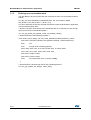
UM1686
User manual
BlueNRG development kits
Introduction
This document describes the BlueNRG development kits and related hardware and
software components. The BlueNRG is a very low power Bluetooth® low energy (BLE)
single-mode network processor, compliant with Bluetooth specifications core 4.0. The
BlueNRG can act as master or slave.
There are two types of BlueNRG kits:
1.
BlueNRG development platform (order code: STEVAL-IDB002V1)
2.
BlueNRG USB dongle (order code: STEVAL-IDB003V1)
The BlueNRG software package includes a graphical user interface application to control
the BlueNRG through a simple ACI protocol.
December 2014
DocID025464 Rev 3
1/47
www.st.com
Contents
UM1686
Contents
1
2
Getting started . . . . . . . . . . . . . . . . . . . . . . . . . . . . . . . . . . . . . . . . . . . . . . 4
1.1
STEVAL-IDB002V1 kit contents . . . . . . . . . . . . . . . . . . . . . . . . . . . . . . . . . 4
1.2
STEVAL-IDB003V1 kit . . . . . . . . . . . . . . . . . . . . . . . . . . . . . . . . . . . . . . . . 5
1.3
System requirements . . . . . . . . . . . . . . . . . . . . . . . . . . . . . . . . . . . . . . . . . 5
1.4
BlueNRG development kit setup . . . . . . . . . . . . . . . . . . . . . . . . . . . . . . . . 5
Hardware description . . . . . . . . . . . . . . . . . . . . . . . . . . . . . . . . . . . . . . . . 6
2.1
2.2
2.3
3
2/47
STEVAL-IDB002V1 motherboard . . . . . . . . . . . . . . . . . . . . . . . . . . . . . . . . 6
2.1.1
Microcontroller and connections . . . . . . . . . . . . . . . . . . . . . . . . . . . . . . . 7
2.1.2
Power . . . . . . . . . . . . . . . . . . . . . . . . . . . . . . . . . . . . . . . . . . . . . . . . . . . . 9
2.1.3
Sensors . . . . . . . . . . . . . . . . . . . . . . . . . . . . . . . . . . . . . . . . . . . . . . . . . 10
2.1.4
Extension connector . . . . . . . . . . . . . . . . . . . . . . . . . . . . . . . . . . . . . . . 10
2.1.5
Push-buttons and joystick . . . . . . . . . . . . . . . . . . . . . . . . . . . . . . . . . . . 10
2.1.6
JTAG connector . . . . . . . . . . . . . . . . . . . . . . . . . . . . . . . . . . . . . . . . . . . 10
2.1.7
LEDs . . . . . . . . . . . . . . . . . . . . . . . . . . . . . . . . . . . . . . . . . . . . . . . . . . . 10
2.1.8
Daughterboard interface . . . . . . . . . . . . . . . . . . . . . . . . . . . . . . . . . . . . 10
BlueNRG daughterboard . . . . . . . . . . . . . . . . . . . . . . . . . . . . . . . . . . . . . .11
2.2.1
Current measurements . . . . . . . . . . . . . . . . . . . . . . . . . . . . . . . . . . . . . 12
2.2.2
Hardware setup . . . . . . . . . . . . . . . . . . . . . . . . . . . . . . . . . . . . . . . . . . . 12
2.2.3
STM32L preprogrammed application . . . . . . . . . . . . . . . . . . . . . . . . . . 13
STEVAL-IDB003V1 USB dongle . . . . . . . . . . . . . . . . . . . . . . . . . . . . . . . 13
2.3.1
Microcontroller and connections . . . . . . . . . . . . . . . . . . . . . . . . . . . . . . 13
2.3.2
SWD interface . . . . . . . . . . . . . . . . . . . . . . . . . . . . . . . . . . . . . . . . . . . . 15
2.3.3
RF connector . . . . . . . . . . . . . . . . . . . . . . . . . . . . . . . . . . . . . . . . . . . . . 16
2.3.4
Push-buttons . . . . . . . . . . . . . . . . . . . . . . . . . . . . . . . . . . . . . . . . . . . . . 17
2.3.5
User LEDs . . . . . . . . . . . . . . . . . . . . . . . . . . . . . . . . . . . . . . . . . . . . . . . 17
2.3.6
Hardware setup . . . . . . . . . . . . . . . . . . . . . . . . . . . . . . . . . . . . . . . . . . . 17
2.3.7
STM32L preprogrammed application . . . . . . . . . . . . . . . . . . . . . . . . . . 17
GUI software description . . . . . . . . . . . . . . . . . . . . . . . . . . . . . . . . . . . . 18
3.1
Requirements . . . . . . . . . . . . . . . . . . . . . . . . . . . . . . . . . . . . . . . . . . . . . . 18
3.2
The BlueNRG graphical user interface . . . . . . . . . . . . . . . . . . . . . . . . . . . 18
3.2.1
GUI main window . . . . . . . . . . . . . . . . . . . . . . . . . . . . . . . . . . . . . . . . . . 19
3.2.2
Tools . . . . . . . . . . . . . . . . . . . . . . . . . . . . . . . . . . . . . . . . . . . . . . . . . . . 21
DocID025464 Rev 3
UM1686
4
5
6
7
Contents
3.2.3
GUI scripts window . . . . . . . . . . . . . . . . . . . . . . . . . . . . . . . . . . . . . . . . 23
3.2.4
GUI Beacon window . . . . . . . . . . . . . . . . . . . . . . . . . . . . . . . . . . . . . . . 28
Programming with BlueNRG network processor . . . . . . . . . . . . . . . . . 30
4.1
Requirements . . . . . . . . . . . . . . . . . . . . . . . . . . . . . . . . . . . . . . . . . . . . . . 30
4.2
Software directory structure . . . . . . . . . . . . . . . . . . . . . . . . . . . . . . . . . . . 30
BlueNRG sensor profile demo . . . . . . . . . . . . . . . . . . . . . . . . . . . . . . . . 32
5.1
Supported platforms . . . . . . . . . . . . . . . . . . . . . . . . . . . . . . . . . . . . . . . . . 33
5.2
BlueNRG app for smartphones . . . . . . . . . . . . . . . . . . . . . . . . . . . . . . . . 33
5.3
BlueNRG sensor profile demo: connection with a central device . . . . . . . 34
5.3.1
Initialization . . . . . . . . . . . . . . . . . . . . . . . . . . . . . . . . . . . . . . . . . . . . . . 34
5.3.2
Add service and characteristics . . . . . . . . . . . . . . . . . . . . . . . . . . . . . . . 34
5.3.3
Set security requirements . . . . . . . . . . . . . . . . . . . . . . . . . . . . . . . . . . . 35
5.3.4
Enter connectable mode . . . . . . . . . . . . . . . . . . . . . . . . . . . . . . . . . . . . 35
5.3.5
Connection with central device . . . . . . . . . . . . . . . . . . . . . . . . . . . . . . . 35
BlueNRG chat demo application . . . . . . . . . . . . . . . . . . . . . . . . . . . . . . 37
6.1
Supported platforms . . . . . . . . . . . . . . . . . . . . . . . . . . . . . . . . . . . . . . . . . 37
6.2
BlueNRG chat demo application: peripheral & central devices . . . . . . . . 37
6.2.1
Initialization . . . . . . . . . . . . . . . . . . . . . . . . . . . . . . . . . . . . . . . . . . . . . . 38
6.2.2
Add service and characteristics . . . . . . . . . . . . . . . . . . . . . . . . . . . . . . . 38
6.2.3
Set security requirements . . . . . . . . . . . . . . . . . . . . . . . . . . . . . . . . . . . 38
6.2.4
Enter connectable mode . . . . . . . . . . . . . . . . . . . . . . . . . . . . . . . . . . . . 39
6.2.5
Connection with central device . . . . . . . . . . . . . . . . . . . . . . . . . . . . . . . 39
BlueNRG Beacon demonstration application . . . . . . . . . . . . . . . . . . . . 41
7.1
Supported platforms . . . . . . . . . . . . . . . . . . . . . . . . . . . . . . . . . . . . . . . . . 41
7.1.1
Initialization . . . . . . . . . . . . . . . . . . . . . . . . . . . . . . . . . . . . . . . . . . . . . . 41
7.1.2
Define advertising data . . . . . . . . . . . . . . . . . . . . . . . . . . . . . . . . . . . . . 41
7.1.3
Entering non-connectable mode . . . . . . . . . . . . . . . . . . . . . . . . . . . . . . 42
8
List of acronyms . . . . . . . . . . . . . . . . . . . . . . . . . . . . . . . . . . . . . . . . . . . 43
9
Available board schematics . . . . . . . . . . . . . . . . . . . . . . . . . . . . . . . . . . 44
10
Revision history . . . . . . . . . . . . . . . . . . . . . . . . . . . . . . . . . . . . . . . . . . . 46
DocID025464 Rev 3
3/47
47
Getting started
1
UM1686
Getting started
This section describes all the software and hardware requirements for running the BlueNRG
GUI utility as well as the related installation procedure.
1.1
STEVAL-IDB002V1 kit contents
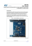
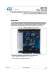
This kit is composed of the following items:
•
1 development motherboard
•
1 BlueNRG daughterboard
•
1 2.4 GHz Bluetooth antenna
•
1 USB cable
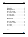
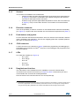
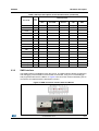
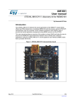
Figure 1. BlueNRG kit motherboard with daughterboard connected
(STEVAL-IDB002V1)
4/47
DocID025464 Rev 3
UM1686
1.2
Getting started
STEVAL-IDB003V1 kit
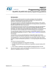
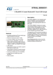
This kit is composed of the following items:
•
1 USB dongle
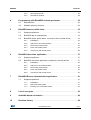
Figure 2. STEVAL-IDB003V1 BlueNRG USB dongle
1.3
System requirements
The BlueNRG graphical user interface utility has the following minimum requirements:
•
1.4
Note:
PC with Intel® or AMD® processor running one of the following Microsoft® operating
systems:
–
Windows XP SP3
–
Windows Vista
–
Windows 7
•
At least 128 Mb of RAM
•
2 USB ports
•
40 Mb of hard disk space available
•
Adobe Acrobat Reader 6.0 or later.
BlueNRG development kit setup
•
Extract the content of the BlueNRG_DK_-x.x.x-Setup.zip file into a temporary directory.
•
Launch the BlueNRG-DK-x.x.x-Setup.exe file and follow the on-screen instructions.
EWARM Compiler 6.60 version is required for building the BlueNRG_DK_x.x.x
demonstration applications.
DocID025464 Rev 3
5/47
47
Hardware description
2
UM1686
Hardware description
The following sections describe the components of the kits.
2.1
STEVAL-IDB002V1 motherboard
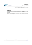
The motherboard included in the development kit allows testing of the functionality of the
BlueNRG processor. The board can be used as a simple interface between the BlueNRG
and a GUI application on the PC. The STM32L microcontroller on the board can also be
programmed, so the board can be used to develop applications using the BlueNRG. A
connector on the motherboard (Figure 1) allows access to the JTAG interface for
programming and debugging. The board can be powered through a mini-USB connector
that can also be used for I/O interaction with a USB Host. The board includes sensors, and
buttons and a joystick for user interaction. The RF daughterboard can be easily connected
through a dedicated interface.
This is a list of some of the features that are available on the boards:
6/47
•
STM32L151RBT6 64-pin microcontroller
•
Mini USB connector for power supply and I/O
•
JTAG connector
•
RF daughterboard interface
•
One RESET button and one USER button
•
One LIS3DH accelerometer
•
One STLM75 temperature sensor
•
One joystick
•
5 LEDs
•
One PWR LED
•
One battery holder for 2 AAA batteries
•
One row of test points on the interface to the RF daughterboard
DocID025464 Rev 3
UM1686
Hardware description
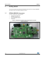
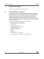
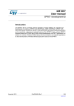
Figure 3. Motherboard for the BlueNRG development kit
2.1.1
Microcontroller and connections
The board features an STM32L151RB microcontroller, which is an ultra low-power
microcontroller with 128 KB of Flash memory, 16 KB of RAM, 32-bit core ARM cortex-M3, 4
KB of data EEPROM, RTC, LCD, timers, USART, I2C, SPI, ADC, DAC and comparators.
The microcontroller is connected to various components such as buttons, LEDs and
connectors for external circuitry. The following table shows what functionality is available on
each microcontroller pin.
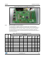
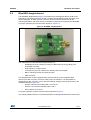
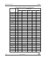
Table 1. MCU pin description versus board function
Board function
Pin
name
Pin
VLCD
1
PC13
2
PC14
3
3
PC15
4
5
OSC_IN
5
OSC_OU
T
6
NRST
7
PC0
8
LED1
PC1
9
LED2
PC2
10
PC3
11
LEDs
DB connector
Buttons /
joystick
Acceler.
Temperature
sensor
USB
JTAG
Ext.
conn
DB_SDN_RST
RESET
7
DB_PIN3
9
DocID025464 Rev 3
7/47
47
Hardware description
UM1686
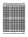
Table 1. MCU pin description versus board function (continued)
Board function
Pin
name
Pin
VSSA
12
VDDA
13
PA0
14
11
PA1
15
13
PA2
16
15
PA3
17
17
VSS_4
18
VDD_4
19
PA4
20
SPI1_NSS
PA5
21
SPI1_SCK
PA6
22
SPI1_MISO
PA7
23
SPI1_MOSI
PC4
24
LED4
PC5
25
LED5
PB0
26
JOY_DOW
N
PB1
27
JOY_RIGH
T
PB2
28
PB10
29
INT1
PB11
30
INT2
VSS_1
31
VDD_1
32
PB12
33
DB_CSN(1)
PB13
34
DB_SCLK(1)
PB14
35
DB_SDO(1)
PB15
36
DB_SDI(1)
PC6
37
PC7
38
DB_IO0(1)
PC8
39
DB_IO1(1)
PC9
40
DB_IO2(1)
PA8
41
JOY_LEFT
PA9
42
JOY_CENT
ER
PA10
43
JOY_UP
8/47
LEDs
DB connector
Buttons /
joystick
Acceler.
Temperature
sensor
USB
JTAG
Ext.
conn
18
PUSH_BTN
DocID025464 Rev 3
UM1686
Hardware description
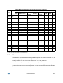
Table 1. MCU pin description versus board function (continued)
Board function
Pin
name
Pin
PA11
44
USB_D
M
PA12
45
USB_D
P
PA13
46
VSS_2
47
VDD_2
48
PA14
49
PA15
50
LEDs
Buttons /
joystick
DB connector
DB_IO3_IRQ
Acceler.
Temperature
sensor
USB
JTAG
Ext.
conn
JTMS
16
JTCK
14
JTDI
12
(1)
PC10
51
PC11
52
DB_PIN1
PC12
53
DB_PIN2
PD2
54
PB3
55
JTDO
10
PB4
56
JNTRST
8
PB5
57
TSEN_INT
PB6
58
I2C1_SCL
PB7
59
I2C1_SDA
BOOT0
60
PB8
61
4
PB9
62
6
VSS_3
63
VDD_3
64
LED3
1. These lines are also available on the test point row
2.1.2
Power
The board can be powered either by the mini USB connector CN1 (A in Figure 3) or by 2
AAA batteries. To power the board through USB bus, jumper JP1 must be in position 1-2, as
in Figure 3 (B). To power the board using batteries, 2 AAA batteries must be inserted in the
battery holder at the rear of the board, and jumper JP1 set to position 2-3.
When the board is powered, the green LED DL6 is on (C).
If needed, the board can be powered by an external DC power supply. Connect the positive
output of the power supply to the central pin of JP1 (pin 2) and ground to one of the four test
point connectors on the motherboard (TP1, TP2, TP3 and TP4).
DocID025464 Rev 3
9/47
47
Hardware description
2.1.3
UM1686
Sensors
Two sensors are available on the motherboard:
2.1.4
–
LIS3DH, an ultra-low power high performance three-axis linear accelerometer (D
in Figure 3). The sensor is connected to the STM32L through the SPI interface.
Two lines for interrupts are also connected.
–
STLM75, a high precision digital CMOS temperature sensor, with I2C interface (E
in Figure 3). The pin for the alarm function is connected to one of the STM32L
GPIOs.
Extension connector
There is the possibility to solder a connector on the motherboard to extend its functionality
(F in Figure 3). 16 pins of the microcontroller are connected to this expansion slot (Table 1).
2.1.5
Push-buttons and joystick
For user interaction the board has two buttons. One is to reset the microcontroller, while the
other is available to the application. There is also a digital joystick with 4 possible positions
(left, right, up, down) (G in Figure 3).
2.1.6
JTAG connector
A JTAG connector on the board (H in Figure 3) allows the programming and debugging of
the STM32L microcontroller on board(a), using an in-circuit debugger and programmer such
as the ST-LINK/V2.
2.1.7
LEDs
Five LEDs are available (I in Figure 3).
2.1.8
–
DL1: green
–
DL2: orange
–
DL3: red
–
DL4: blue
–
DL5: yellow
Daughterboard interface
The main feature of the motherboard is the capability to control an external board,
connected to the J4 and J5 connectors (L in Figure 3). Table 1 shows which pins of the
microcontroller are connected to the daughterboard.
Some of the lines are connected also to a row of test points (M).
a. The STM32L is preprogrammed with a DFU firmware that allows the downloading of a firmware image without
the use of a programmer. If an user accidentally erases DFU firmware, he can reprogram it through STLink
using the hex image DFU_Bootloader.hex available on BlueNRG DK SW package, firmware folder.
10/47
DocID025464 Rev 3
UM1686
2.2
Hardware description
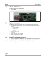
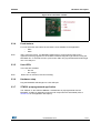
BlueNRG daughterboard
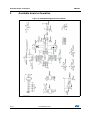
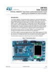
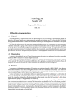
The BlueNRG daughterboard (Figure 4) included in the development kit is a small circuit
board to be connected to the main board. It contains the BlueNRG network processor (in a
QFN32 package), an SMA antenna connector, discrete passive components for RF
matching and balun, and small number of additional components required by the BlueNRG
for proper operation (see the schematic diagram in Figure 21).
Figure 4. BlueNRG daughterboard
The main features of the BlueNRG daughterboard are:
–
BlueNRG low power network processor for Bluetooth low energy (BLE), with
embedded host stack
–
High frequency 16 MHz crystal
–
Low frequency 32 kHz crystal for the lowest power consumption
–
Balun, matching network and harmonic filter
–
SMA connector
The daughterboard is also equipped with a discrete inductor for the integrated highefficiency DC-DC converter, for best-in-class power consumption. It is still possible to
disable the DC-DC converter. In this case the following changes must be performed on the
daughterboard (see Figure 21):
–
Remove inductor from solder pads 1 and 2 of D1
–
Place a 0 ohm resistor between pads 1 and 3
–
Move resistor on R2 to R1
For proper operation, jumpers must be set as indicated in Figure 4.
The following tables show the connections between the daughterboard and the main board.
DocID025464 Rev 3
11/47
47
Hardware description
UM1686
Table 2. Connections between BlueNRG board and motherboard on left connector
Pin
J4 motherboard
J3 daughterboard
1
DB_PIN1
NC
2
3V3
3V3
3
DB_PIN3
NC
4
NC
NC
5
GND
GND
6
DB_PIN2
nS
7
GND
GND
8
3V3
U2 pin 1
9
DB_SDN_RST
RST
10
3V3
U2 pin 1
Table 3. Connections between BlueNRG board and motherboard on right connector
2.2.1
Pin
J5 motherboard
J4 daughterboard
1
GND
GND
2
GND
GND
3
DB_CSN
CSN
4
DB_IO3_IRQ
IRQ
5
DB_SCLK
CLK
6
DB_IO2
NC
7
DB_SDI
MOSI
8
DB_IO1
NC
9
DB_SDO
MISO
10
DB_IO0
NC
Current measurements
To monitor power consumption of the entire BlueNRG daughterboard, remove the jumper
from U2 and insert an ammeter between pins 1 and 2 of the connector. Since power
consumption of the BlueNRG during most operation time is very low, an accurate instrument
in the range of few microamps may be required.
2.2.2
12/47
Hardware setup
1.
Plug the BlueNRG daughterboard into J4 and J5 connectors as in Figure 1.
2.
Ensure the jumper configuration on the daughterboard is as in Figure 1
3.
Connect the motherboard to the PC with an USB cable (through connector CN1).
4.
Verify the PWR LED lights is on.
DocID025464 Rev 3
UM1686
2.2.3
Hardware description
STM32L preprogrammed application
The STM32L on STEVAL-IDB002V1 motherboard is preprogrammed with the sensor demo
application when the kits components are assembled (refer to Section 5 for the application
description).
2.3
STEVAL-IDB003V1 USB dongle
The BlueNRG USB dongle allows users to easily add BLE functionalities to their PC by
plugging it into a USB port. The USB dongle can be used as a simple interface between the
BlueNRG and a GUI application on the PC. The on-board STM32L microcontroller can also
be programmed, so the board can be used to develop applications that use the BlueNRG.
The board can be powered through the USB connector, which can also be used for I/O
interaction with a USB host. The board also has two buttons and two LEDs for user
interaction.
Below is a list of some of the main features that are available on the board (see Figure 2):
2.3.1
•
BlueNRG network coprocessor
•
STM32L151CBU6 48-pin microcontroller
•
USB connector for power supply and I/O
•
One row of pins with SWD interface
•
Chip antenna
•
Two user buttons (SW1, SW2)
•
Two LEDs (D2, D3)
Microcontroller and connections
The board utilizes an STM32L151CBU6, which is an ultra low-power microcontroller with
128 KB of Flash memory, 16 KB of RAM, 32-bit core ARM cortex-M3, 4 KB of data
EEPROM, RTC, timers, USART, I2C, SPI, ADC, DAC and comparators.
The microcontroller is connected to various components such as buttons, LEDs and
connectors for external circuitry. The following table shows which functionality is available
on each microcontroller pin.
DocID025464 Rev 3
13/47
47
Hardware description
UM1686
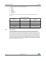
Table 4. MCU pin description versus board function
Board function
Pin name
14/47
Pin
num.
LEDs
BlueNRG
VLCD
1
PC13
2
PC14
3
PC15
4
OSC_IN
5
OSC_OUT
6
NRST
7
VSS_A
8
VDD_A
9
PA0
10
PA1
11
PA2
12
PA3
13
PA4
14
PA5
15
PA6
16
PA7
17
PB0
18
Led D2
PB1
19
Led D3
PB2
20
PB10
21
PB11
22
VSS1
23
VDD1
24
PB12
25
SPI2_CS
PB13
26
SPI2_CLK
PB14
27
SPI2_MISO
PB15
28
SPI2_MOSI
PA8
29
PA9
30
PA10
31
PA11
32
Buttons
USB
VBAT
Button SW2
Button SW1
BlueNRG_IRQ
EEPROM_CS
USB_DM
DocID025464 Rev 3
SWD
UM1686
Hardware description
Table 4. MCU pin description versus board function (continued)
Board function
Pin name
Pin
num.
LEDs
2.3.2
PA12
33
PA13
34
VSS2
35
VDD2
36
PA14
37
PA15
38
PB3
39
PB4
40
PB5
41
PB6
42
PB7
43
BOOT0
44
PB8
45
PB9
46
VSS_3
47
VDD_4
48
BlueNRG
Buttons
USB
SWD
USB_DP
SWDIO
SWCLK
SWO
SWD interface
The SWD interface is available through the J2 pins. The SWD interface allows programming
and debugging of the STM32L microcontroller on the board, using an in-circuit debugger
and programmer like the ST-LINK/V2. In Figure 5 the connection scheme illustrating how to
connect the ST-LINK/V2 with the board pins is shown.
Figure 5. SWD connection scheme with ST-LINK/V2
DocID025464 Rev 3
15/47
47
Hardware description
UM1686
The signals available on the STEVAL-IDB003V1 are:
1.
GND
2.
VDD
3.
nRESET
4.
SWDIO
5.
SWO/TRACE
6.
SWCLK
The connection to the ST-LINK/V2 interface is given in the table below, as shown in
Figure 5:
Table 5. SWD connection
STEVAL-IDS001Vx
ST-LINK/V2
pin number
pin number
GND
1
14 /6
VDD
2
2/1
nRESET
3
15
SWDIO
4
7
SWO/TRACE
5
13
SWCLK
6
9
Signal name
2.3.3
RF connector
The STEVAL-IDB003V1 provides two different RF connections: antenna (chip antenna,
default configuration) and UFL connector. Although the default configuration allows
communication on air, it can be useful to switch to the UFL connector in order to connect the
STEVAL-IDB003V1 to RF equipment such as a spectrum analyzer or RF signal generator.
To switch from antenna to UFL connector, capacitor C10 must be removed and capacitor
C42 must be soldered. To restore the default configuration and use the antenna, capacitor
C42 must be removed and capacitor C10 must be soldered. Both capacitors C10 and C42
have the same value: 56 pF. In Figure 6, the two pads for C10 and C42 are shown together
with the chip antenna and UFL connector.
16/47
DocID025464 Rev 3
UM1686
Hardware description
Figure 6. RF connector scheme
2.3.4
Push-buttons
For user interaction the board has two buttons, both available to the application
–
SW1
–
SW2
Note:
SW1 is the DFU button. The BlueNRG USB dongle is preprogrammed with a DFU
application allowing upgrades to the STM32L firmware image through USB and using the
BlueNRG GUI. To activate the DFU, press button SW1 and plug the BlueNRG USB dongle
into a PC USB port.
2.3.5
User LEDs
Two LEDs are available:
–
D2: red
–
D3: orange
Note:
When DFU is activated, LED D3 is blinking
2.3.6
Hardware setup
Plug the BlueNRG USB dongle into a PC USB port.
2.3.7
STM32L preprogrammed application
The STM32L on the STEVAL-IDB003V1 motherboard is preprogrammed with the
BlueNRG_VCOM.hex application when the kits components are assembled (refer to
Section 3.1 for the application description).
DocID025464 Rev 3
17/47
47
GUI software description
3
UM1686
GUI software description
The BlueNRG GUI included in the software package is a graphical user interface that can be
used to interact and evaluate the capabilities of the BlueNRG network processor.
This utility can send standard and vendor-specific HCI commands to the controller and
receive events from it. It lets the user configure each field of the HCI command packets to
be sent and analyzes all received packets. In this way BlueNRG can be easily managed at
low level.
3.1
Requirements
In order to use the BlueNRG GUI, make sure you have correctly set up your hardware and
software (BlueNRG GUI installed). The STM32L in the STEVAL-IDB002V1 kit has been
preprogrammed with a demo application (see Section 5). Hence, new firmware must be
loaded into the STM32L. Firmware images can be found within the firmware folder. The
firmware image that must be programmed is BlueNRG_VCOM.hex. The GUI has the ability
to Flash new firmware.
In order to download binary images into the internal Flash of the STM32L, the
microcontroller must be put into a special DFU (device firmware upgrade) mode. To enter
DFU mode:
1.
2.
3.2
BlueNRG development platform (STEVAL-IDB002V1)
–
Power up the board
–
Press and hold USER button
–
Reset the board using RESET button (keep USER button pressed while resetting)
The orange LED DL2 will start to blink
–
Release USER button
–
Use BlueNRG GUI to Flash the device with new firmware (Tools -> Flash
motherboard FW).
BlueNRG USB Dongle (order code: STEVAL-IDB003V1)
–
Press and hold SW1 button
–
Plug the USB dongle on a PC USB port. The orange LED D3 will start to blink.
–
Use BlueNRG GUI to Flash the device with a new firmware (Tools -> Flash
Motherboard FW).
The BlueNRG graphical user interface
This section describes the main functions of BlueNRG GUI application.
You can run this utility by clicking on the BlueNRG GUI icon on the Desktop or under:
Start → STMicroelectronics → BlueNRG DK X.X.X → BlueNRG GUI
18/47
DocID025464 Rev 3
UM1686
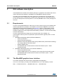
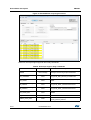
3.2.1
GUI software description
GUI main window
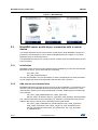
Figure 7. BlueNRG GUI main window
The BlueNRG GUI main window is characterized by different zones. Some of these zones
can be resized.
Port and interface selection
The uppermost zone allows the user to open the COM port associated to the BTLE
controller.
When a COM port is opened the following information are displayed:
– BlueNRG HW version
– BlueNRG FW version
– STM32L motherboard GUI firmware (VCOM) version
HCI commands
The HCI Commands tab contains a list of all the available HCI commands. Commands can
be filtered by checking/unchecking boxes under the filter section. After clicking on one of the
commands, all the packet fields will be displayed on the command packet table in the upperright section of the tab (see Figure 8).
DocID025464 Rev 3
19/47
47
GUI software description
UM1686
Figure 8. Command packet table
The command packet table contains four columns:
•
Parameter: name of the packet field as they are named in volume 2, part E of
Bluetooth specification.
•
Value: field value represented in hexadecimal format (right-click on a cell to change its
representation format).
•
Literal: meaning of the current field value.
•
Info: description of the corresponding field.
Only the yellow cells of this table can be modified by the user. The Parameter Total Length is
fixed or automatically calculated after modifying cell content.
After the fields have been modified (if required) the command can be sent using the Send
button.
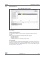
HCI Packet history and details
At the bottom of the main window, two tables show packets sent to and received from the
BTLE controller, as well as other events. The left table (sent/received packets) holds a
history of all packets (see Figure 9). The right one (packet details) shows all the details of
the selected packet as is done in the command packet table (Figure 9).
Figure 9. Packet history and details
Double-clicking on a row of the sent/received packets table shows the raw packet.
20/47
DocID025464 Rev 3
UM1686
GUI software description
Figure 10. Raw packet dump
Some events (displayed in yellow cells) can provide other information. HCI packets sent
towards the BTLE controller are displayed in gray cells while received packets are shown
inside white cells.
The Sent/received packets table can be cleared by clicking on clear list button. Update and
auto-scrolling check boxes enable or disable updating and auto-scrolling of the
Sent/received packets table while new packets are sent or received (however, information
will still be printed).
3.2.2
Tools
The BlueNRG GUI has some functions that can be accessed through the tools menu. These
tools are described in this section.
BlueNRG updater
This tool can be used to update the firmware inside the BlueNRG by using its internal
bootloader. VCOM firmware must be present on the STM32L and COM port must be open,
in order to use this function.
1.
Go to Tools -> BlueNGR updater
2.
Select the correct stack firmware (.img)
3.
Press update to start the update procedure. If the procedure completes with no errors,
the new firmware has been loaded into the BlueNRG internal Flash.
BlueNRG IFR
To preserve BlueNRG’s flexibility, its firmware uses a table of configurable parameters. This
table resides in a sector of the Flash(b) (IFR). BlueNRG IFR Tool can read and modify this
portion of BlueNRG’s Flash.
b. In special cases, a new BlueNRG BLE stack may require a new bootloader. In such cases, a special firmware
must be loaded before flashing the new stack. Refer to that particular firmware documentation for more info.
DocID025464 Rev 3
21/47
47
GUI software description
UM1686
Figure 11. BlueNRG GUI IFR tool
This tool allows to:
•
Load a configuration file.
•
Save the parameters into a configuration files.
•
Change stack mode. Each mode has a different functionality:
–
Mode 1: slave/master, 1 connection only, small GATT database (RAM2 off during
sleep)
–
Mode 2: slave/master, 1 connection only, large GATT database (RAM2 on during
sleep)
–
Mode 3: slave/master, 8 connections, small GATT database (RAM2 on during
sleep)
•
Change HS startup time parameter. This parameter control the time offset between the
wake-up of the device and the start of RX/TX phase. Must be big enough to let the
device be ready to transmit or receive after wake up from sleep. This time depends on
the startup time of the high speed crystal.
•
Change sleep clock accuracy. It must reflect the actual clock accuracy, depending on
the low speed oscillator or crystal in use.
•
View registers that are written into the radio.
•
View/change date to distinguish different versions of configurations.
•
Read IFR content from BlueNRG.
•
Write configuration into BlueNRG IFR.
Flash motherboard firmware
The BlueNRG GUI embeds an utility that allows to Flash a firmware into the STM32L
microcontroller on the motherboard without a JTAG/SWD programmer. This utility uses a
bootloader that has been programmed in the first 12 KB of the Flash. Any application that
wants to be programmed into the STM32L by this tool, must consider that the lower area of
the Flash is used by the bootloader(c).
c. Two precautions must be taken for any firmware: 1) change memory regions in linker script (vector table and
Flash must start at 0x08003000); 2) Change the vector table offset (NVIC_SetVectorTable())
22/47
DocID025464 Rev 3
UM1686
GUI software description
OTA bootloader
OTA bootloader is a tool that allows to Flash new firmware into the STM32L of a remote
device via Bluetooth low energy technology. Refer to the dedicated application note for
more information.
Get production data
From tools menu there is the possibility to retrieve production information from the BlueNRG
daughterboard. This data is stored inside the EEPROM on the daughterboard.
Get version
The Get version tool is used to retrieve the version of the BlueNRG GUI firmware (VCOM)
on the STM23L, and hardware and firmware version from the BlueNRG.
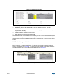
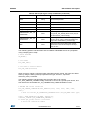
3.2.3
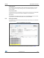
GUI scripts window
The BlueNRG GUI scripts window provides several tabs to allow testing of some BlueNRG
application scenarios.
Figure 12. BlueNRG GUI scripts window
Master and Slave roles are supported with the BLE operations described in Table 6.
DocID025464 Rev 3
23/47
47
GUI software description
UM1686
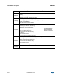
Table 6. GUI scripts window: available master operations
Operation
Initialization
Scanning
Connection
Associated actions
Allows to initialize a BlueNRG device as Central, by
selecting:
- Stack Mode (1,2,3);
- Address type (Public, Random) and value
Allows to put device in scanning mode by selecting:
- Scanning type (Limited or General Discovery procedure)
- Enable or Disable filters
- Set Scanning interval and Window
Allows to connect to a peer device by:
- Searching for devices in Advertising
- Select the device to which to connect
- Select the connection parameters
- Peer address and type
- Scan Interval and Window
- Connection Interval (min & max)
- Latency
- Supervision timeout
- Connection event length (min & max)
Allows to update the current connection parameters by
- Selecting the specific connection to be updated
- Set the new connection parameters
Update
- Connection interval (Min & Max)
Connections
- Latency
- Supervision timeout
- Connection event length (min & max)
Terminate
Connection
24/47
Notes
Allows to terminate the current connection
DocID025464 Rev 3
The addresses of the
detected advertising
devices are displayed
UM1686
GUI software description
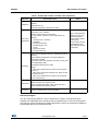
Table 7. GUI Scripts window: available slave operations
Operation
Associated actions
Initialization
Allows to initialize a BlueNRG device as a peripheral, by
selecting:
- Stack Mode (1,2);
- Address type (Public, Random) and value
Service and
Characteristi
cs…
Allows to add a service by selecting:
- UUID type (16 or 128 bits)
- Service Type (Primary or Secondary)
For each service, it allows to add a characteristic by
selecting
- UUID type (16 or 128 bits)
- Properties
- Security permissions
- Variable length or not
- Length
- GATT Event mask
- Encryption key size
Advertising
Allows to put a Peripheral device in Advertising mode by
selecting:
- Discoverable mode (limited, non discoverable and
general discoverable)
- Type (ADV_IND, ADV_DIRECT_IND, ADV_SCAN_IND,
ADV_NONCONN_IND)
- Advertising intervals (min & max)
- Policy:
- Allow scan request from any, allow connect request
from any
- Allow scan request from white list only, allow connect request from any
- Allow scan request from any, allow connect request
from white list only
Update Data
Allows to update the advertising data;
Allows to set the scan response data;
Allows to update the location UUID, major and minor
number defined in the Beacon window
Terminate
Connection
It allows to terminate the current connection
Notes
After a characteristic is
defined, the user can
edit its parameters
and/or delete it before
selecting OK.
Once a service and its
characteristics have
been defined, click OK
to add them.
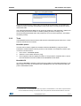
GUI script engine
The GUI script engine allows the user to load and run a python script built using the
available set of BlueNRG ACI commands and the related events. For the list of supported
HCI and ACI scripts commands and related parameters, refer to the commands available in
the BlueNRG GUI ACI Commands window.
DocID025464 Rev 3
25/47
47
GUI software description
UM1686
Figure 13. BlueNRG GUI script engine section
Moreover, the script engine supports other utility commands:
Table 8. GUI script engine: utility commands
Command name
ERROR
26/47
Parameters
User message
Description
Raises an exception with a user-defined debug
message. The running script is terminated.
GET_ADDRESS
None
Returns the address within the
EVT_BLUE_GAP_DEVICE_FOUND event
GET_NAME
None
Returns the device name within an advertising
packet
GET_NOTIFICATION_CH
AR_HANDLE
None
Returns the characteristic handle of the received
EVT_BLUE_GATT_NOTIFICATION event
GET_NOTIFICATION_CO
NN_HANDLE
None
Returns the connection handle of the received
EVT_BLUE_GATT_NOTIFICATION event
GET_RAND_KEY
None
Returns a random number between 0 and
999999
HW_RESET
Node
HW reset
INSERT_PASS_KEY
Node
Allows to enter a pass key value used for the
security pass key method
DocID025464 Rev 3
UM1686
GUI software description
Table 8. GUI script engine: utility commands (continued)
Command name
Parameters
Description
PRINT
String
Print utility: displays information on GUI
Sent/received packets
RESET
None
SW reset
SLEEP
Time
Sleeps for “time” seconds
SET_MODE
Mode
Set stack mode (1,2,3)
SET_PUBLIC_ADDRESS
Public address
Set public address (optional)
SENSORDEMO_GET_TE
MPERATURE
None
Allows to get the temperature value from the
EVT_BLUE_ATT_READ_RESP event (only for
the SensorDemo_Central script)
SENSORDEMO_GET_AC
CELERATION
None
Allows to get the acceleration values (x,y,z) from
the EVT_BLUE_GATT_NOTIFICATION event
(only for the SensorDemo_Central script)
TIME
None
Returns the time as a floating point number
expressed in seconds since epoch January 1,
1970, in UTC
The following pseudo code describes how to initialize a BlueNRG device as a peripheral
using a simple python script:
# Reset BlueNRG
HW_RESET()
# Init GATT
ACI_GATT_INIT()
# Init GAP as central device
ACI_GAP_INIT(Role=0x03)
When a script is calling a command which generates specific events, the script can detect
them by using the WAIT_EVENT(“expected event type, “timeout”, “expected
subevent_code”) command.
The following pseudo code describes how a master device can call the
ACI_GAP_CREATE_CONNECTION() command to connect to a specific peer device, and
then wait for the associated HCI_LE_CONNECTION_COMPLETE META event:
# MASTER GAP Create Connection
ACI_GAP_CREATE_CONNECTION(Peer_Address=[0x12, 0x34, 0x00, 0xE1, 0x80,
0x02])
# Wait for the HCI_LE_CONNECTION_COMPLETE event (HCI_LE_META event type)
event = WAIT_EVENT(HCI_LE_META, timeout=30,
Subevent_Code=HCI_LE_CONNECTION_COMPLETE )
if event.get_param('Status').val==0x00:
# Store the connection handle
DocID025464 Rev 3
27/47
47
GUI software description
UM1686
conn_handle= event.get_param('Connection_Handle').val
GUI script engine loading and running steps
To load and run a python script using the BlueNRG GUI script engine, the following steps
must be observed:
1.
In the BlueNRG GUI, Scripts window, Script Engine section, click on tab “…”, browse to
the script location and select the script
2.
Click on the “Run Script” tab to run the script. The execution flow (commands and
events) will be displayed in the BlueNRG GUI “Sent/Received Packets” section
In the BlueNRG DK 1.6.0 and future versions, some reference BlueNRG scripts are
available in the GUI/scripts folder.
Note:
It is worthy of note that in order to write and use the BlueNRG scripts, the user is required to
have some knowledge of the Python language (Python 2.7.6), and a good understanding of
the BlueNRG ACI commands and related events. For a detailed description of the BlueNRG
ACI commands and related events, refer to the BlueNRG Bluetooth LE stack application
command interface (ACI) user manual UM1755.
3.2.4
GUI Beacon window
The BlueNRG GUI Beacon window provides some tabs allowing configuration of a
BlueNRG device as a BLE Beacon device which transmits advertising packets with specific
manufacturer data.
Figure 14. BlueNRG GUI Beacon window
28/47
DocID025464 Rev 3
UM1686
GUI software description
The user can configure the following advertising data fields for the BLE Beacon device,
through the BlueNRG GUI Beacon window configuration parameters.
Table 9. BlueNRG GUI beacon window configuration parameters
Data field
Description
Address
Device address
Public or Random
Device address type
Company Identifier Code
SIG company identifier
Default is 0x0030 (STMicroelectronics)
ID
Beacon ID
Fixed value
Location UUID
Beacons UUID
Used to distinguish specific beacons
from others
Major number
Notes
Identifier for a group of beacons Used to group a related set of beacons
Minor number
Identifier for a single beacon
Used to identify a single beacon
Tx Power Level
2's complement of the Tx power
Used to establish how far you are from
device
To configure a BlueNRG platform as a BLE beacon device, click on “Set Beacon” tab.
DocID025464 Rev 3
29/47
47
Programming with BlueNRG network processor
4
UM1686
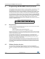
Programming with BlueNRG network processor
The BlueNRG provides a high level interface to control its operation. This interface is called
ACI (application-controller interface). The ACI is implemented as an extension to the
standard Bluetooth HCI interface. Since BlueNRG is a network processor, the stack runs
inside the device itself. Hence, no library is required on the external microcontroller, except
for profiles and all the functions needed to communicate with the BlueNRG SPI interface.
The development kit software includes sample code that shows how to configure BlueNRG
and send commands or parsing events. The source library is called simple BlueNRG HCI to
distinguish it from the library for the complete profile framework (not present in the software
development kit). This library is able to handle multiple profiles at the same time and
supports several Bluetooth GATT-based profiles for BlueNRG. Documentation on the ACI is
provided in a separate document.
Figure 15. Profile framework structure
Proximity
FindMe
HOGP
...
...
...
Basic profile framework
4.1
Requirements
In order to communicate with BlueNRG network processor very few resources are needed
by the main processor. These are listed below:
–
SPI interface
–
Platform-dependent code to write/read to/from SPI
–
A timer to handle SPI timeouts or to run Bluetooth LE Profiles
Minimum requirements in terms of Flash and RAM space largely depend on the functionality
needed by the application, on the microprocessor that will run the code and on the compiler
toolchain used to build the firmware.
On the STM32L (Cortex-M3 core), the memory footprint for the code interfacing the
BlueNRG requires few kilobytes of Flash and RAM (typically 2-4 KB of Flash, and 0.8-1.5
KB of RAM). So a complete simple application (like the BlueNRG sensor demo) could
require just 15 KB of Flash and 2 KB of RAM.
If using the complete BlueNRG profile framework, the memory footprint is around 9 KB of
code and 3 KB of data for just the ACI interface and the profile framework functions. The
memory required for the profiles can vary depending on the complexity of the profile itself.
For example, code for HID-over-GATT host is around 6 KB, while for heart rate monitor is
around 2.3 KB.
4.2
Software directory structure
The Project folder contains some sample code that can be used on the application
processor to control the BlueNRG. Platform-dependent code is also provided for STM32L1
platforms. The example project provided in the package will run “as is” on the development
kit.
30/47
DocID025464 Rev 3
UM1686
Programming with BlueNRG network processor
The files are organized using the following folder structure:
–
Bluetooth LE. Contains the code that is used to send ACI commands to the
BlueNRG network processor. It contains also definitions of BlueNRG events.
–
platform. Contains all the platform-dependent files. These can be taken as an
example to build applications that can be run on other platforms.
–
Project. Contains source code that can be used as an example to build other
applications that will use the Bluetooth technology with the BlueNRG. Project files
for IAR embedded workbench are also available.
DocID025464 Rev 3
31/47
47
BlueNRG sensor profile demo
5
UM1686
BlueNRG sensor profile demo
The software development kit contains an example, which implements a proprietary
Bluetooth profile: the sensor profile. This example is useful for building new profiles and
applications that use the BlueNRG network processor. This GATT profile is not compliant to
any existing specification. The purpose of this project is simply to show how to implement a
given profile.
This profile exposes two services: acceleration service and environmental service.
Figure 16 shows the whole GATT database, including the GATT and GAP services that are
automatically added by the stack.
One of the acceleration service’s characteristics has been called free-fall characteristic. This
characteristic cannot be read or written but can be notified. The application will send a
notification on this characteristic (with value equal to 0x01) if a free-fall condition has been
detected by the LIS3DH MEMS sensor (the condition is detected if the acceleration on the 3
axes is near zero for a certain amount of time). Notifications can be enabled or disabled by
writing on the related client characteristic configuration descriptor.
The other characteristic exposed by the service gives the current value of the acceleration
that is measured by the accelerometer. The value is made up of six bytes. Each couple of
bytes contains the acceleration on one of the 3 axes. The values are given in mg. This
characteristic is readable and can be notified if notifications are enabled.
Another service is also defined. This service contains characteristics that expose data from
some environmental sensors: temperature, pressure and humidity(d). For each
characteristic, a characteristic format descriptor is present to describe the type of data
contained inside the characteristic. All of the characteristics have read-only properties
d. An expansion board with LPS25H pressure sensor and HTS221 humidity sensor can be connected to the
motherboard through the expansion connector (F in Figure 3). If the expansion board is not detected, only
temperature from STLM75 will be used.
32/47
DocID025464 Rev 3
UM1686
BlueNRG sensor profile demo
Figure 16. BlueNRG sensor demo GATT database
5.1
Supported platforms
The BlueNRG sensor profile demo is supported only on the BlueNRG development platform
(STEVAL-IDB002V1).
5.2
BlueNRG app for smartphones
An application is available for smartphones (iOS and android), that works with the sensor
profile demo. The development kits are preprogrammed with the sensor profile demo
firmware. If the development board has been flashed with another firmware, it can be
programmed with the correct firmware. Refer to Section 4.1 for the programming procedure
using the device firmware upgrade feature and BlueNRG GUI. The correct pre-compiled
firmware can be found inside firmware folder (SensorDemo.hex). The source file for the
demo is inside the project folder.
This app enables notifications on the acceleration characteristic and displays the value on
the screen. Data from environmental sensors are also periodically read and displayed.
DocID025464 Rev 3
33/47
47
BlueNRG sensor profile demo
UM1686
Figure 17. BlueNRG app
5.3
BlueNRG sensor profile demo: connection with a central
device
This section describes how to interact with a central device, while BlueNRG is acting as a
peripheral. The central device can be another BlueNRG acting as a master, or any other
Bluetooth smart or smart-ready device.
First, BlueNRG must be set up. In order to do this, a series of ACI command need to be sent
to the processor.
5.3.1
Initialization
BlueNRG’s stack must be correctly initialized before establishing a connection with another
Bluetooth LE device. This is done with two commands:
–
ACI_GATT_INIT
–
ACI_GAP_INIT(Role=0x01)
See ACI documentation for more information on these commands and on those that follow
as well. Peripheral role must be specified inside the GAP_INIT command.
5.3.2
Add service and characteristics
BlueNRG’s Bluetooth LE stack has both server and client capabilities. A characteristic is an
element in the server database where data are exposed. A service contains one or more
characteristics. Add a service using the following command. Parameters are provided only
as an example.
–
ACI_GATT_ADD_SERVICE(Service_UUID_Type=0x01,
Service_UUID_16=0xA001, Service_Type=0x01, Max_Attributes_Records=0x06)
The command will return the service handle (e.g., 0x0010). A characteristic must now be
added to this service. This service is identified by the service handle.
–
34/47
ACI_GATT_ADD_CHAR(Service_Handle=0x0010, Char_UUID_Type=0x01,
Char_UUID_16=0xA002, Char_Value_Length=10, Char_Properties=0x1A,
Security_Permissions=0x00, GATT_Evt_Mask=0x01, Enc_Key_Size=0x07,
Is_Variable=0x01)
DocID025464 Rev 3
UM1686
BlueNRG sensor profile demo
With this command a variable-length characteristic has been added, with read, write and
notify properties. The characteristic handle is also returned (Char_Handle).
5.3.3
Set security requirements
BlueNRG exposes a command that the application can use to specify its security
requirements. If a characteristic has security restrictions, a pairing procedure must be
initiated by the central in order to access that characteristic. Let's assume we want the user
to insert a passcode during the pairing procedure.
–
5.3.4
ACI_GAP_SET_AUTH_REQUIREMENT(MITM_Mode=0x01, OOB_Enable=0,
OOB_Data=0, Min_Encryption_Key_Size=7, Max_Encryption_Key_Size=16,
Use_Fixed_Pin=0, Fixed_Pin=123456, Bonding_Mode=1)
Enter connectable mode
Use GAP ACI commands to enter one of the discoverable and connectable modes.
–
ACI_GAP_SET_DISCOVERABLE(Advertising_Type=0x00,
Advertising_Interval_Min=0x800, Advertising_Interval_Max=0x900,
Own_Address_Type=0x00, Advertising_Filter_Policy=0x00,
Local_Name_Length=0x08, Local_Name='\x08BlueNRG',
Service_UUID_Length=0x00, Service_UUID_List=0x00,
Slave_Connection_Interval_Min=0x0000,
Slave_Connection_Interval_Max=0x0000)
The Local_Name parameter contains the name that will be present in advertising data, as
described in Bluetooth core specification version 4.0, Vol. 3, Part C, Ch. 11(e).
5.3.5
Connection with central device
Once BlueNRG is put in a discoverable mode, it can be seen by a central device in
scanning.
Any Bluetooth smart and smart-ready device can connect to BlueNRG, such as a
smartphone. LightBlue is one of the applications in the Apple store for iPhone® 4S/5 and
later versions of Apple’s iPhone.
Start the LightBlue application. It will start to scan for peripherals. A device with the
BlueNRG name will appear on the screen. Tap on the box to connect to the device. A list of
all the available services will be shown on the screen. Touching a service will show the
characteristics for that service.
BlueNRG has added two standard services: GATT Service (0x1801) and GAP service
(0x1800).
Try to read the characteristic from the service just added (0xA001). The characteristic has a
variable length attribute, so you will not see any value. Write a string into the characteristic
and read it back.
e. The first byte of the value is the AD Type. In BlueNRG GUI the \xHH notation is used to specify a byte in
hexadecimal format inside a string.
DocID025464 Rev 3
35/47
47
BlueNRG sensor profile demo
UM1686
BlueNRG can send notifications of the characteristic that has been previously added, with
UUID 0xA002 (after notifications have been enabled). This can be done using the following
command:
–
ACI_GATT_UPD_CHAR_VALUE(Service_Handle=0x0010,
Char_Handle=0x0011, Val_Offset=0, Char_Value_Length=0x05,
Char_Value='hello')
Once this ACI command has been sent, the new value of the characteristic will be displayed
on the phone.
36/47
DocID025464 Rev 3
UM1686
6
BlueNRG chat demo application
BlueNRG chat demo application
The software development kit contains another example, which implements a simple 2-way
communication between two BlueNRG devices. It shows a simple point-to-point wireless
communication using the BlueNRG product.
This demo application exposes one service: chat service.
The chat service contains 2 characteristics:
•
The TX characteristic: the client can enable notifications on this characteristic. When
the server has data to be sent, it will send notifications which will contain the value of
the TX characteristic.
•
The RX characteristic: this is a writable characteristic. When the client has data to be
sent to the server, it will write a value into this characteristic.
•
The maximum length of the characteristic value is 20 bytes.
There are 2 device roles which can be selected through the specific EWARM workspace:
–
The “Server” that exposes the chat service (BLE peripheral device).
–
The “Client” that uses the chat service (BLE central device).
The application requires 2 devices to be programmed respectively with the 2 devices roles:
server and client. The user must connect the 2 devices to a PC through USB and open a
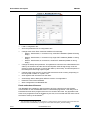
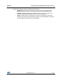
serial terminal on both, with the following configurations:
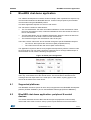
Figure 18. Serial port configuration
The application will listen for keys typed into one device and upon pressing the keyboard
return key, it will send them to the remote device. The remote device will listen for RF
messages and will output them in the serial port. In other words, anything typed in one
device will be visible to the other device.
6.1
Supported platforms
The BlueNRG chat demo (server & client roles) is supported on the BlueNRG development
platform (STEVAL-IDB002V1) and on the BlueNRG USB dongle (STEVAL-IDB003V1).
6.2
BlueNRG chat demo application: peripheral & central
devices
This section describes how two BLE chat devices (server-peripheral & client-central)
interact with each other in order to set up a point-to-point wireless chat communication.
DocID025464 Rev 3
37/47
47
BlueNRG chat demo application
UM1686
First, BlueNRG must be set up on both devices. In order to do this, a series of ACI
commands need to be sent to the processor.
6.2.1
Initialization
BlueNRG’s stack must be correctly initialized before establishing a connection with another
Bluetooth LE device. This is done with two commands
•
ACI_GATT_INIT
•
BLE Chat, “Server” role:
–
ACI_GAP_INIT(Role=0x01): peripheral.
BLE Chat, “Client role:
–
ACI_GAP_INIT(Role=0x03): central.
Peripheral & central BLE roles must be specified inside the GAP_INIT command. See ACI
documentation for more information on these commands and on those that follow.
6.2.2
Add service and characteristics
The chat service is added on the BLE chat, server role device using the following command:
aci_gatt_add_serv(UUID_TYPE_128, service_uuid, PRIMARY_SERVICE, 7,
&chatServHandle);
Where service_uuid is the private service UUID 128 bits allocated for the chat service
(Primary service).
The command will return the service handle in chatServHandle.
The TX characteristic is added using the following command (on BLE Chat, Server role
device):
aci_gatt_add_char(chatServHandle, UUID_TYPE_128, charUuidTX, 20,
CHAR_PROP_NOTIFY, ATTR_PERMISSION_NONE, 0, 16, 1, &TXCharHandle);
Where charUuidTX is the private characteristic UUID 128 bits allocated for the TX
characteristic (notify property). The characteristic handle is also returned (on
TXCharHandle).
The RX characteristic is added using the following command (on BLE Chat, Server role
device):
aci_gatt_add_char(chatServHandle, UUID_TYPE_128, charUuidRX, 20,
CHAR_PROP_WRITE|CHAR_PROP_WRITE_WITHOUT_RESP,
ATTR_PERMISSION_NONE, GATT_SERVER_ATTR_WRITE,16, 1, &RXCharHandle);
Where charUuidRX is the private characteristic UUID 128 bits allocated for the RX
characteristic (write property). The characteristic handle is also returned (on
RXCharHandle).
See ACI documentation for more information on these commands as well as those that
follow.
6.2.3
Set security requirements
BlueNRG exposes a command that the application can use to specify its security
requirements. If a characteristic has security restrictions, a pairing procedure must be
38/47
DocID025464 Rev 3
UM1686
BlueNRG chat demo application
initiated by the central in order to access that characteristic. On BLE chat demo, a fixed pin
(123456) is used as follows:
aci_gap_set_auth_requirement(MITM_PROTECTION_REQUIRED,OOB_AUTH_DATA_AB
SENT,NULL,7,16, USE_FIXED_PIN_FOR_PAIRING,123456,BONDING);
6.2.4
Enter connectable mode
On BLE chat, server role device uses GAP ACI commands to enter into general
discoverable mode:
aci_gap_set_discoverable(ADV_IND, 0, 0, PUBLIC_ADDR, NO_WHITE_LIST_USE,8,
local_name, 0, NULL, 0, 0);
The local_name parameter contains the name that will be present in advertising data, as
described in the Bluetooth core specification version 4.0, Vol. 3, Part C, Ch. 11.
6.2.5
Connection with central device
Once the BLE chat, server role device is put in a discoverable mode, it can be seen by the
BLE chat, client role device in order to create a Bluetooth low energy connection.
On BLE chat, client role device uses GAP ACI commands to connect with the BLE chat,
server role device in advertising mode:
aci_gap_create_connection(0x4000, 0x4000, PUBLIC_ADDR, bdaddr, PUBLIC_ADDR, 9,
9, 0, 60, 1000, 1000);
where bdaddr is the peer address of the BLE chat, client role device.
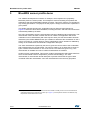
Once the 2 devices are connected, the user can set up a serial terminal and type into each
of them. The typed characters will be respectively stored in 2 buffers and upon pressing the
keyboard return key, BLE communication will work as follows:
1.
On BLE chat, server role device, the typed characters will be sent to BLE chat, client
role device by notifying the TX characteristic that has been previously added (after
notifications have been enabled). This can be done using the following command:
aci_gatt_update_char_value(chatServHandle,TXCharHandle,0,len,(tHalUint8 *)cmd+j)
2.
On BLE chat, client role device, the typed characters will be sent to the BLE chat,
server role device, by writing the RX characteristic that has been previously added.
This can be done using the following command:
aci_gatt_write_without_response(connection_handle, RX_HANDLE+1, len, (tHalUint8
*)cmd+j)
Where connection_handle is the handle returned on connection creation as a
parameter of the EVT_LE_CONN_COMPLETE event.
Once these ACI commands have been sent, the values of the TX, RX characteristics are
displayed on the serial terminals.
DocID025464 Rev 3
39/47
47
BlueNRG chat demo application
UM1686
Figure 19. BLE chat client example
40/47
Figure 20. BLE chat server example
DocID025464 Rev 3
UM1686
7
BlueNRG Beacon demonstration application
BlueNRG Beacon demonstration application
The software development kit contains another example, which shows how to configure a
BlueNRG device to advertise specific manufacturing data and allow another BLE device to
know if it is in the range of the BlueNRG beacon device.
7.1
Supported platforms
The BlueNRG Beacon demo is supported by the BlueNRG development platform (STEVALIDB002V1) and the BlueNRG USB dongle (STEVAL-IDB003V1).
7.1.1
Initialization
The BlueNRG stack must be correctly initialized as follows:
– ACI_GATT_INIT
– ACI_GAP_INIT(Role=0x01): peripheral
7.1.2
Define advertising data
The BLE Beacon application advertises the following manufacturing data:
Table 10. BlueNRG Beacon advertising manufacturing data
Note:
Data field
Description
Notes
Company identifier code
SIG company identifier
Default is 0x0030
(STMicroelectronics)
ID
Beacon ID
Fixed value
Location UUID
Beacons UUID
Used to distinguish specific
beacons from others
Major number
Identifier for a group of beacons
Used to group a related set of
beacons
Minor number
Identifier for a single beacon
Used to identify a single beacon
Tx Power
2's complement of the Tx power
Used to establish how far you
are from device
SIG company identifiers are available at:
https://www.bluetooth.org/en-us/specification/assigned-numbers/company-identifiers
DocID025464 Rev 3
41/47
47
BlueNRG Beacon demonstration application
7.1.3
UM1686
Entering non-connectable mode
The BLE Beacon device uses the GAP ACI command to enter non-connectable mode as
follows:
aci_gap_set_discoverable(ADV_NONCONN_IND, 160, 160, PUBLIC_ADDR,
NO_WHITE_LIST_USE,0, NULL, 0, NULL, 0, 0);
In order to advertise the specific selected manufacturer data, the BLE Beacon application
uses the following GAP ACIs:
/* Remove TX power level field from the advertising data: it is necessary to have enough
space for the beacon manufacturing data */
ret = aci_gap_delete_ad_type(AD_TYPE_TX_POWER_LEVEL);
/* Define the beacon manufacturing payload */
const uint8_t manuf_data[] = {26, AD_TYPE_MANUFACTURER_SPECIFIC_DATA,
0x30, 0x00, //Company identifier code (Default is 0x0030 - STMicroelectronics)
0x02,
// ID
0x15,
//Length of the remaining payload
0xE2, 0x0A, 0x39, 0xF4, 0x73, 0xF5, 0x4B, 0xC4, //Location UUID
0xA1, 0x2F, 0x17, 0xD1, 0xAD, 0x07, 0xA9, 0x61,
0x00, 0x00, // Major number
0x00, 0x00, // Minor number
0xC8
//2's complement of the Tx power (-56dB)};
};
/* Set the beacon manufacturing data on the advertising packet */
ret = aci_gap_update_adv_data(27, manuf_data);
42/47
DocID025464 Rev 3
UM1686
8
List of acronyms
List of acronyms
Table 11. List of acronyms used in this document
Term
Meaning
BLE
Bluetooth low energy
USB
Universal serial bus
DocID025464 Rev 3
43/47
47
Available board schematics
9
UM1686
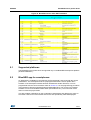
Available board schematics
Figure 21. BlueNRG daughterboard schematic
44/47
DocID025464 Rev 3
&
9 Q)
60'
'B9''
*1'
&
9 Q)
60'
&
9 Q)
60'
Q5(6(7
'B9''
&
9 Q)
60'
*1'
9''B
*1'
*1'
9''B
'B9''
670/&%8
45.-$#6 &
X) 9
60'
*1'
26&B287
0+]
<
*1'
.VSBUB $45$&.(3
%JHJLFZ /%
34 'BSOFMM 26&B,1
$B9''
8VHUB%XWWRQB
86(5B/('B
86(5B/('B
%OXH15*B,54
63,B026,
63,B0,62
63,B&/.
%OXH15*B&6
%OXH15*B567
9''B$
6:2
6:&/.
6:',2
&
9 Q)
60'
3%
3%
3%
3%
3%
3%
3%
3%
3%
3%
3%
3%%227
3%
3%
86(5B/('B
*1'
5
*1'
&
Q) 9
60'
8VHUB%XWWRQB
86(5B/('B
5
60'
*1'
25$1*(/('
'LJLNH\
1'
9LVKD\
7/02*6
60'
'
*1'
&
Q) 9
60'
8VHUB%XWWRQB
'B9''
*1'
6:'675,33,16
-
6TFS@#VUUPO@ 5
N
60'
'B9''
6:
386+%87721
&. .05*/)6
'LJLNH\ 1'
6TFS@#VUUPO@ 5
N
60'
60'
5('/('
'LJLNH\
1'
9LVKD\
7/06*6
60'
'
6:
386+%87721
&. .05*/)6
'LJLNH\ 1'
'B9''
'B9''
5
N
60'
%227
*1'
5 60'
5
N
60'
*1'
5
N
60'
5
N
60'
&
X) 9
60'
6:'%RRW8VHUB/HGV8VHUB%XWWRQV
*1'
'B9''
9''B
5
N
60'
'B9''
86%'0
86%'3
3$:.83
3$
3$
3$
3$
3$
3$
3$
3$
3$
3$
3$
3$
3$-7',
((3520B&6
3%-7'275$&(6:2
3$-7&.6:&/.
3$-7066:',2
3%1-7567
3&57&B$):.83
8VHUB%XWWRQB
3+B26&B,1
3+26&B287
1567
3&26&B,1
3&26&B287
%227
6:&/.
6:2
6:',2
Q5(6(7
*1'
*1'
9%$7
63,B026,
63,B&/.
%OXH15*B,54
&
&
Q) 9 X)
60' 60'
63,B026,
63,B&/.
63,B,54
7(67
9%$7
7(67
7(67
7(67
%/8(15*1
8
*1'
*1'
&
S)
60'
*1'
X+
&
9 Q)
60'
8
600)$
*1'
2KPP$
60'
/
45NJUF GMBU
%0"" $B9''
*1'
86%B9
9''
&
X) 9
60'
/
2KPP$
60'
*1'
%<3$66
9,1+
9,1
*1'
*1'
*1'
1&
9287
*1'
*1'
*1'
/
*1'
9%$7
%/8B9''
9''
*1'
%/8B9''
*1'
&
9 X)
60'
*1'
/
Q+
60'
*1'
86%B9
*1'
&
9 Q)
60'
'0
'3
-
86%$0DOH
((3520B&6 63,B&/. 63,B026, 63,B0,62 6
&
'
4
8
:01'
5
N
60'
'LJLNH\
0ROH[
60'
/05.06/5&%
&
&
Q) 9
60'
-JOF0IN
&
S)
60'
60'
&
S)
*1'
'
'
'
*1'
86%/&3
'
*1' 9%86
86%B9
&
9 Q)
60'
'0
'3
$17
*+] 5DLQVXQ
$1
&
S)
60'
8
*1'
050&7*
:
+2/'
'B9''
86%B'0
86%B'3
86%((3520
&
Q) 9
60'
*1'
9%$7
*1'
E#N -BZFS WFSTJPO
& 60'
S) /05.06/5&%
*1'
8)/FRQQHFWRU
*1'
8
&
60'
/
Q+
S)
60' /
60'
Q+ 60'
&
S)
60'
2KPP$
60'
%/8B9''
&
X) 9
60'
9''
Q+
&
S)
60'
60'
&
S)
/
*1'
&
9 X)
60'
%$7)
'
&
Q) 9
60'
*1'
&
S)
*1'
60'
1;6$BB0+]
&
Q) 9
60'
<
&
S)
60'
*1'
1;6$BN+]
9%$7
%/8B9''
<
*1'
9%$7
9%$7
*1'
&
Q) 9
60'
'B9''
*1'
*1'
&
S)
60'
8
/'6385
')1'H[SRVHGSDG
&
Q) 9
60'
&
S)
60'
&
9 X)
60'
&
Q) 9
60'
9%$7
6;7$/
6;7$/
5)
5)
9%$7
);7$/
);7$/
%OXH15*B567
60'
/
&
Q) 9
60'
3RZHU0JPWVWDJH
*1'
&
S)
60'
9''B
9''B
9''B
9''B$
9/&'
9''B
9''B
9''B
9''$
9/&'
966B
966B
966B
966$
(;326('B3$'
9/&'
%227
26&B,1
26&B287
Q5(6(7
8
(;3B3$'
63,B0,62
%OXH15*B&6
63,B0,62
63,B&6
7(67
9''9',*
6036),/7
12B6036
6036),/7
5(6(71
7(67
7(67
7(67
9''9
7(67
7(67
7(67
7(67
*1'
6,*
%OXHB15*
0&82VFLOODWRU0&89ROWDJH
*1'
9&&
(B3$'
DocID025464 Rev 3
UM1686
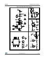
Available board schematics
Figure 22. BlueNRG USB dongle schematic
45/47
47
Revision history
10
UM1686
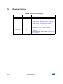
Revision history
Table 12. Document revision history
Date
Revision
28-Nov-2013
1
Initial release.
2
– Added reference to the STEVAL-IDB003V1 BlueNRG
USB Dongle.
– Added: Section 6: BlueNRG chat demo application
– Added: Section 8: List of acronyms
– Added: Section 9: Available board schematics
– Minor text edits throughout the document
3
– Added Section 3.2.3: GUI scripts window
– Added Section 3.2.4: GUI Beacon window
– Added Section 7: BlueNRG Beacon demonstration
application
– Renamed APIs with prefix BLUEHCI_ in Section 5.3.1
to 5.3.5 and 6.2.1.
24-Apr-2014
10-Dec-2014
46/47
Changes
DocID025464 Rev 3
UM1686
IMPORTANT NOTICE – PLEASE READ CAREFULLY
STMicroelectronics NV and its subsidiaries (“ST”) reserve the right to make changes, corrections, enhancements, modifications, and
improvements to ST products and/or to this document at any time without notice. Purchasers should obtain the latest relevant information on
ST products before placing orders. ST products are sold pursuant to ST’s terms and conditions of sale in place at the time of order
acknowledgement.
Purchasers are solely responsible for the choice, selection, and use of ST products and ST assumes no liability for application assistance or
the design of Purchasers’ products.
No license, express or implied, to any intellectual property right is granted by ST herein.
Resale of ST products with provisions different from the information set forth herein shall void any warranty granted by ST for such product.
ST and the ST logo are trademarks of ST. All other product or service names are the property of their respective owners.
Information in this document supersedes and replaces information previously supplied in any prior versions of this document.
© 2014 STMicroelectronics – All rights reserved
DocID025464 Rev 3
47/47
47