1
UM1872
User manual
Getting started with the Sub-1 GHz expansion board based on
SPSGRF-868 and SPSGRF-915 modules for STM32 Nucleo
Introduction
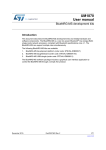
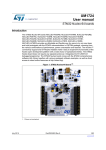
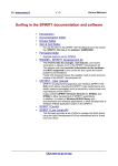
The X-NUCLEO-IDS01A4 and X-NUCLEO-IDS01A5 are evaluation boards intended to
provide a platform for testing the features and capabilities of the SPSGRF modules, based
on the SPIRIT1 low data rate, low power sub-1 GHz transceiver device.
These expansion boards can be plugged into the Arduino UNO R3 connectors of any
STM32 Nucleo board. The user can mount ST Morpho connectors if required. Other
expansion boards can easily be stacked to allow evaluation of different devices using sub-1
GHz communication.
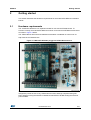
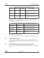
The boards are equipped with the following features:
• On-board SPSGRF module based on the SPIRIT1 sub-1 GHz transceiver device
• SPI EEPROM for saving parameters
• LED for user interface
• Jumper at 3V3 for checking the current consumption of the expansion board
Figure 1. Sub-1 GHz expansion board based on SPSGRF module for STM32
June 2015
DocID027622 Rev 2
1/21
www.st.com
21
Contents
UM1872
Contents
1
2
3
4
Description . . . . . . . . . . . . . . . . . . . . . . . . . . . . . . . . . . . . . . . . . . . . . . . . . 3
1.1
Typical applications . . . . . . . . . . . . . . . . . . . . . . . . . . . . . . . . . . . . . . . . . . 3
1.2
Abbreviations . . . . . . . . . . . . . . . . . . . . . . . . . . . . . . . . . . . . . . . . . . . . . . . 4
Getting started . . . . . . . . . . . . . . . . . . . . . . . . . . . . . . . . . . . . . . . . . . . . . . 5
2.1
Hardware requirements . . . . . . . . . . . . . . . . . . . . . . . . . . . . . . . . . . . . . . . 5
2.2
System requirements . . . . . . . . . . . . . . . . . . . . . . . . . . . . . . . . . . . . . . . . . 6
2.3
Setting up the board . . . . . . . . . . . . . . . . . . . . . . . . . . . . . . . . . . . . . . . . . . 6
Hardware description . . . . . . . . . . . . . . . . . . . . . . . . . . . . . . . . . . . . . . . . 7
3.1
Interconnection details . . . . . . . . . . . . . . . . . . . . . . . . . . . . . . . . . . . . . . . . 7
3.2
SPI and GPIO connection options . . . . . . . . . . . . . . . . . . . . . . . . . . . . . . . 8
3.3
Current measurement . . . . . . . . . . . . . . . . . . . . . . . . . . . . . . . . . . . . . . . . 9
3.4
X-NUCLEO-IDS01Ax component placement details . . . . . . . . . . . . . . . . . 9
Component description . . . . . . . . . . . . . . . . . . . . . . . . . . . . . . . . . . . . . 11
4.1
SPSGRF-868 / SPSGRF-915 module . . . . . . . . . . . . . . . . . . . . . . . . . . . .11
4.2
SPI EEPROM . . . . . . . . . . . . . . . . . . . . . . . . . . . . . . . . . . . . . . . . . . . . . . .11
5
Formal Notices Required by the U.S. Federal
Communications Commission (“FCC”) . . . . . . . . . . . . . . . . . . . . . . . . 12
6
Formal Notices Required by the Industry Canada (“IC”) . . . . . . . . . . 13
7
Hardware schematic diagrams . . . . . . . . . . . . . . . . . . . . . . . . . . . . . . . 14
8
Bill of material . . . . . . . . . . . . . . . . . . . . . . . . . . . . . . . . . . . . . . . . . . . . . 18
9
Revision history . . . . . . . . . . . . . . . . . . . . . . . . . . . . . . . . . . . . . . . . . . . 20
2/21
DocID027622 Rev 2
UM1872
1
Description
Description
The X-NUCLEO-IDS01A4 and X-NUCLEO-IDS01A5 boards contain the module SPSGRF868 or SPSGRF-915 based on SPIRIT1 low data rate, low power sub-1 GHz transceiver.
The PCB layout is the same for both boards, with the only difference being the module used
with it.
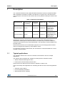
Table 1. Expansion board details
Evaluation board
RF
communication
frequency
X-NUCLEO-IDS01A4 868 MHz
X-NUCLEO-IDS01A5 915 MHz
Identification
resistors
Module used
R14 mounted
868 MHz RF expansion
board based on ETSI
SPSGRF-868 certified module
SPSGRF-868 for
STM32 Nucleo
R15 mounted
915 MHz RF expansion
board based on FCC
SPSGRF-915 and IC certified module
SPSGRF-915 for
STM32 Nucleo
Description
Identification of the RF communication frequency can be easily performed using the
identification resistors (R14 or R15) mounted on the PCBs. Only 1 of the two resistors is
mounted on the board to ensure quick identification. This information is also available in the
PCB silk screen.
Note that R14 and R15 are for identification purposes only, and changing these resistors
does not change the RF frequency of the SPIRIT1 device.
For information common to both boards, the nomenclature “X-NUCLEO-IDS01Ax” is used
hereafter in this document.
1.1
Typical applications
The evaluation boards can be used for evaluation of the SPIRIT1 device in multiple
applications.
The following demo examples are available for testing with the evaluation boards
• wM-Bus: Wireless Metering Bus demo
• Point-to-point communication protocol demo
Please refer to the data brief for the firmware, available on www.st.com.
Users can develop other applications for evaluating the devices. Some of these applications
are:
• Automatic meter reading
• Home and building automation
• WSN (wireless sensor network)
DocID027622 Rev 2
3/21
21
Description
UM1872
• Industrial monitoring and control
• Wireless fire and security alarm systems
1.2
Abbreviations
Table 2. Abbreviation
Term
AMR
EEPROM
Automatic meter reading
Electrically erasable programmable read only memory
GHz
Giga Hertz
GUI
Graphical user interface
LED
Light emitting diode
MCU
Microcontroller unit
P2P
Point-to-point communication
RF
Radio frequency communication
SPI
Serial peripheral interface
USB
Universal serial bus
wM-Bus
WSN
4/21
Meaning
Wireless metering bus
Wireless sensors network
DocID027622 Rev 2
UM1872
2
Getting started
Getting started
This section describes the hardware requirements for the X-NUCLEO-IDS01Ax evaluation
boards.
2.1
Hardware requirements
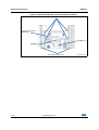
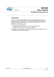
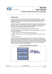
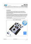
The X-NUCLEO-IDS01Ax is an expansion board for use with the STM32 Nucleo. To
function correctly, the X-NUCLEO-IDS01Ax must be connected to the STM32 Nucleo board
as shown in Figure 2 below.
The STM32 Nucleo firmware and related documentation is available on www.st.com at
http://www.st.com/stm32nucleo
Figure 2. X-NUCLEO-IDS01Ax plugged to STM32 Nucleo board
The interconnection between the STM32 Nucleo and the X-NUCLEO-IDS01Ax has been
designed to permit the use of any STM32 Nucleo board, although complete testing has
been performed using the NUCLEO-L053R8 and NUCLEO-F401RE hosting the ultra-low
power STM32.
DocID027622 Rev 2
5/21
21
Getting started
2.2
UM1872
System requirements
Using the Nucleo boards with the X-NUCLEO-IDS01Ax expansion board requires the
following software and hardware:
• Windows PC (XP, Vista, 7, 8) to install the firmware package
• USB type A to Mini-B USB cable to connect the Nucleo board to the PC
Installation of the board firmware package and the wM-Bus graphical user interface utility on
the user's PC requires the following:
• 128 MB of RAM
• Approximately 40 MB of hard disk space for the firmware
• Approximately 15 MB of hard disk space for the wM-Bus GUI
The use of the wM-Bus concentrator with the GUI requires additional boards to be
connected to the PC. The GUI can be used to check the wM-Bus communication example.
The Nucleo board acts as a meter and the STEVAL-IKR001Vx board connected to the PC
acts as a concentrator. Please note that the wM-Bus example is valid only for X-NUCLEOIDS01A4 (868 MHz version).
2.3
Setting up the board
Perform the following steps to set up the board:
6/21
1.
Check that the jumper on the J1 connector is connected. This jumper provides the
required voltage to the devices on the board
2.
Connect the X-NUCLEO-IDS01Ax to the Nucleo board from the top, as shown in
Figure 2.
3.
Power the Nucleo board using the Mini-B USB cable
4.
Program the firmware in the STM32 on the Nucleo board using the firmware example
provided
5.
Reset the MCU board using the reset button on the Nucleo board
6.
The evaluation kit is ready for use
DocID027622 Rev 2
UM1872
3
Hardware description
Hardware description
This section describes the X-NUCLEO-IDS01Ax features and provides information which
could be useful to understand the board schematics.
Interconnection details
The table below explains the connection details of the X-NUCLEO-IDS01Ax board with the
NUCLEO-L053R8 board.
A4
A5
A3
A2
A1
A0
VIN
GND
GND
5V
3V3
RESET
IOREF
NC
Signal
name
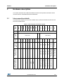
Table 3. Left connector connection details
5
6
PC1/ PB9
PC0/ PB8
ADC_IN11 (PC1) or
I2C1_SDA (PB9)
ADC_IN10(PC0) or
I2C1_SCL (PB8)
SPIRIT1_GPIO0 (Opt)
PA4
PB0
4
ADC_IN8
3
SPIRIT1_GPIO1 (Opt)
2
ADC_IN4
3V3
NUCLEO-L053R8
MCU signals
DocID027622 Rev 2
1
SPIRIT1_GPIO2 (Opt)
8
PA1
7
ADC_IN1
6
SPIRIT1_CSn (Opt)
5
PA0
4
ADC_IN0
3
SPIRIT1_GPIO3 (Opt)
2
GND
1
CN8 Analog
GND
CN6 Power
NUCLEOL053R8
(MCU port)
Pin#
Connector
name
Left connector
X-NUCLEO-IDS01Ax
Expansion board signals
3.1
7/21
21
Hardware description
UM1872
D2
D1
D0
2
1
PC7
PA9
PA8
PB10
PB4
PB5
PB3
PA10
PA2
PA3
TIM2_CH3
TIM22_CH1
TIM2_CH2_SCK
USART2_TX
USART2_RX
EEPROM_nS
LED1
CLK
D3
3
TIM22_CH2
D4
4
SPIRIT1_GPIO3
D5
5
PB6
D6
6
SPI1_CS
D7
7
SPIRIT1_CSn
D8
8
PA7
D9
1
TIM22_CH2
D10
2
MOSI(SPIRIT1)
D11
3
PA6
D12
4
SPI1_MISO
D13
GND
AREF
D14
D15
Signal
name
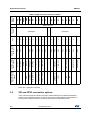
Table 4. Right connector connection details
CLK (Opt)
MISO (SPIRIT1)
Ground
GND
5
PA5
7
AVDD
6
SPI1_SCK
8
PB9
PB8
I2C1_SCL
9
I2C1_SDA
Pin#
NUCLEO-L053R8
MCU port
X-NUCLEO-IDS01Ax
Expansion boards
signals
10
NUCLEO-L053R8
MCU signals
CN5 Digital
CN9 Digital
SDn
Connector
name
Right connector
Note: Opt = Optional connection
3.2
SPI and GPIO connection options
Table 5 shows the SPI and GPIO connection options between the STM32 and SPIRIT1
hosted on the SPSGRF module. These can be used to enable different configurations in
cases where a signal conflict occurs when using with other expansion board.
8/21
DocID027622 Rev 2
UM1872
Hardware description
Table 5. SPIRIT1 interface (optional) with Nucleo board
SPIRIT1 signal
SPSGRF pin
Default STM32
port
GPIO3
1 - SP1_GPIO3
PC7
PA0
To use optional connection mount R6,
demount R1
CSn
10 - SPI_CS
PB6
PA1
To use optional connection mount R5,
demount R2
SCLK
7 - SPI_CLK
PB3
PA5
To use optional connection mount R7,
demount R4
Optional STM32 port
In addition, to use the additional connections to the SPIRIT1 module and to use the onboard EEPROM, use the options in Table 6.
Table 6. SPIRIT1 interface with Nucleo board (additional connections)
Signal
Default connection
Optional STM32 connection
SPIRIT1 GPIO2
(SPSGRF pin 2)
Not connected
PA4
To use optional connection mount R8
SPIRIT1 GPIO1
(SPSGRF pin 3)
Not connected
PB0
To use optional connection mount R9
SPIRIT1 GPIO0
(SPSGRF pin 4)
Not connected
PC1
To use optional connection mount R10
EEPROM nS
Not connected
PB10
To use EEPROM, mount R3
Please refer to the schematics for details.
To use the optional connections, modify the firmware based on the STM32 resources used.
3.3
Current measurement
To monitor the power consumption of the entire SPIRIT1 X-NUCLEO-IDS01Ax board,
jumper J1 can be used. Connect an ammeter probe between pins 1 and 2 of the connector
for measurements.
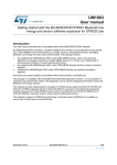
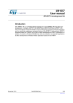
3.4
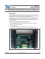
X-NUCLEO-IDS01Ax component placement details
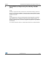
Figure 3 shows the component placement on the SPIRIT1 expansion X-NUCLEO-IDS01Ax
board.
DocID027622 Rev 2
9/21
21
Hardware description
UM1872
Figure 3. X-NUCLEO-IDS01Ax component placement details
$UGXLQR8125&RQQHFWRUV
)UHTXHQF\DQGERDUG
LGHQWLILFDWLRQ
636*5)[[[
((3520
670RUSKR&RQQHFWRUV
10/21
DocID027622 Rev 2
*63*6*
UM1872
4
Component description
Component description
This section describes the devices on the board.
4.1
SPSGRF-868 / SPSGRF-915 module
The SPSGRF modules are based on the SPIRIT1 device which is a low data rate, low
power sub-1 GHz transceiver. The SPSGRF-868 module is for 868 MHz RF communication
and the SPSGRF-915 module is for 915 MHz RF communication. The SPSGRF-868 is an
ETSI certified module and SPSGRF-915 is an FCC and IC certified module SPSGRF-915
(FCC ID: S9NSPSGRF and IC: 8976C-SPSGRF).
The interface of the device to the STM32 Nucleo boards is through an SPI interface and
some GPIOs. The SPSGRF module also integrates the balun BALF-SPI-01D3 and a chip
antenna.
The part numbers used to develop this application are shown in Table 7.
Table 7. SPIRIT1 details
Features
Description
Order code
SPSGRF-868, SPSGRF-915
Package
SMD 11 pin
Operating voltage
1.8 to 3.6 V
The SPIRIT1 device is designed to operate both in the license-free ISM and SRD frequency
bands at 169, 315, 433, 868, and 915 MHz.
The SPSGRF modules are designed for fixed frequencies specified in the part number.
4.2
SPI EEPROM
The M95640-R is a 64 Kbit serial SPI bus EEPROM with high-speed clock interface. The
device can be used to store the configuration parameters related to application or settings of
the SPIRIT1 device.
The part numbers used to develop this application are shown in Table 8.
Table 8. SPI EEPROM details
Features
Description
Order code
M95640-RMC6TG
Package
MLP8
Operating voltage
1.8 to 5.5 V
To use the on-board SPI EEPROM, mount the R3 resistor on the board.
DocID027622 Rev 2
11/21
21
Formal Notices Required by the U.S. Federal Communications Commission (“FCC”)
5
UM1872
Formal Notices Required by the U.S. Federal
Communications Commission (“FCC”)
Any changes or modifications to this equipment not expressly approved by
STMicroelectronics may cause harmful interference and void the user’s authority to operate
this equipment.
The X-NUCLEO-IDS01A5 complies with Part 15 of the FCC Rules. Operation is subject to
the following two conditions: (1) this device may not cause harmful interference, and (2) this
device must accept any interference received, including any interference that may cause
undesired operation.
The X-NUCLEO-IDS01A5 contains FCC ID: S9NSPSGRF.
12/21
DocID027622 Rev 2
UM1872
6
Formal Notices Required by the Industry Canada (“IC”)
Formal Notices Required by the Industry Canada
(“IC”)
English:
This device complies with Industry Canada licence-exempt RSS standard(s). Operation is
subject to the following two conditions: (1) this device may not cause interference, and (2)
this device must accept any interference, including interference that may cause undesired
operation of the device.
French:
Le présent appareil est conforme aux CNR d'Industrie Canada applicables aux appareils
radio exempts de licence. 'exploitation est autorisée aux deux conditions suivantes : (1)
l'appareil ne doit pas produire de brouillage, et (2) l'utilisateur de l'appareil doit accepter tout
brouillage radioélectrique subi, même si le brouillage est susceptible d'en compromettre le
fonctionnement.
The X-NUCLEO-IDS01A5 contains IC certified module SPBTLE-RF (IC:8976C-SPSGRF).
DocID027622 Rev 2
13/21
21
Hardware schematic diagrams
7
UM1872
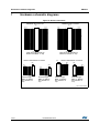
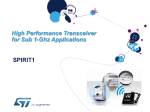
Hardware schematic diagrams
Figure 4. Nucleo connectors
MORPHO SX Connector
MORPHO DX Connector
CN7
PC10
PC12
VDD
BOO T0
NC /PF6
NC /PF7
PA13
PA14
PA15
GN D
PB7
PC13
PC14
PC15
PH0/PF0/PD0
PH1/PF1/PD1
VL CD /VBAT
PC2
PC3
1
3
5
7
9
11
13
15
17
19
21
23
25
27
29
31
33
35
37
CN 10
2
4
6
8
10
12
14
16
18
20
22
24
26
28
30
32
34
36
38
PC11
PD2
E5 V
GN D
NC /
IOR EF
RESE T
+3V 3
+5V
GN D
GN D
VIN
NC /
PA 0
PA 1
PA 4
PB 0
PC1
PC0
1
3
5
7
9
11
13
15
17
19
21
23
25
27
29
31
33
35
37
PC9
PB 8
PB 9
AV DD
GN D
PA 5
PA 6
PA 7
PB 6
PC7
PA 9
PA 8
PB1 0
PB 4
PB 5
PB 3
PA1 0
PA 2
PA 3
HE ADER 19x2
Pass-Through: Female on
Bottom and Male on Top
CN5
Arduino UNO R3SX Connector
HE ADER 8
Pass-Through:
Male on Bottom
and Female on
Top
CN8
PA 0
PA 1
PA 4
PB 0
PC1
PC0
1
2
3
4
5
6
HE ADER 6
Pass-Through:
Male on Bottom
and Female on
Top
Arduino UNO R3 DX Connector
10
9
8
7
6
5
4
3
2
1
CN6
1
2
3
4
5
6
7
8
PC8
PC6
PC5
U5 V
PD8
PA1 2
PA1 1
PB1 2
PB11 /NC
GN D
PB 2
PB 1
PB1 5
PB1 4
PB1 3
AGN D
PC4
NC /PF 5
NC /PF 4
HE ADER 1 9x2
Pass-Through: Female on
Bottom and Male on Top
NC /
IOR EF
RESET
+3V 3
+5V
GN D
GN D
VIN
2
4
6
8
10
12
14
16
18
20
22
24
26
28
30
32
34
36
38
PB 8
PB 9
AV DD
GN D
PA 5
PA 6
PA 7
PB 6
PC7
PA 9
HE ADER 10
Pass-Through:
Male on Bottom
and Female on
Top
CN9
8
7
6
5
4
3
2
1
PA 8
PB1 0
PB 4
PB 5
PB 3
PA1 0
PA 2
PA 3
HE ADER 8
Pass-Through:
Male on Bottom
and Female on
Top
GSPG11032015DI0950
14/21
DocID027622 Rev 2
UM1872
Hardware schematic diagrams
Figure 5. SPSGRF-868, SPSGRF-915
8
$17
63,B*3,2
63,B*3,2
63,B*3,2
9&&B5)
63B*3,2
6'1
63B*3,2
63,B&6
63B*3,2
63,B026,
63B*3,2
63,B0,62
9,1
636*5)
*1'
63,B&/.
6'Q
&61
026,
0,62
&/.
63,B*3,2
*63*6*
DocID027622 Rev 2
15/21
21
Hardware schematic diagrams
UM1872
Figure 6. Nucleo connections
9
9
9&&B5)
-
3$
+($'(5[
*1'
3$
3$
3&
3%
3%
3%
5
5
5
5
60'63,B*3,2
3$
&61
60'
60'
3$
Q6
1RWPRXQWHG
&/.
60'
3%
0,62
3$
3&
026,
3$
60'
3%
5
5
5
636*5)B0+]
636*5)B0+]
1RWPRXQWHG
60'
60'
6'Q
5
&61
60'
1RWPRXQWHG
5
60'63,B*3,2
1RWPRXQWHG
5
&/.
60'
1RWPRXQWHG
5
60'63,B*3,2
1RWPRXQWHG
5
60'63,B*3,2
1RWPRXQWHG
5
60'63,B*3,2
1RWPRXQWHG
'
5('/('
'LJLNH\
*1'
1'
9LVKD\
7/06*6
60'
*63*6*
16/21
DocID027622 Rev 2
UM1872
Hardware schematic diagrams
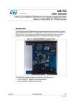
Figure 7. EEPROM
9
&
9 Q)
60' 5
N
60'
8
6
&
'
4
9&&
(B3$'
Q6
&/.
026,
0,62
*1'
*1'
*1'
DocID027622 Rev 2
:
+2/'
050&7*
*63*6*
17/21
21
Bill of material
8
UM1872
Bill of material
Table 9. BOM list
Item
Qty
Ref.
Part / Value
Type / Add.
Notes
Toler.
Package
Manuf.
Part num./
Order code
Supplier
Suppl.
order
code
ST
SUPPLY
SPSGR
F-868
ST
SUPPLY
SPSGR
F-868
X-NUCLEO-IDS01A4 (SPSGRF-868 Nucleo expansion board specific components)
1
1
U1
SPSGRF-868
2
1
R14
0
R15
NOT MOUNTED
SMD 11 pins
ST
SPSGRF-868
SMD 0805
ANY
ANY
X-NUCLEO-IDS01A5 (SPSGRF-915 Nucleo expansion board specific components)
1
1
U1
SPSGRF-915
2
1
R15
0
R14
NOT MOUNTED
SMD 11 pins
ST
SPSGRF-868
SMD 0805
ANY
ANY
X-NUCLEO-IDS01A4, X-NUCLEO-IDS01A5: SPIRIT1 expansion board common components
3
4
5
6
1
1
2
2
U2
M95640RMC6TG
UFDFPN8
2X3 mm
(MLP8)
ST
M95640RMC6TG
ST
SUPPLY
M95640RMC6T
G
CN5
Arduino
Connector
CN5 10 pins
PassThrough: Male
on Bottom,
Female on
Top. 10x1
2.54mm pitch
SAMTE
C
SSQ-110-03F-S
Farnell
2283783
CN6,
CN9
Arduino
Connectors
CN6 and CN9
8 pins
PassThrough: Male
on Bottom,
Female on
Top. 8x1
2.54mm pitch
SAMTE
C
SSQ-108-03F-S
Farnell
2283782
CN7,
CN10
MORPHO
Connectors
CN7 and
CN10 38 pins
PassThrough:
Female on
Bottom, Male
on Top. 19x2
2.54mm pitch
PassThrough: Male
on Bottom,
Female on
Top. 6x1
2.54mm pitch
SAMTE
C
SSQ-106-03G-S
Farnell
2283759
SMD 0402
Murata
GRM155R71
C104KA88
7
1
CN8
Arduino
Connector
CN8 6 pins
8
1
C1
100nF
18/21
NOT MOUNTED
Ceramic X7R
±10%
DocID027622 Rev 2
UM1872
Bill of material
Table 9. BOM list (continued)
Package
Manuf.
Part num./
Order code
Through hole
2 x1 2.54 mm
pitch
ANY
ANY
±1%
SMD 0805
ANY
ANY
100 k
±1%
SMD 0805
ANY
ANY
R13
680
±1%
SMD 0805
ANY
ANY
D1
RED LED
SMD 0603
Vishay
TLMS1100GS08
Item
Qty
Ref.
Part / Value
9
1
J1
Jumper
10
12
R1,
R2,
R3,
R4,
R5,
R6,
R7,
R8,
R9,
R10,
R14,
R15
0
11
1
R12
12
1
13
1
Type / Add.
Notes
Toler.
R3, R5, R6, R7,
R8, R9, R10,R15
NOT MOUNTED
DocID027622 Rev 2
Supplier
Suppl.
order
code
Digikey
7511182-1ND
19/21
21
Revision history
9
UM1872
Revision history
Table 10. Document revision history
20/21
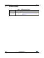
Date
Revision
Changes
20-May-2015
1
Initial release.
23-Jun-2015
2
Added:
- Section 6: Formal Notices Required by the Industry
Canada (“IC”).
DocID027622 Rev 2
UM1872
IMPORTANT NOTICE – PLEASE READ CAREFULLY
STMicroelectronics NV and its subsidiaries (“ST”) reserve the right to make changes, corrections, enhancements, modifications, and
improvements to ST products and/or to this document at any time without notice. Purchasers should obtain the latest relevant information on
ST products before placing orders. ST products are sold pursuant to ST’s terms and conditions of sale in place at the time of order
acknowledgement.
Purchasers are solely responsible for the choice, selection, and use of ST products and ST assumes no liability for application assistance or
the design of Purchasers’ products.
No license, express or implied, to any intellectual property right is granted by ST herein.
Resale of ST products with provisions different from the information set forth herein shall void any warranty granted by ST for such product.
ST and the ST logo are trademarks of ST. All other product or service names are the property of their respective owners.
Information in this document supersedes and replaces information previously supplied in any prior versions of this document.
© 2015 STMicroelectronics – All rights reserved
DocID027622 Rev 2
21/21
21