Download Main Menu (continued)

Transcript
Operating Instructions
LCD Video Monitor
Model No.
Model No.
BT-LH2550P
BT-LH2550E
DEUTSCH
Für Erlauterungen in Deutsch, konsultieren Sie bitte die mitgelieferte CD-ROM.
FRANÇAIS
Pour des explications en français, veuillez vous reporter au CD-ROM fourni.
ITALIANO
Per le istruzioni in italiano, vedere il CD-ROM in dotazione.
ESPAÑOL
Para la explicación en español, consulte el CD-ROM uministrado.
Before operating this product, please read the instructions carefully and save this manual for future use.
S1108T0 -P D
Printed in Japan
ENGLISH
VQT2A05
Read this first ! (for BT-LH2550P)
CAUTION:
In order to maintain adequate ventilation, do not
install or place this unit in a bookcase, built-in
cabinet or any other confined space. To prevent
risk of electric shock or fire hazard due to
overheating, ensure that curtains and any other
materials do not obstruct the ventilation.
CAUTION:
TO REDUCE THE RISK OF FIRE OR SHOCK
HAZARD AND ANNOYING INTERFERENCE, USE
THE RECOMMENDED ACCESSORIES ONLY.
CAUTION:
This apparatus can be operated at a voltage in the
range of 100 - 240 V AC. Voltages other than 120 V
are not intended for U.S.A. and Canada.
CAUTION:
■ THIS EQUIPMENT MUST BE GROUNDED
To ensure safe operation, the three-pin plug must be
inserted only into a standard three-pin power outlet
which is effectively grounded through normal
household wiring. Extension cords used with the
equipment must have three cores and be correctly
wired to provide connection to the ground. Wrongly
wired extension cords are a major cause of fatalities.
The fact that the equipment operates satisfactorily
does not imply that the power outlet is grounded or that
the installation is completely safe. For your safety, if
you are in any doubt about the effective grounding of
the power outlet, please consult a qualified electrician.
CAUTION:
THE MAINS PLUG OF THE POWER SUPPLY CORD
SHALL REMAIN READILY OPERABLE.
THE AC RECEPTACLE (MAINS SOCKET OUTLET)
SHALL BE INSTALLED NEAR THE EQUIPMENT
AND SHALL BE EASILY ACCESSIBLE. TO
COMPLETELY DISCONNECT THIS EQUIPMENT
FROM THE AC MAINS, DISCONNECT THE POWER
CORD PLUG FROM THE AC RECEPTACLE.
WARNING:
• TO REDUCE THE RISK OF FIRE OR SHOCK
HAZARD, DO NOT EXPOSE THIS EQUIPMENT
TO RAIN OR MOISTURE.
• TO REDUCE THE RISK OF FIRE OR SHOCK
HAZARD, KEEP THIS EQUIPMENT AWAY
FROM ALL LIQUIDS. USE AND STORE ONLY
IN LOCATIONS WHICH ARE NOT EXPOSED
TO THE RISK OF DRIPPING OR SPLASHING
LIQUIDS, AND DO NOT PLACE ANY LIQUID
CONTAINERS ON TOP OF THE EQUIPMENT.
Operation at a voltage other than 120 V AC may
require the use of a different AC plug. Please contact
either a local or foreign Panasonic authorized service
center for assistance in selecting an alternate AC plug.
CAUTION:
This Monitor is for use only with Panasonic Wall
Mount Adaptor, BT-WMA26G. Use with other Wall
Mount is capable of resulting in instability causing
possible injury.
CAUTION:
Excessive sound pressure from earphones and
headphones can cause hearing loss.
WARNING:
Installation should only be performed by qualified
installation personnel.
Improper installation may result in the entire
apparatus falling down and causing injury.
CAUTION:
Check the installation at least once a year.
An improper installation could cause the monitor to
fall off resulting in personal injury.
CAUTION:
Remove the wall mount adaptor when not used.
Otherwise people moving in the vicinity of the
monitor could get caught on the bracket and be
injured.
AC Adapter
The rating plate is on the underside of the AC
Adapter.
indicates safety information.
Notice (U.S.A. only):
This product has a fluorescent lamp that contains mercury. Disposal may be regulated in your community due to
environmental considerations. For disposal or recycling information, please contact your local authorities, or the
Electronic Industries Alliance:
http://www.eiae.org.
2
Read this first ! (for BT-LH2550P) (continued)
FCC NOTICE (USA)
Declaration of Conformity
Model Number:
BT-LH2550P
Trade Name:
Panasonic
Responsible Party:
Panasonic Corporation of North America
One Panasonic Way, Secaucus, NJ07094
Support contact:
Panasonic Broadcast & Television Systems Company
1-800-524-1448
This device complies with Part 15 of FCC Rules.
Operation is subject to the following two conditions:
(1) This device may not cause harmful interference, and (2) this device must accept any interference
received, including interference that may cause undesired operation.
To assure continued compliance, follow the attached installation instructions and do not make any unauthorized modifications.
Note:
This equipment has been tested and found to comply with the limits for a class B digital device, pursuant to
Part 15 of the FCC Rules. These limits are designed to provide reasonable protection against harmful interference in a residential installation. This equipment generates, uses, and can radiate radio frequency
energy, and if not installed and used in accordance with the instructions, may cause harmful interference to
radio communications. However, there is no guarantee that interference will not occur in a particular installation. If this equipment does cause harmful interference to radio or television reception, which can be
determined by turning the equipment off and on, the user is encouraged to try to correct the interference by
one of the following measures:
• Reorient or relocate the receiving antenna.
• Increase the separation between the equipment and receiver.
• Connect the equipment into an outlet on a circuit different from that to which the receiver is connected.
• Consult the dealer or an experienced radio/TV technician for help.
The user may find the booklet “Something About Interference” available from FCC local regional offices helpful.
Warning:
To assure continued FCC emission limit compliance, follow the attached installation instructions and the user
must use only shielded interface cables when connecting to host computer or peripheral devices. If DVI-D port
is to be used it must connected to PC by compatible interface cable with two ferrite cores. Also, any
unauthorized changes or modifications to this equipment could void the user’s authority to operate this device.
IMPORTANT SAFETY INSTRUCTIONS
1)
2)
3)
4)
5)
6)
7)
8)
Read these instructions.
Keep these instructions.
Heed all warnings.
Follow all instructions.
Do not use this apparatus near water.
Clean only with dry cloth.
Do not block any ventilation openings. Install in accordance with the manufacturer’s instructions.
Do not install near any heat sources such as radiators, heat registers, stoves, or other apparatus (including amplifiers) that produce heat.
9) Do not defeat the safety purpose of the polarized or grounding-type plug. A polarized plug has two blades
with one wider than the other. A grounding-type plug has two blades and a third grounding prong. The
wide blade or the third prong are provided for your safety. If the provided plug does not fit into your outlet,
consult an electrician for replacement of the obsolete outlet.
10) Protect the power cord from being walked on or pinched particularly at plugs, convenience receptacles,
and the point where they exit from the apparatus.
11) Only use attachments/accessories specified by the manufacturer.
12) Use only with the cart, stand, tripod, bracket, or table specified by the manufacturer, or sold
with the apparatus. When a cart is used, use caution when moving the cart/apparatus combination to avoid injury from tip-over.
13) Unplug this apparatus during lightning storms or when unused for long periods of time.
14) Refer all servicing to qualified service personnel. Servicing is required when the apparatus
has been damaged in any way, such as power-supply cord or plug is damaged, liquid has been spilled or
objects have fallen into the apparatus, the apparatus has been exposed to rain or moisture, does not operate normally, or has been dropped.
S3125A
3
Read this first ! (for BT-LH2550E)
■ THIS EQUIPMENT MUST BE EARTHED
To ensure safe operation, the three-pin plug
must be inserted only into a standard three-pin
power point which is effectively earthed through
normal house-hold wiring.
Extension cords used with the equipment must
have three cores and be correctly wired to
provide connection to the earth. Wrongly wired
extension cords are a major cause of fatalities.
The fact that the equipment operates
satisfactorily does not imply that the power point
is earthed or that the installation is completely
safe. For your safety, if you are in any doubt
about the effective earthing of the power point,
please consult a qualified electrician.
■ DO NOT REMOVE PANEL COVERS BY
UNSCREWING THEM.
To reduce the risk of electric shock, do not
remove covers. No user serviceable parts
inside.
Refer servicing to qualified service personnel.
CAUTION:
TO REDUCE THE RISK OF FIRE OR SHOCK
HAZARD AND ANNOYING INTERFERENCE, USE
THE RECOMMENDED ACCESSORIES ONLY.
CAUTION:
In order to maintain adequate ventilation, do not
install or place this unit in a bookcase, built-in
cabinet or any other confined space. To prevent
risk of electric shock or fire hazard due to
overheating, ensure that curtains and any other
materials do not obstruct the ventilation.
CAUTION:
This Monitor is for use only with Panasonic Wall
Mount Adaptor, BT-WMA26G. Use with other Wall
Mount is capable of resulting in instability causing
possible injury.
CAUTION:
Excessive sound pressure from earphones and
headphones can cause hearing loss.
CAUTION:
THE MAINS PLUG OF THE POWER SUPPLY
CORD SHALL REMAIN READILY OPERABLE.
THE AC RECEPTACLE (MAINS SOCKET OUTLET)
SHALL BE INSTALLED NEAR THE EQUIPMENT
AND SHALL BE EASILY ACCESSIBLE. TO
COMPLETELY DISCONNECT THIS EQUIPMENT
FROM THE AC MAINS, DISCONNECT THE POWER
CORD PLUG FROM THE AC RECEPTACLE.
WARNING:
• TO REDUCE THE RISK OF FIRE OR SHOCK
HAZARD, DO NOT EXPOSE THIS EQUIPMENT
TO RAIN OR MOISTURE.
• TO REDUCE THE RISK OF FIRE OR SHOCK
HAZARD, KEEP THIS EQUIPMENT AWAY
FROM ALL LIQUIDS. USE AND STORE ONLY
IN LOCATIONS WHICH ARE NOT EXPOSED
TO THE RISK OF DRIPPING OR SPLASHING
LIQUIDS, AND DO NOT PLACE ANY LIQUID
CONTAINERS ON TOP OF THE EQUIPMENT.
indicates safety information.
4
WARNING:
Installation should only be performed by qualified
installation personnel.
Improper installation may result in the entire
apparatus falling down and causing injury.
CAUTION:
Check the installation at least once a year.
An improper installation could cause the monitor to
fall off resulting in personal injury.
CAUTION:
Remove the wall mount adaptor when not used.
Otherwise people moving in the vicinity of the
monitor could get caught on the bracket and be
injured
AC Adapter
The rating plate is on the underside of the AC
Adapter.
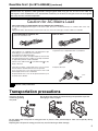
Read this first ! (for BT-LH2550E) (continued)
Operating precaution
Operation near any appliance which generates strong magnetic fields may give rise to noise in the video and
audio signals. If this should be the case, deal with the situation by, for instance, moving the source of the magnetic
fields away from the unit before operation.
Caution for AC Mains Lead
FOR YOUR SAFETY PLEASE READ THE FOLLOWING TEXT CAREFULLY.
This product is equipped with 2 types of AC mains cable. One is for continental Europe, etc. and the other one is only
for U.K.
Appropriate mains cable must be used in each local area, since the other type of mains cable is not suitable.
FOR CONTINENTAL EUROPE, ETC.
Not to be used in the U.K.
FOR U.K. ONLY
FOR U.K. ONLY
This appliance is supplied with a moulded three pin
mains plug for your safety and convenience.
A 13 amp fuse is fitted in this plug.
Should the fuse need to be replaced please ensure that
the replacement fuse has a rating of 13 amps and that it
is approved by ASTA or BSI to BS1362.
on the
Check for the ASTA mark
or the BSI mark
body of the fuse.
If the plug contains a removable fuse cover you must
ensure that it is refitted when the fuse is replaced.
If you lose the fuse cover the plug must not be used
until a replacement cover is obtained.
A replacement fuse cover can be purchased from your
local Panasonic Dealer.
How to replace the fuse
1. Open the fuse compartment with a screwdriver.
2. Replace the fuse.
Fuse
indicates safety information.
Transportation precautions
Do not try to lift the
monitor by grabbing
the panel.
Do not place the monitor face down during transportation to prevent
damaging it. Keep it upright.
Do not expose the LCD panel to strong pressure or pressure from pointed objects. Take care especially during
transportation.
Exposing the LCD panel to strong pressure may result in blurring or other damage.
5
Read this first !
EMC NOTICE FOR THE PURCHASER/USER OF THE APPARATUS
1. Applicable standards and operating environment (BT-LH2550E)
The apparatus is compliant with:
• standards EN55103-1 and EN550103-2 1996.and
• electromagnetic environments E1, E2, E3 and E4
2. Pre-requisite conditions to achieving compliance with the above standards
<1> Peripheral equipment to be connected to the apparatus and special connecting cables
• The purchaser/user is urged to use only equipment which has been recommended by us as
peripheral equipment to be connected to the apparatus.
• The purchaser/user is urged to use only the connecting cables described below.
<2> For the connecting cables, use shielded cables which suit the intended purpose of the
apparatus.
• Video signal connecting cables
Use double shielded coaxial cables, which are designed for 75-ohm type high-frequency applications,
for SDI (Serial Digital Interface).
Coaxial cables, which are designed for 75-ohm type high-frequency applications, are recommended
for analog video signals.
• Audio signal connecting cables
If your apparatus supports AES/EBU serial digital audio signals, use cables designed for AES/EBU.
Use shielded cables, which provide quality performance for high-frequency transmission applications,
for analog audio signals.
• Other connecting cables (IEEE1394, USB)
Use shielded cables, which provide quality performance for high-frequency applications, as
connecting cables.
• When connecting to the DVI signal terminal, use a cable with a ferrite core.
• If your apparatus is supplied with ferrite core(s), they must be attached on cable(s) following
instructions in this manual.
3. Performance level
The performance level of the apparatus is equivalent to or better than the performance level required by
these standards.
However, the apparatus may be adversely affected by interference if it is being used in an EMC environment,
such as an area where strong electromagnetic fields are generated (by the presence of signal transmission
towers, cellular phones, etc.). In order to minimize the adverse effects of the interference on the apparatus in
cases like this, it is recommended that the following steps be taken with the apparatus being affected and
with its operating environment:
1. Place the apparatus at a distance from the source of the interference.
2. Change the direction of the apparatus.
3. Change the connection method used for the apparatus.
4. Connect the apparatus to another power outlet where the power is not shared by any other
appliances.
6
Precautions for Use
• The LCD screen is manufactured to precise specifications. Although over 99.99% of the pixels function normally,
0.01% of the pixels are either missing or constantly lit (red, blue or green). This is normal and not a cause for
concern.
• The liquid crystal protection panel is a specially manufactured component. Wiping it with a hard cloth, or rubbing
it vigorously will scratch the surface.
• If a still image is displayed for an extended period of time, it may generate a temporary afterimage (phosphor
burn-in). (However, such images can be removed by displaying normal video for a while.)
• The response speed and brightness of liquid crystal vary with ambient temperatures.
• Let authorized service person handle installation.
Be sure to consult with the service person about the installation. Make sure that the wall is strong enough to
endure the weight of this unit including the mount fittings. If not strong enough, it may fall off resulting in injury.
• Do not install the unit in a place exposed to direct sunlight, as it may damage the cabinet and the LCD screen.
• Do not install the unit in locations where enough space cannot be provided around it as heat may build up inside
preventing normal operation. Be sure to provide enough space around the unit.
• Exposing the LCD screen to intense light sources will impair its characteristics and lower image quality.
• In an environment exposed to drastic temperature fluctuations, condensation may build up on and inside the
LCD screen. This may lower the quality of the screen and may damage it.
• Some video images may appear blurred on the screen.
• Leaving the unit in a location exposed to high temperature and humidity for an extended period of time may
damage the LCD screen and cause blurring.
Contents
Read this first ! . . . . . . . . . . . . . . . . . . . . . . . . . . . . . 2
Transportation precautions . . . . . . . . . . . . . . . . . . . 5
Precautions for Use . . . . . . . . . . . . . . . . . . . . . . . . . 7
Standard accessories . . . . . . . . . . . . . . . . . . . . . . . 7
Optional units . . . . . . . . . . . . . . . . . . . . . . . . . . . . . . 7
Outline . . . . . . . . . . . . . . . . . . . . . . . . . . . . . . . . . . . . 8
Dimensions . . . . . . . . . . . . . . . . . . . . . . . . . . . . . . . . 9
Controls and Their Functions . . . . . . . . . . . . . . . . 10
Video monitor unit ..................................................10
Front panel controls ...............................................11
Rear panel terminals..............................................12
AC Adapter.............................................................13
Power Supply. . . . . . . . . . . . . . . . . . . . . . . . . . . . . . 14
How to Use the On Screen Menu. . . . . . . . . . . . . . 15
User Data . . . . . . . . . . . . . . . . . . . . . . . . . . . . . . . . . 20
Main Menu . . . . . . . . . . . . . . . . . . . . . . . . . . . . . . . . 21
Menu configuration ................................................21
MARKER................................................................22
Marker types ..........................................................24
VIDEO CONFIG .....................................................26
SYSTEM CONFIG .................................................29
FUNCTION.............................................................32
GPI .........................................................................35
INPUT SELECT .....................................................36
AUDIO ....................................................................38
DISPLAY SETUP ...................................................39
CONTROL..............................................................45
HOURMETER ........................................................45
REMOTE Specifications . . . . . . . . . . . . . . . . . . . . . 48
Maintenance inspecions. . . . . . . . . . . . . . . . . . . . . 52
Maintenance . . . . . . . . . . . . . . . . . . . . . . . . . . . . . . 52
Error Display . . . . . . . . . . . . . . . . . . . . . . . . . . . . . . 52
Specifications . . . . . . . . . . . . . . . . . . . . . . . . . . . . . 53
Standard accessories
<For BT-LH2550P>
Power cord × 1
Power cord hook × 1
Screw × 1 (for securing power cord)
AC Adaptor × 1
DC cord × 1
CD-ROM × 1
<For BT-LH2550E>
AC mains lead × 2
AC mains lead hook × 1
Screw × 1 (for securing power cord)
AC Adaptor × 1
DC cord × 1
CD-ROM × 1
Optional units
Wall Mount Adaptor BT-WMA26G (Leave installation of the wall mount adaptor to authorized personnel.)
7
Outline
The BT-LH2550 LCD monitor is a 25.5 inch full HD LCD display panel designed especially for broadcasting service
and business use.
■ Compact 25.5 type full HD monitor
• The monitor is equipped with a high-resolution (1920 x 1200) IPS LCD panel.
• Efforts to develop a small footprint have resulted in a surprisingly compact design for a monitor with a screen
size of 25.5 inches.
■ Wide color gamut panel and 10-bit 3D LUT for faithful color reproduction
• The wide color gamut panel increases the origin coordinate accuracy of broadcast standard RGB and 3D LUT
improves color reproduction. It is also compatible with the wide color gamut modes for the Adobe RGB and DCinema standards *1.
*1 D-Cinema refers to D-Cinema min. Color Gamut.
■ A new image processing engine for improved video quality
• 10-bit image processing accurately and smoothly reproduces color from low to high brightness levels.
• Built-in I/P converter circuit with a delay of less than 1 field minimizes the delay between input signal to picture
display.
• Diagonal line compensation processing circuit reduces vertical image degradation and jagged noise in the
diagonal direction.
• High-speed motion response results in crisp image reproduction without blurring.
• The gamma correction of each monitor is set individually prior to shipment.
■ Multi-format image compatibility
• This monitor is equipped with SDI (HD/SD compatible), VIDEO, YPBPR/RGB, DVI-D (HDCP compatible) input jacks.
• It supports both NTSC and PAL TV broadcast systems.
■ A host of functions
• Split-screen function
You can display two selected inputs in two windows and set a separate color space and gamma value for image
comparison.
• Time code display
During HD SDI input, you can select to display VITC, LTC or UB time code.
• Closed caption
During VIDEO (NTSC) input, this feature displays the closed caption information embedded in the video signal.
(EIA-608 compliant)
• Waveform and vector display
This feature shows the waveform (for SDI, VIDEO and YPBPR inputs) and vector display (for SDI input) of input signals.
• Cross hatch overlay function
Displays markers at regular vertical and horizontal intervals to facilitate composition.
■ Calibration function
The monitor can easily be calibrated using a luminance meter.
■ REMOTE control
Depending on the intended use of the monitor, you can select between parallel remote control (GPI) and serial
remote control (RS232C).
• Adobe is the registered trademark or trademark of Adobe System Incorporated in the United States and other
countries. Other company names and product names are the trademarks or registered trademarks of their
respective owners.
8
Dimensions
Video monitor unit
Unit: mm (inches)
196 (7.7)
220 (8.7)
12 (0.5)
18 (0.7)
346 (13.6)
370 (14.6)
599 (23.6)
100 (3.9)
60 (2.4)
410 (16.1)
440 (17.3)
169 (6.7)
116.5 (4.6)
200 (7.9)
100 (3.9)
100 (3.9)
10-M4,L=10mm Max
30 (1.2)
46 (1.8)
343.8 (13.5)
550.08 (21.7)
215 (8.5)
• When installing the monitor in one place permanently, we
recommend that you fix the monitor in place using the
screw holes in the lower part of the stand.
AC Adaptor
Unit: mm (inches)
64 (2.5)
46 (1.8)
232 (9.1)
177 (7.0)
4.5 (0.2)
46 (1.8)
73.5 (2.9)
150 (5.9)
48.5 (1.9)
200 (7.9)
• The rating plate is on the underside of the AC Adapter.
9
Controls and Their Functions
Video monitor unit
Front view
Rear view
6
5
Tally lamp ( page 35, 48)
The color of the tally lamp Indicates monitor status.
Front panel controls ( page 11)
POWER switch (
/
)
The POWER switch is located at the bottom of the front panel.
This switch turns the power On and Off. Set the switch to
to turn it on.
Power LED
When the power is turned on, the LED lights green.
DC IN
Connect the supplied DC cord of the supplied AC adapter to this terminal.
Rear panel terminals ( page 12)
10
Controls and Their Functions (continued)
Front panel controls
7
8
9
10
7 INPUT button (
)
Selects the signal input line.
Each press of the button changes the lines in the following order: VIDEO
SDI1
SDI2
YPBPR/RGB
DVI-D.
VIDEO
: VIDEO input
SDI1
: Serial digital interface input (HD/SD compatible)
SDI2
: Serial digital interface input (HD/SD compatible)
YPBPR/RGB : Analog component input (YPBPR) or RGB input also compatible with RGB input from a PC.
DVI-D
: DVI-D input (HDCP compatible)
• When the power is turned on, the input line used when the power was last turned off is selected.
The INPUT menu can be set to skip input lines that are not used.
8 MENU button (
)
Press to open a menu, exit a menu or return to a previous menu.
9 ADJUST button (
)
Press to display the picture/volume adjusting menu (PHASE, CHROMA, BRIGHT, B.LIGHT [BACKLIGHT] or
CONT. [CONTRAST], VOLUME).
10 Cursor, ENTER, FUNCTION buttons (
,
,
,
,
)
/FUNCTION1
: Moves the cursor to the left. Use to select the picture/volume adjusting menu or to
confirm a menu item assigned to the FUNCTION1.
/FUNCTION2
: Moves the cursor to the right. Use to select the picture/volume adjusting menu or to
confirm a menu item assigned to the FUNCTION2.
/FUNCTION3
: Moves the cursor downwards. Use to select the picture/volume adjusting menu or to
confirm a menu item assigned to the FUNCTION3.
/FUNCTION4
: Moves the cursor upwards. Use to select the picture/volume adjusting menu or to
confirm a menu item assigned to the FUNCTION4.
ENTER/FUNCTION5 : Confirms a menu selection and opens a submenu. It also confirms a menu item
assigned to the FUNCTION5.
• When the control lock is on, the key mark appears and FUNCTION does not operate.
The buttons are made of plastic film. Do not use pointed objects such as fingernails, pens or screwdrivers to press
the buttons as the resulting damage or deformation could prevent proper contact.
11
Controls and Their Functions (continued)
Rear panel terminals
11
12
13
17
18
14
15
16
19
11 SDI (HD/SD) terminal (BNC)
IN1
: This is the SDI input terminal (compatible with HD/SD automatic switching).
IN2
: This is the SDI input terminal (compatible with HD/SD automatic switching).
SWITCHED OUT : This is the active through-out terminal for the SDI input signal being displayed on the
screen.
• Active SDI through-out is only output when [SDI1] or [SDI2] is selected using the [INPUT] button. It is not
output when something other than SDI is selected. This terminal supports embedded audio.
12 DVI-D terminal (DVI-D)
An HDCP compliant DVI-D signal input terminal.
13 VIDEO terminal (BNC)*1
IN
: This is the VIDEO signal (composite signal) input terminal.
OUT : This is the input signal through-out terminal.
14 AUDIO IN terminal
This is the common audio input terminal for all video input terminals.
• SDI input audio is automatically selected by selecting [SDI1] or [SDI2] with [INPUT SELECT].
15 YPBPR/RGB terminal (BNC)*1*3
IN
: This is the YPBPR/RGB signal input terminal.
OUT : This is the input signal through-out terminal.
16 SYNC/HD, VD terminal (BNC)*2
IN
: This is the input terminal for external synchronizing SYNC/HD, VD signals.
OUT : This is the input signal through-out terminal.
• When using RGB signals from a PC, connect the horizontal synchronizing signal to the SYNC/HD terminal,
and the vertical synchronizing signal to the VD terminal.
17 GPI input terminal (D-SUB 9-pin)
External control is possible by using a GPI signal.
18 RS232C terminal (D-SUB 9-pin)
External control is possible by using an RS232 signal.
19 HEADPHONES output connector (stereo mini-jack M3)
Connect a pair of headphones to monitor the sound.
• The sound volume and sound quality will depend on the headphones.
*1 Unless a cable is connected to the OUT terminal, the IN terminal is automatically terminated at 75Ω.
Since a connection to the OUT terminal releases the 75Ω termination of the unit, the level of the VIDEO signal
input to the unit may become too large depending on the connected device.
*2 Unless a cable is connected to the OUT terminal, the IN terminal is automatically terminated at 1 kΩ. Making a
connection to the OUT terminal will automatically release the 1 kΩ termination.
*3 When a device is connected to the OUT terminal, 1080P and PC input and other broadband signals may distort
character outlines and other details.
12
Controls and Their Functions (continued)
AC Adapter
1
2
3
4
AC IN (AC inlet)
This is the AC input terminal.
POWER switch (ON : , OFF : )
This switch turns the AC adapter on and off.
POWER lamp
This lamp lights green when the POWER switch is set to on.
DC OUT
This is the DC output terminal.
This terminal enables connection of a DC cord.
13
Power Supply
Connecting the power cord
1. Connect the power cord to the AC inlet of the AC
adapter.
4. Connect the power cord to an AC outlet.
5. Turn on the POWER switch. The POWER LED
lights green.
Power cord hook
Screw
Power cord
Use the supplied screw (for securing power cord)
and the power cord hook to secure the power cord to
the AC adapter.
2. Slide the supplied DC cord into the DC OUT
terminal on the AC adapter until it is locked in
place.
3. Slide the DC cord into the DC IN terminal on the
unit until it locks in place.
14
Be sure to use the supplied AC adapter.
Do not use the supplied AC adapter for powering
other devices.
The AC adapter generates heat during use, which is
normal and not a cause for concern.
How to Use the On Screen Menu
The screen displays eight types of information: input signal status, picture/volume adjusting menu status,
sharpness display, FUNCTION display, audio level meter display, menu display, TIME CODE display and CLOSED
CAPTION display.
Input signal status
1. Main window , sub-window
indication
• Indicates whether the main window or sub-window
is displayed.
• In split screen display, the screen synchronized to
the reference sync changes with the input signal
format and “TWO WINDOW SIZE” settings ( page
44).
The screen synchronized to the reference sync is
displayed in white and the screen that is not
synchronized is displayed in yellow.
2. The selected input line ( page 11, 7 )
• VIDEO, SDI1, SDI2,
YPBPR/RGB-VIDEO/RGB-COMP.
DVI-VIDEO/DVI-COMP.
• Use “STATUS DISPLAY” in the “SYSTEM CONFIG”
menu to set the display status ( page 29).
3. Various indications (FILM mode)
• This indicates that “GAMMA SELECT” is set to
“FILM” in the “VIDEO CONFIG” menu.
4. Signal format
• Use “STATUS DISPLAY” in the “SYSTEM CONFIG”
menu to set the display status ( page 29).
• “UNSUPPORT SIGNAL” appears if an unsupported
signal is input. It may also indicate that the format
selected in the “INPUT SELECT” menu does not
match the input signal.
• “NO SIGNAL” appears if no signal is input.
Note:
“UNSUPPORT SIGNAL” and “NO SIGNAL” may not
be properly displayed.
5. Various indications (Lock status)
• This indicates that “CONTROL” is set to “REMOTE”
in the “CONTROL” menu.
Picture/volume adjusting menu
• Press the ADJUST button ( page 11, 9 ) to open
the picture/volume adjusting menu.
• To clear the display, press the ADJUST button again,
press the MENU button or leave it idle for 10
seconds.
• Only adjustments that appear on the screen can be
adjusted.
• The display always appears in the same screen
location.
Sharpness display
• This is the SHARPNESS H/V mode display.
• It disappears after 2 minutes of inaction.
15
How to Use the On Screen Menu (continued)
FUNCTION display
• Use the menu to open and set up functions.
• When “FUNCTION DISPLAY” ( page 32) is set to
ON, press any of the "FUNCTION1" to "FUNCTION5"
buttons to display the functions assigned to
FUNCTION buttons.
• This display disappears after 2 seconds of inaction.
• “XXXXX” indicates operating status ( page 34,
“Functions displayed during FUNCTION button
operation”).
F1:MARKER
F2:WFM/VECTOR
F3:TWO WINDOW
F4:TIME CODE
F5:LEVEL METER
XXXXX
Audio level meter display
1
3
5
7
2
4
6
8
Channel Level
display display
• A white skeleton bar meter indicates the audio level
for SDI signals.
• You can switch the level display on/off and set the
number of displayed channels using the menu
( page 38, “AUDIO”).
• The 0 dB line and channel display can be switched
on/off from the menu ( page 38, “AUDIO”).
0 dB line
Menu display
[MAIN MENU]
Displays instructions on menu
button operations.
16
• This is the menu display.
• It disappears after 2 minutes of inaction.
• You can change position of the display (
“MENU POSITION”).
page 29,
How to Use the On Screen Menu (continued)
TIME CODE display (TC)
• Use the menu to display and set the time code for
HD-SDI signal input. It also allows you to switch
display mode (VITC, LTC, VUB, LUB).
In VITC and LTC display mode:
• Displays the time code in hours: minutes: seconds:
or frames.
• In drop-frame mode, a different delimiter between
seconds and frames is used.
Note:
Read errors are displayed as “--:--:--:--”
( : ) NDF
( . ) DF
In VUB and LUB display modes:
• BG8, BG7, BG6, BG5, BG4, BG3, BG2, BG1 appear
in the stated order. BG: binary group
• The (:) delimiter does not appear.
Note:
Read errors are displayed as “--:--:--:--”
• Display position and character size can be modified
( page 39, “POSITION” and “FONT SIZE” in the
“DISPLAY SETUP” menu).
CLOSED CAPTION (CC) display
• Use the menu to display and set closed caption
display for VIDEO (NTSC) signals. It also allows you
to select display mode (CC1 to CC4) ( page 39,
“CLOSED CAPTION” and “MODE SELECT” in the
“DISPLAY SETUP” menu.).
Note:
Closed captions are not available during HV DELAY.
In split-screen display, closed captions appear only
when a VIDEO input line is displayed in the main
window.
17
How to Use the On Screen Menu (continued)
Menu operations
1. Press [MENU] to display the MAIN menu.
2. Press [ ,
[ENTER].
3. Press [ ,
] to select a sub menu and press
[ENTER].
The settings in the sub menu change to green.
] to select a menu and push
[MAIN MENU]
4. Press [ ,
] to select a setting, then press
[ENTER].
To cancel, press [MENU].
To return to the previous screen
Press the [MENU] button.
18
How to Use the On Screen Menu (continued)
Picture/volume adjusting menu operations
1. Press [ADJUST] to display the picture/volume
adjusting menu.
2. Press [ ,
] to select item to adjust.
The selected item changes to white.
3. Press [ ,
] to adjust.
PHASE
0-60 (30)
CHROMA
0, 10-60 (30)
BRIGHT
0-60 (30)
B.LIGHT [BACKLIGHT]
0-60 (50)
VOLUME
0-60 (0)
( ) : Factory defaults
• Setting [B.LIGHT/CONT.] to CONT. [CONTRAST]
in the [SYSTEM CONFIG] menu changes the
B.LIGHT indication to CONT. enabling CONTRAST
adjustment.
CONT. [CONTRAST] 0-60 (50)
• Adjustments are not possible under the following
conditions.
• When “CONTROL” in the “CONTROL” menu is set
to “REMOTE,” the key mark appears and
adjustments cannot be changed.
• Setting the MONO function to ON ( page 27)
disables the [PHASE] and [CHROMA] operations.
• During [RGB-COMP] and [DVI-COMP] input, the
[PHASE] and [CHROMA] operations are disabled.
• During HV DELAY ( page 33) operation (and a
setting other than OFF is selected), [BRIGHT]
operation is disabled.
4. Press [ADJUST] to end adjustments. The display
is automatically closed after 10 seconds of
inaction.
• The unit loads set values when the power is turned
on. Changed values are automatically saved after
10 seconds.
19
User Data
You can save and load up to five combinations of menu settings and picture/volume adjustments as user data. You
can also return settings and adjustments to their factory defaults.
User data include the following settings.
• Menu settings except “SETUP LOAD/SAVE” and “CONTROL/CONTROL” (including button function settings on
the monitor front panel)
• Screen adjustments made in the picture/volume adjustments menu
Saving user data
Loading user data
1. Press [MENU] to display the MAIN menu.
2. Press [ ,
] to select the “SYSTEM CONFIG”
menu and press [ENTER].
3. Press [ ,
] to select the “SETUP SAVE” sub
menu and press [ENTER].
The setting in the sub menu changes to green.
1. Press [MENU] to display the MAIN menu.
2. Press [ ,
] to select the “SYSTEM CONFIG”
menu and press [ENTER].
3. Press [ ,
] to select the “SETUP LOAD” sub
menu and press [ENTER].
The setting in the sub menu changes to green.
B.LIGHT/CONT.
BACKLIGHT
MENU POSITION
STATUS DISPLAY
SETUP LOAD
SETUP SAVE
POWER ON SETUP
POWER SAVE MODE
CALIBRATION
BACKLIGHT
-CENTER
3SEC OFF
FACTORY
USER1
LAST
OFF
Changes to green
4. Press [ ,
] to select a “USER1” to “USER5”
file to save the settings to and press [ENTER].
The following screen appears.
5. Select “YES” and press [ENTER].
This saves the user data.
To return to the previous screen
Push [MENU].
20
B.LIGHT/CONT.
BACKLIGHT
MENU POSITION
STATUS DISPLAY
SETUP LOAD
SETUP SAVE
POWER ON SETUP
POWER SAVE MODE
CALIBRATION
BACKLIGHT
-CENTER
3SEC OFF
FACTORY
USER1
LAST
OFF
Changes to green
4. Press [ ,
] to select a “USER1” to “USER5”
file to load and press [ENTER].
The following screen appears.
To return to the factory defaults, select “FACTORY.”
5. Select “YES” and press [ENTER].
This loads the user data.
Main Menu
Menu configuration
MAIN MENU
MARKER
MARKER
16:9
VIDEO CONFIG
SYSTEM CONFIG
FUNCTION
GAMMA SELECT
B.LIGHT/CONT.
COLOR SPACE
BACKLIGHT
COLOR TEMP.
MENU POSITION
SHARPNESS MODE
STATUS DISPLAY
SHARPNESS H
SETUP LOAD
SHARPNESS V
SETUP SAVE
I-P MODE
POWER ON SETUP
MONO
COLOR SPACE
ANAMO
POWER SAVE MODE
SD ASPECT
CALIBRATION
SCAN
FUNCTION1
FUNCTION2
FUNCTION3
COLOR GAIN R
COLOR GAIN G
COLOR GAIN B
BACK
EBU
CENTER
ITU-709
GPI PRESET1
WIDE1
GPI PRESET2
WIDE2
MARKER TYPE
WIDE3
CROSS HATCH
USER0-63
D93
D65
D56
VAR1
COLOR TEMP.
VAR2
GAIN RED
VAR3
GAIN GREEN
FUNCTION4
GAIN BLUE
FUNCTION5
BIAS RED
FUNCTION DISPLAY
GPI CONTROL
GPI
INPUT SELECT
4:3
SMPTE-C
GPI1
VIDEO
FORMAT
NTSC SETUP
SDI1
SDI2
YPBPR/RGB
MODE
GPI2
BIAS GREEN
BIAS BLUE
RESET
GPI3
COLOR TEMP.
GPI4
GAIN RED
GPI5
GAIN GREEN
GPI6
GAIN BLUE
GPI7
BIAS RED
GPI8
BIAS GREEN
BIAS BLUE
COMPONENT LEVEL
RESET
SELECT SYNC
AUDIO
COMP.
AUTOSETUP
DVI-D
H POSITION
MODE
V POSITION
INPUT SELECT
EMBEDDED SELECT L
EMBEDDED SELECT R
LEVEL METER
PHASE
CLOCK
WXGA/XGA
RESET
COLOR TEMP.
GAIN RED
GAIN GREEN
GAIN BLUE
BIAS RED
BIAS GREEN
BIAS BLUE
RESET
CH SELECT
0 dB POINT
CH INFO.
DISPLAY SETUP
TWO WINDOW SIZE
SUB INPUT SEL.
WFM/VECTOR
CONTROL
HOURMETER
CONTROL
POSITION
LOCAL ENABLE
VECTOR MODE
OPERATION
LCD
VECTOR SCALE
TIME CODE
POSITION
FONT SIZE
MODE SELECT
CLOSED CAPTION
MODE SELECT
21
Main Menu (continued)
MARKER
This function is not available in split screen display of the TWO WINDOW function. (CROSS HATCH is not
affected.)
Underlined values indicate factory defaults.
Sub menu
MARKER
16:9*2*3*4
Setting
*1
OFF
ON
OFF
4:3
13:9
14:9
CNSCO
VISTA
95%
93%
90%
88%
80%
USER 85%
4:3*2*4
OFF
95%
93%
90%
88%
80%
USER 85%
BACK*2
NORMAL
HALF
BLACK
CENTER*2
OFF
ON
Description
Turns the MARKER setting on and off.
Selects/displays the 16:9 marker type.
<OFF>
No marker display
<4:3>
4:3 marker
<13:9>
13:9 marker
<14:9>
14:9 marker
<CNSCO> CNSCO marker
<VISTA> VISTA marker
<95%>
95% area marker
<90%>
90% area marker
<80%>
80% area marker
<93%>
93.1% area marker (TYPE1)
93% area marker (TYPE2)
<88%>
89.5% area marker (TYPE1)
88% area marker (TYPE2)
<USER> This area marker can be varied in 1% increments in the range
between 80% to 95%. However, an 88% value for a TYPE1
MARKER TYPE indicates an area marker whose height is 89% of
available screen height in the selected aspect ratio.
(The factory default is 85%.)
Selects/displays the 4:3 marker type.
<OFF>
No marker display
<95%>
95% area marker
<93%>
93% area marker
<90%>
90% area marker
<80%>
80% area marker
<88%>
89% area marker (TYPE1)
88% area marker (TYPE2)
<USER> This area marker can be varied in 1% increments in the range
between 80% to 95%. Values of 93% and 88% for TYPE1
MARKER TYPE indicate area markers whose height is 93.1% and
89.5%, respectively, of available screen height in the selected
aspect ratio.
(The factory default is 85%.)
Selects the background brightness around the marker.
<NORMAL> Normal background
<HALF>
50% background brightness
<BLACK>
0% background brightness (black)
Displays/turns off the center marker.
<OFF>
Turns the display off
<ON>
Turns the display on
*1 This setting is turned “ON” when receiving marker control in REMOTE operation. (GPI, if set, has priority.)
*2 These settings are disabled when the GPI function ( page 48) is used to control the marker setting.
They are also disabled in split screen mode.
*3 This setting is enabled only for HD and SD signal input in 16:9 aspect ratio mode.
*4 TYPE1 and TYPE2 area marker size depends on the “MARKER TYPE” setting ( page 23).
22
Main Menu (continued)
Sub menu
GPI
PRESET1*5
GPI PRESET2*5
Setting
4:3
13:9
14:9
CNSCO
VISTA
95% (16:9)
93% (16:9)
90% (16:9)
88% (16:9)
80% (16:9)
USER (16:9)
95% (4:3)
93% (4:3)
90% (4:3)
88% (4:3)
80% (4:3)
USER (4:3)
MARKER TYPE*4*6
TYPE2
TYPE1
CROSS HATCH
OFF
LOW
HIGH
Description
GPI PRESET1: Selects the marker displayed by the GPI terminal
“MARKER1 ON/OFF” ( page 48) operation.
GPI PRESET2: Selects the marker displayed by the GPI terminal
“MARKER2 ON/OFF” ( page 48) operation.
<4:3>
4:3 marker
<13:9>
13:9 marker
<14:9>
14:9 marker
<CNSCO>
CNSCO marker
<VISTA>
VISTA marker
<95% (16:9)> 95% area marker for 16:9 aspect ratio
<93% (16:9)> 93% area marker for 16:9 aspect ratio
<90% (16:9)> 90% area marker for 16:9 aspect ratio
<88% (16:9)> 88% area marker for 16:9 aspect ratio
<80% (16:9)> 80% area marker for 16:9 aspect ratio
<95% (4:3)> 95% area marker for 4:3 aspect ratio
<93% (4:3)> 93% area marker for 4:3 aspect ratio
<90% (4:3)> 90% area marker for 4:3 aspect ratio
<88% (4:3)> 88% area marker for 4:3 aspect ratio
<80% (4:3)> 80% area marker for 4:3 aspect ratio
<USER>
This area marker can be varied in 1% increments in the
range between 80% to 95%.
The above indicates values when the 16:9 and 4:3 sub
menus are selected.
Selects conventional monitor or camera recorder marker size.
Marker size compliant with the camera recorder (Panasonic)
<TYPE2>
<TYPE1>
The marker has the same size as that of the previous
model (BT-LH2600W).
Turns the cross hatch grid on and off and sets its density.
<OFF>
Turns the display off
<LOW>
20/256 gradations (displays a light cross hatch grid)
<HIGH>
70/256 gradations (displays a dense cross hatch grid)
*5 Remote control via RS-232C ends in error (error response: ER001) when “GPI PRESET1” or “GPI PRESET2”
is selected with the GPI function.
*6 Display size for SD signals differ.
TYPE1: The effective horizontal area meets the SMPTE125M for NTSC and ITU-R BT 601-5 for PAL.
TYPE2: The effective horizontal area meets the EIA-RS170 for NTSC and ITU-R BT 470-4 for PAL.
23
Main Menu (continued)
Marker types
■ 16:9 marker
(Displayed for HD input and SD input in 16:9 ratio
mode.)
This marker is only displayed as a vertical bar. The
section becomes the “MARKER BACK”.
4:3 marker
■ 4:3 marker
(Displayed for SD input in 4:3 aspect ratio mode)
This marker is displayed as a dotted line.
95% Area marker
93% Area marker
90% Area marker
88% Area marker
13:9 marker
14:9 marker
VISTA marker, CNSCO marker
This marker is displayed as a horizontal dotted line.
80% Area marker
(Displayed for HD input and SD input in 16:9 ratio mode.)
This marker is displayed as a dotted line.
VISTA marker
CNSCO marker
The marker is displayed as a vertical dotted line
when “UNDER” is selected under “SCAN” in the
“VIDEO CONFIG” menu.
95% Area marker
93% Area marker
TYPE1 Vertical 89%,
horizontal 88%
TYPE2 Vertical/Horizontal 88%
VISTA marker
CNSCO marker
Area marker
This marker is displayed as a dotted line.
90% Area marker
88% Area marker
80% Area marker
TYPE1 Vertical 93.1%,
horizontal 93%
TYPE2 Vertical/Horizontal 93%
95% Area marker
93% Area marker
TYPE1 Vertical 89.5%,
horizontal 88%
TYPE2 Vertical/Horizontal 88%
90% Area marker
88% Area marker
80% Area marker
95% Area marker
USER area marker *1
80% Area marker
*1 Use the
and
buttons to increase or decrease the
area marker in 1% increments in the range between 80
and 95%.
24
95% Area marker
USER area marker *1
80% Area marker
• You can display the 4:3 marker and the 16:9
marker simultaneously.
Simultaneous display example
The
section becomes the “MARKER BACK”. It controls
the background of the marker selected with a 16:9 ratio.
16:9 marker:
95% area marker
4:3 marker
4:3 marker:
16:9 marker
80% area marker
■ Center marker
Center marker
This marker is displayed
at the center of the
screen.
Main Menu (continued)
■ “CROSS HATCH”
The “CROSS HATCH” function enables display of markers at regular vertical and horizontal intervals to facilitate
composition and other tasks. The width of marker lines is 1 dot, the markers consist of 1 line, and are spaced
120 dots apart (fixed value).
Each press of the button (“FUNCTION1” to “FUNCTION5”) to which the “CROSS HATCH” has been assigned
turns the function on and off.
Each press of the FUNCTION button to which the “CROSS HATCH” function is assigned changes the
display as shown.
HD/SD (16:9) mode
1st press
2nd press
Light cross hatch
Dense cross hatch
SD (4:3) mode
3rd press (back to original image without cross hatch)
25
Main Menu (continued)
VIDEO CONFIG
Underlined values indicate factory defaults.
Sub menu
GAMMA
SELECT*1*2
Settings
Description
STANDARD
STDIO/PST
FILM
Selects gamma curve. The gamma curve in the sub-window can be
set in the split-screen display and sub-window display (single screen)
of the “TWO WINDOW” function.
<STANDARD> Standard mode
<STDIO/PST> Color emphasis mode (a mode that approximates CRT
display capability suitable for studio or postproduction
application)
<FILM>
Film mode (For VARICAM use)
The
mark appears at the top left of the screen when “FILM”
is selected.
COLOR SPACE
SMPTE-C*7
EBU*7
ITU-709
WIDE1
WIDE2
WIDE3
Sets the color space. The color space in the sub-window can be set in
the split-screen display and sub-window display (single screen) of the
“TWO WINDOW” function.
<SMPTE-C> SMPTE-C standard
<EBU>
EBU standard
<ITU-709> ITU-R BT. 709 standard
<WIDE1>
Sets the gamma curve to 2.2 in wide color gamut (using
Adobe color space) mode.
<WIDE2>
Sets the gamma curve to 1.8 in wide color gamut (using
Adobe color space) mode.
<WIDE3>
Sets the gamma curve to 2.6 in wide color gamut (using DCinema color space) mode.
COLOR TEMP.
USER0 - 63*5
D93
D65
D56
VAR1
VAR2
VAR3
Selects color temperature. Both the main window and sub-window can
be set up in the split-screen display of the “TWO WINDOW” function.
<USER 0 - 63> Adjustable settings 0 - 63 (equivalent to a color
temperature range of 3,000 - 9,300K)
<D93> Equivalent to a color temperature of 9,300K
<D65> Equivalent to a color temperature of 6,500K
<D56> Equivalent to a color temperature of 5,600K
<VAR1> WB adjustment mode*4
<VAR2> WB adjustment mode*4
*4
<VAR3> WB adjustment mode
USER20 is approximately 5000 K and USER33 is approximately 6300 K.
SHARPNESS
MODE*2
HIGH*3
LOW
Selects the width of outline correction edge. Both the main window
and sub-window can be set up in the split-screen display of the “TWO
WINDOW” function.
<HIGH> Thin edge
<LOW> Wide edge
SHARPNESS H*2
0 - 30*3
Sets horizontal outline correction. The item display moves to the lower
part of the screen during adjustment. Both the main window and subwindow can be set up in the split-screen display of the “TWO
WINDOW” function.
SHARPNESS V*2
0 - 30*3
Sets vertical outline correction. The item display moves to the lower
part of the screen during adjustment. Both the main window and subwindow can be set up in the split-screen display of the “TWO
WINDOW” function.
*1 Changes are not reflected to a still image in the main window in the split-screen display of the “TWO WINDOW”
function.
*2 These functions are not available when “RGB-COMP.” under “YPBPR/RGB” or “DVI-COMP.” under “DVI-D” is
selected in the “INPUT SELECT” menu ( page 36). The gamma curve is set to STANDARD when “RGBCOMP” or “DVI-COMP” is selected. Selecting WIDE1 to 3 for “COLOR SPACE” produces the gamma curve
fixed to that “COLOR SPACE.”
*3 The following sharpness values are available and the settings for the selected input signal is displayed.
Adjustment status during selection appears at the bottom right of the screen.
1) VIDEO system input (VIDEO) (the factory defaults are SHARPNESS MODE: LOW and SHARPNESS H/V: 0)
2) HD for any other input (the factory defaults are SHARPNESS MODE: HIGH and SHARPNESS H/V: 0).
3) SD for any other input (the factory defaults are SHARPNESS MODE: LOW and SHARPNESS H/V: 0).
*4 Selecting “VAR1”, “VAR2” and “VAR3” engages the WB adjustment mode ( page 28).
*5 To select USER0 - 63,
1) Press [ENTER] (“USER” changes to blue).
2) Use [ , ] to select 0 - 63 and press [ENTER].
*7 Factory default setting: SMPTE-C (U.S.A. and Canada), EBU (other countries)
26
Main Menu (continued)
Sub menu
Settings
Description
I-P MODE*2*6
MODE2
MODE1
Selects IP conversion mode. ( page 27, “IP mode”) Both the main
window and sub-window can be set up in the split-screen display of
the “TWO WINDOW” function.
<MODE2> Inter-field interpolation
<MODE1> Inter-frame interpolation
MONO*2
OFF
ON
Switches between color and monochrome (MONO).
<OFF> Color
<ON> Monochrome
• When ON, the CHROMA setting of the picture/volume adjusting menu
is fixed at 0.
ANAMO*2*8
OFF
ON
With an Anamo lens and HD-SDI input, the picture is resized to
Anamo magnification (the vertically enlarged signal can be vertically
compressed and corrected for display). This function is not available in
the split screen display of the “TWO WINDOW” function.
SD ASPECT*2
4:3
16:9
Sets the aspect ratio for SD signal input. This function is not available
in the split screen display of the “TWO WINDOW” function.
<4:3> 4:3 display
<16:9> 16:9 display
SCAN*2
NORMAL
UNDER
Sets under-scan and normal display. This function is not available in
the split screen display of the “TWO WINDOW” function.
<NORMAL> Normal display
<UNDER> Under-scan
COLOR GAIN R
0 - 30
Fine tunes R component GAIN in split-screen mode and sub-window
display (single screen) of the “TWO WINDOW” function.
COLOR GAIN G
0 - 30
Fine tunes G component GAIN in sub-window input in the split-screen
display and sub-window display (single screen) of the “TWO
WINDOW” function.
COLOR GAIN B
0 - 30
Fine tunes B component GAIN in sub-window input in the split-screen
display and sub-window display (single screen) of the “TWO
WINDOW” function.
*2 These functions are not available when “RGB-COMP.” under “YPBPR/RGB” or “DVI-COMP.” under “DVI-D” is
selected in the “INPUT SELECT” menu ( page 36). The gamma curve is set to STANDARD when “RGBCOMP” or “DVI-COMP” is selected. Selecting WIDE1 to 3 for “COLOR SPACE” produces the gamma curve
fixed to that “COLOR SPACE.”
*6 To use the “TWO WINDOW” ( page 34) function,
1) Change settings after exiting the “TWO WINDOW” function.
2) It is recommended to use “MODE2” for handling fast video.
*8 “SCAN” changes are not reflected in Anamo size display.
IP mode
“MODE1” performs IP conversion using inter-frame interpolation.
The factory default is “MODE1”.
“MODE2” performs IP conversion using inter-field interpolation.
Since interpolation is performed inside each field, this mode is suitable for checking interlace status.
27
Main Menu (continued)
■ WB adjustment mode
Select “VAR1” to “VAR3” for “COLOR TEMP.” in the “VIDEO CONFIG” menu to make “WHITE BALANCE VAR1”
to “WHITE BALANCE VAR3” (WB) adjustments.
Underlined values indicate factory defaults.
Sub menu
COLOR
TEMP.*1
GAIN RED
GAIN GREEN
GAIN BLUE
BIAS RED
BIAS GREEN
Settings
Description
USER0 - 6
D93
D65
D56
Selects the color temperature that will become the basis
for adjustment.
<USER 0 - 63> Adjustable settings 0 - 63 (equivalent to a
color temperature range of 3,000 - 9,300K)
<D93>
Equivalent to a color temperature of 9,300K
<D65>
Equivalent to a color temperature of 6,500K
<D56>
Equivalent to a color temperature of 5,600K
USER20 is approximately 5000 K and USER33 is
approximately 6300 K.
0 - 1023
(Factory defaults are color
temperature <D65>
values.)
• These are the adjustments
made before shipment from
the factory.
Adjusts the GAIN elements for RED.*2
-512 - 511
(Factory default: 0)
Adjusts the GAIN elements for GREEN.*2
Adjusts the GAIN elements for BLUE.*2
Adjusts the BIAS elements for RED.*2
Adjusts the BIAS elements for GREEN.*2
BIAS BLUE
Adjusts the BIAS elements for BLUE.*2
RESET
Resets “GAIN RED” - “BIAS BLUE” to color temperature
values selected under “COLOR TEMP.”
*1 Selecting “COLOR TEMP.” and pressing [ENTER] after making a change, opens a confirmation screen.
Selecting “YES” and pressing [ENTER] in this screen resets selected GAIN and BIAS values to the selected
color temperature values.
*2 The item display moves to the lower part of the screen during adjustment.
28
Main Menu (continued)
SYSTEM CONFIG
Underlined values indicate factory defaults.
Sub menu
Settings
Description
B.LIGHT/CONT.
BACKLIGHT
CONTRAST
Selects function to be assigned to BACKLIGHT/CONT. in the picture/
volume adjusting menu.
<BACKLIGHT> Adjusts the BACKLIGHT.
<CONTRAST> Adjusts the CONTRAST.
BACKLIGHT
0 - 50
Adjusts the backlight when the B.LIGHT/CONT. submenu is set to
CONTRAST.
MENU
POSITION
CENTER
LB
RB
RT
LT
Positions the on-screen menu.
<CENTER> Center of the screen
<LB> Left Bottom
<RB> Right Bottom
<RT> Right Top
<LT> Left Top
STATUS
DISPLAY
OFF
3SEC OFF
CONTINUE
Sets display state for input signal status (on-screen menu).
<OFF> Not displayed.
<3SEC OFF> Displayed for 3 seconds after a status change.
<CONTINUE> Displayed at all times
SETUP LOAD
USER5*1*2
USER4*1*2
USER3*1*2
USER2*1*2
USER1*1*2
FACTORY
Loads saved factory defaults (FACTORY) or user data (USER1 - USER5).
After loading user data, the screen displays the signal selected before
user data was loaded.
SETUP SAVE
USER5*2
USER4*2
USER3*2
USER2*2
USER1*2
Up to 5 sets of user data can be saved ( page 20).
They save menu settings and adjustments made in the picture/volume
adjusting menu (PHASE/CHROMA/BRIGHT/CONTRAST/BACKLIGHT)
except “SETUP SAVE/SETUP LOAD.”
POWER ON
SETUP
USER5
USER4
USER3
USER2
USER1
FACTORY
LAST
Selects the settings used when the power is turned on.
<LAST> Starts in the mode used when the power was last turned off.
<FACTORY> Starts up using the factory defaults.
<USER1 - 5> Starts up using USER registered settings.
POWER SAVE
MODE
OFF
ON
Sets the power save mode
<OFF> Does not activate the POWER SAVE mode.
<ON> The backlight dims when no signal (NO SIGNAL) is input for 60
seconds or longer. Signal input or menu operation will return the
backlight to its normal brightness.
CALIBRATION
Connect a CA-210 color analyzer and use this submenu to make a
calibration. It also returns calibration data to factory defaults. ( page 30,
31)
*1 When the monitor is shipped, settings for “USER1” - “USER5” are identical to “FACTORY.”
*2 “H POSITION”, “V POSITION”, “PHASE” and “CLOCK” ( page 37) cannot be saved or loaded.
29
Main Menu (continued)
■ CALIBRATION
The CALIBRATION function in this unit measures LCD panel characteristics from low to high brightness values
and internal monitor processing handles CALIBRATION.
CALIBRATION does not rely on image quality settings since internal signals are used for a calibration.
CALIBRATION in this unit is made at D65 color temperature and calibrations for other color temperatures are
results calculated from this value.
■ Equipment required for calibration
• Konica Minolta CA-210 display color analyzer
• Konica Minolta CA-PU12 or CA-PU15 standard measurement probe
• RS-232C cable (male to male, straight)
• Connect the RS-232C terminal on this unit to the RS-232C terminal on the CA-210 display color analyzer using a
straight cable.
CA-210 side
Pin number
Signal
1
CD
2
RXD
3
TXD
4
DTR
5
GND
6
DSR
7
RTS
8
CTS
9
GND
(Straight)
BT-LH2550 Side
Pin number
Signal
1
N.C.
2
TXD
3
RXD
4
DSR
5
GND
6
DTR
7
CTS
8
RTS
9
N.C.
This unit
Konica Minolta CA-PU12 or CA-PU15
standard measurement probe
Konica Minolta CA-210 display
color analyzer
RS-232C cable
• Be sure to set the following calibration values on the CA-210 display color analyzer. The analyzer will not produce
a correct calibration unless it has been calibrated. For details on setup procedures, refer to the CA-210 User's
Guide.
Calibration
W
R
G
B
x
0.3091
0.6759
0.2029
0.1495
y
0.3429
0.3126
0.691
0.0587
Lv
195.3
47.56
135.2
13.21
• Turn on this unit and perform adequate aging (about 1 hour) before starting calibration.
• Turn off the lights in the room and make sure that no external light can enter the standard measurement probe
before starting the calibration. External light that enters the probe will prevent correct calibration of low brightness
characteristics.
• LCD panel characteristics and instrument error in the display color analyzer may sometimes result in small
differences in values after calibration.
In a fine tuning of the monitor, also set GAIN and BIAS for R, G and B in the COLOR TEMP. VAR mode.
• Do not apply the probe to a WFM/VECTOR display on the screen.
30
Main Menu (continued)
■ CALIBRATION
Select CALIBRATION in the “SYSTEM CONFIG” menu to open the following menus.
Sub menu
Setting
Description
AUTO
CALIBRATION*1
Connect a CA-210 color analyzer and use this submenu to make a
calibration.
Select “AUTO CALIBRATION” and select “YES” in the confirmation
screen that appears to start calibration.
RESET*2
Returns calibration data to their factory defaults.
Select “RESET” and select “YES” in the confirmation screen that
appears to return calibrated values to their factory defaults.
*1 “EXECUTING” is displayed during “AUTO CALIBRATION” and “COMPLETE” appears when calibration ends.
“INCOMPLETE” appears if calibration could not be completed.
*2 When “RESET” ends, “COMPLETE” appears.
Performing AUTO CALIBRATION
RESET operation
1. Press [ , ] in the “SYSTEM CONFIG” menu,
select the [CALIBRATION] submenu and press
[ENTER].
2. Press [ , ], select the [AUTO CALIBRATION]
submenu and press [ENTER].
1. Press [ , ] in the “SYSTEM CONFIG” menu,
select the [CALIBRATION] submenu and press
[ENTER].
2. Press [ , ], select the [RESET] submenu and
press [ENTER].
[AUTO CALIBRATION]
3. Select “YES” and press [ENTER].
This starts calibration.
[AUTO CALIBRATION]
xxxxxxxxx indicates that one of the following
messages with the meaning listed below appears.
EXECUTING: Operation in progress
COMPLETE: Operation completed
INCOMPLETE: Operation did not complete.
(Check RS-232C cable connection.)
[RESET]
3. Select “YES” and press [ENTER].
This starts calibration.
[RESET]
xxxxxxxxx indicates that the following message with
the meaning listed below appears.
COMPLETE: Operation completed
31
Main Menu (continued)
FUNCTION
Underlined values indicate factory defaults.
Sub menu
FUNCTION 1 FUNCTION 5
Settings
HV DELAY
AUTOSETUP
BLUE ONLY
GAMMA SELECT
COLOR SPACE
SD ASPECT
SCAN
TWO WINDOW
SUB INPUT SEL.
WFM/VECTOR
MARKER
LEVEL METER
CROSS HATCH
MONO
TIME CODE
CLOSED
CAPTION
ANAMO
UNDEF
(Factory default:
FUNCTION1:
MARKER
FUNCTION2:
WFM/VECTOR
FUNCTION3:
TWO WINDOW
FUNCTION4:
TIME CODE
FUNCTION5:
LEVEL METER)
FUNCTION
DISPLAY
OFF
ON1
ON2
Description
Selects functions to be assigned to [FUNCTION1] - [FUNCTION5]
(front panel buttons).
<HV DELAY>
Displays synchronizing signals (horizontal, vertical).
The display changes in the following order.
DELAY OFF H DELAY V DELAY HV DELAY DELAY OFF
<AUTOSETUP>
Performs auto setup for PC display.
<BLUE ONLY>
Cuts the red and green signals. Use this function to check phase and
chroma. This button toggles between ON and OFF.
<GAMMA SELECT>*1
Displays the gamma curve.
The display changes in the following order.
GAMMA STANDARD GAMMA FILM GAMMA STDIO/PST
GAMMA STANDARD
<COLOR SPACE>
Sets the color space. The display changes in the following order.
EBU ITU-709 WIDE1 WIDE2 WIDE3 SMPTE-C EBU
<SD ASPECT>
Switches between “16:9” and “4:3.”*1
<SCAN>
Switches between “UNDER SCAN” and “NORMAL SCAN”.*1
<TWO WINDOW>
Sets the split-screen function.*1
The display changes in the following order.
• When the input signal terminals of video displayed in the sub-window
and main window differ
SINGLE MAIN
TWO (L/S, M/M, S/L)
SINGLE SUB
SINGLE
MAIN
• When video from the same input signal terminal is displayed in the
sub-window and main window
SINGLE MAIN
TWO(L/S, M/M, S/L)
STILL
SINGLE SUB
SINGLE MAIN
<SUB INPUT SEL.>
Switches sub-window inputs in split screen mode.
<WFM/VECTOR>
Displays waveform or vector display.
<MARKER>
Turns the marker on and off.
<LEVEL METER>
Turns the LEVEL METER display On and Off.
<TIME CODE>
Turns the time code display on and off.
<MONO>
Switches between color and monochrome.
<CLOSED CAPTION>
Turns the closed caption display on and off.
<ANAMO>
Turns ANAMO On and Off.
<UNDEF>
Undefined
Selects display of functions assigned to [FUNCTION1] [FUNCTION5] (front panel buttons). It also selects button action (1touch, 2-touch, off).
<ON1>
1-touch action to display and perform functions.
<ON2>
2-touch action to display and perform functions.
<OFF>
No function display.
*1 Changes in settings change menu settings.
32
Main Menu (continued)
■ FUNCTION setting restrictions
Settings are not available under the following conditions.
Setting
Conditions that disable operation
HV DELAY
In TWO WINDOW and WFM mode, “INVALID FUNCTION” appears to indicate that
operation is disabled.
When “RGB-COMP.” is selected under “YPBPR/RGB” or “DVI-COMP.” is selected under
“DVI-D” in the “INPUT SELECT” menu, “INVALID FUNCTION” appears to indicate that
operation is disabled.
AUTO SETUP
When something other than “RGB-COMP.” is selected under “YPBPR/RGB” in the “INPUT
SELECT” menu, “NOT RGB-COMP. CH” appears to indicate that operation is disabled.
When “RGB-COMP.” is selected under “YPBPR/RGB” in the “INPUT SELECT” menu and
no signal is input, “INCOMPLETE” appears to indicate that operation is disabled.
GAMMA SELECT
When GPI is set, “INVALID FUNCTION” appears to indicate that operation is disabled.
When “RGB-COMP.” is selected under “YPBPR/RGB” or “DVI-COMP.” is selected under
“DVI-D” in the “INPUT SELECT” menu, “INVALID FUNCTION” appears to indicate that
operation is disabled.
SD ASPECT
When GPI is set, “INVALID FUNCTION” appears to indicate that operation is disabled. In
TWO WINDOW mode and HD signal display, “INVALID FUNCTION” appears to indicate
that operation is disabled.
SCAN
When GPI is set, “INVALID FUNCTION” appears to indicate that operation is disabled.
In TWO WINDOW mode, “INVALID FUNCTION” appears to indicate that operation is
disabled.
TWO WINDOW
When “RGB-COMP.” is selected under “YPBPR/RGB” or “DVI-COMP.” is selected under
“DVI-D” in the “INPUT SELECT” menu, the display toggles between single screen display
of the main window and sub-window. When WINDOW SIZE is something other than M/M,
the SINGLE MAIN and SINGLE SUB screens appear alternately, but no still image screen
appears. When the input signal terminals of video displayed in the main window and subwindow differ, the SINGLE MAIN and SINGLE SUB windows appear alternately, but no still
image screen appears.
WFM/VECTOR
In TWO WINDOW mode, “INVALID FUNCTION” appears to indicate that operation is
disabled.
When “RGB-COMP.” or “RGB-VIDEO” is selected under “YPBPR/RGB”, or “DVI-COMP.” or
“DVI-VIDEO” is selected under “DVI-D” in the “INPUT SELECT” menu, “INVALID
FUNCTION” appears to indicate that WFM operation is disabled. The VECTOR display
does not appear for signals other than SDI input.
MARKER
When “RGB-COMP.” is selected under “YPBPR/RGB” or “DVI-COMP.” is selected under
“DVI-D” in the “INPUT SELECT” menu, “INVALID FUNCTION” appears to indicate that
operation is disabled.
When GPI is set during TWO WINDOW operation, “INVALID FUNCTION" appears to
indicate that operation is disabled.
LEVEL METER
When input is something other than SDI, “INVALID FUNCTION” appears to indicate that
operation is disabled.
MONO
When GPI is set, “INVALID FUNCTION” appears to indicate that operation is disabled.
TIMECODE
When input is something other than HD-SDI input, “INVALID FUNCTION” appears to
indicate that operation is disabled.
ANAMO
When input is something other than HD-SDI signal input, “INVALID FUNCTION” appears
to indicate that operation is disabled.
33
Main Menu (continued)
■ Functions displayed during FUNCTION button operation
Pressing any of the [FUNCTION1] to [FUNCTION5] buttons displays the operations assigned to each button as
shown below.
• HV DELAY
DELAY OFF, H DELAY, V DELAY, HV DELAY
• AUTOSETUP
COMP.AUTOSETUP, COMPLETE, INCOMPLETE,
NOT RGB-COMP.CH
• BLUE ONLY
BLUE ONLY ON, BLUE ONLY OFF
• GAMMA SELECT
GAMMA STANDARD, GAMMA FILM,
GAMMA STDIO/PST
• COLOR SPACE
COLOR SPACE SMPTE-C, COLOR SPACE EBU,
COLOR SPACE ITU-709, COLOR SPACE WIDE1,
COLOR SPACE WIDE2, COLOR SPACE WIDE3
• SD ASPECT
4:3, 16:9
• SCAN
NORMAL SCAN, UNDER SCAN
• TWO WINDOW
SINGLE MAIN, TWO L/S, TWO M/M, TWO S/L,
STILL, SINGLE SUB
• SUB INPUT SEL.
VIDEO, SDI1, SDI2, YPBPR/RGB, DVI-D
• WFM/VECTOR
WFM ON, WFM/VECTOR OFF, VECTOR × 1,
VECTOR × 2, VECTOR × 4, VECTOR × 8
• MARKER
MARKER OFF, 4:3 MARKER, 13:9 MARKER,
14:9 MARKER, VISTA MARKER,
CNSCO MARKER, 95% MARKER, 93% MARKER,
90% MARKER, 88% MARKER, 80% MARKER,
××% MARKER (××% indicates an 80 to 95% USER
setting), MARKER ON
• AUDIO LEVEL METER
METER OFF, METER 2CH, METER 4CH,
METER 8CH
• CROSS HATCH
CROSS HATCH HIGH, CROSS HATCH LOW,
CROSS HATCH OFF
• MONO
MONO ON, MONO OFF
• TIME CODE
LTC, VITC, LUB, VUB, TC OFF
• CLOSED CAPTION
CC1, CC2, CC3, CC4, CC OFF
• ANAMO
ANAMO ON, ANAMO OFF
■ “HV DELAY”
This displays the blanking period. Each press of the button changes the display as follows: “H blanking display”
“V blanking display” “H and V blanking display” “no blanking display.”
34
Main Menu (continued)
GPI
“GPI CONTROL” is used to enable and disable GPI functions and assign functions to each of the GPI terminal pins
( page 48).
Underlined values indicate factory defaults.
Sub menu
Settings
Description
GPI CONTROL
DISABLE
ENABLE
Enables and disables GPI functions
<DISABLE> Disabled
<ENABLE> Enabled
GPI1 - GPI8
UNDEF
MARKER1 ON/OFF
MARKER2 ON/OFF
MARKER BACK
HALF
MARKER BACK
BLACK
CENTER MARKER
INPUT SEL. VIDEO
INPUT SEL. SDI1
INPUT SEL. SDI2
INPUT SEL.
YPBPR/RGB
INPUT SEL. DVI-D
SD ASPECT
SCAN
R-TALLY
G-TALLY
MONO
GAMMA SEL. FILM
GAMMA SEL.
STDIO/PST
SELECT SYNC
Assigns functions to the GPI control terminal pins.
The same items can be set to each terminal ( page
48).
Note:
This function is not available when,
• “SD ASPECT” operation when input signal is HD or PC
• “SCAN” operation when the input signal is PC
• “GAMMA SELECT” operation when the input signal is PC
• “SELECT SYNC” operation when anything other than “RGB-VIDEO” is selected under “YPBPR/RGB” in the
“INPUT SELECT” menu
• “MONO” operation when input signal is PC
35
Main Menu (continued)
INPUT SELECT
Underlined values indicate factory defaults.
Sub menu
Settings
Description
VIDEO
OFF
ON
Turns VIDEO line to the INPUT button on/off. *1
FORMAT
AUTO
NTSC
PAL
Selects the video input format.*2
<AUTO> Automatically selects NTSC or PAL.
<NTSC> NTSC
<PAL> PAL
NTSC SETUP
75
00
Selects NTSC setup level.
<75>
Select this function when using 7.5% setup signals.
(Adjusts the interior of the monitor to the 7.5% setup
level to suit the black level)
<00>
Select this when there is no setup signal.
SDI1
OFF
ON
Turns SDI1 line to the INPUT button on/off. *1
SDI2
OFF
ON
Turns SDI2 line to the INPUT button on/off. *1
YPBPR/RGB
OFF
ON
Turns YPBPR/RGB line to the INPUT button on/off. *1
MODE
YPBPR
RGB-VIDEO
RGB-COMP.
Selects YPBPR (component) or RGB input mode.
<YPBPR>
Selects the YPBPR signal.
<RGB-VIDEO> Selects the video RGB signal.
<RGB-COMP.> Selects the PC RGB signal.
COMPONENT
LEVEL
SMPTE
B75
B00
Selects YPBPR (component) signal input level.
<SMPTE>
Signal level complies with SMPTE and PB and PR are
0.7 Vp-p at 100% chroma.
<B75>
Select this when connecting a Betacam or similar
device with a setup function. (Adjusts the interior of
the monitor to the 7.5% setup level to suit the black
level)
<B00>
Select this when connecting a Betacam or similar
device without a setup function.
SELECT SYNC
INT
EXT
Selects the sync signal when using YPBPR and RGB-VIDEO input.
<INT>
Select when the synchronizing signal is
superimposed on the G or Y signal.
<EXT>
Select to synchronize with an external synchronizing
signal.
COMP.
Performs analog PC settings. (“COMP.”
page 37)
DVI-D
OFF
ON
Turns DVI-D line to the INPUT button on/off. *1
MODE
DVI-VIDEO
DVI-COMP.
Selects DVI-D input mode.
<DVI-VIDEO> Selects the RGB signal input of RGB video.
<DVI-COMP.> Selects PC input.
*1 All five input lines (VIDEO, SDI1, SDI2, YPBPR/RGB, DVI-D) cannot be turned off. An attempt to turn off all
inputs ends when the fourth input line is turned off since it will not be possible to turn off the 5th input line also.
*2 “AUTO” is the factory default, but select a specific format when there is risk that the input signal may be
contaminated by outside noise.
36
Main Menu (continued)
■ COMP.
Set “RGB-COMP” under “YPBPR/RGB” in the “INPUT SELECT” menu and select the “RGB-COMP” input line to
enable the “COMP” menu.
Underlined values indicate factory defaults.
Sub menu
AUTOSETUP
Settings
Description
*1
Automatically adjusts RGB-COMP as well as H POSITION,
V POSITION, PHASE and CLOCK settings of input
formats. Selecting this submenu opens a confirmation
screen and setup starts after choosing "YES" in this
screen.
H POSITION
0 - 30 - 60
Adjusts horizontal image display position.*2
V POSITION
0 - 30 - 60
Adjusts vertical image display position.*2
PHASE
0 - 16 - 60
Adjusts the clock phase in 1/32 clock period increments.*2
CLOCK
700 - 2200
(Factory preset settings:*3)
Adjusts the sampling clock in dot units.*2
WXGA/XGA
XGA
WXGA
Switches between XGA (UXGA) and WXGA (WUXGA).
RESET
Returns “H POSITION”, “V POSITION”, “PHASE” and
“CLOCK” settings in the RGB COMP. input compliant
format to their factory defaults.
*1 Run “AUTOSETUP” when video is displayed across the entire screen area. “EXECUTING” is displayed during
“AUTOSETUP” and “COMPLETE” appears when setup completes.
“INCOMPLETE” is displayed if setup could not be completed.
AUTOSETUP may not provide adequate adjustment for some video input. Use H POSITION, V POSITION,
PHASE and CLOCK to adjust.
*2 Each input format can be adjusted but not when user data is loaded (“SETUP LOAD”
page 29) or saved
(“SETUP SAVE” page 29).
*3 “CLOCK” factory default
FORMAT
CLOCK
FORMAT
CLOCK
640 × 400 (70 Hz)
800
1024 × 768 (70 Hz)
1328
640 × 480 (60 Hz)
800
1024 × 768 (75 Hz)
1312
640 × 480 (75 Hz)
840
1024 × 768 (85 Hz)
1376
640 × 480 (85 Hz)
832
1280 × 768 (50 Hz)
1648
800 × 600 (60 Hz)
1056
1280 × 768 (60 Hz)
1680
800 × 600 (70 Hz)
1040
1280 × 768 (75 Hz)
1712
800 × 600 (75 Hz)
1056
1280 × 1024 (60 Hz)
1688
800 × 600 (85 Hz)
1048
1600 × 1200 (60 Hz)
2160
1024 × 768 (60 Hz)
1344
1920 × 1200 (60 Hz)
2080
37
Main Menu (continued)
AUDIO
Use the following submenus to set headphone output and audio level meters.
Underlined values indicate factory defaults.
Sub menu
Settings
Description
INPUT
SELECT
AUTO
ANALOG
Selects input line for audio output to headphone terminal.
<AUTO>
When an SDI input line is selected with the [INPUT] button on
the front panel:
embedded audio (SDI terminal)
When input lines other than SDI1 or SDI2 are selected with
the [INPUT] button on the front panel:
analog (AUDIO input terminal)
<ANALOG> Analog (AUDIO input terminal)
EMBEDDED
SELECT L
CH1 - CH8
(Factory
default: CH1)
Selects embedded audio channel output to the left (L) speaker.
EMBEDDED
SELECT R
CH1 - CH8
(Factory
default: CH2)
Selects embedded audio channel output to the right (R) speaker.
LEVEL
METER*1
OFF
ON
Selects/turns off the audio level meter displayed by OSD.
CH SELECT
8CH
4CH
2CH
Selects the number of audio level meter channels.
0dB POINT
OFF
ON
Selects and turns off 0 dB line on/off displayed on the audio level meter.
CH INFO.
OFF
ON
Selects and turns off displays on the audio level meter.
*1 When ANALOG is selected in the “INPUT SELECT” menu, the LEVEL METER does not indicate the audio level
meter even when set to ON.
38
Main Menu (continued)
DISPLAY SETUP
Underlined values indicate factory defaults.
Sub menu
TWO
WINDOW
SIZE
Settings
Description
L/S
M/M
S/L
Selects size of split-screen displays.
<L/S> main window LARGE, sub-window SMALL
<M/M> main window MEDIUM, sub-window MEDIUM
<S/L> main window SMALL, sub-window LARGE
SUB INPUT
SEL.
VIDEO
SDI1
SDI2
YPBPR/RGB
DVI-D
Selects sub-window input in split-screen display.
WFM/
VECTOR
OFF
WFM
VECTOR
Switches between “WFM/VECTOR” waveform and vector display.
<WFM>
Displays waveforms.
<VECTOR> Displays vector waveforms.*3
POSITION
LB
RB
RT
LT
Selects the position for the “WFM/VECTOR” waveform display.*3
<LB>
Left Bottom
<RB>
Right Bottom
<RT>
Right Top
<LT>
Left Top
VECTOR
MODE
×8
×4
×2
×1
Enlarges vector waveforms.*3
<× 8>
8×
<× 4>
4×
<× 2>
2×
<× 1>
1×
VECTOR
SCALE
100%
75%
Determines the scale of vector waveform.
<100%>
Displays it at 100% scale.
<75%>
Displays it at 75% scale.
TIME CODE
OFF
ON
Turns the time code display on and off.*1
POSITION
TOP
LEFT
CENTER
RIGHT
Selects position of time code display.
<TOP>
Top center of screen
<LEFT>
Bottom left of screen
<CENTER> Bottom center of screen
<RIGHT> Bottom right of screen
FONT SIZE
LARGE
SMALL
Selects font size of time code display.
<LARGE> Twice the height and width of menu font size
<SMALL> Menu font size
MODE
SELECT
LTC
VITC
LUB
VUB
Selects time code display mode.*1
<LTC>
Displays linear time code (LTC).
<VITC>
Displays vertical interval time code (VITC).
<LUB>
Displays user bits included in LTC.
<VUB>
Displays user bits included in VITC.
CLOSED
CAPTION
OFF
ON
Turns closed caption display on and off.*2
MODE
SELECT
CC4
CC3
CC2
CC1
Selects the closed caption display mode.*2
*1 Available during HD-SDI input signals.
*2 Available during VIDEO (NTSC) input. Closed captions appear as bright lines on line 21 when closed caption is
set to ON and underscan is also on.
*3 Opens the vector display during SDI signal input.
39
Main Menu (continued)
■ “WFM/VECTOR”
The “WFM/VECTOR” function enables display of the waveform and vector display. Use “DISPLAY SETUP” in the
main menu to select “WFM” and “VECTOR” display. ( page 39)
Press the button ([FUNCTION1] to [FUNCTION5] ( page 32)) to which the “WFM/VECTOR” function has been
assigned to turn the function on and off. (This assumes that the “WFM/VECTOR” function has been assigned to
any of the [FUNCTION1] to [FUNCTION5] buttons.)
Press the FUNCTION button to which the WFM/VECTOR function has been assigned.
Normal screen
VECTOR display*1
WFM display
Press the
button again
Press the
button again
WFM (waveform display)
VECTOR
(vector display)
These examples show 16:9 aspect ratio images.
*1 Displayed only for SDI signal input.
40
Main Menu (continued)
■ TWO WINDOW function
The “TWO WINDOW” function displays two inputs selected from VIDEO, SDI1/2, YPBPR/RGB or DVI-D in two
windows.
Each press of the button ([FUNCTION1] to [FUNCTION5]) (page 32) to which the "TWO WINDOW" function has
been assigned changes the display mode.
(In the factory default setting, it is assigned to FUNCTION3.)
Press the FUNCTION button to which
the TWO WINDOW function has been
assigned.
Main window (normal window)
• Main window: Displays input selected by “INPUT” in a single
window.
Video
Press the button
again
Main window Sub-window
Video
Video
Press the button
again
• Main window: Displays input selected by “INPUT.”
• Sub-window: Displays input selected in the “SUB INPUT SEL.”
submenu under the “DISPLAY SETUP” menu.
Change “GAMMA SELECT”, “COLOR SPACE”, “COLOR GAIN
R” “G” “B” submenu settings in the “VIDEO CONFIG” menu to
enable comparison with the main window (video).
Main window Sub-window
Still image
Video
Press the button
again
Sub-window
• Main window: Displays input selected by “INPUT” as a still life
image.
• Sub-window: Displays input selected in the “SUB INPUT SEL.”
submenu under the “DISPLAY SETUP” menu.
Change “GAMMA SELECT”, “COLOR SPACE”, “COLOR GAIN
R” “G” “B” submenu settings in the “VIDEO CONFIG” menu to
enable comparison with the main window (still image).
• Sub-window: Displays input selected in the “SUB INPUT SEL.”
submenu under the “DISPLAY SETUP” menu in a single window.
Video
Press the button
again
Note:
• When the main window and sub-window input setting is “YPBPR/RGB” and “RGB-COMP,” the main window
and sub-window are displayed in a single window. When the input settings for the main window and subwindow are both “DVI-COMP,” they are also displayed in a single window.
• When the input signals selected in the main and sub-window differ, the color shade, etc. may differ slightly.
• When the input signal terminals of video displayed in the main window and sub-window differ, the still image
function does not work.
• The main window is normally displayed on the left side.
• When SDI1 or SDI2 is selected for the main window and sub-window, both windows will show the same
screen.
41
Main Menu (continued)
■ TWO WINDOW size
The “TWO WINDOW SIZE” setting in the “DISPLAY SETUP” menu determines the size of the main window and
sub-window.
• Main window (SD) and sub-window (SD)
1920
1280
640
“TWO WINDOW SIZE” setting: L/S
Display size: 4:3 or 5:4
42
960
“TWO WINDOW SIZE” setting: M/M
• Main window (HD) and sub-window (HD)
1920
1280
640
“TWO WINDOW SIZE” setting: L/S
Display size: 16:9 or 16:10
960
960
960
“TWO WINDOW SIZE” setting: M/M
640
1280
“TWO WINDOW SIZE” setting: S/L
640
1280
“TWO WINDOW SIZE” setting: S/L
Main Menu (continued)
• Main window (HD) and sub-window (SD)
1920
1280
640
960
960
“TWO WINDOW SIZE” setting: L/S
“TWO WINDOW SIZE” setting: M/M
Display size of main window: 16:9 or 16:10
Display size of sub-window: 4:3 or 5:4
• Main window (SD) and sub-window (HD)
1920
1280
640
960
960
“TWO WINDOW SIZE” setting: L/S
“TWO WINDOW SIZE” setting: M/M
Display size of main window: 4:3 or 5:4
Display size of sub-window: 16:9 or 16:10
640
1280
“TWO WINDOW SIZE” setting: S/L
640
1280
“TWO WINDOW SIZE” setting: S/L
• When the main window and sub-window display video from the same input line, TWO WINDOW SIZE is M/M.
43
Main Menu (continued)
■ TWO WINDOW screen sync
In single screen display, the TWO WINDOW screen is synchronized to the frame rate frequency of the input signal
format.
In split screen display, the screen used as a reference for synchronization changes with the input signal format and
“TWO WINDOW SIZE” settings as shown in the following table.
Screen synchronization and display in split-screen mode
TWO
WINDOW
SIZE
Sub-window
Input signal format 1035i
1080i
1080/24PsF
Main window
Input signal format
1080p
720p
NTSC
PAL
480i/p
576i/p
DVI-COMP.
No input
or
incompatible
format
1035i
1080i
1080/24PsF
1080p
720p
L/S
NTSC
PAL
480i/p
576i/p
DVI-COMP.
Main window sync
Split-screen display
No input
or
incompatible format
Main window
sync
Single screen
display
Not displayed.
1035i
1080i
1080/24PsF
1080p
720p
M/M
NTSC
PAL
480i/p
576i/p
DVI-COMP.
No input
or
incompatible format
Main window
sync
Split-screen
display
Sub-window sync
Split-screen display
Sub-window sync
Single screen display
Main window
sync
Single screen
display
Not displayed.
1035i
1080i
1080/24PsF
1080p
720p
S/L
NTSC
PAL
480i/p
576i/p
DVI-COMP.
No input
or
incompatible format
Sub-window sync
Split-screen display
Not displayed.
Sub-window sync
Single screen display
• No screen is displayed when the screen is not synchronized to the reference sync or the reference sync is not
input or is in an incompatible format.
• When the frame frequency of the input signal formats of the main window and sub-window differ, frames may be
skipped in the screen that is not synchronized to the reference sync.
44
Main Menu (continued)
CONTROL
Underlined values indicate factory defaults.
Sub menu
Settings
Description
CONTROL
LOCAL
REMOTE
Selects operation. (with control clock)
<LOCAL>
Enables front panel operation
<REMOTE> Enables remote operation
(front panel operation is locked)*1
LOCAL
ENABLE*2
DISABLE.
INPUT
Selects the disabled operation on the front panel when selecting
“REMOTE” under “CONTROL”.
<DISABLE> Disables all front panel operations.
<INPUT>
Operation using button other than the [INPUT] button is
invalid.
*1 The menu can be displayed when the lock is engaged.
Only “CONTROL/LOCAL ENABLE” menu items are available when the lock is engaged.
The picture/volume adjusting menu does not accept changes when the lock is engaged.
The “LOCAL ENABLE” setting determines operations in lock mode.
The key mark is displayed during lock engagement.
Key mark
[MAIN MENU]
MARKER
*2 Only available when “REMOTE” is selected under “CONTROL.”
HOURMETER
Sub menu
OPERATION
LCD
Settings
Description
*3
Displays the number of hours it has been on.
*3
Displays the number of hours that the backlight has been on.
XXXXXXh
XXXXXXh
*3 “XXXXXX” indicates the number of hours.
“XXXXXX”: 300000 hours or greater is displayed as “OVER”.
45
Main Menu (continued)
■ List of setting restrictions (
Input CH
CH
MARKER
: available, ×: not available)
VIDEO
SDI 1/2
SD
HD
YPBPR
SD
HD
RGB-VIDEO
SD
HD
RGB-COMP.
DVI-VIDEO
SD
HD
DVI-COMP.
MARKER*1
×
×
16:9*1
×
×
4:3*1
×
×
BACK*1
×
×
CENTER*1
×
×
GPI
PRESET1*1
×
×
GPI
PRESET2*1
×
×
×
×
×
×
SHARPNESS MODE*4
×
×
SHARPNESS H*4
×
×
SHARPNESS V*4
×
×
MARKER TYPE*1
CROSS HATCH*2
GAMMA SELECT*3
COLOR SPACE
*3
COLOR TEMP.*4
VIDEO
CONFIG
I-P
MODE*4
×
×
ANAMO*1
×
×
×
×
×
SCAN*1
×
×
×
COLOR GAIN R
*3
×
COLOR GAIN G
*3
×
COLOR GAIN B *3
VIDEO
FORMAT
NTSC SETUP
SDI 1
SDI 2
INPUT
YPBPR/RGB
SELECT *2 MODE
COMPONENT LEVEL
SELECT SYNC
COMP.
DVI-D
MODE
INPUT SELECT
EMBEDED SELECT L
EMBEDED SELECT R
LEVEL METER
AUDIO*2
CH SELECT
0dB POINT
CH INFO.
46
×
×
SD ASPECT*1
*1
*2
*3
*4
×
MONO*4
×
×
×
×
×
×
×
×
×
×
×
×
×
×
×
×
×
×
×
×
×
×
×
×
×
×
×
×
×
×
×
×
×
×
×
×
×
×
×
×
×
×
×
×
×
×
×
×
×
×
×
×
×
×
×
×
×
×
×
×
×
×
×
×
×
×
×
×
×
×
×
×
×
×
×
×
×
×
×
×
×
×
×
×
×
×
×
×
×
×
×
×
×
×
×
×
×
×
×
×
×
×
×
×
×
×
×
×
×
×
×
×
×
×
×
×
×
×
×
×
×
×
×
×
×
×
×
×
×
×
×
×
×
×
×
×
×
×
×
×
×
×
×
×
This function is not available in the split-screen display of the “TWO WINDOW” function.
This function can be set in the split-screen display of the “TWO WINDOW” function.
Settings are reflected to the sub-window in the split-screen display of the “TWO WINDOW” function.
Settings are reflected to the main window and the sub-window in the split-screen display of the “TWO
WINDOW” function.
Main Menu (continued)
Input CH
CH
TWO WINDOW SIZE
SUB INPUT SEL.
WFM/VECTOR
POSITION
VECTOR MODE
DISPLAY
VECTOR SCALE
SETUP*2
TIME CODE
POSITION
FONT SIZE
MODE SELECT
CLOSED CAPTION
CAPTION SELECT
PHASE
CHROMA
Picture
BRIGHT
adjustment*2
CONTRAST
BACKLIGHT
VIDEO
SDI 1/2
SD
HD
YPBPR
SD
HD
RGB-VIDEO
SD
HD
RGB-COMP.
DVI-VIDEO
SD
HD
×
*5
×
×
×
×
×
×
*5
×
×
×
×
×
×
×
×
×
×
×
×
×
×
×
×
*5
×
×
×
×
×
×
×
×
×
×
×
×
×
×
×
×
×
×
×
×
×
×
×
×
×
×
×
×
×
×
×
×
×
×
×
×
×
×
×
×
DVI-COMP.
×
×
×
×
×
×
×
×
×
×
×
×
×
×
×
×
×
×
×
×
×
×
×
×
×
×
×
×
×
×
×
×
×
*2 This function can be set in the split-screen display of the “TWO WINDOW” function.
*5 The VECTOR display appears only during SDI input.
47
REMOTE Specifications
This monitor permits remote operation via GPI/RS-232C terminal.
GPI terminal
GPI screen items correspond to the following terminals. Use the GPI menu to assign functions to each terminal (
Functions assigned to terminals are executed when GND (pin 5) is short-circuited (ON) or open (OFF).
GPI Terminal (9P)
Assigned item
UNDEF
Pin number
1
2
3
4
5
6
7
8
9
Signal
GPI1
GPI2
GPI3
GPI4
GND
GPI5
GPI6
GPI7
GPI8
page 35).
■ Operating conditions
Level operation: Operates when GND is short-circuited.
Edge operation: Operates when GND changes from
open to short-circuited.
• When level operation is assigned to more than one
terminal, the function operates as long as one of
the terminals is short-circuited.
Edge operation should hold for 0.2 s or more after a
change.
Function
Operating conditions
Undefined (no function assigned)
—
Switches marker display defined in “GPI PRESET1”
( page 23) in the “MARKER” menu.
Level operation
(Short-circuited: ON, Open: OFF)
Switches marker display defined in “GPI PRESET2”
( page 23) in the “MARKER” menu.
Level operation
(Short-circuited: ON, Open: OFF)
Reduces the brightness of the background outside the
marker displayed in “GPI PRESET1” ( page 23) to 50%.
Level operation
(Short-circuited: ON, Open: OFF)
Reduces the brightness of the background outside the
marker displayed in “GPI PRESET1” ( page 23) to 0%.
Level operation
(Short-circuited: ON, Open: OFF)
Turns the center marker display on and off. (When
other markers are displayed, this marker is
superimposed on other markers.)
Level operation
(Short-circuited: ON, Open: OFF)
INPUT SEL. VIDEO
Switches the input line of the main window to VIDEO.
Edge/level operation
INPUT SEL. SDI1
Switches the input line of the main window to SDI1.
Edge/level operation
INPUT SEL. SDI2
Switches the input line of the main window to SDI2.
Edge/level operation
INPUT SEL.
YPBPR/RGB
Switches the input line of the main window to YPBPR/
RGB.
Edge/level operation
INPUT SEL. DVI-D
Switches the input line of the main window to DVI-D.
Edge/level operation
SD ASPECT
Sets the aspect ratio for SD signal input in the main
window or sub-window single screen display.
Level operation
(Short-circuited: 16:9, open: 4:3)
SCAN
Switches between “UNDER” and “NORMAL” scan
modes in the main window or sub-window single
screen display.
Level operation (Short-circuited: UNDER,
Open: NORMAL)
R-TALLY*3
Lights the red tally.
Level operation
(Short-circuited: ON, Open: OFF)
G-TALLY*3
Lights the green tally.
Level operation
(Short-circuited: ON, Open: OFF)
MONO
Switches between color and monochrome (MONO).
(Disabled during PC signal input)
Level operation (Short-circuited:
monochrome, Open: color)
GAMMA SEL. FILM
Switches the gamma curve in the sub-window to FILM
mode.
Level operation (Short-circuited: FILM
mode, Open: STANDARD mode)
GAMMA SEL. STDIO/
PST
Switches the gamma curve in the main window to
STDIO/PST mode.
Level operation (Short-circuited: STDIO/
PST mode, Open: STANDARD mode)
SELECT SYNC
Selects the SYNC when using YPBPR and RGBVIDEO input.
Level operation
(Short-circuited: EXT, Open: INT)
MARKER1
ON/OFF*1
MARKER2
ON/OFF*1
MARKER
BACK HALF*2
MARKER
BACK BLACK*2
CENTER MARKER
*1 When a 16:9 marker and a 4:3 marker are simultaneously selected and activated on a 16:9 aspect ratio display,
both markers are displayed.
*2 When a 16:9 marker and a 4:3 marker are simultaneously displayed, the background of the marker selected by
the 16:9 marker is controlled.
*3 When “R-TALLY” and “G-TALLY” simultaneously go on, the tally color changes to orange.
48
REMOTE Specifications (continued)
■ Priority of assigned functions
• When both “MARKER1” and “MARKER2” are activated at the same time, “MARKER1” has priority. However,
when the display aspect ratio is 4:3, the “MARKER1” aspect ratio is 16:9 and the “MARKER2” aspect ratio is 4:3,
“MARKER2” is displayed. In this case, the “MARKER2” background is controlled.
• When “MARKER BACK HALF” and “MARKER BACK BLACK” are activated at the same time, “MARKER BACK
BLACK” has priority.
• During GPI edge operation and two or more of “INPUT SEL. VIDEO”, “INPUT SEL. SDI1”, “INPUT SEL. SDI2”,
“INPUT SEL. YPBPR/RGB” and “INPUT SEL. DVI-D” are simultaneously activated, priority goes to the last
activated item. During level operation, priority is assigned in the following order: “INPUT SEL. VIDEO”, “INPUT
SEL. SDI1”, “INPUT SEL. SDI2”, “INPUT SEL. YPBPR/RGB” and “INPUT SEL. DVI-D”.
• When “GAMMA SEL. FILM” and “GAMMA SEL. STDIO/PST” are activated at the same time, “GAMMA SEL.
FILM” has priority.
RS-232C terminal
The following diagram and the table on the lower right show RS-232C terminal pin arrangement and connections.
For details on systems using RS-232C, be sure to consult your dealer.
RS-232C terminals (9P)
PC Side
Pin number
1
2
3
4
5
6
7
8
9
(Straight)
Signal
N.C.
RXD
TXD
DTR
GND
DSR
RTS
CTS
N.C.
BT-LH2550 Side
Pin number
Signal
1
N.C.
2
TXD
3
RXD
4
DSR
5
GND
6
DTR
7
CTS
8
RTS
9
N.C.
RS-232C remote control method
■ Connectors and signals
Connector: D-SUB 9-pin (female)
Signal
Pin number
1
2
3
4
5
6
7
8
9
Signal
N.C.
TXD
RXD
DSR
GND
DTR
CTS
RTS
N.C.
Description
Not connected
Transmission data
Reception data
Connected inside
Ground
Connected inside
Connected inside
Connected inside
Not connected
■ Communication parameters
Signal level
Synchro system
Transfer rate
Parity
Data length
Stop bit
Flow control
RS-232C compliant
Asynchronous
9600 bps
None
8 bit
1 bit
None
■ Command format
STX (02h) Command :
Data
ETX (03h)
• The command is the 3-character string starting with
STX and ending with ETX.
• Append any data after the colon (:) following the
command, as required.
■ Response formats
1. Setting command response
STX (02h)
Command
ETX (03h)
2. Query command response
STX (02h)
Data
3. Error response
STX (02h)
Error code
Error codes
ER001: Invalid command
ER002: Parameter error
ETX (03h)
ETX (03h)
49
REMOTE Specifications (continued)
■ Setting command
No Command
IIS
*1
Description
Data
Response
0: SDI1
3: YPBPR/RGB
VPC*2
Image quality
adjustment
CON00-60 : Contrast settings
BRI00-60 : Brightness settings
CRO00-60 : Chroma settings
PHA00-60 : Phase settings
VPC
OBO*2
Blue only
0: OFF
OBO
OHV*1
HV Delay
0: OFF
3: HV DELAY
5
VBL*2
Backlight
00-60: Backlight setting
6
DCH*2
Cross hatch
0: OFF
1: LOW
2: HIGH
DCH
7
DSD*2
Status display
0: CONTINUE
1: 3SEC OFF
2: OFF
DSD
ISM*2
Analog mode
ANA0: YPBPR
ANA2: RGB-COMP.
ANA1: RGB-VIDEO
ISM
9
IRF*2
SELECT Sync
0: INT
1: EXT
IRF
10
ISM*2
DVI-D mode
DVI0: DVI-VIDEO
DVI1: DVI-COMP.
ISM
DMK*3
Marker settings
16:9 marker
MK100: OFF
MK102: 88%
MK104: 95%
MK106: 13:9
MK108: 90%
MK110: VISTA
4:3 marker
MK200: OFF
MK202: 88%
MK204: 95%
MK211: USER
Marker background
BAK0: NORMAL
Center marker
CMK0: OFF
2
3
4
8
11
12
1: ON
1: H DELAY
2: V DELAY
OHV
VBL
DMK
MK101: 80%
MK103: 93%
MK105: 14:9
MK107: 4:3
MK109: CNSCO
MK111: USER
MK201: 80%
MK203: 93%
MK208: 90%
BAK1: HALF
BAK2: BLACK
CMK1: ON
Gamma selection
1: STANDARD
MCT*2
Color temperature
settings
00: D56
01: D65
03: VAR1
04: VAR2
10-73: USER0 - 63
VPC*2
Sharpness settings
SHP0: LOW
SHP1: HIGH
SHH00-30 Horizontal sharpness settings
SHV00-30 Vertical sharpness settings
VPC
MIP*1
IP mode settings
0: MODE1
1: MODE2
MIP
Monochrome settings
1: OFF
2: ON
OMO
SD aspect settings
0: 16:9
1: 4:3
MAS
Scan settings
0: NORMAL
1: UNDER
MSC
Remote settings
0: LOCAL
1: REMOTE
MCO
Remote operation
settings
0: DISABLE
1: INPUT
MLE
14
*2
16
OMO
17
MAS*3
18
MSC
*3
19
MCO*2
20
2: VIDEO
MGM*1
13
15
1: SDI2
6: DVI-D
IIS
Input switch
1
MLE
*2
2: FILM
3: STDIO/PST
02: D93
05: VAR3
MGM
MCT
*1 This command is enabled in single screen display in “TWO WINDOW” mode and in the main window in splitscreen display.
*2 This command is enabled in single screen display in “TWO WINDOW” mode and in the main window and subwindow in split-screen display.
*3 This command is enabled in the sub-window in single screen display in “TWO WINDOW” mode.
50
REMOTE Specifications (continued)
■ Query command
This command returns the sub-window setting.
No
Command
Description
QIS
Input selection
QPC
Image quality
adjustment
Data
0: SDI1
3: RGB-VIDEO
9: DVI-VIDEO
1
2
Response
CON : Contrast setting value
00-60
BRI
00-60
: Brightness setting value
CRO : Chroma setting value
00-60
PHA : Phase setting value
00-60
3
QBO
Blue only
0: OFF
4
QBL
Backlight
00-60
5
QCH
Cross hatch
0: OFF
QMK
Marker
1: ON
1: LOW
2: HIGH
MAK : Area marker*1
00: OFF
03: 93%
06: 13:9
09: CNSCO
01: 80%
04: 95%
07: 4:3
10: VISTA
02: 88%
05: 14:9
08: 90%
11: USER
BAK : Background
0: NORMAL
1: HALF
2: BLACK
CMK : Center marker
0: OFF
6
7
1: SDI2
2: YPBPR
4: VIDEO
6: RGB-COMP.
10: DVI-COMP.
1: ON
QGM
Gamma
1: STANDARD 2: FILM 3: STDIO/PST
QCT
Color
temperature
00: D56
01: D65
03: VAR1
04: VAR2
10-73: USER0 - 63
QPC
Sharpness
8
9
SHP : Sharpness mode
0: LOW
SHH : Horizontal sharpness value
00-30
SHV : Vertical sharpness value
02: D93
05: VAR3
1: HIGH
00-30
10
QIP
IP mode
0: MODE1
11
QMO
Monochrome
1: OFF
2: ON
12
QAS
Aspect
0: 16:9
1: 4:3
13
QSC
Scan
0: NORMAL
14
QAN
Analog mode
0: YPBPR
15
QSY
SELECT sync
0: INT
1: EXT
16
QDV
DVI-D mode
0: DVI-VIDEO
1: DVI-COMP.
QFR
Format
00: NO SIGNAL
01: 1080/60i
02: 1080/59i
03: 1080/50i
04: 1080/30p
05: 1080/29p
06: 1080/25p
07: 1080/24p
08: 1080/23p
09: 1080/24PsF
10: 1080/23PsF
13: 720/60p
14: 720/59p
15: 576/50i
16: 480/60p
17: 480/60i
18: 576/50p
20: 1080/60p
21: 1080/59p
22: 1080/50p
23: 720/50p
50: 640 × 400 (70 Hz)
51: 640 × 480 (60 Hz)
52: 640 × 480 (75 Hz)
53: 640 × 480 (85 Hz)
54: 800 × 600 (60 Hz)
55: 800 × 600 (75 Hz)
56: 800 × 600 (85 Hz)
57: 1024 × 768 (60 Hz)
58: 1024 × 768 (70 Hz)
59: 1024 × 768 (75 Hz)
60: 1024 × 768 (85 Hz)
61: 1280 × 768 (60 Hz)
62: 1280 × 768 (75 Hz)
63: 1280 × 1024 (60 Hz)
64: 800 × 600 (70 Hz)
65: 1280 × 768 (50 Hz)
66: 1600 × 1200(60 Hz)
67: 1920 × 1200(60 Hz)
FF: UNSUPPORT SIGNAL
QID
Model
BT-LH2550
17
18
1: MODE2
1: UNDER
1: RGB-VIDEO
2: RGB-COMP.
*1 When both 16:9 and 4:3 markers are displayed, the 16:9 marker state is returned.
51
Maintenance inspecions
Maintenance inspections through periodic and appropriate maintenance are essential to keep the monitor in
optimum condition and ensure safe operation. Be sure to conduct the following maintenance inspections to enable
long-term, full use of all its functions.
Necessity of periodic maintenance service
The backlight in the LCD panel is a consumable component that deteriorates over time leading to gradual loss of
performance that could eventually result in a malfunction.
Conventional after-sales service that replaces parts when they break down should therefore be combined with a
regularly conducted comprehensive service to maintain normal operation and prevent unforeseen breakdown of
consumables.
Maintenance
• Clean the cabinet and protection panel by gently wiping it with a soft cloth.
To remove stubborn soiling, use a cloth dampened in a weak neutral detergent solution and thoroughly wrung
out. Then wipe with a dry cloth. Any moisture entering the monitor could damage it.
• Do not use benzene, thinner and similar solvents for cleaning.
They could discolor the surface and cause the paint to peel.
• Do not directly expose the monitor to spray cleaning.
Any moisture entering the monitor could damage it.
Error Display
When an error has occurred for some reason, the tally lamp notifies the error.
Error display
Symptom
Remedy
Inverter error
The tally lamp
flashes red at
1-second intervals.
If a malfunction occurs in the inverter that
controls backlight brightness, the
backlight goes off and the screen turns
black.
Turn off the power and then turn it back
on. If the problem still persists, consult
your dealer.
52
Specifications
■ General
SDI output terminals
Supply Voltage 24 V DC, 4.5 A
5 V DC, 0.03 A
indicates safety information.
Dimensions (W × H × D):
599 mm × 440 mm × 220 mm
(23 - 5/8 inches × 17 - 5/16 inches ×
8 - 11/16 incehs)
(Including stand)
599 mm × 410 mm × 100 mm
(23 - 5/8 inches × 16 - 1/8 inches × 3
- 15/16 incehs)
(Not including stand)
Mass:
approx. 9.7 kg (21 lb)
(Including stand)
approx. 8.2 kg (18 lb)
(Not including stand)
Ambient temperature:
+5 °C to +35 °C (+41 °F to +95 °F)
Operating humidity:
20 % to 80 % (no condensation)
Storage temperature:
-20 °C to +60 °C (-4 °F to +140 °F)
■ Display panel
Size:
Aspect ratio:
Number of pixels:
Display colors:
View angle:
BNC × 1
switched-out
YPBPR/RGB output terminals
BNC × 3
Through-out (Automatic 75 Ω
termination)
SYNC/HD output terminals BNC × 1
Through-out (Automatic 1 kΩ
termination)
VD output terminals
BNC × 1
Through-out (Automatic 1 kΩ
termination)
Headphone output terminals
Stereo mini-jack M3 × 1
32Ω, adjustable level
REMOTE:
GPI
RS-232C
D-SUB 9-pin × 1
D-SUB 9-pin × 1
■ AC adapter
Supply Source
Power Output
100 V - 240 V, 50/60 Hz,
0.6 - 1.6 A
24 V DC, 4.5 A
5 V DC, 0.03 A
indicates safety information.
25.5 inches
16:10
1920 × 1200 (WUXGA)
approx. 1677 million colors
178° both vertically and horizontally
■ Connectors
Input
VIDEO input terminal
BNC × 1
SDI input terminal
BNC × 2
Compliant with SMPTE 274M, 296M, 259M-C
and ITU-R BT.656-4
EMBEDDED
AUDIO
YPBPR/RGB input terminal BNC × 3
SYNC/HD input terminal BNC × 1
SYNC signal level
0.3 Vp-p - 4.0 Vp-p
HD signal level
TTL level
VD input terminal
BNC × 1
VD signal level
TTL level
DVI-D input terminal
DVI-D × 1
HDCP compatible, TMDS single link
Vertical frequency
50.0 - 60.0 Hz
Horizontal frequency 31.5 - 67.5 kHz
Dot clock
25 to 165 MHz
AUDIO input terminals
Pin jack × 2 (stereo)
Signal level
0.5 Vrms
DC IN terminals
XLR 4 pins × 1
Output:
VIDEO output terminals
BNC × 1
Through-out (Automatic 75 Ω
termination)
Dimensions (W × H × D):
232 mm × 50.5 mm × 177 mm
(9 - 1/8 inches × 2 inches × 6 - 15/16
incehs)
Mass:
1.7 kg (3.5 lb)
■ Standard accessories
<For BT-LH2550P>
Power cord
Power cord hook
Screw
AC Adaptor
DC cord
CD-ROM
<For BT-LH2550E>
AC mains lead
AC mains lead hook
Screw
AC Adaptor
DC cord
CD-ROM
■ Optional units
Wall Mount Adaptor
BT-WMA26G
Inrush current, measured according to European standard
EN55103-1: 12.0 A
53
Specifictions (continued)
■ List of compatible signal formats (
Input signal formats
VIDEO
: Compatible,
SDI1
SDI2
: Limited compatibility)
YPBPR
RGB-VIDEO RGB-COMP. DVI-VIDEO
DVI-COMP.
NTSC
PAL
480/59.94i
480/59.94p
576/50i
576/50p
720/50p
720/59.94p
720/60p
1035/59.94i
*1
*1
*1
*1
1035/60i
*2
*2
*2
*2
1080/23.98PsF
1080/24PsF
1080/23.98p
1080/24p
1080/25p
1080/29.97p
1080/30p
1080/50i
1080/50p
1080/59.94i
1080/60i
1080/59.94p
1080/60p
640 × 400 (70 Hz)
640 × 480 (60 Hz)
640 × 480 (75 Hz)
640 × 480 (85 Hz)
800 × 600 (60 Hz)
800 × 600 (70 Hz)
800 × 600 (75 Hz)
800 × 600 (85 Hz)
1024 × 768 (60 Hz)
1024 × 768 (70 Hz)
1024 × 768 (75 Hz)
1024 × 768 (85 Hz)
1280 × 768 (50 Hz)
1280 × 768 (60 Hz)
1280 × 768 (75 Hz)
1280 × 1024 (60 Hz)
1600 × 1200 (60 Hz)
1920 × 1200 (60 Hz)
*3
*1 When 1035/59.94i signal is input, displayed as 1080/59.94i. Other various marker displays will use the 1080/
59.94i marker.
*2 When 1035/60i signal is input, displayed as 1080/60i. Other various marker displays will use the 1080/60i
marker.
*3 Only compatible with VESA (Video Electronics Standards Association) Reduced Blanking (Clock: 154 MHz,
Hsync: negative logic, Vsync: positive logic).
Weight and dimensions when shown are approximately.
Specifications are subject to change without notice.
54
MEMO
55
Information on Disposal for Users of Waste Electrical & Electronic Equipment (private households)
This symbol on the products and/or accompanying documents means that used electrical and electronic products
should not be mixed with general household waste.
For proper treatment, recovery and recycling, please take these products to designated collection points, where they will
be accepted on a free of charge basis. Alternatively, in some countries you may be able to return your products to your
local retailer upon the purchase of an equivalent new product.
Disposing of this product correctly will help to save valuable resources and prevent any potential negative effects on
human health and the environment which could otherwise arise from inappropriate waste handling. Please contact your
local authority for further details of your nearest designated collection point.
Penalties may be applicable for incorrect disposal of this waste, in accordance with national legislation.
For business users in the European Union
If you wish to discard electrical and electronic equipment, please contact your dealer or supplier for further information.
Information on Disposal in other Countries outside the European Union
This symbol is only valid in the European Union.
If you wish to discard this product, please contact your local authorities or dealer and ask for the correct method of disposal.
Panasonic Broadcast & Television Systems Company
Unit Company of Panasonic Corporation of North America
Executive Office: One Panasonic Way 4E-7, Secaucus, NJ 07094 Tel: 201-348-7000
Eastern Zone: One Panasonic Way 4E-7, Secaucus, NJ 07094 Tel: 201-348-7196
Southeast Region: Tel: 201-392-6151
Western Zone: 3330 Cahuenga Blvd W., Los Angeles, CA 90068 Tel: 323-436-3608
Government Marketing Department:
One Panasonic Way 2E-10, Secaucus, NJ 07094 Tel: 201-348-7587
Broadcast PARTS INFORMATION & ORDERING:
9:00 a.m. – 5:00 p.m. (EST) Tel: 800-334-4881/24 Hr. Fax: 800-334-4880
Emergency after hour parts orders Tel: 800-334-4881
e-mail: [email protected]
TECHNICAL SUPPORT: Emergency 24 Hour Service Tel: 800-222-0741
e-mail: [email protected]
Panasonic Canada Inc.
5770 Ambler Drive, Mississauga, Ontario L4W 2T3 Tel: 905-624-5010
Panasonic de México S.A. De C.V.
Casa Matriz: Moras No.313 Col. Tlacoquemecatl Del Valle Del.Benito Juárez México, D.F., C.P.03200
Tel: 55-5488-1000 Fax: 55-5575-6783
Panasonic Latin America, S.A.
P.O.Box 0816-03164 Panama, Republic of Panama Tel: +507-229-2955
Fax: 507-229-5352
Panasonic do Brasil Ltda.
Rua Cubatão, 320-6o andar-Paraíso CEP 04013-001- São Paulo -SP Tel: 11-3889-4000
Fax: 11-3889-4004
Professional & Broadcast IT Systems Business Unit Europe
Panasonic AVC Systems Europe a Division of Panasonic Marketing Europe GmbH
Hagenauer Str. 43, 65203 Wiesbaden-Biebrich Deutschland Tel: +49-611-235-481
Panasonic Systems Asia Pacific (Broadcast Regional Operation Center)
2 Jalan Kilang Barat, Panasonic Building, Singapore 159346 Tel: +65-6270-0110
© Panasonic Corporation 2008
P E