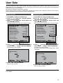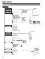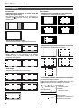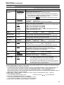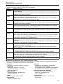
1
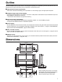
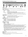
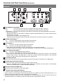
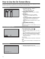
cev.fr
Operating Instructions
LCD Video Monitor
BT-
P
Model No. BT-
E
Before operating this product, please read the instructions carefully and save this manual for future use.
S0506M0 -H D
Printed in Japan
ENGLISH
VQT0X79
Precautions for Use
• The liquid crystal portion is manufactured with highly precise technology. It includes over 99.99% effective pixels,
but 0.01% or less of the pixels are either missing, or have fixed lighting (red, blue, green). This is not a sign of
malfunction.
• The liquid crystal protection panel is a specially manufactured component. Wiping it with a hard cloth, or rubbing
it vigorously will scratch the surface.
• If a still image is displayed for a long time, it may cause temporary generation of afterimage (phosphor burn-in).
(However, these afterimages disappear when ordinary moving images are displayed for a while.)
• The response speed and brightness of liquid crystal vary with ambient temperatures.
• Do not install the unit in a place exposed to the direct sunlight. It may otherwise deteriorate the cabinet or
damage the liquid crystal screen.
• The unit is not compatible with the VESA mount.
• When installing, keep the display 10 cm (4 inches) or more away from the back wall and surrounding objects.
Contents
Read this first ! (for BT-LH2600WP) . . . . . . . . . . . . . 2
Read this first ! (for BT-LH2600WE) . . . . . . . . . . . . . 4
Precautions for Use . . . . . . . . . . . . . . . . . . . . . . . . . 6
Standard accessories . . . . . . . . . . . . . . . . . . . . . . . 6
Outline . . . . . . . . . . . . . . . . . . . . . . . . . . . . . . . . . . . . 7
Dimensions . . . . . . . . . . . . . . . . . . . . . . . . . . . . . . . . 7
Controls and Their Functions . . . . . . . . . . . . . . . . . 8
Video monitor unit ................................................... 8
Front panel .............................................................. 9
Rear panel............................................................. 10
Power Supply. . . . . . . . . . . . . . . . . . . . . . . . . . . . . . 11
How to Use the On Screen Menu . . . . . . . . . . . . . . 12
User Data . . . . . . . . . . . . . . . . . . . . . . . . . . . . . . . . . 15
Main Menu . . . . . . . . . . . . . . . . . . . . . . . . . . . . . . . . 16
Menu configuration................................................ 16
MARKER............................................................... 17
Standard accessories
(For BT-LH2600WP)
Power cord x 1
Power cord hook x 1
Screw x 1
(For BT-LH2600WE)
AC mains lead x 2
AC mains lead hook x 1
Screw x 1
6
Types of MARKER................................................. 18
VIDEO CONFIG .................................................... 19
SYSTEM CONFIG................................................. 21
FUNCTION............................................................ 22
GPI ........................................................................ 26
INPUT SELECT..................................................... 27
AUDIO ................................................................... 28
CONTROL............................................................. 29
HOURMETER ....................................................... 29
REMOTE Specifications . . . . . . . . . . . . . . . . . . . . . 30
Error/Warning Displays. . . . . . . . . . . . . . . . . . . . . . 34
Maintenance. . . . . . . . . . . . . . . . . . . . . . . . . . . . . . . 34
Maintenance Inspections . . . . . . . . . . . . . . . . . . . . 34
Specifications . . . . . . . . . . . . . . . . . . . . . . . . . . . . . 35
Outline
The BT-LH2600W liquid crystal monitor was designed especially for broadcasting service and business use. It is
equipped with a high performance 26-inch wide liquid crystal display panel.
g High performance liquid crystal panel
This monitor achieves outstanding color reproduction, a wide viewing angle, and high-speed response.
g Immediate image output of input signals
Time lag per field caused by IP conversion*1 peculiar to LCD panels is eliminated. The period between input and
picture display is reduced to a minimum.
*1 Conversion from interlace to progressive scanning.
g Multi-format image compatability
• This monitor is equipped with SDI (HD/SD compatible), VIDEO, Y/C, YPBPR/RGB input jacks.
• It supports both NTSC and PAL TV broadcast systems.
g Screen display
You can divide the screen into two windows, and compare the windows using the same input terminal and same
format. Furthermore, you can display a still image or WFM on one of the windows (J page 21 “SUB WINDOW”,
page 24 “About the SUB WINDOW”, page 25 “About WFM”).
g PIXEL TO PIXEL function
You can use the actual pixel count for picture confirmation when the input is an HD signals (J page 25 “About
PIXEL TO PIXEL and PIXEL POS.”).
g REMOTE control
Depending on the intended use of the monitor, you can select between parallel remote control (GPI) and serial
remote control (RS-232C) (J page 30 – 33).
Dimensions
Unit : mm (inches)
450 (17-3/4)
250 (9-7/8)
5
6- Ø
40.5 (1-5/8)
236.5 (9-3/8)
251 (9-7/8)
575.8 (22-3/4) (Display area)
323.7 (12-3/4) (Display area)
50.5 (2)
663 (26-3/32)
199 (7-7/8)
114 (4-1/2) 105.5 (4 -1/8)
270 (10-5/8)
213 (8-3/8)
4.5 (1/8)
3-M
4
27.7 (1-1/8)
456.1 (17-31/32)
441.5 (17-3/8)
430 (17)
When installing the monitor in one place
permanently, we recommend that you fix
the monitor in place using the screw
holes in the lower part of the stand.
7
Controls and Their Functions
Video monitor unit
Front view
Tally (J page 26, 30)
Front panel (J page 9)
Rear view
Fan (J page 21)
Rear panel (J page 10)
8
Power supply (J page 11)
Controls and Their Functions (continued)
Front panel
POWER
VIDEO
Y/C
SDI 1
INPUT SELECT
SDI 2
YPBPR/
RGB
MENU
FUNCTION
ENTER
1
2
3
4
5
PHASE CHROMA BRIGHT CONTRAST/ VOLUME
BACKLIGHT
POWER switch
This switches the power supply ON/OFF. When the power is ON, the LED (green) lights up.
INPUT SELECT button
This selects the signal input line. The green LED light above the button indicates the selected input signal.
VIDEO
: Video input
Y/C
: Y/C input
SDI1
: Serial digital interface input (HD/SD compatible)
SDI2
: Serial digital interface input (HD/SD compatible)
YPBPR/RGB : Analog component (YPBPR) or RGB input. Also compatible with PC input RGB.
* When using PC Input, select “RGB-COMP.” from “YPBPR/RGB” in the “INPUT SELECT”
menu (Jpage 27).
* The monitor retains the input signal settings selected from the last time the monitor was swiched ON or OFF.
MENU button
This is used for menu display, selecting settings, and adjustments.
MENU
: Push to display or exit the menu, and to return to the previous menu screen.
,
: Push to move the cursor up or down, or to select an item.
ENTER
: Push to confirm a setting, and to display a submenu.
FUNCTION button
FUNCTION 1 : Carries out the item selected in the menu.
FUNCTION 2 : Carries out the item selected in the menu.
FUNCTION 3 : Carries out the item selected in the menu.
FUNCTION 4 : Carries out the item selected in the menu.
FUNCTION 5 : Carries out the item selected in the menu.
Picture adjusting knob
PHASE
0 – 60 (30)
CHROMA
0 – 60 (30)
BRIGHT
0 – 60 (30)
CONTRAST 0 – 60 (50)/BACKLIGHT 0 – 60 (60)
( ) denotes factory preset values
A rotating knob that can be pushed to operate. When the picture adjusting knob is pressed, its status is
displayed and adjustment becomes possible. The setting values are saved by pushing the knob again.
When values are changed from the factory preset values, the LED above the knob (amber) lights.
The setting values are loaded when the monitor’s power is switched ON. The setting values are saved when
the knob is pushed, or when 10 seconds pass after changing the settings. However, operating changes
cannot be made in the following cases.
* When the control lock is on, the key mark appears and setting values cannot be changed (J page 29).
* Only items selected in the menu can be adjusted with [CONTRAST] and [BACKLIGHT] (J page 21).
* When the MONO function is ON (J page 19), [PHASE] and [CHROMA] operations are disabled.
* When using “RGB-COMP.” input, [PHASE] and [CHROMA] operations are disabled.
* While operating HV DELAY (J page 24) (when set to any other setting than OFF), [BRIGHT] operation is
disabled.
Volume knob
You can adjust the speaker volume by rotating the volume knob.
Speaker
Audio input from the AUDIO input terminal or SDI terminal (embedded audio) can be heard.
Audio output setting is in the menu.
9
Controls and Their Functions (continued)
Rear panel
1
2
3
6
4
7
5
8
SDI (HD/SD) terminal (BNC)
IN1
: This is the SDI input terminal (compatible with HD/SD automatic switching).
IN2
: This is the SDI input terminal (compatible with HD/SD automatic switching).
SWITCHED OUT : This is the active through-out terminal for the SDI input signal being displayed on the screen.
* SDI active through-out
Signal output results only when [SDI1] or [SDI2] is selected in [INPUT SELECT]. No output results when the
selected input is not SDI.
The terminal is compatible with embedded audio.
Outputting signals received through the SDI input terminals and converted to analog is not possible.
VIDEO terminal (BNC)*1*2
IN
: This is the VIDEO signal (composite signal) input terminal.
OUT : This is the composite input signal through-out terminal.
Y/C terminal*1*2
IN
: This is the Y/C signal (S-video signal) input terminal.
OUT : This is the Y/C input signal through-out terminal.
* Wide display (16:9) information from the input signal is not automatically detected.
Change the aspect ratio settings, referring to SD ASPECT (J page 19) on the VIDEO CONFIG Menu.
YPBPR/RGB terminal (BNC)*1*2
IN
: This is the YPBPR/RGB signal input terminal.
OUT : This is the YPBPR/RGB input signal through-out terminal.
* When using the RGB signal, you can also connect the external synchronizing signal to the SYNC/HD
terminal. When using a PC RGB signal, connect the horizontal synchronizing signal to the SYNC/HD
terminal, and the vertical synchronizing signal to the VD terminal.
VD IN input terminal
This is the vertical synchronizing signal (VD) input terminal used when connecting to a PC RGB signal.
AUDIO input terminal (Pin terminal)
This is the common audio input terminal for all video input terminals.
* When an embedded audio unit BT-YAE1700G (optional) is attached, SDI input audio is automatically
selected by selecting [SDI1] or [SDI2] with [INPUT SELECT].
GPI input terminal (D-SUB 9-pin)
External control is possible by using a GPI signal.
RS-232C input terminal (D-SUB 9-pin)
External control is possible by using a RS-232C signal.
*1 When a cable is not connected to the through-out terminal, the VIDEO IN terminal automatically bears 75 Ω
resistance. When the cable is connected, 75 Ω resistance is removed.
*2 When the through-out terminal is used, depending on connected equipment, the unit's picture level may be
exceeded because 75 Ω resistance at the end of the terminal is automatically removed.
10
Power Supply
Connecting and fixing the power cord (for the U.S.A. and Canada)
1. Attach the power cord to the monitor unit.
2. Connect the power cord to the power outlet.
Using the power cord
hook and the screw,
attach the power cord to
the monitor unit.
Power cord
Power cord hook
Screw
Connecting and fixing the AC mains lead (for others)
1. Attach the mains lead to the monitor unit.
2. Connect the AC mains lead to the power outlet.
Using the AC mains lead
hook and the screw,
attach the AC mains lead
to the monitor unit.
AC mains lead
AC mains lead hook
Screw
11
How to Use the On Screen Menu
Six types of information are displayed on the screen. The input signal status, picture adjusting knob status,
sharpness display, function display, audio level meter display and the menu display.
Input signal status
SDI1
1
2
3 4
1. The selected input line (J page 9, )
• VIDEO, Y/C, SDI1, SDI2,
YPBPR/RGB-VIDEO/RGB-COMP.
2. Various display (FILM mode)
• Displayed when “FILM” is selected in “GAMMA
SELECT”.
3. Signal format
• The display status can be set in “STATUS
DISPLAY” in the “SYSTEM CONFIG” menu
(J page 21).
• If “UNSUPPORT SIGNAL” is displayed, then either
the current input signal is not supported or the
“INPUT SELECT” menu setting needs to be
changed.
• When “NO SIGNAL” is displayed, there is no input
signal.
4. Various display (lock setting)
• Displayed when control lock is ON.
Note:
“UNSUPPORT SIGNAL” and “NO SIGNAL” may not be
displayed correctly.
Picture adjusting knob status
Picture adjusting knob (J page 9, )
• This knob can be rotated and pushed.
• The status display appears when the knob is
pushed.
The display disappears when the knob is pushed
again, or if the knob is not operated for 10 seconds.
• Settings can only be adjusted in the status display.
• The display position can be changed (J page 21
“ROTARY POSITION”).
Status display:
PHASE, CHROMA, BRIGHT, CONTRAST or BACKLIGHT
Note:
The volume knob status display is not displayed on the
screen.
Sharpness display
• Sharpness is displayed when it is set.
• The display disappears if remains idle for 2 minutes.
SHARPNESS
12
30
How to Use the On Screen Menu (continued)
Function display
• You can set FUNCTION display in the menu.
• When “FUNCTION DISPLAY” (J page 22) is “ON”
and either [FUNCTION1] or [FUNCTION5] is
pressed, the unit displays the status of the
FUNCTION item set.
• The display disappears if remains idle for 2 seconds.
• The operational status is displayed in “XXXXX” (J
page 23 “Operation items displayed when a
FUNCTION button is used”).
F1:MARKER
F2:WFM
F3:LEVEL METER
F4:PIXEL TO PIXEL
F5:PIXEL POS.
XXXXX
Audio level meter display
1
3
5
7
2
4
6
8
Channel
display
Level
display
• When the signal is SDI, the audio level is displayed
on the white skeleton bar meter.
• You can switch the level display on and off, and set
the number of displayed channels using the menu.
• The 0 dB line and channel display can be switched
on and off from the menu.
0 dB
line
Menu display
[MAIN MENU]
• This is displayed when the menu is used.
• The display disappears if remains idle for 2 minutes.
• The display position can be changed (J page 21
“MENU POSITION”).
FUNCTION
HOURMETER
MENU
Displays the operation explanation for the
menu button.
13
How to Use the On Screen Menu (continued)
Menu operations
1. Push [MENU] to display the MAIN menu.
3. Push [ ,
] to select the sub menu, then push
[ENTER].
The setting values in the sub menu change to green.
MARKER
MARKER
16:9
4:3
BACK
CENTER
GPI PRESET1
GPI PRESET2
2. Push [ ,
[ENTER].
] to select the menu, then push
[MAIN MENU]
FUNCTION
HOURMETER
MENU
To return to the previous screen
Push [MENU].
14
OFF
OFF
OFF
NORMAL
OFF
4:3
4:3
SET
4. Push [ ,
] to select the setting values, then
push [ENTER].
Push [MENU] to cancel.
MARKER
MARKER
16:9
4:3
BACK
MARKER
GPI PRESET1
GPI PRESET2
ON
OFF
OFF
NORMAL
OFF
4:3
4:3
SET
User Data
You can change the menu setting values and picture adjusting knob settings, then save and load up to 5
combinations of screen adjustment values as user data. You can also return the setting values and adjustment
values to the factory preset settings.
The following settings are included in user data.
• Menu settings except for “SETUP LOAD/SAVE” (including the button function settings on the front of the monitor)
• Screen adjustment values changed in picture adjusting knob
Saving user data
Loading user data
1. Push [MENU] to display the MAIN menu.
2. Push [ ,
] to select the “SYSTEM CONFIG”
menu and push [ENTER].
3. Push [ ,
] to select the “SETUP SAVE” sub
menu and push [ENTER].
The setting values in the sub menu change to green.
1. Push [MENU] to display the MAIN menu.
2. Push [ ,
] to select the “SYSTEM CONFIG”
menu and push [ENTER].
3. Push [ ,
] to select the “SETUP LOAD” sub
menu and push [ENTER].
The setting values in the sub menu change to green.
CONT./BACK.
BACKLIGHT
SUB WINDOW
WFM POSITION
MENU POSITION
ROTARY POSITION
STATUS DISPLAY
SETUP LOAD
SETUP SAVE
FAN MOTOR
COLOR SPACE
BACKLIGHT
60
FULL
RB
CENTER
LB
3SEC OFF
FACTORY
USER1
OFF
EBU
CONT./BACK.
BACKLIGHT
SUB WINDOW
WFM POSITION
MENU POSITION
ROTARY POSITION
STATUS DISPLAY
SETUP LOAD
SETUP SAVE
FAN MOTOR
COLOR SPACE
Changes to green
4. Push [ ,
] to select the file you wish to save
to from “USER1” – “USER5”, then push [ENTER].
The following screen appears.
BACKLIGHT
60
FULL
RB
CENTER
LB
3SEC OFF
FACTORY
USER1
OFF
EBU
Changes to green
4. Push [ , ] to select the file you wish to load to
from “USER1” – “USER5”, then push [ENTER].
The following screen appears.
To return to the factory preset setting values, select
“FACTORY”.
SETUP SAVE
SETUP LOAD
5. Select “YES”, and push [ENTER].
The user data is saved.
5. Select “YES”, and push [ENTER].
The user data is loaded.
To return to the previous screen
Push [MENU].
15
Main Menu
Menu configuration
MAIN MENU
MARKER
MARKER
VIDEO CONFIG
SYSTEM CONFIG
FUNCTION
16:9
GAMMA SELECT
CONT./BACK.
FILM GAMMA
BACKLIGHT
COLOR TEMP.
SUB WINDOW
SHARPNESS MODE
WFM POSITION
SHARPNESS H
MENU POSITION
SHARPNESS V
ROTARY POSITION
I-P MODE
STATUS DISPLAY
MONO
SETUP LOAD
ANAMO
SETUP SAVE
SD ASPECT
FAN MOTOR
SCAN
COLOR SPACE
NOISE WIPE
4:3
BACK
CENTER
GPI PRESET1
GPI PRESET2
USER0-63
D93
D65
D56
VAR1
VAR2
VAR3
FUNCTION1
FUNCTION2
FUNCTION3
FUNCTION4
FUNCTION5
FUNCTION DISPLAY
GPI CONTROL
GPI
INPUT SELECT
GPI1
GPI2
VIDEO/ Y/C
GPI3
NTSC SETUP
GPI4
YPBPR/RGB
GPI5
COMPONENT LEVEL
GPI6
RGB SYNC
COMP.
AUDIO
INPUT SELECT
EMBEDDED SELECT L
EMBEDDED SELECT R
LEVEL METER
0 dB POINT
AUTOSETUP
H POSITION
GPI7
GPI8
V POSITION
PHASE
CLOCK
WXGA/XGA
COLOR TEMP.
CH
CONTROL
GAIN RED
CONTROL
GAIN GREEN
LOCAL ENA.
*[WHITE BALANCE VAR1-3]
HOURMETER
GAIN BLUE
OPERATION
BIAS RED
LCD
BIAS GREEN
FAN
BIAS BLUE
RESET
16
Main Menu (continued)
MARKER
The underlined values are factory preset setting values.
Sub menu
MARKER
16:9*2*3
4:3*2*4
Settings
*1
Explanation
<OFF>
<ON >
Used to make MARKER settings effective.
<OFF>
<4:3 >
<13:9>
<14:9>
<CNSCO>
<VISTA>
<95%>
<93%>
<90%>
<88%>
<80%>
Used to select/display the type of marker when the aspect ratio
setting is 16:9.
<OFF>
<95%>
<93%>
<90%>
<88%>
<80%>
<OFF>
<4:3>
<14:9>
<VISTA>
<93%>
<88%>
Marker not displayed.
4:3 marker
14:9 marker
VISTA marker
93% Area marker
88% Area marker
<13:9>
<CNSCO>
<95%>
<90%>
<80%>
13:9 marker
CNSCO marker
95% Area marker
90% Area marker
80% Area marker
Used to select/display the type of marker when the aspect ratio
setting is 4:3.
<OFF>
<95%>
<90%>
<80%>
Marker not displayed.
95% Area marker
90% Area marker
80% Area marker
<93%>
<88%>
93% Area marker
88% Area marker
BACK*2
<NORMAL>
<HALF>
<BLACK>
Used to select the background brightness excluding the marker.
<NORMAL>
Normal background
<HALF>
Background brightness 50%
<BLACK>
Background brightness 0% (Black)
CENTER*2
<OFF>
<ON>
Used to display the center marker.
<OFF>
Not displayed
<ON>
Displayed
GPI PRESET1*5
<4:3>
<13:9>
<14:9>
<CNSCO>
<VISTA>
<95% (16:9)>
<93% (16:9)>
<90% (16:9)>
<88% (16:9)>
<80% (16:9)>
<95% (4:3)>
<93% (4:3)>
<90% (4:3)>
<88% (4:3)>
<80% (4:3)>
GPI PRESET1: Used to select the marker to be displayed using the
GPI terminal “MARKER1 ON/OFF” operation (J page 30).
GPI PRESET2*5
GPI PRESET2: Used to select the marker to be displayed using the
GPI terminal “MARKER2 ON/OFF” operation (J page 30).
<4:3>
4:3 marker
<13:9> 13:9 marker
<14:9> 14:9 marker
<CNSCO> CNSCO marker
<VISTA> VISTA marker
<95% (16:9)> 95% Area marker when the aspect ratio is 16:9.
<93% (16:9)> 93% Area marker when the aspect ratio is 16:9.
<90% (16:9)> 90% Area marker when the aspect ratio is 16:9.
<88% (16:9)> 88% Area marker when the aspect ratio is 16:9.
<80% (16:9)> 80% Area marker when the aspect ratio is 16:9.
<95% (4:3)> 95% Area marker when the aspect ratio is 4:3.
<93% (4:3)> 93% Area marker when the aspect ratio is 4:3.
<90% (4:3)> 90% Area marker when the aspect ratio is 4:3.
<88% (4:3)> 88% Area marker when the aspect ratio is 4:3.
<80% (4:3)> 80% Area marker when the aspect ratio is 4:3.
*1 The setting becomes “On” when the unit receives marker-related control during REMOTE operation. (Priority
goes to GPI when GPI settings exist.)
*2 When controlling the marker settings using the GPI function (J page 30), these settings become disabled.
These are not operated when the 2 screens are displayed.
*3 These are only enabled when the HD signal and SD signal aspect ratio settings are 16:9.
*4 These are only enabled when the SD signal aspect ratio setting is 4:3.
*5 When setting “GPI PRESET1” or “GPI PRESET2” using GPI function, the REMOTE function depending RC232C becomes disabled (error response: ER001).
17
Main Menu (continued)
Types of MARKER
g 16:9 marker
(Displayed when using HD, or when using SD
with a 16:9 aspect ratio)
The marker is only displayed as a vertical bar. In
addition, the
section becomes the “MARKER
BACK” item.
4:3 marker
g 4:3 marker
(Displayed when using SD with a 4:3 aspect ratio)
A dotted line is displayed as the marker.
95% Area marker
93% Area marker
90% Area marker
88% Area marker
13:9 marker
14:9 marker
VISTA marker, CNSCO marker
A horizontal dotted line is displayed as the marker.
80% Area marker
(Displayed when using HD, or when using SD with a 16:9 aspect ratio)
A dotted line is displayed as the marker.
VISTA marker
CNSCO marker
When “UNDER” is set in “SCAN” in the “VIDEO
CONFIG” menu, a vertical dotted line is also
displayed as the marker.
VISTA marker
CNSCO marker
95% Area marker
93% Area marker
90% Area marker
88% Area marker
Area marker
A dotted line is displayed as the marker.
80% Area marker
95% Area marker
93% Area marker
*You can display 4:3 marker at the same time as 16:9 marker.
Simultaneously display example
The
section becomes the “MARKER BACK” item. The
background selected with the 16:9 marker is controlled.
80% Area marker
90% Area marker
88% Area marker
95% Area marker
16:9 marker:
95% Area marker
4:3 marker:
80% Area marker
g Center marker
80% Area marker
18
Center marker
The marker is displayed in
the center of the picture.
Main Menu (continued)
VIDEO CONFIG
The underlined values are factory preset setting values.
Sub menu
GAMMA
SELECT*1*2
Settings
Explanation
<STANDARD>
<FILM>
<STDIO/PST>
Used to select the gamma curve.
<STANDARD>Standard mode <FILM>FILM mode
<STDIO/PST>Color emphasis mode (in the gamma characteristic in
which shades are valued more than the contrasts, it is suitable for
use by the studio and the post production, etc. )
When FILM is selected,
mark is displayed in the top left of the screen.
FILM GAMMA*2
<VARICAM>
<OTHER>
Used to select the type of FILM gamma mode.
<VARICAM> VARICAM use
<OTHER>
When using other types than VARICAM
COLOR TEMP.
<USER0–63>*5
<D93>
<D65>
<D56>
<VAR1>
<VAR2>
<VAR3>
Used to select the color temperature.
<USER0–63> Adjustable settings 0–63 (color temperature around 3000K–9300K)
<D93> Color temperature around 9300K
<D65> Color temperature around 6500K
<D56> Color temperature around 5600K
<VAR1> WB adjustment mode*4
<VAR2> WB adjustment mode*4
*4
<VAR3> WB adjustment mode
SHARPNESS
MODE*2
<HIGH>*3
<LOW>
Used to select the width of the sharpness edge.
<HIGH>
Thin edge
<LOW>
Thick edge
SHARPNESS H*2
<0–30> *3
Used to set the sharpness in the horizontal direction.
When adjusting, the item display moves to the lower part of the screen.
SHARPNESS V*2
<0–30> *3
Used to set the sharpness in the vertical direction.
When adjusting, the item display moves to the lower part of the screen.
I-P MODE*2*6
<MODE2>
<MODE1>
Used to set the mode for IP change.
<MODE2>
Within Field
<MODE1>
MONO*2
<OFF>
<ON>
Used to switch between color and monochrome (MONO).
<OFF> Color
<ON>
Monochrome
* When this is ON, the picture adjusting knob [CHROMA] setting is fixed at 0.
ANAMO*2*7
<OFF>
<ON>
If an Anamo lens has been used on the camera, and input through
SDI 720/60P, 59.94P, the picture is resized to Anamo size
magnification. (a vertically compressed signal can be amplified
vertically and corrected when it is displayed.)
SD ASPECT*2
<4:3>
<16:9>
Used for setting the aspect ratio settings when using SD signal input.
<4:3> 4:3 display
<16:9> 16:9 display
SCAN*2
<NORMAL>
<UNDER>
Used to set under-scan and normal display.
<NORMAL>Normal display
<UNDER>Under-scan
NOISE WIPE*2
<OFF>
<ON>
<OFF> This makes a fluid and smooth contrast obtainable.
This is especially effective for continuously changing the contrast of
the source signal or CG signal when the S/N is very high.
<ON> Noise reduction mode. Depending on the camera, this mode can
be especially effective for dark scenes. We recommend leaving
this setting “ON” under normal conditions.
Normal mode
*1 During 2 screen display, the changes are not reflected in the still image of the main window.
*2 When “RGB-COMP.” is selected in “YPBPR/RGB” in the “INPUT SELECT” menu (J page 27), this does not operate.
*3 The following sharpness values can each be set,
1) VIDEO system input line (VIDEO,Y/C)(Factory settings are SHARPNESS MODE : LOW, SHARPNESS H/V : 0)
2) any other input line’s HD (Factory settings are SHARPNESS MODE : HIGH, SHARPNESS H/V : 0)
3) any other input line’s SD (Factory settings are SHARPNESS MODE : LOW, SHARPNESS H/V : 0)
and the setting values for the selected input signal from within this group is displayed. The adjustment status is
displayed in the bottom right when selected.
*4 When “VAR1”, “VAR2” or “VAR3” is selected, the monitor switches to WB adjustment mode (J page 20).
*5 When selecting USER0–63
1) Push [ENTER] (USER changes to blue).
2) Select 0–63 with [ , ], and push [ENTER].
*6 When using “SUB WINDOW” function (J page 24),
1) change the setting after releasing “SUB WINDOW” function.
2) we recommand “MODE2” for the image with a fast movement.
*7 During Anamo size display, “SCAN” change is not reflected.
19
Main Menu (continued)
3
g WB adjustment mode
You can adjust “WHITE BALANCE VAR1” – “WHITE BALANCE VAR3” (WB) by selecting “VAR1” – “VAR3” in
“COLOR TEMP.” in the “VIDEO CONFIG” menu.
The underlined values are factory preset setting values.
Sub menu
Settings
*1
Explanation
COLOR TEMP.
<USER0–63>
<D93>
<D65>
<D56>
Used to select the color temperature that will become the
basis for adjustments.
<USER0–63>
Adjustable settings 0–63 (color
temperature around 3000K–9300K)
<D93> Color temperature around 9300K
<D65> Color temperature around 6500K
<D56> Color temperature around 5600K
GAIN RED
<0–511>
(Factory presets are values
for color temperature <D65>.)
* The presets are values
adjusted before shipment
from factories.
GAIN elements for RED are adjusted.*2
<-512–511>
(Factory preset settings: 0)
BIAS elements for RED are adjusted.*2
GAIN GREEN
GAIN BLUE
BIAS RED
BIAS GREEN
BIAS BLUE
RESET
GAIN elements for GREEN are adjusted.*2
GAIN elements for BLUE are adjusted.*2
BIAS elements for GREEN are adjusted.*2
BIAS elements for BLUE are adjusted.*2
“GAIN RED” – “BIAS BLUE” values are reset to color
temperatures values selected in “COLOR TEMP.”.
*1 When “COLOR TEMP.” is selected and [ENTER] is pressed following item change, the display changes to the
confirmation screen. Selecting “YES” and pressing [ENTER] on this screen return GAIN and BIAS values to the
selected color temperature values.
*2 When adjusting, the item display moves to the lower part of the screen.
20
Main Menu (continued)
SYSTEM CONFIG
The underlined values are factory preset setting values.
Sub menu
CONT./BACK.
Settings
Explanation
<CONTRAST>
<BACKLIGHT>
Used to select the function to be assigned to [CONTRAST/
BACKLIGHT] (a knob on the front panel).
<CONTRAST>
Used to adjust CONTRAST.
<BACKLIGHT>
Used to adjust BACKLIGHT.
BACKLIGHT
< 0-60 >
Used to adjust the LCD backlight level.
SUB WINDOW
<FULL>
<PART>
Used to select the type of sub window.
<FULL>
Used to reduce the whole input signal screen, and arrange it
horizontally when it is displayed.
<PART>
Used to cut out the central section of the input signal screen, and
arrange it horizontally when it is displayed (Displayed at the same size
as the previous screen).
WFM POSITION
<LB>
<RB>
<RT>
<LT>
Used to set the WFM display position.
<LB> Bottom left of the screen <RB> Bottom right of the screen
<RT> Top right of the screen
<LT> Top left of the screen
MENU
POSITION
<CENTER>
<LB>
<RB>
<RT>
<LT>
Used to set the on screen menu display position.
<CENTER> Center of the screen
<LB> Bottom left of the screen <RB> Bottom right of the screen
<RT> Top right of the screen
<LT> Top left of the screen
ROTARY
POSITION
<CENTER>
<LB>
<RB>
<RT>
<LT>
Used to set the picture adjusting knob status (on screen menu) display
position.
<CENTER> Center of the screen
<LB> Bottom left of the screen <RB> Bottom right of the screen
<RT> Top right of the screen
<LT> Top left of the screen
STATUS DISPLAY
<CONTINUE>
<3SEC OFF>
<OFF>
Used to set the input signal status (on screen menu) display status.
<CONTINUE> Displayed normally.
<3SEC OFF> After changing status, it is displayed for approximately
3 seconds, and then disappears.
<OFF>
Not displayed.
SETUP LOAD
<FACTORY>
<USER1> *1
<USER2> *1
<USER3> *1
<USER4> *1
<USER5> *1
The saved factory preset setting values (FACTORY) or the user data
(USER 1–USER 5) are loaded. Also after loading user data, the screen
displays the signal selected before loading data.
SETUP SAVE
<USER1>
<USER2>
<USER3>
<USER4>
<USER5>
Up to 5 sets of user data can be saved (J page 15).
The menu settings and picture adjusting knob adjustment values
(PHASE /CHROMA /BRIGHT /CONTRAST) excluding “SETUP SAVE/
SETUP LOAD” are saved.
FAN MOTOR
<OFF>
<ON>
Used to set fan operation.
<OFF>
The fan is stopped. The brightness of the backlight
automatically lowers.
<ON>
The fan operates. The backlight brightness returns to
normal.
COLOR SPACE
<EBU>*2
<SMPTE-C>*2
Used to set studio-specified colors.
*1 When the monitor is shipped from the factory, “USER1” – “USER5” and “FACTORY” all have the same details.
*2 Factory preset settings are The U.S.A. and Canada: SMPTE-C, Others: EBU.
21
Main Menu (continued)
FUNCTION
The underlined values are factory preset setting values.
Sub menu
FUNCTION 1 –
FUNCTION 5
Settings
<HV DELAY>
<AUTOSETUP>
<BLUE ONLY>
<GAMMA SELECT>
<SD ASPECT>
<SCAN>
<SUB WINDOW>
<WFM>
<MARKER>
<PIXEL TO PIXEL>
<PIXEL POS.>
<LEVEL METER>
<MONO>
<UNDEF>
(Factory preset
settings
FUNCTION1:
MARKER
FUNCTION2:
WFM
FUNCTION3:
LEVEL METER
FUNCTION4:
PIXEL TO PIXEL
FUNCTION5:
PIXEL POS.)
FUNCTION DISPLAY
<ON>
<OFF>
Explanation
Used to select the functions to be assigned to individual
buttons [FUNCTION1] to [FUNCTION5] (front-panel buttons).
<HV DELAY>
Displays the synchronizing signal (horizontal, vertical).
The display is switched in the following order.
DELAY OFF J V DELAY J H DELAY J HV DELAY J
DELAY OFF
<AUTOSETUP>
Used to automatically adjust the PC display.
<BLUE ONLY>
Used to cut the red and green signals. You can check the hue
(PHASE) and depth of color (CHROMA). This is switched
between ON/OFF by pushing the button.
<GAMMA SELECT>
Used to display the gamma curve.
The display changes in the following order.
GAMMA STANDARD J GAMMA FILM J
GAMMA STDIO/PST J GAMMA STANDARD
<SD ASPECT>
Used to switch between “16:9” and “4:3”.*1
<SCAN>
You can switch between “UNDER SCAN” and “NORMAL
SCAN”.*1
<SUB WINDOW>
You can perform the settings for 2 screen display mode.*1
The display changes in the following order.
SINGLE J FULL/PARTJ STILLJ SINGLE
<WFM>
Used to display the wave form monitor.
<MARKER>
Used to switch the marker on and off.
<PIXEL TO PIXEL>
Used to switch the display between the input size and display
size.
<PIXEL POS.>
Used to set the signal display position when PIXEL TO PIXEL
is on.
<LEVEL METER>
Used to switch the AUDIOMETER display.
The display changes in the following order.
METER 8CH J METER 4CH J METER 2CH J OFFJ
METER 8CH
<MONO>
Used to switch the display between color and black-andwhite.
<UNDEF>
No settings
Used to make display settings for the functions assigned to
individual buttons [FUNCTION1] to [FUNCTION5] (frontpanel buttons).
<ON>
The selected function is displayed.
<OFF>
The selected function is not displayed.
*1 If these settings are changed, the menu settings will also change.
22
Main Menu (continued)
g Restrictions on various FUNCTION settings
Under the following conditions, various settings are disabled.
Setting
HV DELAY
Disabling condition
In SUB WINDOW, WFM or PIXEL TO PIXEL mode, “INVALID FUNCTION” is displayed and the
setting is disabled.
When “YPBPR/RGB” set in “INPUT SELECT” menu is “RGB-COMP.”, “INVALID FUNCTION” is
displayed and the setting is disabled.
AUTO
SETUP
When “YPBPR/RGB” set in “INPUT SELECT” menu is other than “RGB-COMP.”, “NOT RGBCOMP. CH” is displayed and the setting is disabled.
When “YPBPR/RGB” set in “INPUT SELECT” menu is “RGB-COMP.” and there is NO SIGNAL,
“INCOMPLETE” is displayed and the setting is disabled.
GAMMA
SELECT
When GPI item is set, “INVALID FUNCTION” is displayed and the setting is disabled.
When “YPBPR/RGB” set in “INPUT SELECT” menu is “RGB-COMP.”, “INVALID FUNCTION” is
displayed and the setting is disabled.
SD ASPECT
When GPI item is set, “INVALID FUNCTION” is displayed and the setting is disabled.
When SUB WINDOW (still picture) or HD display (including PIXEL TO PIXEL) is on, “INVALID
FUNCTION” is displayed and the setting is disabled.
SCAN
When GPI item is set, “INVALID FUNCTION” is displayed and the setting is disabled.
In SUB WINDOW or PIXEL TO PIXEL mode, “INVALID FUNCTION” is displayed and the setting
is disabled.
SUB
WINDOW
When “YPBPR/RGB” set in “INPUT SELECT“ menu is other than “RGB-COMP.”, “INVALID
FUNCTION” is displayed and the setting is disabled.
When “RGB-COMP.” is selected in SUB WINDOW with a motion picture on, the screen turns SINGLE.
When an item other than “RGB-COMP.” is selected, two motion pictures are displayed on the
screen. When a still picture is on, blackout occurs.
WFM
In SUB WINDOW or PIXEL TO PIXEL mode, “INVALID FUNCTION” is displayed and the setting
is disabled.
When “YPBPR/RGB” set in “INPUT SELECT” menu is “RGB-COMP.” or “RGB-VIDEO”, “INVALID
FUNCTION” is displayed and the setting is disabled.
MARKER
When “YPBPR/RGB” set in “INPUT SELECT” menu is “RGB-COMP.”, “INVALID FUNCTION” is
displayed and the setting is disabled.
When GPI item is set or in SUB WINDOW mode, “INVALID FUNCTION” is displayed and the
setting is disabled.
PIXEL TO
PIXEL
When “YPBPR/RGB” set in “INPUT SELECT” menu is “RGB-COMP.” or “RGB-VIDEO”, “INVALID
FUNCTION” is displayed and the setting is disabled.
In SUB WINDOW mode, “INVALID FUNCTION” is displayed and the setting is disabled.
PIXEL POS.
When PIXEL TO PIXEL is OFF, “PIXEL TO PIXEL OFF” is displayed and the setting is disabled.
When PIXEL TO PIXEL is 720P display, the position becomes CENTER.
When the display position is not CENTER in PIXEL TO PIXEL mode during 1080P display and
the 720P signal is selected, the display position moves to CENTER.
MONO
When GPI item is set, “INVALID FUNCTION” is displayed and the setting is disabled.
g Operation items displayed when a FUNCTION button is used
When any of the buttons, [FUNCTION1] to [FUNCTION5], is pressed, the following messages are displayed
according to the operation assigned to the pressed button.
• HV DELAY
DELAY OFF, V DELAY, H DELAY, HV DELAY
• AUTOSETUP
COMPLETE: Display for completion
INCOMPLETE: Display for incompletion
NOT RGB-COMP. CH
• GAMMA SELECT
GAMMA STANDARD, GAMMA FILM,
GAMMA STDIO/PST
• SCAN
NORMAL SCAN, UNDER SCAN
• SUB WINDOW
SINGLE, FULL/PART, STILL
• MARKER
MAKER OFF, 4:3 MARKER, 13:9 MARKER,
14:9 MARKER, VISTA MARKER,
CNSCO MARKER, 95% MARKER, 93% MARKER,
90% MARKER, 88% MARKER, 80% MARKER
• PIXEL TO PIXEL/PIXEL POSITION
CENTER, LEFT TOP, LEFT BOTTOM,
RIGHT TOP, RIGHT BOTTOM
PIXEL TO PIXEL OFF
• LEVEL METER
METER OFF, METER 2CH, METER 4CH,
METER 8CH
23
Main Menu (continued)
g About HV DELAY
This displays the video blanking period. By pushing the button, you can switch through the H blanking display J
V blanking display J H and V blanking display J no blanking display.
g About the SUB WINDOW
You can compare saved still and moving images by using the “SUB WINDOW” function to separate the main
window into 2 displays as shown below.
Depending on the settings of the “SUB WINDOW” (FULL, PART) in the “SYSTEM CONFIG” menu (J page 21) it
can be switched as shown below.
The display changes each time you press one of the buttons, [FUNCTION1] to [FUNCTION5] (J page 22),
assigned with the [SUB WINDOW] function. (To use the “SUB WINDOW” function, you must assign it to one of
the [FUNCTION1] to [FUNCTION5] buttons.)
When setting “I-P MODE” function (J page 19),
1)change the setting after releasing “SUB WINDOW” function.
2)we recommand “MODE2” for the image with a fast movement.
• FULL
The main window is reduced and made into 2 sub window (sub window+sub window).
Press the FUNCTION button assigned with the SUB WINDOW function.
Normal window
(main window)
Before inputting the image
(sub window+sub window)
Press the
same button
again.
moving image
After inputting the image
(sub window+sub window)
Press the
same button
again.
moving image
still image
moving image
moving image
• PART
Only the sub window size is cut out of the main window, and the cut section is made into 2 sub window images
(sub window+sub window).
Press the FUNCTION button assigned with the SUB WINDOW function.
Normal window
(main window)
Before inputting the image
(sub window+sub window)
Press the
same button
again.
moving image
The central section is cut out
After inputting the image
(sub window+sub window)
Press the
same button
again.
moving image moving image
Lines up and displays the
section cut out of the main
window
still image
moving image
The window is displayed in 16:9 aspect.
Precautions when selecting FULL/PART
This function compares screens with the same input terminal and same format. If different input formats, or if
signals are input between different input channels, the sub-window (left side, still image) becomes blurred and
blanking occurs. However, if the same format signals are input into the input terminal when acquiring the still image,
the images will be displayed correctly.
24
Main Menu (continued)
g About WFM
You can display the wave form monitor using the “WFM” function.
The display changes each time you press one of the buttons, [FUNCTION1] to [FUNCTION5] (J page 22),
assigned with the [WFM] function (To use the “WFM” function, you must assign it to one of the [FUNCTION1] to
[FUNCTION5] buttons).
Press the FUNCTION button assigned
with the WFM function once.
Normal window
WFM display
Press the
same button
again.
WFM (Wave Form Monitor)
The window is displayed in 16:9 aspect.
Restrictions on WFM
Even if “WFM” has turned ON”, “WFM” is not displayed when using the “PIXEL TO PIXEL” function, “YPBPR/RGB”
set in “INPUT SELECT” menu is “RGB-COMP.” or “RGB-VIDEO”, or using the “SUB WINDOW” function.
g About PIXEL TO PIXEL and PIXEL POS.
Using the “PIXEL TO PIXEL” function, you can confirm a picture with the actual pixel count (only when the input
is an HD signal).
First, press one of the buttons, [FUNCTION1] to [FUNCTION5] (J page 22), assigned with the “PIXEL TO
PIXEL” function to turn it “ON”. With the function on, press another one of the buttons, [FUNCTION1] to
[FUNCTION5] (J page 22), assigned with “PIXEL POS.”. Each time the button assigned with “PIXEL POS.” is
pressed, the signal display position switches. (To use the “PIXEL TO PIXEL” function, “PIXEL TO PIXEL” and
“PIXEL POS.” must be assigned to any two of the buttons, [FUNCTION1] to [FUNCTION5].)
The underlined values are factory preset setting values.
Sub menu
Settings
Explanation
PIXEL TO PIXEL*1*2
<OFF>
<ON>
Used to set the input signal size as the display size.
Compatible formats
1080/60I/59I/50I/30P/29P/25P/24P/23P/24PSF/23PSF,
720/60P/59P/50P(SDI/YPBPR)
PIXEL POS.
<CENTER>
<LEFT TOP>
<RIGHT TOP>
<RIGHT
BOTTOM>
<LEFT
BOTTOM>
Used to set the signal display position when PIXEL TO PIXEL
is on.*3
<CENTER> center
<LT>
top left
<RT>
top right
<RB>
bottom right
<LB>
bottom left
*1 When PIXEL TO PIXEL is on, the following menu settings become invalid:
“ON” for “ANAMO” and “UNDER” for “SCAN” set in “VIDEO CONFIG”
Various “HV DELAY” settings in “FUNCTION”
“MARKER display”
*2 When the input signal is “SDI1”, “SDI2” or “YPBPR”, the setting takes effect. However, 1080/60P and 1080/50P
signals are excluded.
*3 When the input signal format is 720, only CENTER is displayed.
25
Main Menu (continued)
GPI
The “GPI CONTROL” item is used to set enable/disenable of all GPI functions, and assigns functions to each of the
GPI terminal pins (J page 30).
The underlined values are factory preset setting values.
Sub menu
GPI CONTROL
GPI1–GPI8
Settings
Explanation
<DISENABLE>
<ENABLE>
GPI functions enable/disenable settings
<UNDEF>
<MARKER1 ON/OFF>
<MARKER2 ON/OFF>
<MARKER BACKHALF>
<MARKER BACKBLACK >
<CENTER MARKER>
<INPUT SEL. VIDEO>
<INPUT SEL. Y/C>
<INPUT SEL. SDI1>
<INPUT SEL. SDI2>
<INPUT SEL. YPBPR/RGB>
<SD ASPECT>
<SCAN>
<R-TALLY>
<G-TALLY>
<MONO>
<GAMMA SEL. FILM>
<GAMMA SEL. STDIO/
PST>
<RGB SYNC>
Used to set the GPI control terminal pin assign.
You can set the same items for each terminal
(refer to page 30 for details).
Note:
Please be aware that the following can not be performed.
• “SD ASPECT” operation when input signal is HD or PC
• “SCAN” operation when the input signal is PC
• “GAMMA SELECT” operation when the input signal is PC
• “RGB SYNC” operation when anything other than “RGB-VIDEO” is selected in “YPBPR/RGB” in the “INPUT
SELECT” menu
• “MONO” operation when input signal is PC
26
Main Menu (continued)
INPUT SELECT
The underlined values are factory preset setting values.
Sub menu
VIDEO / Y/C
Settings
Explanation
<AUTO>
<NTSC>
<PAL>
Used to select the input format for VIDEO and Y/C input. *1
<AUTO>
Either NTSC or PAL is automatically selected.
<NTSC>
NTSC
<PAL>
PAL
NTSC SETUP
<75>
<00>
Selects the NTSC setup level.
<75>
Select this when using with a setup signal of
7.5 IRE. (The inner parts of the monitor are set
to the 7.5 IRE setup level to suit the black level)
<00>
Select this when there is no setup level signal.
YPBPR/RGB
<YPBPR>
<RGB-VIDEO>
<RGB-COMP.>
Selects either YPBPR (Component) or RGB input mode.
Selects the YPBPR signal.
<YPBPR>
<RGB-VIDEO>Selects the video RGB signal.
<RGB-COMP.> Selects the PC RGB signal.
COMPONENT
LEVEL
<SMPTE>
<B75>
<B00>
Selects YPBPR (Component) signal input level.
<SMPTE>
When the signal level specified in SMPTE is
Chroma 100 IRE PB, PR = 0.7 Vp-p.
<B75>
Select this when connecting a betacam or
simliar devices set to 7.5 IRE. (The inner parts
of the monitor are set at 7.5 IRE setup level to
suit the black level)
<B00>
Select this when connecting a betacam or similar
devices that are not setup to the IRE level.
RGB SYNC
<G-ON>
<EXT>
Selects the SYNC when using RGB-VIDEO input.
<G-ON>
Select when a synchronizing signal is
superimposed on the G signal.
<EXT>
Select when an external synchronizing signal is
received in synchronization.
COMP.
Performs analog PC settings. (Refer to “COMP.” below)
*1 “AUTO” is set when the monitor is shipped from the factory, but if there are concerns about noise etc. from outside the
input signal, we recommend assigning specific format.
g COMP.
The following menus are switched by selecting “RGB-COMP.” in “YPBPR/RGB” in the “INPUT SELECT” menu.
The underlined values are factory preset setting values.
Sub menu
AUTOSETUP
Settings
*1
Explanation
Screen automatic adjustment is performed when “RGBCOMP.” is selected in “YPBPR/RGB” in the “INPUT SELECT”
menu. “AUTOSETUP” is performed if a different screen is
displayed, and “YES” is selected.
H POSITION
<0–60>
(Factory preset setting: 30)
Used to adjust the picture display position in the horizontal
direction. *2
V POSITION
<0–60>
(Factory preset setting: 30)
Used to adjust the picture display position in the vertical
direction. *2
PHASE
<0–31>
(Factory preset settings:
J page 28)
Used to adjust the clock phase with 1/32 clock phases. *2
CLOCK
<700–1800>
(Factory preset settings:
J page 28)
Used to adjust the sampling clock in dot units. *2
WXGA/XGA
<XGA>
<WXGA>
Switches between WXGA and XGA.
*1 “EXECUTING” is displayed while “AUTOSETUP” is being executed, and “COMPLETE” is displayed when
“AUTOSETUP” is completed.
If “AUTOSETUP” cannot be completed, “INCOMPLETE” is displayed.
*2 Each “RGB-COMP.” input compatible format can be adjusted.
27
Main Menu (continued)
g “PHASE” and “CLOCK” factory preset setting values
FORMAT
CLOCK
PHASE
640x400(70Hz)
800
18
640x480(60Hz)
800
640x480(75Hz)
640x480(85Hz)
FORMAT
CLOCK
PHASE
1024x768(60Hz)
1344
2
17
1024x768(70Hz)
1328
22
840
10
1024x768(75Hz)
1312
16
832
5
1024x768(85Hz)
1376
17
800x600(60Hz)
1056
31
1280x768(60Hz)
1728
8
800x600(75Hz)
1056
12
1280x768(75Hz)
1712
31
800x600(85Hz)
1048
29
1280x1024(60Hz)
1688
20
AUDIO
Adjusting the speaker output.
The underlined values are factory preset setting values.
Sub menu
INPUT
SELECT
Settings
Explanation
<AUTO>
<ANALOG>
Used to select speaker output.
<AUTO> When SDI input line is selected with [INPUT SELECT] on the front
panel:
embedded audio (SDI terminal)
When an input line other than SDI1 and SDI2 is selected with
[INPUT SELECT] on the front panel:
analog (AUDIO input terminal)
<ANALOG> Analog (AUDIO input terminal)
EMBEDDED
SELECT L
<CH1–CH8>
(Factory preset
setting: CH1)
Used to select the audio channel of the embedded audio outputted to the left
speaker.
EMBEDDED
SELECT R
<CH1–CH8>
(Factory preset
setting: CH2)
Used to select the audio channel of the embedded audio outputted to the
right speaker.
LEVEL
<OFF>
<8CH>
<4CH>
<2CH>
Used to select the embedded audio meter for on-screen display.
0dB POINT
<ON>
<OFF>
Used to switch the 0 dB line displayed on the meter on and off.
CH
<ON>
<OFF>
Used to switch the channel displayed on the meter on and off.
METER*1
*1 When speaker output set in “INPUT SELECT” menu is analog, the level meter does not move regardless of its
display status.
28
Main Menu (continued)
CONTROL
The underlined values are factory preset setting values.
Sub menu
CONTROL
Settings
LOCAL
ENA.*2
Explanation
<LOCAL>
<REMOTE>
Used to select the operation. (Combined control lock)
<LOCAL>
Front operation enabled
<REMOTE> Remote operation enabled (The front controls become locked)*1
<DIS.>
<INPUT>
When “REMOTE” is selected in “CONTROL”, this selects whether front
controls are enabled/disenabled.
All front operations are disabled.
<DIS.>
<INPUT>
All controls except for the [INPUT SELECT] button and
volume knob are disabled.
*1 The menu can be displayed when the lock is engaged.
The only menu setting that can be changed when the lock is engaged is the “CONTROL/LOCAL ENA.” item.
When the lock is engaged, the picture adjusting knob is disabled.
Operations when the lock is engaged follow the settings in “LOCAL ENA.”.
When the lock is engaged, the volume knob can be operated (J page 9, ).
When the lock is engaged, the key mark is displayed on the screen.
Key mark
[MAIN MENU]
MARKER
*2 This is only enabled when “CONTROL” is set to “REMOTE”.
HOURMETER
The underlined values are factory preset setting values.
Sub menu
OPERATION
Settings
Explanation
*3
Used to display the power distribution time.
*3
Used to display the backlight activation time.
<XXH>
LCD
<XXH>
FAN
<XXH>*3
Used to display the FAN operation time.*4
*3 Time is displayed in “XX”.
*4 Linked with the FAN MOTOR ON/OFF status.
29
REMOTE Specifications
REMOTE operation is possible on this monitor using the GPI/RS-232C terminal.
GPI terminal
Each of the items in the GPI screen are compatible with the following terminals.
You can assign functions to each terminal in the menu GPI screen (J page 26).
The functions assigned to each terminal operate when the GND (5 Pin) is connected (ON) or open (OFF).
g Operating conditions
Pin number
Signal
Level operation: operates when GND is connected.
1
GPI1
Edge operation: operates when GND changes from
2
GPI2
open to connected.
GPI Terminal (9P)
3
GPI3
• If you have assigned a level operation function to
more than one terminal, the function operates as long
4
GPI4
as one of the terminals is connected.
5
GND
6
GPI5
7
GPI6
8
GPI7
9
GPI8
Assignment items Function
Operating conditions
UNDEF
No settings (no terminal assignment functions)
—
MARKER1
Switches the marker display of the marker decided in
Level operation
“GPI PRESET1” (J page 17) in the “MARKER” menu.
(Connected: ON, Open: OFF)
ON/OFF*1
MARKER2
Switches the marker display of the marker decided in
Level operation
“GPI PRESET2” (J page 17) in the “MARKER” menu.
(Connected: ON, Open: OFF)
ON/OFF*1
MARKER
Reduces the brightness of the background outside the
Level operation
marker displayed in “GPI PRESET1” (J page 17) by 50%.
(Connected: ON, Open: OFF)
BACK HALF*2
MARKER
Reduces the brightness of the background outside the
Level operation
marker displayed in “GPI PRESET1” (J page 17) to 0%.
(Connected: ON, Open: OFF)
BACK BLACK*2
CENTER MARKER Switches the center marker display ON/OFF.
Level operation
(When other markers are being displayed, this is
(Connected: ON, Open: OFF)
superimposed on the other markers)
INPUT SEL. VIDEO Switches the input system to VIDEO.
Edge operation
INPUT SEL. Y/C
Switches the input system to Y/C.
Edge operation
INPUT SEL. SDI1
Switches the input system to SDI1.
Edge operation
INPUT SEL. SDI2
Switches the input system to SDI2.
Edge operation
INPUT SEL.
YPBPR/RGB
SD ASPECT
Switches the input system to YPBPR/RGB.
Edge operation
Sets the aspect ratio settings when using SD signal
input. (Disabled when using HD signal and PC signal)
Level operation
(Connected: 16:9, Open: 4:3)
SCAN
You can switch the scan mode between “UNDER”
and “NORMAL”. (Disabled when using PC signal)
Level operation (Connected: UNDER,
Open: NORMAL)
R-TALLY*3
Lights the red tally.
Level operation
(Connected: ON, Open: OFF)
G-TALLY*3
Lights the green tally.
Level operation
(Connected: ON, Open: OFF)
MONO
Switches between color and monochrome
(MONO). (Disabled when using PC signal)
Level operation (Connected:
Monochrome, Open: Color)
GAMMA SEL. FILM
Used to switch the gamma characteristic to the
FILM mode.
Level operation (Connected: FILM
mode, Open: STANDARD mode)
GAMMA SEL.
STDIO/PST
Used to switch the gamma characteristic to the
STDIO/PST mode.
Level operation (Connected: STDIO/
PST mode, Open: STANDARD mode)
RGB SYNC*4
Used to select SYNC at the time of RGB-VIDEO
input.
Level operation
(Connected: EXT, Open: G-ON)
*1 When the 16:9 marker and 4:3 marker are simultaneously selected and activated on the 16:9 aspect display, both markers are displayed.
*2 When the 16:9 marker and 4:3 marker are simultaneously displayed, the background selected with the 16:9 marker is controlled.
*3 When both “R-TALLY” and “G-TALLY” are ON at the same time, the tally color becomes orange.
*4 This is only enabled when “RGB-VIDEO” is selected in “YPBPR/RGB” in the “INPUT SELECT” menu.
30
REMOTE Specifications (continued)
g Assignment of item priority levels
• When both “MARKER1” and “MARKER2” are ON at the same time, “MARKER1” has priority. However, when the
display aspect is 4:3, the “MARKER1” aspect is 16:9, and the “MARKER2” aspect is 4:3, “MARKER2” is
displayed. In this case, the “MARKER2” background is controlled.
• When “MARKER BACK HALF” and “MARKER BACK BLACK” are simultaneously activated, priority goes to
“MARKER BACK BLACK”.
• When two or more of the following items - “INPUT SEL. VIDEO”, “INPUT SEL. Y/C”, “INPUT SEL SDI1”, “INPUT
SEL. SDI2” and “INPUT SEL. YPBPR/RGB” - are simultaneously activated, priority goes to the last item activated.
• When “GAMMA SEL. FILM” and “GAMMA SEL. STDIO/PST” are simultaneously activated, priority goes to
“GAMMA SEL. FILM”.
RS-232C terminal
Refer to the following diagram and lower right table for the RS-232C terminal pin arrangement and connections.
Please contact the vendor for information about detailed systems which used the RS-232C.
PC Side
Pin number
1
2
3
4
5
6
7
8
9
RS-232C Terminal (9P)
(Straight)
Signal
N.C.
RXD
TXD
DTR
GND
DSR
RTS
CTS
N.C.
BT-LH2600W Side
Pin number
Signal
1
N.C.
2
TXD
3
RXD
4
DSR
5
GND
6
DTR
7
CTS
8
RTS
9
N.C.
RS-232C REMOTE operation method
g Connectors and signal names
Connector: D-SUB 9-pin (female)
Signal name
Pin
number
Signal
name
1
N.C.
Not connected
2
TXD
Transmission data
3
RXD
Reception data
4
DSR
Connected inside.
5
GND
Ground
6
DTR
Connected inside.
7
CTS
Connected inside.
8
RTS
Connected inside.
9
N.C.
Not connected
Explanation
g Communication Conditions
Signal level
Conforms to RS-232C
Synchro system
Tone pace synchro system
Transfer rate
9600 bps
Parity
None
Data length
8 bit
Stop bit
1 bit
Flow control
None
g Command format
STX (02h)
Command
:
Data
ETX (03h)
• Commands are 3 characters following STX, finally
adding ETX.
• Add a : (colon) after the command as required, and
add the data.
g Response formats
1. Setting command response
STX (02h)
Command
ETX (03h)
2. Query command response
STX (02h)
Data
ETX (03h)
Error code
ETX (03h)
3. Error response
STX (02h)
Error code
ER001: Invalid command
ER002: Parameter error
31
REMOTE Specifications (continued)
g Setting command
No Command
1
4
5
6
7
1: SDI2
4: Y/C
Response
2: VIDEO
IIS
Input switch
0: SDI1
3: YPBPR/RGB
VPC
Image quality
adjustment
CON00-60
BRI00-60
CRO00-60
PHA00-60
OBO
Blue only
0: OFF
OHV
HV Delay
0: OFF
3: HV DELAY
1: H DELAY
2: V DELAY
OHV
DSD
Status display
0: CONTINUE
1: 3SEC OFF
2: OFF
DSD
ISM
Analog mode
ANA0: YPBPR
ANA2: RGB-COMP.
ANA1: RGB-VIDEO
ISM
IRF
RGB Sync
0: G-ON
1: EXT
IRF
DMK
Marker settings
16:9 marker
MK100: OFF
MK102: 88%
MK104: 95%
MK106: 13:9
MK108: 90%
MK110: VISTA
4:3 marker
MK200: OFF
MK202: 88%
MK204: 95%
Marker background
BAK0: NORMAL
Center marker
CMK0: OFF
8
9
Data
IIS
2
3
Explanation
: Contrast settings
: Brightness settings
: Chroma settings
: Phase settings
VPC
1: ON
OBO
DMK
MK101: 80%
MK103: 93%
MK105: 14:9
MK107: 4:3
MK109: CNSCO
MK201: 80%
MK203: 93%
MK208: 90%
BAK1: HALF
BAK2: BLACK
CMK1: ON
MGM
Gamma selection
1: STANDARD
MCT
Color temperature
settings
00: D56
01: D65
03: VAR1
04: VAR2
10-73: USER0–63
VPC
Sharpness settings
SHP0: LOW
SHP1: HIGH
SHH00-30: Horizontal sharpness settings
SHV00-30: Vertical sharpness settings
VPC
12
MIP
IP mode settings
0: MODE1
1: MODE2
MIP
13
OMO
Monochrome settings
1: OFF
2: ON
OMO
14
MAS
SD aspect settings
0: 16:9
1: 4:3
MAS
15
MSC
Scan settings
0: NORMAL
1: UNDER
MSC
16
MCO
Remote settings
0: LOCAL
1: REMOTE
MCO
MLE
Remote operation
settings
0: DISENABLE
1: INPUT
MLE
10
11
17
32
2: FILM
3: STDIO/PST
MGM
02: D93
05: VAR3
MCT
REMOTE Specifications (continued)
g Query command
No Command
Explanation
QIS
Input selection
QPC
Image quality
adjustment
Data
0: SDI1
1: SDI2
3: RGB-VIDEO4: VIDEO
6: RGB-COMP.
1
2
3
QBO
QMK
CON : Contrast setting value
00-60
BRI
00-60
: Brightness setting value
CRO : Chroma setting value
00-60
PHA : Phase setting value
00-60
Blue only
*1
Marker
0: OFF
1: ON
00: OFF
03: 93%
06: 13:9
09: CNSCO
01: 80%
04: 95%
07: 4:3
10: VISTA
02: 88%
05: 14:9
08: 90%
BAK : Background
0: NORMAL
1: HALF
2: BLACK
CMK : Center marker
0: OFF
1: ON
QGM
Gamma
1: STANDARD 2: FILM
QCT
Color
temperature
00: D56
01: D65
03: VAR1
04: VAR2
10-73: USER0–63
QPC
Sharpness
6
7
2: YPBPR
5: Y/C
MAK : Area marker
4
5
Response
SHP : Sharpness mode
0: LOW
SHH : Horizontal sharpness value
00-30
SHV : Vertical sharpness value
00-30
3: STDIO/PST
02: D93
05: VAR3
1: HIGH
8
QIP
IP mode
0: MODE1
1: MODE2
9
QMO
Monochrome
1: OFF
2: ON
10 QAS
11 QSC
Aspect
0: 16:9
1: 4:3
Scan
0: NORMAL
1: UNDER
QAN
Analog
mode
0: YPBPR
2: RGB-COMP.
1: RGB-VIDEO
RGB sync
0: G-ON
1: EXT
Format
00: NO SIGNAL
01: 1080/60I
02: 1080/59I
03: 1080/50I
04: 1080/30P
05: 1080/29P
06: 1080/25P
07: 1080/24P
08: 1080/23P
09: 1080/24PsF
10: 1080/23PsF
13: 720/60P
14: 720/59P
15: 576/50I
16: 480/60P
17: 480/60I
18: 576/50P
20: 1080/60P
21: 1080/59P
22: 1080/50P
23: 720/50P
51: 640 x 480 (60Hz)
50: 640 x 400 (70Hz)
53: 640 x 480 (85Hz)
52: 640 x 480 (75Hz)
55: 800 x 600 (75Hz)
54: 800 x 600 (60Hz)
56: 800 x 600 (85Hz)
57: 1024 x 768 (60Hz)
58: 1024 x 768 (70Hz)
59: 1024 x 768 (75Hz)
60: 1024 x 768 (85Hz)
61: 1280 x 768 (60Hz)
62: 1280 x 768 (75Hz)
63: 1280 x 1024 (60Hz)
FF: UNSUPORT SIGNAL
12
13 QSY
QFR
14
*1 When the aspect ratio is 16:9, the state of 16:9 markers is returned, and when 4:3, the state of 4:3 markers is
returned.
33
Error/Warning Displays
If for any reason an error occurs in this monitor, the LEDs above the picture adjusting knob flash at 1-second
intervals (informing you of the error/warning display).
Error/Warning displays
Inverter error
Fan stop
Error
Symptom
Solution
If a malfunction occurs in the inverter that
controls the backlight brightness, the
backlight will switch OFF.
The screen becomes completely black.
Switch the power supply OFF once, then
switch it back ON again. If an error is still
displayed, contact the vendor where you
purchased the monitor.
The fan in the back of the monitor stops if
a malfunction occurs. If a picture is being
displayed when the malfunction occurs, it
will continue being displayed as is.
Switch the power supply OFF once, then
switch it back ON again. If the error is still
displayed after this, contact the vendor
where you purchased the monitor
immediately.
If a fan stop error occurs, setting “FAN
MOTOR” to “OFF” in the “SYSTEM
CONFIG” menu (refer to page 21) allows
you to continue using the monitor with
reduced screen brightness.
Maintenance
• To clean the cabinet or surface of the liquid crystal protection panel, gently wipe with a soft, dry cloth.
If the surfaces are extremely dirty, use a soft cloth dipped in a weak detergent solution and then wrung-out to clean the
surfaces, then use a dry cloth to finish. Water or similar substances getting inside the monitor can cause a malfunction.
• Never use thinner or benzene to clean this unit.
Doing so would cause the surface of the monitor to become discolored, and cause paint to peel.
• Do not spray cleansers directly onto the monitor.
Water or similar substances getting inside the monitor can cause a malfunction.
Maintenance Inspections
Maintenance inspections are necessary for the user to use this equipment safely. It is important to keep monitor
functions in good condition at all times through periodical and appropriate maintenance. In order to use this monitor
for a long time, and to make full use of all of its functions, be sure to carry out the following maintenance
inspections.
1. Necessity of periodical maintenance services
A backlight is used in the liquid crystal panel. This
part (consumable) deteriorates as time passes, and
can cause performance levels to drop, or may cause
a malfunction.
Therefore, in addition to the after-service repairs
performed if a malfunction occurs, it is essential that
general servicing and maintenance servicing are
conducted on a regular basis, to prevent malfunctions
and accidents caused by the deterioration of
consumable parts, and to keep the monitor working
normally.
2. Standard maintenance time guidelines and items
to be performed
The following maintenance performance times give
standard guidelines for when to perform maintenance,
and do not indicate the individual lifespan of your
equipment. Also, note that the deterioration time
varies depending on the usage environment and way
in which the equipment is used.
Part name
Backlight
and liquid
crystal panel
Fan
Quantity
1
1
Periodic maintenance
inspection time
Replace every 50,000
hours*
Replace every 10,000
hours
* You cannot replace just the backlight unit on its own.
34
Specifications
g General
Input power
AC:
Power supply:
100 V – 240 V, 50/60 Hz
Power consumption:
1.5 A – 0.6 A
is the safety infomation.
Dimensions:
• Including stand
663 (W) mm x 456.1 (H) mm x 270 (D) mm
[26-3/32 (W) inches x 17-31/32 (H) inches x
10-5/8 (D) inches]
• Main body only, not including stand
663 (W) mm x 441.5 (H) mm x 114 (D) mm
[26-3/32 (W) inches x 17-3/8 (H) inches x
4-1/2 (D) inches]
Weight:
• Including stand
17.5 kg (38.58 lb)
• Main body only, not including stand
15.0 kg (33.07 lb)
Operating temperature:
+5 °C to +35 °C (+41 °F to +95 °F)
Operating humidity:
20 % to 80 % (no condensation)
Storage temperature:
-20 °C to +60 °C (-4 °F to +140 °F)
g Panel
Size:
26 inches
Aspect ratio:
16:9
Number of pixels: 1366 x 768 (WXGA)
Display colors:
Approx. 16.77 millions colors
View angle:
176° up/down, 176° right/left
g Input Connectors
Image signal input:
VIDEO:
1 line, BNC x 2
(1 connector with through-out configuration)
Y/C:
1 line, Y/C connector x 2
(1 connector with through-out configuration)
Analog component:
1 line for YPBPR/RGBS, BNC x 8
(4 connectors with through-out configuration)
However, when input is RGB-COMP. this becomes
BNC x 5 (R, G, B, HD, and VD).
(Through-out is not available)
SDI:
2 line, BNC x 3
(1 connector with switched-out configuration)
Audio input:
Pin jack x 2 (stereo)
GPI:
D-SUB, 9 pins x 1
RS-232C:
D-SUB, 9 pins x 1
g Signal level
VIDEO
EXT SYNC signal level:
HD/VD signal level:
AUDIO
AUDIO input level:
Speaker output:
0.3 Vp-p to 4.0 Vp-p
TTL level
0.5 Vrms
0.5 W + 0.5 W
g SDI EMBEDDED AUDIO
HD - SDI:
Compliant with SMPTE299M
Sampling rate:
Compatible with 48 kHz, synchronous/asynchronous
Compatible with 8 ch
SD - SDI:
Compliant with SMPTE272M
Sampling rate:
Compatible with 48 kHz, synchronous
Compatible with 4 ch
35
Specifications (continued)
g List of compatible signal formats (
Input signal
formats
VIDEO
Y/C
: Compatible,
: Limited compatibility)
YPBPR
RGB-VIDEO
SDI1
SDI2
1035/59.94I
*1
*1
*1
*1
1035/60I
*2
*2
*2
*2
RGB-COMP.
NTSC
PAL
480/59.94I
480/59.94P
576/50I
576/50P
720/50P
720/59.94P
720/60P
1080/23.98PsF
1080/24PsF
1080/23.98P
1080/24P
1080/25P
1080/29.97P
1080/30P
1080/50I
1080/50P
1080/59.94I
1080/60I
1080/59.94P
1080/60P
640 x 400 (70Hz)
640 x 480 (60Hz)
640 x 480 (75Hz)
640 x 480 (85Hz)
800 x 600 (60Hz)
800 x 600 (75Hz)
800 x 600 (85Hz)
1024 x 768 (60Hz)
1024 x 768 (70Hz)
1024 x 768 (75Hz)
1024 x 768 (85Hz)
1280 x 768 (60Hz)
1280 x 768 (75Hz)
1280 x 1024 (60Hz)
*1 When 1035/59.94I signal is input, displayed as 1080/59.94I. Other various marker displays will use the 1080/
59.94I marker.
*2 When 1035/60I signal is input, displayed as 1080/60I. Other various marker displays will use the 1080/60I
marker.
Weight and dimensions when shown are approximately.
Specifications are subject to change without notice.
36
251mm (9-15/16")
236.5mm (9-5/16")
575.8mm (22-11/16")(Opening)
323.7mm (12-3/4")(Opening)
663mm (26-1/8")
105.5mm
50.5mm(2") (4-3/16")
199mm (7-7/8") 213mm(8-3/8")
270mm(10-11/16")
4.5mm(3/16")
27.7mm(1-1/8")
441.5mm (17-7/16")
456.1mm (18")
450mm (17-3/4")