1
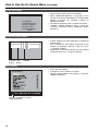
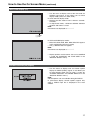
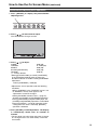
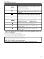
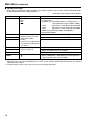
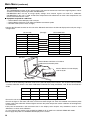
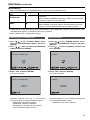
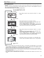
Panasonic Broadcast
BT-LH2550
Menu Information
How to Use the On Screen Menu
The screen displays eight types of information: input signal status, picture/volume adjusting menu status,
sharpness display, FUNCTION display, audio level meter display, menu display, TIME CODE display and CLOSED
CAPTION display.
Input signal status
1. Main window , sub-window
indication
• Indicates whether the main window or sub-window
is displayed.
• In split screen display, the screen synchronized to
the reference sync changes with the input signal
format and “TWO WINDOW SIZE” settings ( page
44).
The screen synchronized to the reference sync is
displayed in white and the screen that is not
synchronized is displayed in yellow.
2. The selected input line ( page 11, 7 )
• VIDEO, SDI1, SDI2,
YPBPR/RGB-VIDEO/RGB-COMP.
DVI-VIDEO/DVI-COMP.
• Use “STATUS DISPLAY” in the “SYSTEM CONFIG”
menu to set the display status ( page 29).
3. Various indications (FILM mode)
• This indicates that “GAMMA SELECT” is set to
“FILM” in the “VIDEO CONFIG” menu.
4. Signal format
• Use “STATUS DISPLAY” in the “SYSTEM CONFIG”
menu to set the display status ( page 29).
• “UNSUPPORT SIGNAL” appears if an unsupported
signal is input. It may also indicate that the format
selected in the “INPUT SELECT” menu does not
match the input signal.
• “NO SIGNAL” appears if no signal is input.
Note:
“UNSUPPORT SIGNAL” and “NO SIGNAL” may not
be properly displayed.
5. Various indications (Lock status)
• This indicates that “CONTROL” is set to “REMOTE”
in the “CONTROL” menu.
Picture/volume adjusting menu
• Press the ADJUST button ( page 11, 9 ) to open
the picture/volume adjusting menu.
• To clear the display, press the ADJUST button again,
press the MENU button or leave it idle for 10
seconds.
• Only adjustments that appear on the screen can be
adjusted.
• The display always appears in the same screen
location.
Sharpness display
• This is the SHARPNESS H/V mode display.
• It disappears after 2 minutes of inaction.
15
How to Use the On Screen Menu (continued)
FUNCTION display
• Use the menu to open and set up functions.
• When “FUNCTION DISPLAY” ( page 32) is set to
ON, press any of the "FUNCTION1" to "FUNCTION5"
buttons to display the functions assigned to
FUNCTION buttons.
• This display disappears after 2 seconds of inaction.
• “XXXXX” indicates operating status ( page 34,
“Functions displayed during FUNCTION button
operation”).
F1:MARKER
F2:WFM/VECTOR
F3:TWO WINDOW
F4:TIME CODE
F5:LEVEL METER
XXXXX
Audio level meter display
1
3
5
7
2
4
6
8
Channel Level
display display
• A white skeleton bar meter indicates the audio level
for SDI signals.
• You can switch the level display on/off and set the
number of displayed channels using the menu
( page 38, “AUDIO”).
• The 0 dB line and channel display can be switched
on/off from the menu ( page 38, “AUDIO”).
0 dB line
Menu display
[MAIN MENU]
Displays instructions on menu
button operations.
16
• This is the menu display.
• It disappears after 2 minutes of inaction.
• You can change position of the display (
“MENU POSITION”).
page 29,
How to Use the On Screen Menu (continued)
TIME CODE display (TC)
• Use the menu to display and set the time code for
HD-SDI signal input. It also allows you to switch
display mode (VITC, LTC, VUB, LUB).
In VITC and LTC display mode:
• Displays the time code in hours: minutes: seconds:
or frames.
• In drop-frame mode, a different delimiter between
seconds and frames is used.
Note:
Read errors are displayed as “--:--:--:--”
( : ) NDF
( . ) DF
In VUB and LUB display modes:
• BG8, BG7, BG6, BG5, BG4, BG3, BG2, BG1 appear
in the stated order. BG: binary group
• The (:) delimiter does not appear.
Note:
Read errors are displayed as “--:--:--:--”
• Display position and character size can be modified
( page 39, “POSITION” and “FONT SIZE” in the
“DISPLAY SETUP” menu).
CLOSED CAPTION (CC) display
• Use the menu to display and set closed caption
display for VIDEO (NTSC) signals. It also allows you
to select display mode (CC1 to CC4) ( page 39,
“CLOSED CAPTION” and “MODE SELECT” in the
“DISPLAY SETUP” menu.).
Note:
Closed captions are not available during HV DELAY.
In split-screen display, closed captions appear only
when a VIDEO input line is displayed in the main
window.
17
How to Use the On Screen Menu (continued)
Menu operations
1. Press [MENU] to display the MAIN menu.
2. Press [ ,
[ENTER].
3. Press [ ,
] to select a sub menu and press
[ENTER].
The settings in the sub menu change to green.
] to select a menu and push
[MAIN MENU]
4. Press [ ,
] to select a setting, then press
[ENTER].
To cancel, press [MENU].
To return to the previous screen
Press the [MENU] button.
18
How to Use the On Screen Menu (continued)
Picture/volume adjusting menu operations
1. Press [ADJUST] to display the picture/volume
adjusting menu.
2. Press [ ,
] to select item to adjust.
The selected item changes to white.
3. Press [ ,
] to adjust.
PHASE
0-60 (30)
CHROMA
0, 10-60 (30)
BRIGHT
0-60 (30)
B.LIGHT [BACKLIGHT]
0-60 (50)
VOLUME
0-60 (0)
( ) : Factory defaults
• Setting [B.LIGHT/CONT.] to CONT. [CONTRAST]
in the [SYSTEM CONFIG] menu changes the
B.LIGHT indication to CONT. enabling CONTRAST
adjustment.
CONT. [CONTRAST] 0-60 (50)
• Adjustments are not possible under the following
conditions.
• When “CONTROL” in the “CONTROL” menu is set
to “REMOTE,” the key mark appears and
adjustments cannot be changed.
• Setting the MONO function to ON ( page 27)
disables the [PHASE] and [CHROMA] operations.
• During [RGB-COMP] and [DVI-COMP] input, the
[PHASE] and [CHROMA] operations are disabled.
• During HV DELAY ( page 33) operation (and a
setting other than OFF is selected), [BRIGHT]
operation is disabled.
4. Press [ADJUST] to end adjustments. The display
is automatically closed after 10 seconds of
inaction.
• The unit loads set values when the power is turned
on. Changed values are automatically saved after
10 seconds.
19
User Data
You can save and load up to five combinations of menu settings and picture/volume adjustments as user data. You
can also return settings and adjustments to their factory defaults.
User data include the following settings.
• Menu settings except “SETUP LOAD/SAVE” and “CONTROL/CONTROL” (including button function settings on
the monitor front panel)
• Screen adjustments made in the picture/volume adjustments menu
Saving user data
Loading user data
1. Press [MENU] to display the MAIN menu.
2. Press [ ,
] to select the “SYSTEM CONFIG”
menu and press [ENTER].
3. Press [ ,
] to select the “SETUP SAVE” sub
menu and press [ENTER].
The setting in the sub menu changes to green.
1. Press [MENU] to display the MAIN menu.
2. Press [ ,
] to select the “SYSTEM CONFIG”
menu and press [ENTER].
3. Press [ ,
] to select the “SETUP LOAD” sub
menu and press [ENTER].
The setting in the sub menu changes to green.
B.LIGHT/CONT.
BACKLIGHT
MENU POSITION
STATUS DISPLAY
SETUP LOAD
SETUP SAVE
POWER ON SETUP
POWER SAVE MODE
CALIBRATION
BACKLIGHT
-CENTER
3SEC OFF
FACTORY
USER1
LAST
OFF
Changes to green
4. Press [ ,
] to select a “USER1” to “USER5”
file to save the settings to and press [ENTER].
The following screen appears.
5. Select “YES” and press [ENTER].
This saves the user data.
To return to the previous screen
Push [MENU].
20
B.LIGHT/CONT.
BACKLIGHT
MENU POSITION
STATUS DISPLAY
SETUP LOAD
SETUP SAVE
POWER ON SETUP
POWER SAVE MODE
CALIBRATION
BACKLIGHT
-CENTER
3SEC OFF
FACTORY
USER1
LAST
OFF
Changes to green
4. Press [ ,
] to select a “USER1” to “USER5”
file to load and press [ENTER].
The following screen appears.
To return to the factory defaults, select “FACTORY.”
5. Select “YES” and press [ENTER].
This loads the user data.
Main Menu
Menu configuration
MAIN MENU
MARKER
MARKER
16:9
VIDEO CONFIG
SYSTEM CONFIG
FUNCTION
GAMMA SELECT
B.LIGHT/CONT.
COLOR SPACE
BACKLIGHT
COLOR TEMP.
MENU POSITION
SHARPNESS MODE
STATUS DISPLAY
SHARPNESS H
SETUP LOAD
SHARPNESS V
SETUP SAVE
I-P MODE
POWER ON SETUP
MONO
COLOR SPACE
ANAMO
POWER SAVE MODE
SD ASPECT
CALIBRATION
SCAN
FUNCTION1
FUNCTION2
FUNCTION3
COLOR GAIN R
COLOR GAIN G
COLOR GAIN B
BACK
EBU
CENTER
ITU-709
GPI PRESET1
WIDE1
GPI PRESET2
WIDE2
MARKER TYPE
WIDE3
CROSS HATCH
USER0-63
D93
D65
D56
VAR1
COLOR TEMP.
VAR2
GAIN RED
VAR3
GAIN GREEN
FUNCTION4
GAIN BLUE
FUNCTION5
BIAS RED
FUNCTION DISPLAY
GPI CONTROL
GPI
INPUT SELECT
4:3
SMPTE-C
GPI1
VIDEO
FORMAT
NTSC SETUP
SDI1
SDI2
YPBPR/RGB
MODE
GPI2
BIAS GREEN
BIAS BLUE
RESET
GPI3
COLOR TEMP.
GPI4
GAIN RED
GPI5
GAIN GREEN
GPI6
GAIN BLUE
GPI7
BIAS RED
GPI8
BIAS GREEN
BIAS BLUE
COMPONENT LEVEL
RESET
SELECT SYNC
AUDIO
COMP.
AUTOSETUP
DVI-D
H POSITION
MODE
V POSITION
INPUT SELECT
EMBEDDED SELECT L
EMBEDDED SELECT R
LEVEL METER
PHASE
CLOCK
WXGA/XGA
RESET
COLOR TEMP.
GAIN RED
GAIN GREEN
GAIN BLUE
BIAS RED
BIAS GREEN
BIAS BLUE
RESET
CH SELECT
0 dB POINT
CH INFO.
DISPLAY SETUP
TWO WINDOW SIZE
SUB INPUT SEL.
WFM/VECTOR
CONTROL
HOURMETER
CONTROL
POSITION
LOCAL ENABLE
VECTOR MODE
OPERATION
LCD
VECTOR SCALE
TIME CODE
POSITION
FONT SIZE
MODE SELECT
CLOSED CAPTION
MODE SELECT
21
Main Menu (continued)
MARKER
This function is not available in split screen display of the TWO WINDOW function. (CROSS HATCH is not
affected.)
Underlined values indicate factory defaults.
Sub menu
MARKER
16:9*2*3*4
Setting
*1
OFF
ON
OFF
4:3
13:9
14:9
CNSCO
VISTA
95%
93%
90%
88%
80%
USER 85%
4:3*2*4
OFF
95%
93%
90%
88%
80%
USER 85%
BACK*2
NORMAL
HALF
BLACK
CENTER*2
OFF
ON
Description
Turns the MARKER setting on and off.
Selects/displays the 16:9 marker type.
<OFF>
No marker display
<4:3>
4:3 marker
<13:9>
13:9 marker
<14:9>
14:9 marker
<CNSCO> CNSCO marker
<VISTA> VISTA marker
<95%>
95% area marker
<90%>
90% area marker
<80%>
80% area marker
<93%>
93.1% area marker (TYPE1)
93% area marker (TYPE2)
<88%>
89.5% area marker (TYPE1)
88% area marker (TYPE2)
<USER> This area marker can be varied in 1% increments in the range
between 80% to 95%. However, an 88% value for a TYPE1
MARKER TYPE indicates an area marker whose height is 89% of
available screen height in the selected aspect ratio.
(The factory default is 85%.)
Selects/displays the 4:3 marker type.
<OFF>
No marker display
<95%>
95% area marker
<93%>
93% area marker
<90%>
90% area marker
<80%>
80% area marker
<88%>
89% area marker (TYPE1)
88% area marker (TYPE2)
<USER> This area marker can be varied in 1% increments in the range
between 80% to 95%. Values of 93% and 88% for TYPE1
MARKER TYPE indicate area markers whose height is 93.1% and
89.5%, respectively, of available screen height in the selected
aspect ratio.
(The factory default is 85%.)
Selects the background brightness around the marker.
<NORMAL> Normal background
<HALF>
50% background brightness
<BLACK>
0% background brightness (black)
Displays/turns off the center marker.
<OFF>
Turns the display off
<ON>
Turns the display on
*1 This setting is turned “ON” when receiving marker control in REMOTE operation. (GPI, if set, has priority.)
*2 These settings are disabled when the GPI function ( page 48) is used to control the marker setting.
They are also disabled in split screen mode.
*3 This setting is enabled only for HD and SD signal input in 16:9 aspect ratio mode.
*4 TYPE1 and TYPE2 area marker size depends on the “MARKER TYPE” setting ( page 23).
22
Main Menu (continued)
Sub menu
GPI
PRESET1*5
GPI PRESET2*5
Setting
4:3
13:9
14:9
CNSCO
VISTA
95% (16:9)
93% (16:9)
90% (16:9)
88% (16:9)
80% (16:9)
USER (16:9)
95% (4:3)
93% (4:3)
90% (4:3)
88% (4:3)
80% (4:3)
USER (4:3)
MARKER TYPE*4*6
TYPE2
TYPE1
CROSS HATCH
OFF
LOW
HIGH
Description
GPI PRESET1: Selects the marker displayed by the GPI terminal
“MARKER1 ON/OFF” ( page 48) operation.
GPI PRESET2: Selects the marker displayed by the GPI terminal
“MARKER2 ON/OFF” ( page 48) operation.
<4:3>
4:3 marker
<13:9>
13:9 marker
<14:9>
14:9 marker
<CNSCO>
CNSCO marker
<VISTA>
VISTA marker
<95% (16:9)> 95% area marker for 16:9 aspect ratio
<93% (16:9)> 93% area marker for 16:9 aspect ratio
<90% (16:9)> 90% area marker for 16:9 aspect ratio
<88% (16:9)> 88% area marker for 16:9 aspect ratio
<80% (16:9)> 80% area marker for 16:9 aspect ratio
<95% (4:3)> 95% area marker for 4:3 aspect ratio
<93% (4:3)> 93% area marker for 4:3 aspect ratio
<90% (4:3)> 90% area marker for 4:3 aspect ratio
<88% (4:3)> 88% area marker for 4:3 aspect ratio
<80% (4:3)> 80% area marker for 4:3 aspect ratio
<USER>
This area marker can be varied in 1% increments in the
range between 80% to 95%.
The above indicates values when the 16:9 and 4:3 sub
menus are selected.
Selects conventional monitor or camera recorder marker size.
Marker size compliant with the camera recorder (Panasonic)
<TYPE2>
<TYPE1>
The marker has the same size as that of the previous
model (BT-LH2600W).
Turns the cross hatch grid on and off and sets its density.
<OFF>
Turns the display off
<LOW>
20/256 gradations (displays a light cross hatch grid)
<HIGH>
70/256 gradations (displays a dense cross hatch grid)
*5 Remote control via RS-232C ends in error (error response: ER001) when “GPI PRESET1” or “GPI PRESET2”
is selected with the GPI function.
*6 Display size for SD signals differ.
TYPE1: The effective horizontal area meets the SMPTE125M for NTSC and ITU-R BT 601-5 for PAL.
TYPE2: The effective horizontal area meets the EIA-RS170 for NTSC and ITU-R BT 470-4 for PAL.
23
Main Menu (continued)
Marker types
■ 16:9 marker
(Displayed for HD input and SD input in 16:9 ratio
mode.)
This marker is only displayed as a vertical bar. The
section becomes the “MARKER BACK”.
4:3 marker
■ 4:3 marker
(Displayed for SD input in 4:3 aspect ratio mode)
This marker is displayed as a dotted line.
95% Area marker
93% Area marker
90% Area marker
88% Area marker
13:9 marker
14:9 marker
VISTA marker, CNSCO marker
This marker is displayed as a horizontal dotted line.
80% Area marker
(Displayed for HD input and SD input in 16:9 ratio mode.)
This marker is displayed as a dotted line.
VISTA marker
CNSCO marker
The marker is displayed as a vertical dotted line
when “UNDER” is selected under “SCAN” in the
“VIDEO CONFIG” menu.
95% Area marker
93% Area marker
TYPE1 Vertical 89%,
horizontal 88%
TYPE2 Vertical/Horizontal 88%
VISTA marker
CNSCO marker
Area marker
This marker is displayed as a dotted line.
90% Area marker
88% Area marker
80% Area marker
TYPE1 Vertical 93.1%,
horizontal 93%
TYPE2 Vertical/Horizontal 93%
95% Area marker
93% Area marker
TYPE1 Vertical 89.5%,
horizontal 88%
TYPE2 Vertical/Horizontal 88%
90% Area marker
88% Area marker
80% Area marker
95% Area marker
USER area marker *1
80% Area marker
*1 Use the
and
buttons to increase or decrease the
area marker in 1% increments in the range between 80
and 95%.
24
95% Area marker
USER area marker *1
80% Area marker
• You can display the 4:3 marker and the 16:9
marker simultaneously.
Simultaneous display example
The
section becomes the “MARKER BACK”. It controls
the background of the marker selected with a 16:9 ratio.
16:9 marker:
95% area marker
4:3 marker
4:3 marker:
16:9 marker
80% area marker
■ Center marker
Center marker
This marker is displayed
at the center of the
screen.
Main Menu (continued)
■ “CROSS HATCH”
The “CROSS HATCH” function enables display of markers at regular vertical and horizontal intervals to facilitate
composition and other tasks. The width of marker lines is 1 dot, the markers consist of 1 line, and are spaced
120 dots apart (fixed value).
Each press of the button (“FUNCTION1” to “FUNCTION5”) to which the “CROSS HATCH” has been assigned
turns the function on and off.
Each press of the FUNCTION button to which the “CROSS HATCH” function is assigned changes the
display as shown.
HD/SD (16:9) mode
1st press
2nd press
Light cross hatch
Dense cross hatch
SD (4:3) mode
3rd press (back to original image without cross hatch)
25
Main Menu (continued)
VIDEO CONFIG
Underlined values indicate factory defaults.
Sub menu
GAMMA
SELECT*1*2
Settings
Description
STANDARD
STDIO/PST
FILM
Selects gamma curve. The gamma curve in the sub-window can be
set in the split-screen display and sub-window display (single screen)
of the “TWO WINDOW” function.
<STANDARD> Standard mode
<STDIO/PST> Color emphasis mode (a mode that approximates CRT
display capability suitable for studio or postproduction
application)
<FILM>
Film mode (For VARICAM use)
The
mark appears at the top left of the screen when “FILM”
is selected.
COLOR SPACE
SMPTE-C*7
EBU*7
ITU-709
WIDE1
WIDE2
WIDE3
Sets the color space. The color space in the sub-window can be set in
the split-screen display and sub-window display (single screen) of the
“TWO WINDOW” function.
<SMPTE-C> SMPTE-C standard
<EBU>
EBU standard
<ITU-709> ITU-R BT. 709 standard
<WIDE1>
Sets the gamma curve to 2.2 in wide color gamut (using
Adobe color space) mode.
<WIDE2>
Sets the gamma curve to 1.8 in wide color gamut (using
Adobe color space) mode.
<WIDE3>
Sets the gamma curve to 2.6 in wide color gamut (using DCinema color space) mode.
COLOR TEMP.
USER0 - 63*5
D93
D65
D56
VAR1
VAR2
VAR3
Selects color temperature. Both the main window and sub-window can
be set up in the split-screen display of the “TWO WINDOW” function.
<USER 0 - 63> Adjustable settings 0 - 63 (equivalent to a color
temperature range of 3,000 - 9,300K)
<D93> Equivalent to a color temperature of 9,300K
<D65> Equivalent to a color temperature of 6,500K
<D56> Equivalent to a color temperature of 5,600K
<VAR1> WB adjustment mode*4
<VAR2> WB adjustment mode*4
*4
<VAR3> WB adjustment mode
USER20 is approximately 5000 K and USER33 is approximately 6300 K.
SHARPNESS
MODE*2
HIGH*3
LOW
Selects the width of outline correction edge. Both the main window
and sub-window can be set up in the split-screen display of the “TWO
WINDOW” function.
<HIGH> Thin edge
<LOW> Wide edge
SHARPNESS H*2
0 - 30*3
Sets horizontal outline correction. The item display moves to the lower
part of the screen during adjustment. Both the main window and subwindow can be set up in the split-screen display of the “TWO
WINDOW” function.
SHARPNESS V*2
0 - 30*3
Sets vertical outline correction. The item display moves to the lower
part of the screen during adjustment. Both the main window and subwindow can be set up in the split-screen display of the “TWO
WINDOW” function.
*1 Changes are not reflected to a still image in the main window in the split-screen display of the “TWO WINDOW”
function.
*2 These functions are not available when “RGB-COMP.” under “YPBPR/RGB” or “DVI-COMP.” under “DVI-D” is
selected in the “INPUT SELECT” menu ( page 36). The gamma curve is set to STANDARD when “RGBCOMP” or “DVI-COMP” is selected. Selecting WIDE1 to 3 for “COLOR SPACE” produces the gamma curve
fixed to that “COLOR SPACE.”
*3 The following sharpness values are available and the settings for the selected input signal is displayed.
Adjustment status during selection appears at the bottom right of the screen.
1) VIDEO system input (VIDEO) (the factory defaults are SHARPNESS MODE: LOW and SHARPNESS H/V: 0)
2) HD for any other input (the factory defaults are SHARPNESS MODE: HIGH and SHARPNESS H/V: 0).
3) SD for any other input (the factory defaults are SHARPNESS MODE: LOW and SHARPNESS H/V: 0).
*4 Selecting “VAR1”, “VAR2” and “VAR3” engages the WB adjustment mode ( page 28).
*5 To select USER0 - 63,
1) Press [ENTER] (“USER” changes to blue).
2) Use [ , ] to select 0 - 63 and press [ENTER].
*7 Factory default setting: SMPTE-C (U.S.A. and Canada), EBU (other countries)
26
Main Menu (continued)
Sub menu
Settings
Description
I-P MODE*2*6
MODE2
MODE1
Selects IP conversion mode. ( page 27, “IP mode”) Both the main
window and sub-window can be set up in the split-screen display of
the “TWO WINDOW” function.
<MODE2> Inter-field interpolation
<MODE1> Inter-frame interpolation
MONO*2
OFF
ON
Switches between color and monochrome (MONO).
<OFF> Color
<ON> Monochrome
• When ON, the CHROMA setting of the picture/volume adjusting menu
is fixed at 0.
ANAMO*2*8
OFF
ON
With an Anamo lens and HD-SDI input, the picture is resized to
Anamo magnification (the vertically enlarged signal can be vertically
compressed and corrected for display). This function is not available in
the split screen display of the “TWO WINDOW” function.
SD ASPECT*2
4:3
16:9
Sets the aspect ratio for SD signal input. This function is not available
in the split screen display of the “TWO WINDOW” function.
<4:3> 4:3 display
<16:9> 16:9 display
SCAN*2
NORMAL
UNDER
Sets under-scan and normal display. This function is not available in
the split screen display of the “TWO WINDOW” function.
<NORMAL> Normal display
<UNDER> Under-scan
COLOR GAIN R
0 - 30
Fine tunes R component GAIN in split-screen mode and sub-window
display (single screen) of the “TWO WINDOW” function.
COLOR GAIN G
0 - 30
Fine tunes G component GAIN in sub-window input in the split-screen
display and sub-window display (single screen) of the “TWO
WINDOW” function.
COLOR GAIN B
0 - 30
Fine tunes B component GAIN in sub-window input in the split-screen
display and sub-window display (single screen) of the “TWO
WINDOW” function.
*2 These functions are not available when “RGB-COMP.” under “YPBPR/RGB” or “DVI-COMP.” under “DVI-D” is
selected in the “INPUT SELECT” menu ( page 36). The gamma curve is set to STANDARD when “RGBCOMP” or “DVI-COMP” is selected. Selecting WIDE1 to 3 for “COLOR SPACE” produces the gamma curve
fixed to that “COLOR SPACE.”
*6 To use the “TWO WINDOW” ( page 34) function,
1) Change settings after exiting the “TWO WINDOW” function.
2) It is recommended to use “MODE2” for handling fast video.
*8 “SCAN” changes are not reflected in Anamo size display.
IP mode
“MODE1” performs IP conversion using inter-frame interpolation.
The factory default is “MODE1”.
“MODE2” performs IP conversion using inter-field interpolation.
Since interpolation is performed inside each field, this mode is suitable for checking interlace status.
27
Main Menu (continued)
■ WB adjustment mode
Select “VAR1” to “VAR3” for “COLOR TEMP.” in the “VIDEO CONFIG” menu to make “WHITE BALANCE VAR1”
to “WHITE BALANCE VAR3” (WB) adjustments.
Underlined values indicate factory defaults.
Sub menu
COLOR
TEMP.*1
GAIN RED
GAIN GREEN
GAIN BLUE
BIAS RED
BIAS GREEN
Settings
Description
USER0 - 6
D93
D65
D56
Selects the color temperature that will become the basis
for adjustment.
<USER 0 - 63> Adjustable settings 0 - 63 (equivalent to a
color temperature range of 3,000 - 9,300K)
<D93>
Equivalent to a color temperature of 9,300K
<D65>
Equivalent to a color temperature of 6,500K
<D56>
Equivalent to a color temperature of 5,600K
USER20 is approximately 5000 K and USER33 is
approximately 6300 K.
0 - 1023
(Factory defaults are color
temperature <D65>
values.)
• These are the adjustments
made before shipment from
the factory.
Adjusts the GAIN elements for RED.*2
-512 - 511
(Factory default: 0)
Adjusts the GAIN elements for GREEN.*2
Adjusts the GAIN elements for BLUE.*2
Adjusts the BIAS elements for RED.*2
Adjusts the BIAS elements for GREEN.*2
BIAS BLUE
Adjusts the BIAS elements for BLUE.*2
RESET
Resets “GAIN RED” - “BIAS BLUE” to color temperature
values selected under “COLOR TEMP.”
*1 Selecting “COLOR TEMP.” and pressing [ENTER] after making a change, opens a confirmation screen.
Selecting “YES” and pressing [ENTER] in this screen resets selected GAIN and BIAS values to the selected
color temperature values.
*2 The item display moves to the lower part of the screen during adjustment.
28
Main Menu (continued)
SYSTEM CONFIG
Underlined values indicate factory defaults.
Sub menu
Settings
Description
B.LIGHT/CONT.
BACKLIGHT
CONTRAST
Selects function to be assigned to BACKLIGHT/CONT. in the picture/
volume adjusting menu.
<BACKLIGHT> Adjusts the BACKLIGHT.
<CONTRAST> Adjusts the CONTRAST.
BACKLIGHT
0 - 50
Adjusts the backlight when the B.LIGHT/CONT. submenu is set to
CONTRAST.
MENU
POSITION
CENTER
LB
RB
RT
LT
Positions the on-screen menu.
<CENTER> Center of the screen
<LB> Left Bottom
<RB> Right Bottom
<RT> Right Top
<LT> Left Top
STATUS
DISPLAY
OFF
3SEC OFF
CONTINUE
Sets display state for input signal status (on-screen menu).
<OFF> Not displayed.
<3SEC OFF> Displayed for 3 seconds after a status change.
<CONTINUE> Displayed at all times
SETUP LOAD
USER5*1*2
USER4*1*2
USER3*1*2
USER2*1*2
USER1*1*2
FACTORY
Loads saved factory defaults (FACTORY) or user data (USER1 - USER5).
After loading user data, the screen displays the signal selected before
user data was loaded.
SETUP SAVE
USER5*2
USER4*2
USER3*2
USER2*2
USER1*2
Up to 5 sets of user data can be saved ( page 20).
They save menu settings and adjustments made in the picture/volume
adjusting menu (PHASE/CHROMA/BRIGHT/CONTRAST/BACKLIGHT)
except “SETUP SAVE/SETUP LOAD.”
POWER ON
SETUP
USER5
USER4
USER3
USER2
USER1
FACTORY
LAST
Selects the settings used when the power is turned on.
<LAST> Starts in the mode used when the power was last turned off.
<FACTORY> Starts up using the factory defaults.
<USER1 - 5> Starts up using USER registered settings.
POWER SAVE
MODE
OFF
ON
Sets the power save mode
<OFF> Does not activate the POWER SAVE mode.
<ON> The backlight dims when no signal (NO SIGNAL) is input for 60
seconds or longer. Signal input or menu operation will return the
backlight to its normal brightness.
CALIBRATION
Connect a CA-210 color analyzer and use this submenu to make a
calibration. It also returns calibration data to factory defaults. ( page 30,
31)
*1 When the monitor is shipped, settings for “USER1” - “USER5” are identical to “FACTORY.”
*2 “H POSITION”, “V POSITION”, “PHASE” and “CLOCK” ( page 37) cannot be saved or loaded.
29
Main Menu (continued)
■ CALIBRATION
The CALIBRATION function in this unit measures LCD panel characteristics from low to high brightness values
and internal monitor processing handles CALIBRATION.
CALIBRATION does not rely on image quality settings since internal signals are used for a calibration.
CALIBRATION in this unit is made at D65 color temperature and calibrations for other color temperatures are
results calculated from this value.
■ Equipment required for calibration
• Konica Minolta CA-210 display color analyzer
• Konica Minolta CA-PU12 or CA-PU15 standard measurement probe
• RS-232C cable (male to male, straight)
• Connect the RS-232C terminal on this unit to the RS-232C terminal on the CA-210 display color analyzer using a
straight cable.
CA-210 side
Pin number
Signal
1
CD
2
RXD
3
TXD
4
DTR
5
GND
6
DSR
7
RTS
8
CTS
9
GND
(Straight)
BT-LH2550 Side
Pin number
Signal
1
N.C.
2
TXD
3
RXD
4
DSR
5
GND
6
DTR
7
CTS
8
RTS
9
N.C.
This unit
Konica Minolta CA-PU12 or CA-PU15
standard measurement probe
Konica Minolta CA-210 display
color analyzer
RS-232C cable
• Be sure to set the following calibration values on the CA-210 display color analyzer. The analyzer will not produce
a correct calibration unless it has been calibrated. For details on setup procedures, refer to the CA-210 User's
Guide.
Calibration
W
R
G
B
x
0.3091
0.6759
0.2029
0.1495
y
0.3429
0.3126
0.691
0.0587
Lv
195.3
47.56
135.2
13.21
• Turn on this unit and perform adequate aging (about 1 hour) before starting calibration.
• Turn off the lights in the room and make sure that no external light can enter the standard measurement probe
before starting the calibration. External light that enters the probe will prevent correct calibration of low brightness
characteristics.
• LCD panel characteristics and instrument error in the display color analyzer may sometimes result in small
differences in values after calibration.
In a fine tuning of the monitor, also set GAIN and BIAS for R, G and B in the COLOR TEMP. VAR mode.
• Do not apply the probe to a WFM/VECTOR display on the screen.
30
Main Menu (continued)
■ CALIBRATION
Select CALIBRATION in the “SYSTEM CONFIG” menu to open the following menus.
Sub menu
Setting
Description
AUTO
CALIBRATION*1
Connect a CA-210 color analyzer and use this submenu to make a
calibration.
Select “AUTO CALIBRATION” and select “YES” in the confirmation
screen that appears to start calibration.
RESET*2
Returns calibration data to their factory defaults.
Select “RESET” and select “YES” in the confirmation screen that
appears to return calibrated values to their factory defaults.
*1 “EXECUTING” is displayed during “AUTO CALIBRATION” and “COMPLETE” appears when calibration ends.
“INCOMPLETE” appears if calibration could not be completed.
*2 When “RESET” ends, “COMPLETE” appears.
Performing AUTO CALIBRATION
RESET operation
1. Press [ , ] in the “SYSTEM CONFIG” menu,
select the [CALIBRATION] submenu and press
[ENTER].
2. Press [ , ], select the [AUTO CALIBRATION]
submenu and press [ENTER].
1. Press [ , ] in the “SYSTEM CONFIG” menu,
select the [CALIBRATION] submenu and press
[ENTER].
2. Press [ , ], select the [RESET] submenu and
press [ENTER].
[AUTO CALIBRATION]
3. Select “YES” and press [ENTER].
This starts calibration.
[AUTO CALIBRATION]
xxxxxxxxx indicates that one of the following
messages with the meaning listed below appears.
EXECUTING: Operation in progress
COMPLETE: Operation completed
INCOMPLETE: Operation did not complete.
(Check RS-232C cable connection.)
[RESET]
3. Select “YES” and press [ENTER].
This starts calibration.
[RESET]
xxxxxxxxx indicates that the following message with
the meaning listed below appears.
COMPLETE: Operation completed
31
Main Menu (continued)
FUNCTION
Underlined values indicate factory defaults.
Sub menu
FUNCTION 1 FUNCTION 5
Settings
HV DELAY
AUTOSETUP
BLUE ONLY
GAMMA SELECT
COLOR SPACE
SD ASPECT
SCAN
TWO WINDOW
SUB INPUT SEL.
WFM/VECTOR
MARKER
LEVEL METER
CROSS HATCH
MONO
TIME CODE
CLOSED
CAPTION
ANAMO
UNDEF
(Factory default:
FUNCTION1:
MARKER
FUNCTION2:
WFM/VECTOR
FUNCTION3:
TWO WINDOW
FUNCTION4:
TIME CODE
FUNCTION5:
LEVEL METER)
FUNCTION
DISPLAY
OFF
ON1
ON2
Description
Selects functions to be assigned to [FUNCTION1] - [FUNCTION5]
(front panel buttons).
<HV DELAY>
Displays synchronizing signals (horizontal, vertical).
The display changes in the following order.
DELAY OFF H DELAY V DELAY HV DELAY DELAY OFF
<AUTOSETUP>
Performs auto setup for PC display.
<BLUE ONLY>
Cuts the red and green signals. Use this function to check phase and
chroma. This button toggles between ON and OFF.
<GAMMA SELECT>*1
Displays the gamma curve.
The display changes in the following order.
GAMMA STANDARD GAMMA FILM GAMMA STDIO/PST
GAMMA STANDARD
<COLOR SPACE>
Sets the color space. The display changes in the following order.
EBU ITU-709 WIDE1 WIDE2 WIDE3 SMPTE-C EBU
<SD ASPECT>
Switches between “16:9” and “4:3.”*1
<SCAN>
Switches between “UNDER SCAN” and “NORMAL SCAN”.*1
<TWO WINDOW>
Sets the split-screen function.*1
The display changes in the following order.
• When the input signal terminals of video displayed in the sub-window
and main window differ
SINGLE MAIN
TWO (L/S, M/M, S/L)
SINGLE SUB
SINGLE
MAIN
• When video from the same input signal terminal is displayed in the
sub-window and main window
SINGLE MAIN
TWO(L/S, M/M, S/L)
STILL
SINGLE SUB
SINGLE MAIN
<SUB INPUT SEL.>
Switches sub-window inputs in split screen mode.
<WFM/VECTOR>
Displays waveform or vector display.
<MARKER>
Turns the marker on and off.
<LEVEL METER>
Turns the LEVEL METER display On and Off.
<TIME CODE>
Turns the time code display on and off.
<MONO>
Switches between color and monochrome.
<CLOSED CAPTION>
Turns the closed caption display on and off.
<ANAMO>
Turns ANAMO On and Off.
<UNDEF>
Undefined
Selects display of functions assigned to [FUNCTION1] [FUNCTION5] (front panel buttons). It also selects button action (1touch, 2-touch, off).
<ON1>
1-touch action to display and perform functions.
<ON2>
2-touch action to display and perform functions.
<OFF>
No function display.
*1 Changes in settings change menu settings.
32
Main Menu (continued)
■ FUNCTION setting restrictions
Settings are not available under the following conditions.
Setting
Conditions that disable operation
HV DELAY
In TWO WINDOW and WFM mode, “INVALID FUNCTION” appears to indicate that
operation is disabled.
When “RGB-COMP.” is selected under “YPBPR/RGB” or “DVI-COMP.” is selected under
“DVI-D” in the “INPUT SELECT” menu, “INVALID FUNCTION” appears to indicate that
operation is disabled.
AUTO SETUP
When something other than “RGB-COMP.” is selected under “YPBPR/RGB” in the “INPUT
SELECT” menu, “NOT RGB-COMP. CH” appears to indicate that operation is disabled.
When “RGB-COMP.” is selected under “YPBPR/RGB” in the “INPUT SELECT” menu and
no signal is input, “INCOMPLETE” appears to indicate that operation is disabled.
GAMMA SELECT
When GPI is set, “INVALID FUNCTION” appears to indicate that operation is disabled.
When “RGB-COMP.” is selected under “YPBPR/RGB” or “DVI-COMP.” is selected under
“DVI-D” in the “INPUT SELECT” menu, “INVALID FUNCTION” appears to indicate that
operation is disabled.
SD ASPECT
When GPI is set, “INVALID FUNCTION” appears to indicate that operation is disabled. In
TWO WINDOW mode and HD signal display, “INVALID FUNCTION” appears to indicate
that operation is disabled.
SCAN
When GPI is set, “INVALID FUNCTION” appears to indicate that operation is disabled.
In TWO WINDOW mode, “INVALID FUNCTION” appears to indicate that operation is
disabled.
TWO WINDOW
When “RGB-COMP.” is selected under “YPBPR/RGB” or “DVI-COMP.” is selected under
“DVI-D” in the “INPUT SELECT” menu, the display toggles between single screen display
of the main window and sub-window. When WINDOW SIZE is something other than M/M,
the SINGLE MAIN and SINGLE SUB screens appear alternately, but no still image screen
appears. When the input signal terminals of video displayed in the main window and subwindow differ, the SINGLE MAIN and SINGLE SUB windows appear alternately, but no still
image screen appears.
WFM/VECTOR
In TWO WINDOW mode, “INVALID FUNCTION” appears to indicate that operation is
disabled.
When “RGB-COMP.” or “RGB-VIDEO” is selected under “YPBPR/RGB”, or “DVI-COMP.” or
“DVI-VIDEO” is selected under “DVI-D” in the “INPUT SELECT” menu, “INVALID
FUNCTION” appears to indicate that WFM operation is disabled. The VECTOR display
does not appear for signals other than SDI input.
MARKER
When “RGB-COMP.” is selected under “YPBPR/RGB” or “DVI-COMP.” is selected under
“DVI-D” in the “INPUT SELECT” menu, “INVALID FUNCTION” appears to indicate that
operation is disabled.
When GPI is set during TWO WINDOW operation, “INVALID FUNCTION" appears to
indicate that operation is disabled.
LEVEL METER
When input is something other than SDI, “INVALID FUNCTION” appears to indicate that
operation is disabled.
MONO
When GPI is set, “INVALID FUNCTION” appears to indicate that operation is disabled.
TIMECODE
When input is something other than HD-SDI input, “INVALID FUNCTION” appears to
indicate that operation is disabled.
ANAMO
When input is something other than HD-SDI signal input, “INVALID FUNCTION” appears
to indicate that operation is disabled.
33
Main Menu (continued)
■ Functions displayed during FUNCTION button operation
Pressing any of the [FUNCTION1] to [FUNCTION5] buttons displays the operations assigned to each button as
shown below.
• HV DELAY
DELAY OFF, H DELAY, V DELAY, HV DELAY
• AUTOSETUP
COMP.AUTOSETUP, COMPLETE, INCOMPLETE,
NOT RGB-COMP.CH
• BLUE ONLY
BLUE ONLY ON, BLUE ONLY OFF
• GAMMA SELECT
GAMMA STANDARD, GAMMA FILM,
GAMMA STDIO/PST
• COLOR SPACE
COLOR SPACE SMPTE-C, COLOR SPACE EBU,
COLOR SPACE ITU-709, COLOR SPACE WIDE1,
COLOR SPACE WIDE2, COLOR SPACE WIDE3
• SD ASPECT
4:3, 16:9
• SCAN
NORMAL SCAN, UNDER SCAN
• TWO WINDOW
SINGLE MAIN, TWO L/S, TWO M/M, TWO S/L,
STILL, SINGLE SUB
• SUB INPUT SEL.
VIDEO, SDI1, SDI2, YPBPR/RGB, DVI-D
• WFM/VECTOR
WFM ON, WFM/VECTOR OFF, VECTOR × 1,
VECTOR × 2, VECTOR × 4, VECTOR × 8
• MARKER
MARKER OFF, 4:3 MARKER, 13:9 MARKER,
14:9 MARKER, VISTA MARKER,
CNSCO MARKER, 95% MARKER, 93% MARKER,
90% MARKER, 88% MARKER, 80% MARKER,
××% MARKER (××% indicates an 80 to 95% USER
setting), MARKER ON
• AUDIO LEVEL METER
METER OFF, METER 2CH, METER 4CH,
METER 8CH
• CROSS HATCH
CROSS HATCH HIGH, CROSS HATCH LOW,
CROSS HATCH OFF
• MONO
MONO ON, MONO OFF
• TIME CODE
LTC, VITC, LUB, VUB, TC OFF
• CLOSED CAPTION
CC1, CC2, CC3, CC4, CC OFF
• ANAMO
ANAMO ON, ANAMO OFF
■ “HV DELAY”
This displays the blanking period. Each press of the button changes the display as follows: “H blanking display”
“V blanking display” “H and V blanking display” “no blanking display.”
34
Main Menu (continued)
GPI
“GPI CONTROL” is used to enable and disable GPI functions and assign functions to each of the GPI terminal pins
( page 48).
Underlined values indicate factory defaults.
Sub menu
Settings
Description
GPI CONTROL
DISABLE
ENABLE
Enables and disables GPI functions
<DISABLE> Disabled
<ENABLE> Enabled
GPI1 - GPI8
UNDEF
MARKER1 ON/OFF
MARKER2 ON/OFF
MARKER BACK
HALF
MARKER BACK
BLACK
CENTER MARKER
INPUT SEL. VIDEO
INPUT SEL. SDI1
INPUT SEL. SDI2
INPUT SEL.
YPBPR/RGB
INPUT SEL. DVI-D
SD ASPECT
SCAN
R-TALLY
G-TALLY
MONO
GAMMA SEL. FILM
GAMMA SEL.
STDIO/PST
SELECT SYNC
Assigns functions to the GPI control terminal pins.
The same items can be set to each terminal ( page
48).
Note:
This function is not available when,
• “SD ASPECT” operation when input signal is HD or PC
• “SCAN” operation when the input signal is PC
• “GAMMA SELECT” operation when the input signal is PC
• “SELECT SYNC” operation when anything other than “RGB-VIDEO” is selected under “YPBPR/RGB” in the
“INPUT SELECT” menu
• “MONO” operation when input signal is PC
35
Main Menu (continued)
INPUT SELECT
Underlined values indicate factory defaults.
Sub menu
Settings
Description
VIDEO
OFF
ON
Turns VIDEO line to the INPUT button on/off. *1
FORMAT
AUTO
NTSC
PAL
Selects the video input format.*2
<AUTO> Automatically selects NTSC or PAL.
<NTSC> NTSC
<PAL> PAL
NTSC SETUP
75
00
Selects NTSC setup level.
<75>
Select this function when using 7.5% setup signals.
(Adjusts the interior of the monitor to the 7.5% setup
level to suit the black level)
<00>
Select this when there is no setup signal.
SDI1
OFF
ON
Turns SDI1 line to the INPUT button on/off. *1
SDI2
OFF
ON
Turns SDI2 line to the INPUT button on/off. *1
YPBPR/RGB
OFF
ON
Turns YPBPR/RGB line to the INPUT button on/off. *1
MODE
YPBPR
RGB-VIDEO
RGB-COMP.
Selects YPBPR (component) or RGB input mode.
<YPBPR>
Selects the YPBPR signal.
<RGB-VIDEO> Selects the video RGB signal.
<RGB-COMP.> Selects the PC RGB signal.
COMPONENT
LEVEL
SMPTE
B75
B00
Selects YPBPR (component) signal input level.
<SMPTE>
Signal level complies with SMPTE and PB and PR are
0.7 Vp-p at 100% chroma.
<B75>
Select this when connecting a Betacam or similar
device with a setup function. (Adjusts the interior of
the monitor to the 7.5% setup level to suit the black
level)
<B00>
Select this when connecting a Betacam or similar
device without a setup function.
SELECT SYNC
INT
EXT
Selects the sync signal when using YPBPR and RGB-VIDEO input.
<INT>
Select when the synchronizing signal is
superimposed on the G or Y signal.
<EXT>
Select to synchronize with an external synchronizing
signal.
COMP.
Performs analog PC settings. (“COMP.”
page 37)
DVI-D
OFF
ON
Turns DVI-D line to the INPUT button on/off. *1
MODE
DVI-VIDEO
DVI-COMP.
Selects DVI-D input mode.
<DVI-VIDEO> Selects the RGB signal input of RGB video.
<DVI-COMP.> Selects PC input.
*1 All five input lines (VIDEO, SDI1, SDI2, YPBPR/RGB, DVI-D) cannot be turned off. An attempt to turn off all
inputs ends when the fourth input line is turned off since it will not be possible to turn off the 5th input line also.
*2 “AUTO” is the factory default, but select a specific format when there is risk that the input signal may be
contaminated by outside noise.
36
Main Menu (continued)
■ COMP.
Set “RGB-COMP” under “YPBPR/RGB” in the “INPUT SELECT” menu and select the “RGB-COMP” input line to
enable the “COMP” menu.
Underlined values indicate factory defaults.
Sub menu
AUTOSETUP
Settings
Description
*1
Automatically adjusts RGB-COMP as well as H POSITION,
V POSITION, PHASE and CLOCK settings of input
formats. Selecting this submenu opens a confirmation
screen and setup starts after choosing "YES" in this
screen.
H POSITION
0 - 30 - 60
Adjusts horizontal image display position.*2
V POSITION
0 - 30 - 60
Adjusts vertical image display position.*2
PHASE
0 - 16 - 60
Adjusts the clock phase in 1/32 clock period increments.*2
CLOCK
700 - 2200
(Factory preset settings:*3)
Adjusts the sampling clock in dot units.*2
WXGA/XGA
XGA
WXGA
Switches between XGA (UXGA) and WXGA (WUXGA).
RESET
Returns “H POSITION”, “V POSITION”, “PHASE” and
“CLOCK” settings in the RGB COMP. input compliant
format to their factory defaults.
*1 Run “AUTOSETUP” when video is displayed across the entire screen area. “EXECUTING” is displayed during
“AUTOSETUP” and “COMPLETE” appears when setup completes.
“INCOMPLETE” is displayed if setup could not be completed.
AUTOSETUP may not provide adequate adjustment for some video input. Use H POSITION, V POSITION,
PHASE and CLOCK to adjust.
*2 Each input format can be adjusted but not when user data is loaded (“SETUP LOAD”
page 29) or saved
(“SETUP SAVE” page 29).
*3 “CLOCK” factory default
FORMAT
CLOCK
FORMAT
CLOCK
640 × 400 (70 Hz)
800
1024 × 768 (70 Hz)
1328
640 × 480 (60 Hz)
800
1024 × 768 (75 Hz)
1312
640 × 480 (75 Hz)
840
1024 × 768 (85 Hz)
1376
640 × 480 (85 Hz)
832
1280 × 768 (50 Hz)
1648
800 × 600 (60 Hz)
1056
1280 × 768 (60 Hz)
1680
800 × 600 (70 Hz)
1040
1280 × 768 (75 Hz)
1712
800 × 600 (75 Hz)
1056
1280 × 1024 (60 Hz)
1688
800 × 600 (85 Hz)
1048
1600 × 1200 (60 Hz)
2160
1024 × 768 (60 Hz)
1344
1920 × 1200 (60 Hz)
2080
37
Main Menu (continued)
AUDIO
Use the following submenus to set headphone output and audio level meters.
Underlined values indicate factory defaults.
Sub menu
Settings
Description
INPUT
SELECT
AUTO
ANALOG
Selects input line for audio output to headphone terminal.
<AUTO>
When an SDI input line is selected with the [INPUT] button on
the front panel:
embedded audio (SDI terminal)
When input lines other than SDI1 or SDI2 are selected with
the [INPUT] button on the front panel:
analog (AUDIO input terminal)
<ANALOG> Analog (AUDIO input terminal)
EMBEDDED
SELECT L
CH1 - CH8
(Factory
default: CH1)
Selects embedded audio channel output to the left (L) speaker.
EMBEDDED
SELECT R
CH1 - CH8
(Factory
default: CH2)
Selects embedded audio channel output to the right (R) speaker.
LEVEL
METER*1
OFF
ON
Selects/turns off the audio level meter displayed by OSD.
CH SELECT
8CH
4CH
2CH
Selects the number of audio level meter channels.
0dB POINT
OFF
ON
Selects and turns off 0 dB line on/off displayed on the audio level meter.
CH INFO.
OFF
ON
Selects and turns off displays on the audio level meter.
*1 When ANALOG is selected in the “INPUT SELECT” menu, the LEVEL METER does not indicate the audio level
meter even when set to ON.
38
Main Menu (continued)
DISPLAY SETUP
Underlined values indicate factory defaults.
Sub menu
TWO
WINDOW
SIZE
Settings
Description
L/S
M/M
S/L
Selects size of split-screen displays.
<L/S> main window LARGE, sub-window SMALL
<M/M> main window MEDIUM, sub-window MEDIUM
<S/L> main window SMALL, sub-window LARGE
SUB INPUT
SEL.
VIDEO
SDI1
SDI2
YPBPR/RGB
DVI-D
Selects sub-window input in split-screen display.
WFM/
VECTOR
OFF
WFM
VECTOR
Switches between “WFM/VECTOR” waveform and vector display.
<WFM>
Displays waveforms.
<VECTOR> Displays vector waveforms.*3
POSITION
LB
RB
RT
LT
Selects the position for the “WFM/VECTOR” waveform display.*3
<LB>
Left Bottom
<RB>
Right Bottom
<RT>
Right Top
<LT>
Left Top
VECTOR
MODE
×8
×4
×2
×1
Enlarges vector waveforms.*3
<× 8>
8×
<× 4>
4×
<× 2>
2×
<× 1>
1×
VECTOR
SCALE
100%
75%
Determines the scale of vector waveform.
<100%>
Displays it at 100% scale.
<75%>
Displays it at 75% scale.
TIME CODE
OFF
ON
Turns the time code display on and off.*1
POSITION
TOP
LEFT
CENTER
RIGHT
Selects position of time code display.
<TOP>
Top center of screen
<LEFT>
Bottom left of screen
<CENTER> Bottom center of screen
<RIGHT> Bottom right of screen
FONT SIZE
LARGE
SMALL
Selects font size of time code display.
<LARGE> Twice the height and width of menu font size
<SMALL> Menu font size
MODE
SELECT
LTC
VITC
LUB
VUB
Selects time code display mode.*1
<LTC>
Displays linear time code (LTC).
<VITC>
Displays vertical interval time code (VITC).
<LUB>
Displays user bits included in LTC.
<VUB>
Displays user bits included in VITC.
CLOSED
CAPTION
OFF
ON
Turns closed caption display on and off.*2
MODE
SELECT
CC4
CC3
CC2
CC1
Selects the closed caption display mode.*2
*1 Available during HD-SDI input signals.
*2 Available during VIDEO (NTSC) input. Closed captions appear as bright lines on line 21 when closed caption is
set to ON and underscan is also on.
*3 Opens the vector display during SDI signal input.
39
Main Menu (continued)
■ “WFM/VECTOR”
The “WFM/VECTOR” function enables display of the waveform and vector display. Use “DISPLAY SETUP” in the
main menu to select “WFM” and “VECTOR” display. ( page 39)
Press the button ([FUNCTION1] to [FUNCTION5] ( page 32)) to which the “WFM/VECTOR” function has been
assigned to turn the function on and off. (This assumes that the “WFM/VECTOR” function has been assigned to
any of the [FUNCTION1] to [FUNCTION5] buttons.)
Press the FUNCTION button to which the WFM/VECTOR function has been assigned.
Normal screen
VECTOR display*1
WFM display
Press the
button again
Press the
button again
WFM (waveform display)
VECTOR
(vector display)
These examples show 16:9 aspect ratio images.
*1 Displayed only for SDI signal input.
40
Main Menu (continued)
■ TWO WINDOW function
The “TWO WINDOW” function displays two inputs selected from VIDEO, SDI1/2, YPBPR/RGB or DVI-D in two
windows.
Each press of the button ([FUNCTION1] to [FUNCTION5]) (page 32) to which the "TWO WINDOW" function has
been assigned changes the display mode.
(In the factory default setting, it is assigned to FUNCTION3.)
Press the FUNCTION button to which
the TWO WINDOW function has been
assigned.
Main window (normal window)
• Main window: Displays input selected by “INPUT” in a single
window.
Video
Press the button
again
Main window Sub-window
Video
Video
Press the button
again
• Main window: Displays input selected by “INPUT.”
• Sub-window: Displays input selected in the “SUB INPUT SEL.”
submenu under the “DISPLAY SETUP” menu.
Change “GAMMA SELECT”, “COLOR SPACE”, “COLOR GAIN
R” “G” “B” submenu settings in the “VIDEO CONFIG” menu to
enable comparison with the main window (video).
Main window Sub-window
Still image
Video
Press the button
again
Sub-window
• Main window: Displays input selected by “INPUT” as a still life
image.
• Sub-window: Displays input selected in the “SUB INPUT SEL.”
submenu under the “DISPLAY SETUP” menu.
Change “GAMMA SELECT”, “COLOR SPACE”, “COLOR GAIN
R” “G” “B” submenu settings in the “VIDEO CONFIG” menu to
enable comparison with the main window (still image).
• Sub-window: Displays input selected in the “SUB INPUT SEL.”
submenu under the “DISPLAY SETUP” menu in a single window.
Video
Press the button
again
Note:
• When the main window and sub-window input setting is “YPBPR/RGB” and “RGB-COMP,” the main window
and sub-window are displayed in a single window. When the input settings for the main window and subwindow are both “DVI-COMP,” they are also displayed in a single window.
• When the input signals selected in the main and sub-window differ, the color shade, etc. may differ slightly.
• When the input signal terminals of video displayed in the main window and sub-window differ, the still image
function does not work.
• The main window is normally displayed on the left side.
• When SDI1 or SDI2 is selected for the main window and sub-window, both windows will show the same
screen.
41
Main Menu (continued)
■ TWO WINDOW size
The “TWO WINDOW SIZE” setting in the “DISPLAY SETUP” menu determines the size of the main window and
sub-window.
• Main window (SD) and sub-window (SD)
1920
1280
640
“TWO WINDOW SIZE” setting: L/S
Display size: 4:3 or 5:4
42
960
“TWO WINDOW SIZE” setting: M/M
• Main window (HD) and sub-window (HD)
1920
1280
640
“TWO WINDOW SIZE” setting: L/S
Display size: 16:9 or 16:10
960
960
960
“TWO WINDOW SIZE” setting: M/M
640
1280
“TWO WINDOW SIZE” setting: S/L
640
1280
“TWO WINDOW SIZE” setting: S/L
Main Menu (continued)
• Main window (HD) and sub-window (SD)
1920
1280
640
960
960
“TWO WINDOW SIZE” setting: L/S
“TWO WINDOW SIZE” setting: M/M
Display size of main window: 16:9 or 16:10
Display size of sub-window: 4:3 or 5:4
• Main window (SD) and sub-window (HD)
1920
1280
640
960
960
“TWO WINDOW SIZE” setting: L/S
“TWO WINDOW SIZE” setting: M/M
Display size of main window: 4:3 or 5:4
Display size of sub-window: 16:9 or 16:10
640
1280
“TWO WINDOW SIZE” setting: S/L
640
1280
“TWO WINDOW SIZE” setting: S/L
• When the main window and sub-window display video from the same input line, TWO WINDOW SIZE is M/M.
43
Main Menu (continued)
■ TWO WINDOW screen sync
In single screen display, the TWO WINDOW screen is synchronized to the frame rate frequency of the input signal
format.
In split screen display, the screen used as a reference for synchronization changes with the input signal format and
“TWO WINDOW SIZE” settings as shown in the following table.
Screen synchronization and display in split-screen mode
TWO
WINDOW
SIZE
Sub-window
Input signal format 1035i
1080i
1080/24PsF
Main window
Input signal format
1080p
720p
NTSC
PAL
480i/p
576i/p
DVI-COMP.
No input
or
incompatible
format
1035i
1080i
1080/24PsF
1080p
720p
L/S
NTSC
PAL
480i/p
576i/p
DVI-COMP.
Main window sync
Split-screen display
No input
or
incompatible format
Main window
sync
Single screen
display
Not displayed.
1035i
1080i
1080/24PsF
1080p
720p
M/M
NTSC
PAL
480i/p
576i/p
DVI-COMP.
No input
or
incompatible format
Main window
sync
Split-screen
display
Sub-window sync
Split-screen display
Sub-window sync
Single screen display
Main window
sync
Single screen
display
Not displayed.
1035i
1080i
1080/24PsF
1080p
720p
S/L
NTSC
PAL
480i/p
576i/p
DVI-COMP.
No input
or
incompatible format
Sub-window sync
Split-screen display
Not displayed.
Sub-window sync
Single screen display
• No screen is displayed when the screen is not synchronized to the reference sync or the reference sync is not
input or is in an incompatible format.
• When the frame frequency of the input signal formats of the main window and sub-window differ, frames may be
skipped in the screen that is not synchronized to the reference sync.
44
Main Menu (continued)
CONTROL
Underlined values indicate factory defaults.
Sub menu
Settings
Description
CONTROL
LOCAL
REMOTE
Selects operation. (with control clock)
<LOCAL>
Enables front panel operation
<REMOTE> Enables remote operation
(front panel operation is locked)*1
LOCAL
ENABLE*2
DISABLE.
INPUT
Selects the disabled operation on the front panel when selecting
“REMOTE” under “CONTROL”.
<DISABLE> Disables all front panel operations.
<INPUT>
Operation using button other than the [INPUT] button is
invalid.
*1 The menu can be displayed when the lock is engaged.
Only “CONTROL/LOCAL ENABLE” menu items are available when the lock is engaged.
The picture/volume adjusting menu does not accept changes when the lock is engaged.
The “LOCAL ENABLE” setting determines operations in lock mode.
The key mark is displayed during lock engagement.
Key mark
[MAIN MENU]
MARKER
*2 Only available when “REMOTE” is selected under “CONTROL.”
HOURMETER
Sub menu
OPERATION
LCD
Settings
Description
*3
Displays the number of hours it has been on.
*3
Displays the number of hours that the backlight has been on.
XXXXXXh
XXXXXXh
*3 “XXXXXX” indicates the number of hours.
“XXXXXX”: 300000 hours or greater is displayed as “OVER”.
45
Main Menu (continued)
■ List of setting restrictions (
Input CH
CH
MARKER
: available, ×: not available)
VIDEO
SDI 1/2
SD
HD
YPBPR
SD
HD
RGB-VIDEO
SD
HD
RGB-COMP.
DVI-VIDEO
SD
HD
DVI-COMP.
MARKER*1
×
×
16:9*1
×
×
4:3*1
×
×
BACK*1
×
×
CENTER*1
×
×
GPI
PRESET1*1
×
×
GPI
PRESET2*1
×
×
×
×
×
×
SHARPNESS MODE*4
×
×
SHARPNESS H*4
×
×
SHARPNESS V*4
×
×
MARKER TYPE*1
CROSS HATCH*2
GAMMA SELECT*3
COLOR SPACE
*3
COLOR TEMP.*4
VIDEO
CONFIG
I-P
MODE*4
×
×
ANAMO*1
×
×
×
×
×
SCAN*1
×
×
×
COLOR GAIN R
*3
×
COLOR GAIN G
*3
×
COLOR GAIN B *3
VIDEO
FORMAT
NTSC SETUP
SDI 1
SDI 2
INPUT
YPBPR/RGB
SELECT *2 MODE
COMPONENT LEVEL
SELECT SYNC
COMP.
DVI-D
MODE
INPUT SELECT
EMBEDED SELECT L
EMBEDED SELECT R
LEVEL METER
AUDIO*2
CH SELECT
0dB POINT
CH INFO.
46
×
×
SD ASPECT*1
*1
*2
*3
*4
×
MONO*4
×
×
×
×
×
×
×
×
×
×
×
×
×
×
×
×
×
×
×
×
×
×
×
×
×
×
×
×
×
×
×
×
×
×
×
×
×
×
×
×
×
×
×
×
×
×
×
×
×
×
×
×
×
×
×
×
×
×
×
×
×
×
×
×
×
×
×
×
×
×
×
×
×
×
×
×
×
×
×
×
×
×
×
×
×
×
×
×
×
×
×
×
×
×
×
×
×
×
×
×
×
×
×
×
×
×
×
×
×
×
×
×
×
×
×
×
×
×
×
×
×
×
×
×
×
×
×
×
×
×
×
×
×
×
×
×
×
×
×
×
×
×
×
×
This function is not available in the split-screen display of the “TWO WINDOW” function.
This function can be set in the split-screen display of the “TWO WINDOW” function.
Settings are reflected to the sub-window in the split-screen display of the “TWO WINDOW” function.
Settings are reflected to the main window and the sub-window in the split-screen display of the “TWO
WINDOW” function.
Main Menu (continued)
Input CH
CH
TWO WINDOW SIZE
SUB INPUT SEL.
WFM/VECTOR
POSITION
VECTOR MODE
DISPLAY
VECTOR SCALE
SETUP*2
TIME CODE
POSITION
FONT SIZE
MODE SELECT
CLOSED CAPTION
CAPTION SELECT
PHASE
CHROMA
Picture
BRIGHT
adjustment*2
CONTRAST
BACKLIGHT
VIDEO
SDI 1/2
SD
HD
YPBPR
SD
HD
RGB-VIDEO
SD
HD
RGB-COMP.
DVI-VIDEO
SD
HD
×
*5
×
×
×
×
×
×
*5
×
×
×
×
×
×
×
×
×
×
×
×
×
×
×
×
*5
×
×
×
×
×
×
×
×
×
×
×
×
×
×
×
×
×
×
×
×
×
×
×
×
×
×
×
×
×
×
×
×
×
×
×
×
×
×
×
×
DVI-COMP.
×
×
×
×
×
×
×
×
×
×
×
×
×
×
×
×
×
×
×
×
×
×
×
×
×
×
×
×
×
×
×
×
×
*2 This function can be set in the split-screen display of the “TWO WINDOW” function.
*5 The VECTOR display appears only during SDI input.
47