1
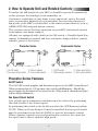
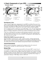
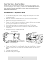
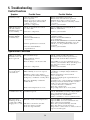
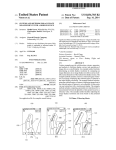
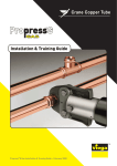
Built Better to Last Longer
User Manual
Central Heat Recovery Ventilation System
For Models
Superventor Series
SHRV40SD
SHRV125SD
SHRV185SD
SHRV240SD
Proventor Series
SHRV120ED
SHRV180ED
Installation Information
________________________
Installing Contractor
_________________________
Telephone Number
________________________
Unit Model Number
_________________________
Unit Serial Number
__________________________
Installation Date
Suggested Operating Instructions
Heating Season
•
Turn HRV ON, fan speed will cycle to LOW. Continuous low speed
ventilation is recommended for fresh air for building occupants.
•
Set adjustable dehumidistat (lower left side of HRV) to off.
•
If home feels too humid or if you have water condensation on windows
Dial built-in dehumidistat (lower left side of HRV) slowly in
CLOCKWISE direction until HRV fan speed changes to HIGH (green
light flashes at high) and allow HRV to run in this position for 24
hours. If symptom continues, repeat previous step until humidity
level is acceptable. Also, if there is a humidifier installed, check to
make sure it is working and its humidistat is set properly (see
humidifier manufacturer’s instructions.)
•
If home feels to dry: Dial dehumidistat (lower left side of HRV) slowly
in COUNTER-CLOCKWISE in 5 point increments and allow HRV to
run in this position for 24 hours. If symptom continues, repeat this
step. Also, if there is a humidifier installed, check to make sure it is
working properly.
•
If higher rate of continuous ventilation is desired: Press SELECT
button (upper right front of HRV) once to change to the next run speed.
•
If HRV continuous ventilation is not desired (only recommended
if windows are left open:) Press SELECT button (upper right front of
HRV) until LED at AUTO/OFF is illuminated. HRV will not run
unless remote bush button is pressed or built-in dehumidistat senses
humidity above setting. Push button activation results in 20 minutes
of high-speed ventilation. After 20 minutes, HRV will return to
AUTO/OFF. Dehumidistat activation results in high-speed ventilation
until humidity level of indoor air is less than the dehumidistat setting,
then HRV will return to AUTO/OFF. If house is too dry, it’s best to
install a humidifier rather than shutting off HRV.
Air Conditioning Season
•
Continuous ventilation is recommended when house is being heated
or cooled: For summertime operation of HRV, turn dehumidistat
setting counter clockwise to off (80%), set run speed to LOW.
Changing the stale indoor air with fresh outdoor air is just as
important in the cooling season as it is in the heating season!
•
If no HRV ventilation is desired (only recommended if windows are
left open): Press SELECT button (upper right top of HRV) until LED
at AUTO/OFF is illuminated. HRV will not run unless remote push
button is pressed. Push button activation results in 20 minutes of
high-speed ventilation. After 20 minutes, HRV will return to AUTO/OFF.
Continuous low speed HRV ventilation is recommended throughout
the year.
Remote Control Devices
•
Summeraire Digital Air Monitor wall control: When using wall
control, set HRV built-in dehumidistat (lower left side of HRV) to off.
Operate HRV as outlined above, but from wall control. Air Monitor
dehumidistat setting at “85%” is OFF.
•
Summeraire 20 minute lighted push button switch: Push button
switches HRV to high speed for 20 minutes. Button lights while HRV
is running at high speed.
•
Summeraire remote wall dehumidistat: When using remote wall
dehumidistat, set HRV built-in dehumidistat (lower left side of HRV)
to OFF. Adjust humidity level from wall dehumidistat.
Table of Contents
1. Description of Your Unit and its Benefits . . . . . . . . . . . . . . . . . . . . . . . . . . .3
2. How to Operate Unit and Related Controls . . . . . . . . . . . . . . . . . . . . . . . . . . .4
3. Basic Components of your HRV . . . . . . . . . . . . . . . . . . . . . . . . . . . . . . . . .11
4. Maintenance. . . . . . . . . . . . . . . . . . . . . . . . . . . . . . . . . . . . . . . . . . . . . . .12
5. Troubleshooting. . . . . . . . . . . . . . . . . . . . . . . . . . . . . . . . . . . . . . . . . . . . . 16
6. Warranty . . . . . . . . . . . . . . . . . . . . . . . . . . . . . . . . . . . . . . . . . . . . . . . . . 17
Introduction
This Manual provides you with an introduction to the principles of Heat Recovery
Ventilators (HRV), the operation and maintenance of your unit, guidelines to
troubleshoot minor problems as they may occur and an outline of your warranty.
Each of these areas are described fully under their specific headings as set out in
the Table Of Contents.
To obtain information relating to the installation, technical specifications and
exploded part diagrams for your unit, please refer to the Installation Manual.
We congratulate you on your purchase of this unit and thank-you for choosing
SUMMERAIRE to provide your fresh air comfort to your family.
2
1. Description of Your Unit and its Benefits
Since the energy crisis in the early 1970’s, governments and the building
community have sponsored many programs and changed codes to foster
reduced energy requirements and create energy costs savings for the
consumer. Each of these efforts, while improving the energy efficiency of
our homes and buildings, has resulted in the loss of natural ventilation and
trapped excess humidity and pollutants indoors.
It is due to this air tightness that your dwelling or place of business
will incur humidity from everyday activities such as cooking, bathing,
washing, indoor drying of clothes and normal breathing and perspiration.
Pollutants such as smoke from cooking and fireplaces or wood burning
stoves, dust, pollens, airborne viruses and molds and radon gas can also be
trapped in your residence.
Your SUMMERAIRE Heat Recovery Ventilator (HRV) is designed to
resolve these problems by providing fresh air into your home or building
while exhausting an equal amount of stale, humid air. This “exchange”
process enables you to remove undesirable pollutants continuously as
well as excess humidity during the heating season. The advantage offered
by your HRV is that it transfers the energy from your exhausted (inside
conditioned air) to temper the incoming fresh air stream.
Fresh Air
Supply
Exhaust Air
To Outside
Tempered
Air Supply
Indoor Air
Exhaust
3
2. How to Operate Unit and Related Controls
To realize the full benefit of your HRV, it should be operated continuously
as this prevents the buildup of stale unhealthy air.
Continuous ventilation of your home is very important, and as the need
arises to introduce higher levels of ventilation, you can select increased
fan speeds at the HRV, or if installed, at the remote control devices such as
AIRMONITORS and push button stations.
This section reviews the basic operation of your HRV and related controls
to maximize your home comfort.
All units are equipped with a built in On/Off switch, a Variable Speed Fan
control, Dehumidistat control and have automatic damper defrost control,
which is preset at the factory.
Proventor Series
Superventor Series
1
1
3
2
2
3
4
4
1. On/Off switch
3. Defrost indicator
2. Fan speed select switch 4. Internal dehumidistat
1. On/Off switch
3. Option select button
2. Status display indicators 4. Internal dehumidistat
Proventor Series Features
On/Off Switch
The ON/OFF switch supplies and disconnects power to the HRV control board.
When positioned in the ON position, this switch will illuminate. Should the
power supply be disconnected or turned to the OFF position, the indicator light
will no longer illuminate.
Fan Speed Select Switch
Low or high speed continuous ventilation may be selected by positioning
this slide switch at the desired speed.
By positioning this switch to the far left you select the OFF/Remote position.
NOTE: When an Econo Remote Control is installed, the fan speed switch
must be positioned to the far left (REM) to activate the remote control.
When a remote control is not used position this switch to the center for
low speed and to the far right for high speed.
4
Internal Dehumidistat
This control regulates the desired amount of humidity in your home. By
simply adjusting the rotary knob on the left hand side of the HRV varied
levels of relative humidity can be selected.
During the colder months of winter, the Internal Dehumidistat should be set
to an industry recommended comfort range of 30% to 40% relative humidity
(R.H.). If the house feels too dry, then adjust the setting higher and if too damp,
then adjust the setting lower.
During the colder months, the Internal Dehumidistat should be should
be set lower if moisture develops on the windows. In the warmer months,
when the outdoor humidity is equal to or greater than the indoor humidity,
the dehumidistat should be turned to the OFF position.
Superventor Series Features
On/Off Switch
The ON/OFF switch supplies and disconnects power to the HRV control
board. When positioned in the ON position, this switch will illuminate.
The switch will not illuminate if the power supply is disconnected or the
switch is turned to the OFF position.
Status Display Indicators
The LED indicator lights illuminate to indicate the current active mode of
operation. The defrost indicator will illuminate when the HRV cycles into
the automatic defrost cycle. This occurs automatically at a predetermined
cycle time whenever the outside air stream entering the HRV is colder then
26 degrees Fahrenheit (-3 degrees Celsius).
Option Select Button
By depressing the SELECT button momentarily, you can select low, medium/high
& high ventilation fan speeds, as well as the AUTO/ OFF mode. The fan speed or
option selected will be indicated by the respective LED on the HRV display panel.
Internal Dehumidistat
This control regulates the desired amount of humidity in your home. By
simply adjusting the rotary knob on the left hand side of the HRV varied
levels of relative humidity can be selected.
During the colder months of winter, the Internal Dehumidistat should be set to
a comfort range of 30% to 40% relative humidity (R.H.). If the house is too dry,
then adjust the setting higher and if too damp, then adjust the setting lower.
During the colder months, the Internal Dehumidistat should be should
5
be set lower if moisture develops on the windows. In the warmer months,
when the outdoor humidity is equal to or greater than the indoor humidity,
the dehumidistat should be turned to the OFF position.
The HRV front panel LED’s will all illuminate and then systematically,
from top to bottom turn off until only the low speed LED is left on.
This is a self-test feature. Note that the HRV will default to low speed
after the test cycle is completed.
Defrost Cycle (Superventor & Proventor Series)
All models are equipped with electronically controlled damper defrost.
When the outdoor temperature entering the HRV drops below 26 F
(-3 C) the defrost timer is activated. After approximately 25 minutes
of normal operation (during which time the core unit may experience
some frost build-up during the heat recovery process) the timer
activates the damper door mechanism which closes off the fresh air
supply port and opens the defrost port. After approximately 4 ½
minutes of defrosting the recovery core, the damper door reverses
direction and reopens the fresh air port and closes off the defrost port
(top of HRV) and the unit returns to normal operation. The cycle
will repeat itself until the outdoor temperature entering the HRV rises
above 26 F (-3 C).
Auto/Off
When this mode of operation is selected, the HRV ventilator fan will be
turned off until activated by the internal dehumidistat or an optional
external control such as a Wall Mount Dehumidistat, Push Button
or remote Airmonitor. This selection is displayed by the continuous
illumination of the Auto/Off LED on the HRV. When conditions
require the fan be activated, this will be indicated by the flashing On
and Off of the High-speed indicator on the HRV control panel.
High Speed Flashing
When the internal dehumidistat or an external control has activated the
HRV to high speed, the High Speed LED light will illuminate and flash.
If you have already selected one of the ventilation speeds as discussed
in the previous section “Select Push Button”, and the High Speed has
been activated, then you will see both the continuously lit LED light
for the fan speed selection and the high speed LED flashing. Once the
device initiating the high speed cycle has been satisfied, the ventilation
fan will reset to the pre-selected mode and the flashing High Speed LED
will turn off.
6
Optional Controls
Remote Push Button
Push buttons are typically installed in any room
where 20 minutes of high-speed ventilation may
be desired, i.e. bathrooms and/or kitchens. Once
activated by a momentary push these buttons
illuminate to indicate high speed activation. If more
than one button is installed in the system then all
the buttons will illuminate upon activation until the
timed sequence has expired. To cancel a Push Button
selection the power to the HRV must be turned off.
Wall Mount Dehumidistat
This control is typically installed in an
area of the home where humidity may
require automatic monitoring thereby
permitting localized control of indoor
relative humidity. This could be a central
location (i.e. near furnace thermostat) or
in a specific room (i.e. kitchen, laundry etc.)
Econo Remote Control
Designed specifically for the PROVENTOR
series of residential HRV’s. This control
is typically installed in a central location
thereby permitting remote operation of the
HRV. Control options include remote R.H.
sensing and level control, (automatic highspeed activation occurs when R.H. exceeds
pre-selected level), fan speed selection and
the ability to turn the HRV off. To activate
this control the fan speed select switch on
the HRV must be set to remote.
7
Airmonitor Control
Designed specifically for the SUPERVENTOR “SD”
series of residential HRV’s. This control
is typically installed in a central location
thereby permitting remote operation of the
HRV. Control operations include remote R.H.
sensing and level control, (automatic highspeed activation occurs when R.H. exceeds
pre-selected level), fan speed selection,
intermittent ventilation (20 minutes ON/40
minutes OFF), Auto OFF (ventilation only
occurs as requested by push button, timer
and/or remote dehumidistat) 20 minutes high
speed and the ability to turn the HRV off.
This control has a liquid crystal display of the
HRV’s status and R.H. set point and values.
AIRMONITOR is designed to provide you with convenient remote control
of your SUMMERAIRE heat Recovery Ventilator.
Operating Instructions
INITIAL START-UP
When the H.R.V. is initially turned on after the AIRMONITOR has been
installed, “WELCOME TO SUMMERAIRE HRV” appears on the L.C.D.
screen and remains for approximately 2 1/2 minutes during which time
the AIRMONITOR and the H.R.V. conduct a complete self diagnostic
check of the system of both devices. When the diagnostic check is
complete (approx. 90 seconds) the L.C.D. screen “defaults” to “STATUS :
LOW”. This indicates that the H.R.V. is now operating on “LOW Speed”
which is normal Constant Run Speed used in all H.R.V. installations.
MODE SELECT
To change the Constant Run Speed, push “MODE SELECT / RH
INCREASE” button. The L.C.D. screen will display “MEDIUM - MEDHI - & HIGH” (speed selection changes each time this button is depressed
until “HIGH” is indicated on the L.C.D. screen).
The next activation of this button “INTRMT” appears on the L.C.D. screen
indicating that the AIRMONITOR has been directed to operate the H.R.V.
in “INTERMITTENT” Mode. (see description of this mode next page).
The next activation of this same button the L.C.D. screen will display
8
“AUTO/OFF”. The AUTO/OFF mode is described next page.
A further activation of this button, the L.C.D. screen will display “OFF”.
When this mode is displayed, the H.R.V. will not respond to any control
device.. The H.R.V. can be returned to regular operation Mode by
activating the “SET RH” button - once.
R H SETTINGS (Relative Humidity)
To select the desired “RH” (relative humidity) value, activate “RH” button,
the L.C.D. screen displays “HUMID: 85% (default setting) -----SAVE
ADJ. -/+”. Depress “RH DECREASE/MODE SELECT” button until
desired setting/value is reached. Push “SET RH” button and “SAVE” this
setting. The Humidity setting will remain at this setting until you reset
the RH value/setting, or, if the power to the H.R.V. is shut off or a power
interruption occurs, in which case the “RH” setting will default to 85%.
Definitions - Settings Available On Summeraire Airmonitor
SPEED SELECT
As described in the “MODE SELECT” portion of these instructions, 4
speeds are available for the “Constant Run” operation. However, you
should select the “LOW SPEED” setting for “CONSTANT RUN”. This
insures that your house will constantly exhaust stale air and receive an
equal amount of outdoor fresh air. When your SUMMERAIRE H.R.V.
is activated by one of the control devices, i.e. the DEHUMIDISTAT,
AIRMONITOR 20 MIN. TIMER (or the optional 20 Min. Push button
Kit), etc, the H.R.V. ventilates at “HIGH” speed. When any of these
Control Devices has been satisfied i.e. the Humidity has been lowered
to your present RH value or the timer has expired on the 20 MIN.
TIMER(s), the H.R.V. will return to your Constant Run speed.
INTERMITTENT
The “INTERMITTENT” Mode automatically ventilates at “LOW SPEED”
(or preselected Constant Run speed) once every hour for 20 minutes, and
remains idle for 40 minutes. However, if the humidity level exceeds the
selected value, the H.R.V. will operate on HIGH SPEED until the level
has been reduced below the selected value. Also if the 20 MIN. SELECT
button on the AIRMONITOR, or, if a button on the Optional 20 MINUTE
TIMER has been operated, the H.R.V. will operate on HIGH SPEED for
the 20 minute time period. In both instances, when the Control Device
has been satisfied, the H.R.V. will return to the “IDLE” portion of the
INTERMITTENT Mode.
9
AUTO / OFF
Some H.R.V. applications may create an internal atmosphere that
is too dry. If this is the case in your home, you should operate your
SUMMERAIRE H.R.V. on AUTO / OFF Mode. When a Control Device
is activated, your H.R.V. will operate at HIGH SPEED. When the Control
Device is satisfied, the H.R.V. will SHUT OFF (does not operate on
Constant Run Speed).
20 MIN. SELECT
Push the 20 MIN. SELECT button on the AIRMONITOR if you require
temporary HIGH SPEED Ventilation… H.R.V. will Ventilate on HIGH
SPEED for 20 minutes, and then return to your preselected Constant Run
Speed. NOTE: 20 Minute HIGH SPEED Ventilation may also be activated
if your H.R.V. system is equipped with the Optional 20 MINUTE PUSH
BUTTON TIMER KIT.
RELATIVE HUMIDITY - RH SETTINGS
This mode controls the excess Humidity in your home. Refer to your
Owner’s Manual / Operating Instructions; it identifies the correct “RH”
SETTINGS.
NOTE: If the Internal Dehumidistat Mode in the AIRMONITOR are
activated…the H.R.V. responds to HIGH SPEED. When the Dehumidistat
settings are satisfied, or, if the “RH” SETTING is increased, (permitting
more humidity to be present in your Home), the return of the H.R.V. to
your preselected Constant Run Speed is delayed for 60 seconds.
Remote Control Functions
10
3. Basic Components of your HRV
Proventor Series
Superventor Series
8
1
1
7
9
2
5
2
3
6
4
3
6
1.
2.
3.
7.
Figure 8
4
On/Off switch
Fan speed select switch
Internal dehumidistat
Damper Door
7
4. Heat Recovery Core
5. Air Filters
6. Condensate Tray
1.
2.
3.
4.
Heat Recovery Core
Figure 9
5
On/Off switch
Status display panel
Select button
Internal dehumidistat
5.
6.
7.
8.
9.
Hear Recovery Core
Air Filters
Condensate Tray
Door Safety Switch
Damper Door
One of the most important components of your HRV is it’s Heat Recovery Core.
In the winter months, during the heating season, this plated Core recovers energy
from the stale humid air being exhausted and transfers this energy to temper the
incoming colder fresh air. This process also reduces indoor relative humidity.
In the summer months, during the air conditioning season, the incoming fresh
air is conditioned as it passes through the Core. This occurs as the conditioned
indoor air being exhausted cools the Core and the incoming fresh air stream.
The Core is designed of an impenetrable polymer material so that the air
streams remain separate (no cross-contamination) thereby ensuring that
the fresh air is not exposed to the potential contaminants and humidity in
the exhausted air stream.
Safety Door Switch (Superventor models only)
Inside the HRV control panel is a safety switch (see fig 9). When replacing the
HRV access door, please ensure that the flange on the inside of this door fits into
the slot on the control cover panel. Failure to successfully insert the flange into the
slot will result in a No Power Condition and potential harm to the mechanism.
Internal Dehumidistat
Indoor relative humidity is monitored continuously by the internal
dehumidistat during all ventilation modes of operation.
Damper Door
This damper door is operated automatically by the main HRV control, based
on outdoor air temperatures. When activated this damper closes off the defrost
air intake port at the top of the HRV. During the defrost cycle (approx 4.5 mins
during a 30 min cycle) the damper door is automatically positioned to close off
the outside fresh air supply port. Do not attempt to reposition this damper as
permanent damage to the damper motor will result.
11
4. Maintenance
In addition to the maintenance procedure outlined below, we recommend
that you inspect the exterior hoods on your unit every month. This is
to ensure that your exhaust and fresh air supply ports are not restricted
by debris (i.e. cottonwood, leaves, grass, snow or frost (ice) buildup on
the mesh cover(s). Restriction of these ports will cause the unit to work
inefficiently and malfunction.
We caution you to unplug the unit prior to performing maintenance or
working inside the unit. Please do not attempt to reposition the damper door
as this will cause permanent damage to the motor.
Every Six Months
Disconnect the power supply
1.
Unlatch the door latches at top of door panel (you will have to remove
latch screws first on the Proventor models only) and gently lower the
door to a level position while securely holding the door panel in place
(apply pressure to the RT.) (Caution - Door can slip off hinges.) Once
open, hold the access door securely and slide it to the left. This will
disengage the lower hinges allowing the door to be removed.
12
2.
Remove the filters as shown and wash in warm, soapy water, rinse, let
dry and replace.
3.
Clean the HRV Core by sliding it out evenly along the channel tracks, then
wash in warm soapy water, rinse, let dry and replace. To replace properly, slide
the core back into the tracks with the label attached to the core indicating the
top upright position of the Core, in the most top upright location.
We suggest that you wear gloves when handling the Core as some
edges may be sharp.
Positioning
Label
NOTE: A power sprayer on a low setting may also be used to clean both
the filter and the core.
4.
Clean and inspect the condensate trays and drain hose. Observe the tray
outlets and the drain hose to ensure they are clear of debris. If debris is present
flush out the drain system with warm soapy water or have the hose replaced.
Clean the condensate trays by wiping with a damp cloth.
13
Every Three Years – Clean Fan Blades
Fan blades can accumulate dusts and dirt creating reduced airflow and
potential imbalance of the blades. It is also our recommendation that
you consider having a qualified service contractor perform your
Fan Blade maintenance.
Fan Maintenance – Superventor Series
1.
As described in the prior section, unplug unit and open access door
(swings forward).
2.
Slide the air filters and Heat Recovery Core forward and remove.
3.
Remove the electrical control box cover.
4.
Using a #2 (red) Robertson screwdriver, remove the fan tray securing
the screw at the inside rear of the fan tray.
5.
Loosen the front fan tray securing screw by one (1) full turn.
6.
Disconnect the wire leads at the connector on the left side of the
control box.
7.
Swing the fan tray assembly forward.
Wire Lead Connector
Wheel Blades
Front Fan Tray
Securing Screw
Fan Tray Securing Screw
8.
Using a small brush (i.e. toothbrush), clean the wheel blades. Caution
must be exercised not to disturb the balancing weights on the wheel
blades.
9.
Vacuum and reassemble.
10. Reconnect the power supply.
14
Fan Maintenance – Proventor Series
1.
As described in section 4.1 unplug HRV and remove front access door.
2.
Slide the air filters and Core forward and remove.
3.
Unplug the motor leads at the connector located beneath the fan tray.
4.
Remove the fan tray securing screws as shown in the drawing below.
5.
Slide the fan tray to the left. It is recommended that you wear gloves
when handling the fan assembly as it may have some sharp edges.
6.
Using a small brush (i.e. toothbrush), clean the wheels. Caution must
be exercised not to disturb the balancing weights on the blades.
7.
Vacuum and reassemble.
8.
Reconnect power supply.
Wheel Blades
Damper
Door
Fan Tray Securing Screws
15
5. Troubleshooting
Control Functions
Symptom
Possible Cause
Possible Solution
Nothing works
Unit not plugged in.
Lack of power.
Front access door safety switch
flange improperly inserted into
control cover slot.
Defective component.
Ensure that HRV is plugged in.
Ensure that outlet in use is powered
Unlatch door, inspect safety switch
probe to ensure that it is entering control
cover slot.
Contact your installer
HRV front panel
On/Off switch
illuminates but fan
is not running
Mode of operation selected set
to “Auto Off”
Select a different operating mode at
HRV or Airmonitor
Defective component.
Contact your installer
HRV status panel
flashing HIGH
Continuously
HRV internal dehumidistat
set too low.
External dehumidistat
set too low.
Adjust dehumidistat RH setting to
a higher setting.
Adjust external dehumidistat
set point higher .
If an external dehumidistat is used then the HRV
internal dehumidistat should be set to off.
Check to see if a push button has been
activated.
Contact your installer.
Remote push button activated.
Defective dehumidistat
or push button.
Operational Functions
HRV is operating
but little or no air
flow is present.
Air stream blockage
Dirty air filters or heat
exchanger Core.
Heat exchange core frozen solid.
Defective component.
Poor air quality,
excess moisture
on windows.
HRV turned off.
HRV running on too low a speed.
If HRV is connected to furnace
ductwork (both exhaust and supply.)
Temporary conditions causing effect.
Excessive humidity conditions
within home.
Indoor air temperature too low.
Indoor air
considered too dry
HRV set at too high a
ventilation speed.
Check outside weather hoods for
blockages such as snow, grass, insects.
Inspect and clean air filters and Core.
Open HRV access door and defrost Core.
Contact your installer. Have unit inspected
for- defective sensors, check system
balancing.
Contact your installer.
Adjust ventilation rate higher and monitor
conditions overnight. Adjust further if
necessary.
Ensure that furnace fan is turned
on to circulate air.
Activate to high speed at push buttons or
Airmonitor.
Consider source such as improper foundation
drainage, moisture intrusion into exterior
walls, excessive moisture generation,
excessive moisture conditions.
New wet construction.
Keep temperature above 18 C (64 F)
Set to a lower speed.
Check dehumidistat settings. Adjust higher.
Set to intermittent mode of operation.
Temporarily use a humidifier.
Add a 7/24 timer to lower ventilation rate.
Excessive frost
Extreme outdoor air temperatures.
build up on ducts
connected to HRV.
Supply air too cold. Imbalance in air flow streams.
Defective defrost system.
Defective Vapor Barrier.
16
Operate HRV on intermittent.
Operate HRV at a lower ventilation rate.
Have a duct heater installed.
Have the system’s balancing checked.
Have the defrost system checked.
Inspect duct connections at collars, look for
vapor tear and repair.
6. Warranty
HRV Unit
Trent Metals Limited warrants the entire Heat Recovery Ventilator to the
original purchaser should it prove to be defective by reason of defective
material and or faulty workmanship with in two (2) years of the purchase
date. Extended warranties are offered for the “Core” and “Electrical
Components” as outlined below.
Core
Trent Metals Limited warrants the “Core” of the Heat Recovery Ventilator
to the original purchaser if the core has become defective by reason of
defective material and/or faulty workmanship, subject to the following:
a) Superventor Series Core- warranty applies to the original
purchaser of the Heat Recovery Ventilator for as long as they own
the dwelling.
b) Proventor Series Core – warranty applies to the original purchaser
of the Heat Recovery Ventilator for a period of fifteen
(15) years from the date of purchase as long as they own the dwelling.
Electrical Components
Trent Metals Limited warrants the “Electrical Components” of the Heat
Recovery Ventilator to the original purchaser if any of the electrical
components have become defective by reason of defective material and/or
faulty workmanship, subject to the following:
a) Superventor Series Electrical Components- warranty applies to the
original purchaser of the Heat Recovery Ventilator for a period of
five (5) years from the date of purchase as long as they own the
dwelling.
b) Proventor Series Electrical Components – warranty applies to the
original purchaser for a period of two (2) years from the date of
purchase as long as they own the dwelling.
17
General Provisions
Trent Metals Limited will supply a replacement HRV unit or component as
prescribed in the foregoing section, F.O.B. Peterborough, Ontario, Canada.
Replacement units and/or components are warranted for the remainder of
the original warranty period.
This warranty does not cover defects caused by: modifications, alteration,
abuse to, or misuse of the product or it’s operation in a manner contrary to
the instructions included with the unit at the time of shipment, or failure
to perform maintenance as detailed in aforementioned instructions.
This warranty expressly supersedes all other warranties and obligations of
Trent Metals Limited. No person has authority to alter or modify the terms
of this warranty in any manner.
This warranty does not include any freight, labour, including diagnostic
labour, or sales tax that might be incurred by the purchaser if a unit and/or
parts require replacement.
Under no circumstances shall Trent Metals Limited be liable to the purchaser
or any other person(s) for any consequential damages, whether arising out of
breach of warranty, breach of contract, negligence or otherwise.
Keep your warranty at work for you. Please complete and mail your
Warranty Registration Card to Trent Metals Limited, 2040 Fisher
Drive, Peterborough, Ontario, Canada, K9J 6X6 to register this warranty.
Summeraire Mfg.
2040 Fisher Drive,
Peterborough, Ontario, Canada
K9J 6X6
X-USRMAN SD 8.6.04