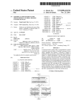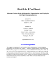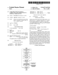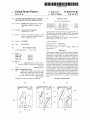
1
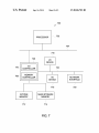
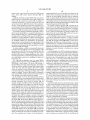
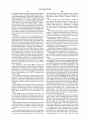
US008836703B2
(12) United States Patent
(10) Patent N0.:
(45) Date of Patent:
Venon et al.
(54)
(56)
SYSTEMS AND METHODS FOR ACCURATE
US 8,836,703 B2
Sep. 16, 2014
References Cited
MEASUREMENT WITH A MOBILE DEVICE
U.S. PATENT DOCUMENTS
(75) Inventors: Medhi Venon, White?sh Bay, WI (US);
2006/0104545 A1 *
5/2006
Christopher Janicki, Barrington, IL
2008/0036693 A1 *
2/2008 Driver et al.
(Us)
2011/0122139 A1*
2012/0127131 A1*
5/2011
5/2012
Schenectady, NY (US)
Appolicious iPhone and iPad App Directory “Calgary Scienti?c: Res
MD Application for Smarphone and Tablet PC” http://wwwappoli
cious.c0m/hea1th/apps/l74234-res01utionmd-m0bile-calgary-scien
Subject to any disclaimer, the term of this
patent is extended or adjusted under 35
ti?c (Last Accessed on Aug. 23, 2012).
“OsiriX HD User Manual” http://WWW.0sirix-viewer.c0m/iph0ne/
U.S.C. 154(b) by 421 days.
Manual .pdf (Last Accessed Aug. 23, 2012).
(21) App1.No.: 13/236,948
* cited by examiner
(22) Filed:
Assistant Examiner * Nurun N Flora
Primary Examiner * Kee M Tung
Sep. 20, 2011
(74) Attorney, Agent,
(65)
Prior Publication Data
US 2013/0069946 A1
(51)
Mar. 21, 2013
and methods to facilitate display, revieW, and annotation of
image data on a small display. An example method includes
determining an initial display resolution by comparing an
image dimension at an image display resolution and an avail
able screen dimension of the reduced size display screen. The
example method includes, based on a selected region of inter
est in an image, displaying the selected region of interest at
vs. C].
CPC ............. .. A6IB 5/00 (2013.01); G06T 2210/41
the initial display resolution. The example method includes,
using the selected region of interest, displaying image data in
(2013.01); A613 5/743 (2013.01); A613 5/1075
(2013.01)
USPC
(58)
the selected region of interest to set a plurality of data points
via user interaction With a touchscreen display. The example
......................................... .. 345/428; 382/286
Field of Classi?cation Search
method includes computing a potential error introduced for a
measurement between the plurality of data points based on a
CPC ..... .. H04N21/00; H04N21/20; H04N 21/40;
H04N 21/60; H04N 21/80; G06T 2211/40;
G06T 2211/404; G06T 2211/416; G06T
2211/024; G06T 2211/028; G06T 2211/004;
tolerance value. The example method includes adjusting the
image display resolution and zoom based on the potential
error.
G06T 2211/41
See application ?le for complete search history.
24 Claims, 5 Drawing Sheets
100
A camera 3:51 PM
109
:1
Flight and
ABSTRACT
Certain examples provide collaboration systems, apparatus,
(2006.01)
(2006.01)
(2006.01)
(2006.01)
A61B 5/107
(52)
or Firm * Hanley,
Zimmerman, LLC
(57)
Int. Cl.
G06T 17/00
G06K 9/36
A613 5/00
345/l.3
Lee et al. ..... ..
345/441
Jung et al. ................... .. 345/178
OTHER PUBLICATIONS
(73) Assignee: General Electric Company,
Notice:
Matsumoto ................. .. 382/302
a (Barrier? 3:51 PM
100
if”
’ ,
15‘:
7- v15-
. 130
,3 Carrier? 3:51 PM /
m
.
‘5
140
v/
Q 2.0,
.
145
US. Patent
Sep.16,2014
SheetlofS
US 8,836,703 B2
US. Patent
Sep. 16, 2014
200\
Sheet 2 0f5
US 8,836,703 B2
\
ACCESS
DEVICE
220
COLLABORATION
ACCESS
DEVICE
230
—
ENGINE
—
E
CLINICAL
SUBSYSTEM
@
FIG. 2
300
\
310
DISPLAY
INTERFACE
E
PROCESSOR
@
COMMUNICATION
INTERFACE
@
MEMORY
E
FIG. 3
US. Patent
Sep. 16, 2014
Sheet 3 0f5
US 8,836,703 B2
400
RETRIEVE AN IMAGE FOR DISPLAY N410
ON A SMALL SCREEN
I
DETERMINE AN INITIAL RESOLUTION N420
FOR IMAGE DISPLAY
I
DETECT A TOUCH ON THE SMALL
DISPLAY WITH RESPECT TO THE
IMAGE
N430
I
DETERMINE AN ERROR WITH
RESPECT TO THE TOUCH ON THE
DISPLAY
@440
I
COMPUTE A MEASUREMENT
BETWEEN TOUCHES ON THE
DISPLAY
W450
I
DETERMINE A DISPLAYED IMAGE
RESOLUTION
AJ460
I
APPLY THE IMAGE RESOLUTION TO [V470
THE IMAGE DISPLAY
FIG. 4
US. Patent
500\
Sep. 16, 2014
US 8,836,703 B2
Sheet 4 0f 5
\
DETERMINE AN AVAILABLE
AJ51O
DISPLAY RESOLUTION
DETERMINE A MEASUREMENT
TOLERANCE
AV 520
DETERMINE AN AREA OF AN IMAGE
TO DISPLAY
N/ 530
J 540
DISPLAY THE IMAGE AREA
I
ACCEPT USER INTERACTION WITH N550
THE DISPLAYED IMAGE AREA
FIG. 5
600
62
610
Q
a
EXTERNAL
SYSTEM
DATA
STORE
630
Q
640
%
@
5
ACCESS DEVICE
USER
INTERFACE
6S0
ACCESS DEVICE
\645
FIG. 6
USER
INTERFACE
\ 655
US. Patent
Sep. 16, 2014
Sheet 5 0f5
US 8,836,703 B2
/ 700
PROCESSOR
/“v 702
704
Q
716
726
HQ
>
DEVICE
l/O
710V
CONTROLLER
708 p
MEMORY
CONTROLLER
722
I
I/O
DEVICE
|
SYSTEM
MEMORY
>
K
712
a
<\
718
720
MASS STORAGE
MEMORY
3
714
FIG. 7
NETWORK
INTERFACE
>
US 8,836,703 B2
1
2
SYSTEMS AND METHODS FOR ACCURATE
MEASUREMENT WITH A MOBILE DEVICE
using a processor, an initial display resolution by comparing
an image dimension at an image display resolution and an
available screen dimension of the reduced size display screen.
The example method includes, based on a selected region of
FIELD
interest in an image, displaying the selected region of interest
at the initial display resolution. The example method
The present generally relates to computerizing reading and
review of diagnostic images. More particularly, the present
includes, using the selected region of interest, displaying
image data in the selected region of interest to set a plurality
of data points via user interaction with a touchscreen display.
The example method includes computing, using a processor,
invention relates to annotation and measurement of diagnos
tic images on mobile devices.
BACKGROUND
a potential error introduced for a measurement between the
plurality of data points based on a tolerance value. The
example method includes adjusting the image display reso
In many cases, in order to diagnose a disease or injury, a
medical scanning device (e.g., a computed tomography (CT)
lution and zoom based on the potential error.
scanner, magnetic resonance imager (MRI), ultrasound
machine, etc.) is used to capture an image of some portion of
a patient’s anatomy. After the acquisition of the image, a
Certain examples provide a system including a touch
screen interface to display image data and accept user input
with respect to the image, the user input to include a plurality
trained physician (e.g., radiologist) reviews the created
of data points based on user touches on the interface with
images (usually on a computer monitor), renders an interpre
tation of ?ndings and prescribes an appropriate action. This
example becomes more complex in that current diagnostic
respect to the image. The example system includes a memory
20
imaging departments provide extensive information regard
ing the human anatomy and functional performance pre
sented through large numbers of two- and three-dimensional
images requiring interpretation. Diligent interpretation of
to store instructions and data. The example system includes a
processor to process user input from the touchscreen inter
face. The processor is to determine an initial display resolu
tion by comparing an image dimension at an image display
25
resolution and an available screen dimension of the reduced
size display screen; based on a selected region of interest in an
these images involves following a strict work?ow, and each
portion of the work?ow presumes visual presentation in a
image, display the selected region of interest at the initial
certain order of a certain image series from one or multiple
play image data in the selected region of interest to set a
plurality of data points via user interaction with a touchscreen
display resolution; using the selected region of interest, dis
exams and application of certain tools for manipulation of the
images (including but not limited to image scrolling, bright
30
ness/contrast, linear and area measurements, etc.). Often, a
second opinion from a specialist or peer in the same ?eld is
involved, and the person may not be physically present at the
display; compute a potential error introduced for a measure
ment between the plurality of data points based on a tolerance
value; and adjust the image display resolution and zoom
based on the potential error.
same workstation to view the same images. In order to com
pensate for this, the remote physician might have to use some
function to perform quantitative or qualitative measurements
on the image. With the current remote mobile solution based
on touch screen interfaces, the accuracy and repeatability of
the measurements are compromised.
35
40
BRIEF SUMMARY
BRIEF DESCRIPTION OF SEVERAL VIEWS OF
THE DRAWINGS
FIG. 1A illustrates an example small display screen pro
vided via a mobile or handheld device displaying an image.
FIG. 1B shows an example selection of a zoom factor via
either a main view or a picture-in-picture view.
FIG. 1C demonstrates an example “long tap” to switch
image display and magni?cation between the primary view
Certain embodiments of the present invention provide sys
tems, apparatus, and methods for image review and annota
tion a device having a limited or smaller display size.
45
Certain examples provide a computer-implemented
method for image display via a device having a reduced size
display screen. The example method includes determining,
using a processor, an initial display resolution by comparing
an image dimension at an image display resolution and an
available screen dimension of the reduced size display screen.
50
command(s) related to the content of the exchanged commu
nication.
FIG. 3 provides an alternative view of a system for imaging
display and review.
FIG. 4 illustrates a ?ow diagram for a method for image
retrieval and display on a device having a small area for image
The example method includes, based on a selected region of
interest in an image, displaying the selected region of interest
at the initial display resolution. The example method
includes, using the selected region of interest, displaying
and the picture-in-picture view.
FIG. 2 illustrates an example collaboration system provid
ing communication exchange and communication content
processing to automatically facilitate execution of
display.
55
FIG. 5 illustrates a ?ow diagram for a method for deter
image data in the selected region of interest to set a plurality
of data points via user interaction with a touchscreen display.
The example method includes computing, using a processor,
mining image display resolution for image data on a device
a potential error introduced for a measurement between the
use with systems, apparatus, and methods described herein.
FIG. 7 is a block diagram of an example processor system
that may be used to implement the systems, apparatus and
methods described herein.
The foregoing summary, as well as the following detailed
plurality of data points based on a tolerance value. The
having a small area for display.
FIG. 6 depicts an example clinical enterprise system for
60
example method includes adjusting the image display reso
lution and zoom based on the potential error.
Certain examples provide a tangible computer-readable
storage medium having a set of instructions stored thereon
which, when executed, instruct a processor to implement a
method for image display via a device having a reduced size
display screen. The example method includes determining,
description of certain embodiments of the present invention,
65
will be better understood when read in conjunction with the
appended drawings. For the purpose of illustrating the inven
tion, certain embodiments are shown in the drawings. It
US 8,836,703 B2
3
4
should be understood, however, that the present invention is
not limited to the arrangements and instrumentality shown in
the attached drawings.
an image of some portion of a patient’s anatomy. After acqui
sition of the image, a trained physician (e.g., a radiologist)
reviews the created images (e.g., on a computer monitor),
renders an interpretation of ?ndings, and prescribes an appro
DETAILED DESCRIPTION OF CERTAIN
EXAMPLES
priate action. Diagnostic imaging departments provide infor
mation regarding the human anatomy and functional perfor
mance presented through hundreds or even thousands of two
and three-dimensional images for interpretation, for example.
Diligent interpretation of these images involves following a
Although the following discloses example methods, sys
tems, articles of manufacture, and apparatus including,
strict work?ow. Each step of the work?ow presumes presen
among other components, software executed on hardware, it
should be noted that such methods and apparatus are merely
illustrative and should not be considered as limiting. For
example, it is contemplated that any or all of these hardware
tation of an image or related information on a screen in a
certain order of a certain image series from one or multiple
exams, and an application of certain tools for manipulation
and software components could be embodied exclusively in
over the images (such as image scrolling, brightness/contrast,
hardware, exclusively in software, exclusively in ?rmware, or
linear and area measurements, etc.). Often, a second opinion
in any combination of hardware, software, and/ or ?rmware.
from a specialist or peer in the same ?eld is requested, and the
specialist or peer may not be physically present at the same
workstation to view the same images as the requesting clini
Accordingly, while the following describes example meth
ods, systems, articles of manufacture, and apparatus, the
examples provided are not the only way to implement such
methods, systems, articles of manufacture, and apparatus.
cian. In order to compensate for this, the remote physician
20
When any of the appended claims are read to cover a purely
software and/ or ?rmware implementation, at least one of the
involve accuracy and repeatability to validate the relevance of
the data. Using a remote mobile device including a touch
screen interface, accuracy and repeatability of measurement
elements in an at least one example is hereby expressly
de?ned to include a tangible medium such as a memory,
DVD, CD, Blu-ray, etc. storing the software and/or ?rmware.
might have to use some function to perform quantitative or
qualitative measurements on the image. Such measurements
25
are compromised using prior techniques. Certain examples
Certain examples provide systems, methods, and apparatus
describe methods, systems, and an end user experience to
to provide accurate measurement of image distance(s) using a
provide accurate and repeatable data.
Certain examples provide systems and methods for easy
mobile device. A device including or connected to a small
display can be used to measure an image, but dif?culty may
arise if the display size is small compared to the image size
(e. g., a smaller than ten inch screen). Collaboration and early
detection of inaccurate measurement can be enabled by pro
and fast collaboration that enables two doctors to collaborate
30
viding more accurate measurement using a small display to
show medical images.
In certain examples, end users can help ensure that an
and exchange information remotely between computer and a
mobile device. In certain examples, two or more workstations
35
intrinsic error due incurred through the use of touch inputs is
can be used by the doctors with various inputs device involv
ing accuracy and repeatability. For example, a radiologist
may perform operations to evaluate dimensions of a portion
of an image remotely via a mobile device, or the radiologist
may make qualitative assessments to complete his or her
reduced or minimized compared to a tolerance of a desired
readings or diagnostic tasks before sharing results with a
measurement. For example, each measurement can be mod
primary radiologist and/ or document observation(s) in study
eled as: measurement :dié, where d is a measurement made
reports.
Certain examples provide systems and methods to reduce
related to length, perimeter, area or column, and e is an error 40
and/or minimize error introduced by end user(s) during
due to a size of a touch on a screen of a mobile device related
to an exact position of the desired touch. Each touch can be
acquisition of an area for measurement(s). The area of the
de?ned as (x+Ax, y+Ay), for example. In cases of multi
measurements (e. g., one-dimensional ( l D), two -dimensional
touch, an error can be found for each touch.
(2D), three-dimensional (3D), . . . nth-dimensional (ND)) is
In certain examples, a measurement is de?ned as: 45 de?ned by a group of one or more markers set by the user in
measurement:f(Z(pn+6pn)). In certain examples, errors
the space-time dimension. Time may be important in some
introduced by an input device are reduced or minimized
below a tolerance, and a feedback is provided to end-users
reading procedures (e.g., diastolic, systolic, echo-doppler,
frame with maximum contrast agents, etc.).
Each acquisition data done manually by the end users can
when the measurement is acceptable.
In case of a multiple point measurement such as an angle,
a line, etc., each measurement is a function of the set of points.
Each point can be represented as an ideal point and an error
50
be model as: pt:f(i_+e), where i is a user input and f(i)
represents a transformation function of the user input(s) on an
image space representation. If eQO, the point of user input i
is accurate and reliable. Certain examples provide and/or
introduced by the user and the input device. The variable p”
represents the ideal location of the nth point. Additionally, 6p”
facilitate a work?ow and user interface to allow a user to
is the error introduced by the user and the device. For
example, the user error is typically due to the size of the touch
55 minimize or reduce error associated with a user touch point or
cursor position on an interface including a small screen or
other display. For complex measurements with n data acqui
on the interface with the user’ s ?nger and is impacted by the
user’s ?nger hiding a region of interest when touching the
sition, a tolerance of error can be decomposed on a tolerance
screen and the input device. Based on an image viewing area,
a screen pixel does not always represent a physical image
for each data point, for example.
60
pixel, for example.
For example, an image may be scaled to ?t on a display
including 320 width pixels. In case of a mammography (e. g.,
In certain examples, measurement can be used in conjunc
tion with diagnostic reading of digital medical exams, such as
digital radiology imaging. For example, in many cases in
a 17 cm width camera, the 17 cm corresponding to 320
device (e.g., a computed tomography (CT) Scanner, magnetic
pixels), the error would be 5 mm, which is quite big to mea
sure micro calci?cation in a mammography image. If the
tolerance for such measurement is 0.5 mm, the 320 pixel view
should only display a 1.7 cm area to be within the accepted
resonance imager (MRI), ultrasound, etc.) is used to capture
tolerance, for example. Thus, a display size (e.g., 320 pixel
order to diagnose a disease or injury, a medical scanning
65
US 8,836,703 B2
5
6
width) and a tolerance (e.g., 5 mm, 0.5 mm) are used to
(e.g., a ?nger image) 105. The screen 100 includes a plurality
of tools 110 for use with respect to the image 105. For
determine an acceptable image area to display (e.g., accept
able scaling) is determined (e.g., 17 cm, 1.7 cm).
example, a user can select an annotation tool 115. As shown
in the example of FIG. 1, the user can use the annotation tool
115 to place an annotation 120 with respect to the image 105
Certain examples convert an error tolerance into a zoom
factor, an appropriate resolution of a region of interest (ROI)
where the user’s touch point is acquired, and a method of
on the screen 100.
interpolation for an image display. An example system
As shown, for example, in FIG. 1B, a zoom factor 130 can
be selected in either a main view 140 or a picture-in-picture
de?nes a correct zoom, interpolation algorithm, and resolu
tion based on a type of measurement (e.g., complexity and
measurement type) based on the tolerance. An example sys
(PIP) view 145. Tapping the zoom factor 130 can cycle
through ?xed magni?cation values (e.g., 0.25, 0.5, 1.0, 1.25,
tem de?nes and uses an image size over the tolerance and
etc.), for example. As shown in the example of FIG. 1B, the
zoom to determine a desired resolution to facilitate accurate
measurement.
PIP view 145 (e. g., one quarter screen) can be magni?ed and
positioned independently from the primary screen 140 to
In certain examples, for a ROI for data point acquisition, a
assist viewing and precision. Endpoint(s) for measurement
150,151 can be positioned in either view 140, 145, for
zoom or scale factor for an image is determined by de?ning a
potential upper limit of error that users could introduce in
measurement. The potential upper limit of error is computed
example.
As demonstrated in the example of FIG. 1C, a “long tap”
160 in the PIP view 145 switches the image display and
magni?cation between the primary view 140 and the PIP
based on a type of measurement (e.g., angle, line, triangle,
cube, spheres, etc.). For each geometric representation of a
reference measurement, a maximum error to be introduced is
computed by applying a measurement formula to an error
20
Thus, certain examples automatically compute and display
estimation for each data point, for example.
image resolution to accurately position a measurement anno
tation by reducing or minimizing a positioning error on a
small screen display device.
Compared to the tolerance, the maximum error determines
an acceptable resolution of an image tile in the ROI with an
acceptable zoom:1, 1.5 or 2, for example. In certain
examples, an image transfer speed can compromise between
view 145.
25
Certain examples help facilitate computerized reading of
diagnostic images on a handheld or other mobile device hav
zoom and resolution. If available bandwidth is slow, for
example, a higher zoom and lower resolution are used, favor
ing a different interpolation method versus higher bandwidth.
ing a smaller screen than a traditional computer monitor or
display. Certain examples help facilitate diagnostic reading of
digital medical exams, such as digital radiology imaging. In
If a zoom choice cannot determine a best compromise, a 30 many cases, in order to diagnose a disease or injury, a medical
higher zoom can be used until an upper zoom limit for the
scanning device (e.g., a computed tomography (CT) scanner,
image size is reached, for example. In this case, an end user
magnetic resonance imager (MRI), ultrasound machine, etc.)
can receive a warning of an accuracy risk of the measurement,
is used to capture an image of some portion of a patient’s
for example.
Thus, with respect to a user interface used for acquisition of
measurements, a desired or optimum image display can be
35
de?ned for a ROI. As zoom increases, an impact on error in
measurement decreases as long as the information in the
image is not modi?ed, for example.
In an example, a minimum resolution is determined at
selects a study that he or she would like to review from a
40
which an image dimension at resolution is approximately
twice a screen/ display dimension. If the minimum resolution
is not found, a highest resolution is used. Based on an entire
image display, where an end user selects a region in which to
set a ?rst data point, a ROI is displayed with a ratio of twenty
between an approximated error on the region selection and a
size of the ROI. If the error is approximately ?ve pixels of the
desired location, the ROI should be one hundred pixels, for
example. In this ROI, with a correct size (calculated above),
an image tile is requested which meets a true resolution size
(e. g., one display pixel:one physical pixel) on the image if a
ratio between the ROI size and the true image is greater than
tile and displayed in the ROI to set the data point. Based on the
measurement type, the “correct” setting for ROI, zoom, and
image resolution can be reused to place the other data
point(s). A potential error introduced for each measurement is
computed compared to the tolerance. The end user can adjust
the zoom and image resolution of the ROI to re?ne the mea
worklist, for example. The radiologist performs an analysis
and, for example, adds one or more measurements to one or
more images in the study, for example.
FIG. 2 illustrates an example collaboration system 200
providing communication exchange and communication
45
content processing to automatically facilitate execution of
command(s) related to the content of the exchanged commu
nication. The example system 200 includes a collaboration
engine 210, a ?rst access device 220, a second access device
50
ten. A resolution is identi?ed to meet the requirements for a
ratio of one to ten for the ROI with the correct tile(s) and the
tile size equal to the ROI, for example. Data is retrieved for the
anatomy. After the acquisition of the image, a trained physi
cian (e. g., radiologist) reviews the created images (usually on
a computer monitor), renders an interpretation of ?ndings and
prescribes an appropriate action.
Using an image review or reading system, a radiologist
230, and a clinical subsystem 240. The components of the
system 200 can be implemented alone and/or in combination
using one or more of hardware, software, and ?rmware, for
example. Each of the components of the system 200 includes
a processor and memory to send and/or receive data, process
instructions and associated data, etc. The ?rst and second
55
access devices 220, 230 can be implemented as handheld/
mobile devices (e.g., tablet, smart phone, personal digital
assistant, etc.) and/ or as laptop/desktop computer devices, for
example. The clinical subsystem 240 can include one or more
of a data source, a healthcare information systems (a radiol
60
ogy information system (RIS), picture archiving and commu
nication system (PACS), cardiovascular information system
surements to an acceptable range. An estimation of error can
(CVIS), hospital information system (HIS), laboratory infor
be computed by an Ordinary least square (e.g., assuming that
each data point is independent), for example.
mation (LIS), electronic medical record (EMR), electronic
health record (EHR), personal health record (PHR), etc.), an
image/data archive, an imaging modality (e.g., x-ray, ultra
sound, magnetic resonance imager, etc.). The collaboration
FIG. 1A illustrates an example small display screen 100
provided via a mobile or handheld device (e.g., an iPhoneTM,
BlackBerryTM, Android phoneTM, etc.) displaying an image
65
engine 210 can be implemented separately and/or as a com
US 8,836,703 B2
7
8
ponent of one or more of the ?rst access device 220, second
predetermined based on an acceptable error inherent in the
rotation of the user selection of a data point on this on the
access device 230, and/or clinical subsystem 240, for
example.
image of the small display 330 which may not otherwise
Using the collaboration engine 210, the ?rst access device
occur on a larger display. Based on the available area of the
220 can initiate a communication and/ or other collaboration
display 330 is desired region and had of interest, and allowed
session with the second access device 230. In addition to
or acceptable tolerance for measurement error, the processor
340 can determine an appropriate resolution for display of the
conveying information in a session between the ?rst and
second access devices 220, 230, content of the communica
requested image data on the display 330.
For example, using the processor 340, an image may be
tion (e.g., words, images/icons, audio and/or video clips, etc.)
can be recognized by the collaboration engine 210 to trigger
scaled to ?t on the display 330 including a de?ned width in
an action at one or more of the ?rst access device 220, second
pixels. Given a certain accepted error, deviation, or tolerance,
an acceptable image area to be displayed (e.g., an acceptable
access device 230, and clinical subsystem 240, for example.
For example, using the collaboration engine 210, a user of
the ?rst access device 220 (e. g., a computer workstation) can
zoom or scaling) is determined. The image can then be pre
sented to the user via the display 330, and the user can over
review and edit an image (e.g., add measurements) and share
ride the image presentation if desired.
the image with a user of the second access device 230 (e.g., a
Certain examples convert an error tolerance into a zoom
smartphone). Given a difference in display size between the
factor and an appropriate resolution of a region of interest
?rst access device 220 and the second access device 230 and
(ROI) where the user’s touch point is acquired from the dis
an acceptable tolerance for measurement, an appropriate
play 330. The example system 300 de?nes a correct zoom,
interpolation algorithm, and resolution based on a type of
image resolution is determined for the image display on the
second access device 230. Similarly, an appropriate image
resolution can be determined for the image display on the ?rst
access device 220, for example.
In certain examples, a default or automatically determined
resolution can be provided to a user via image display on the
second access device 230. The user can manually adjust the
20
measurement (e.g., complexity and measurement type) and
based on the tolerance for error. The example system 300
de?nes and uses an image size over the tolerance and zoom to
determine a desired resolution to facilitate more accurate
25 measurement.
In certain examples, for a ROI for data point acquisition, a
displayed image resolution, for example. The user may be
zoom or scale factor for an image is determined by de?ning a
potential upper limit of error that users could introduce in
measurement. The potential upper limit of error is computed
provided with an alert or warning regarding an error in mea
surement introduced by a particular image display resolution
on a small display screen (e.g., a smartphone or tablet com
30
based on a type of measurement (e.g., angle, line, triangle,
puter screen, etc.).
cube, spheres, etc.). For each geometric representation of a
FIG. 3 provides an alternative view of a system 300 for
imaging display and review. The system 300 includes a device
310 having a small display. The device 310 includes a
memory 320 to store image and/or other data, for example.
The device 310 also includes a display 330 to display image
reference measurement, a maximum error to be introduced is
computed by applying a measurement formula to an error
estimation for each data point, for example.
35
acceptable zoom (e.g., a factor of l, 1.5, 2, etc.). In certain
examples, an image transfer speed can compromise between
and/ or other data from the memory 320 and/ or external
source, for example. The device 310 includes a processor 340
to process image and/or other data for display and/or other
output, for example. The device 310 includes a communica
Compared to the tolerance, the maximum error determines
an acceptable resolution of an image tile in the ROI with an
tions interface 350 to facilitate transmission and/ or receipt of
zoom and resolution. If available bandwidth is slow, for
example, a higher zoom and lower resolution are used, favor
ing a different interpolation method versus higher bandwidth.
data, messages, and/ or other content, for example.
In the example of FIG. 3, the communications interface
If a zoom choice cannot determine a best compromise, a
higher zoom can be used until an upper zoom limit for the
350 can be used to receive image data from an external source
such as a PACS, EMR, and/ or other clinical data archive. That
40
image size is reached, for example. In this case, an end user
45
In certain example, based on a measurement type, a setting
for ROI, zoom, and image resolution can be reused to place a
of viewing application and/or other user input, etc.). Via the
display 330, the user can view the retrieved and processed
image data. The of the display 330, which can be a touch
50
sensitive display, and/or other user input device the user can
plurality of data point(s) for measurement of a displayed
image. A potential error introduced for each measurement is
computed by the processor 340 and compared to the toler
ance. The end user can adjust the zoom and image resolution
of the ROI to re?ne the measurements to an acceptable range.
An estimation of error can be computed by a variety of meth
interact with the image data displayed via display 330. For
example, the user can select a point on an image displayed via
the display three 330 by touching a location on the image
displayed. Using this user touch point, the processor 340 can
establish a region of interest with respect to the image data on
can receive a warning of an accuracy risk of the measurement,
for example.
received information can be stored in memory 320, for
example. The processor 340 can retrieve the image data from
the memory 320 upon user request (e.g., based on execution
55
ods, such as an ordinary least square (e.g., assuming that each
data point is independent), for example.
FIGS. 4-5 depict an example ?ow diagram representative
of processes that can be implemented using, for example,
the display 330. The processor 340 can reorient and recon
?gure the image for proper display on the display 330. Based
computer readable instructions that can be used to facilitate
on one or more additional user touch points with respect to the 60
reviewing of anatomical images and related clinical evidence.
The example processes of FIGS. 4-5 can be performed using
image and the display 330, the processor 340 can determine
an appropriate resolution and positioning for the image on the
a processor, a controller and/or any other suitable processing
display 330. By analyzing a user-de?ned region of interest,
and available display area on the display 330 an image ?le
contents, the processor can determine an appropriate image
display resolution that ?ts within an acceptable error toler
ance. The acceptable error tolerance can be determined or
device. For example, the example processes of FIGS. 4-5 can
be implemented using coded instructions (e. g., computer
65
readable instructions) stored on a tangible computer readable
medium such as a ?ash memory, a read-only memory (ROM),
and/or a random-access memory (RAM). As used herein, the
US 8,836,703 B2
10
term tangible computer readable medium is expressly de?ned
and the determined error, a corresponding image resolution
to include any type of computer readable storage and to
appropriate for the smartphone display is determined. At
block 470, the image resolution is applied to display the
exclude propagating signals.Additionally or alternatively, the
example processes of FIGS. 4-5 can be implemented using
coded instructions (e.g., computer readable instructions)
image.
FIG. 5 illustrates a ?ow diagram 500 for a method for
stored on a non-transitory computer readable medium such as
a ?ash memory, a read-only memory (ROM), a random
access memory (RAM), a CD, a DVD, a Blu-ray, a cache, or
device having a small area for display. At block 510, an
any other storage media in which information is stored for any
based on an available screen size (e. g., in pixels) and quality
determining image display resolution for image data on a
available display resolution is determined. For example,
duration (e.g., for extended time periods, permanently, brief
instances, for temporarily buffering, and/or for caching of the
(e.g., pixel density), an available display resolution is deter
mined
At block 520, a measurement tolerance is determined. For
example, a speci?ed or predetermined error in image mea
information). As used herein, the term non-transitory com
puter readable medium is expressly de?ned to include any
type of computer readable medium and to exclude propagat
surement is identi?ed (e.g., computed, retrieved, etc.) based
ing signals.
on one or more criteria such as user preference, image type,
Alternatively, some or all of the example processes of
FIGS. 4-5 can be implemented using any combination(s) of
measurement type, diagnostic setting, etc.
application speci?c integrated circuit(s) (ASIC(s)), program
mable logic device(s) (PLD(s)), ?eld programmable logic
display resolution within the measurement tolerance is deter
At block 530, an area of an image to display at the available
Also, some or all of the example processes of FIGS. 4-5 can
mined. For example, a magni?cation or zoom factor is deter
mined to provide an area of an image for user review and
be implemented manually or as any combination(s) of any of
manipulation via a small display (e.g., less than ten inches) on
the foregoing techniques, for example, any combination of
?rmware, software, discrete logic and/or hardware. Further,
a mobile device, such as a smartphone.
device(s) (FPLD(s)), discrete logic, hardware, ?rmware, etc.
although the example processes of FIGS. 4-5 are described
with reference to the ?ow diagrams of FIGS. 4-5, other meth
ods of implementing the processes of FIGS. 4-5 may be
employed. For example, the order of execution of the blocks
20
At block 540, the image area is displayed. For example, the
25
At block 550, a user interaction with the displayed image
area is accepted. For example, a user’s touch is detected to
place one or more points for measurement with respect to the
can be changed, and/or some of the blocks described may be
changed, eliminated, sub-divided, or combined. Additionally,
magni?cation or zoom factor is applied to a selected or speci
?ed area of the image to display that area via the device.
30
image.
any or all of the example processes of FIGS. 4-5 can be
Systems and methods described above can be included in a
performed sequentially and/or in parallel by, for example,
clinical enterprise system, such as example clinical enterprise
separate processing threads, processors, devices, discrete
logic, circuits, etc.
system 600 depicted in FIG. 6. The system 600 includes a data
FIG. 4 illustrates a ?ow diagram 400 for a method for
image retrieval and display on a device having a small area for
35
image display. At block 410, an image is retrieved for display
examples, the data source 610 and the external system 620
can be implemented in a single system. In some examples
on the device (e. g., a smartphone). For example, an image is
retrieved from a memory on the smartphone or downloaded
from an external memory (e.g., a PACS) for display on the
phone’s screen.
At block 420, an initial resolution is determined for image
source 610, an external system 620, a network 630, a ?rst
access device 640 with a ?rst user interface 645, and a second
access device 650 with a second user interface 655. In some
40
multiple data sources 610 and/ or external systems 620 can be
in communication via the network 630. The data source 610
and the external system 620 can communicate with one or
more of the access devices 640, 650 via the network 630. One
display. For example, a minimum resolution where the image
or more of the access devices 640, 650 can communicate with
dimension at resolution is approximately twice the screen
dimension can be used to set the initial resolution for image
display. If not, a highest available resolution can be used, for
the data source 610 and/or the external system 620 via the
network 630. In some examples, the access devices 640, 650
can communicate with one another via the network 630 using
45
example.
a communication interface (e. g., a wired or wireless commu
At block 430, a touch is detected on the device display with
respect to the image. For example, a user selects or places a
nications connector/connection (e.g., a card, board, cable,
wire, and/or other adapter, such as Ethernet, IEEE 1394,
USB, serial port, parallel port, etc.). The network 630 can be
implemented by, for example, the Internet, an intranet, a
point on a diagnostic image or portion of a diagnostic image
50
displayed via a smartphone screen. The touch-sensitive
screen detects the point of user touch with respect to the
image.
At block 440, an error is determined with respect to the
touch on the device display. For example, given a size of a
55
provide images, reports, guidelines, best practices and/or
user’s ?ngertip and resulting touch compared to the screen
size and image size displayed, an error is determined in rela
other data to the access devices 640, 650 for review, options
evaluation, and/or other applications. In some examples, the
tion to a detected touch and a corresponding location on the
image.
At block 450, a measurement is computedbetween touches
on the device display. For example, a distance between two
touch points or an area formed by more than two touch points
private network, a wired or wireless Local Area Network, a
wired or wireless Wide Area Network, a cellular network,
and/or any other suitable network.
The data source 610 and/or the external system 620 can
data source 610 can receive information associated with a
60
session or conference and/or other information from the
access devices 640, 650. In some examples, the external
system 620 can receive information associated with a session
is computed by a processor, such as a processor in a smart
or conference and/ or other information from the access
phone.
devices 640, 650. The data source 610 and/or the external
system 620 can be implemented using a system such as a
At block 460, a displayed image resolution is determined
based on the measurement and the error. For example, based
on a given user measurement obtained via the touchscreen
65
PACS, RIS, HIS, CVIS, EMR, archive, data warehouse,
imaging modality (e.g., x-ray, CT, MR, ultrasound, nuclear
US 8,836,703 B2
11
12
imaging, etc.), payer system, provider scheduling system,
tion, a detector, such as an accelerometer, position encoder
guideline source, hospital cost data system, and/or other
healthcare system.
bal positioning sensor, and/or other sensor, etc., can be used to
The access devices 640, 650 can be implemented using a
workstation (a laptop, a desktop, a tablet computer, etc.) or a
rotating or twisting, left/right tum, forward/backward
mobile device, for example. Some mobile devices include
motion, etc.). Detected motion can be used to affect operation
(e.g., absolute, incremental, optical, analog, digital, etc.), glo
detect motion of the access device 640, 650 (e.g., shaking,
smart phones (e.g., BlackBerryTM, iPhoneTM, etc.), Mobile
Internet Devices (MID), personal digital assistants, cellular
phones, handheld computers, tablet computers (iPadTM), etc.,
and/or outcomes at the access device 640, 650. The access
device 640, 650 processor can include and/or communicate
with a communication interface component to query, retrieve,
for example. In some examples, security standards, virtual
and/or transmit data to and/ or from a remote device, for
private network access, encryption, etc., can be used to main
example.
tain a secure connection between the access devices 640, 650,
data source 610, and/ or external system 620 via the network
630.
The access device 640, 650 can be con?gured to follow
standards and protocols that mandate a description or identi
?er for the communicating component (including but not
The data source 610 can provide images and/or other data
to the access device 640, 650. Portions, sub-portions, and/or
individual images in a data set can be provided to the access
limited to a network device MAC address, a phone number, a
GSM phone serial number, an International Mobile Equip
ment Identi?er, and/or other device identifying feature).
device 640, 650 as requested by the access device 640, 650,
for example. In certain examples, graphical representations
(e.g., thumbnails and/or icons) representative of portions,
20
sub-portions, and/or individual images in the data set are
provided to the access device 640, 650 from the data source
610 for display to a user in place of the underlying image data
until a user requests the underlying image data for review. In
some examples, the data source 610 can also provide and/or
receive results, reports, and/or other information to/ from the
Number, Keyword, Drawing/Writing a signature (including
but not limited to; a textual drawing, drawing a symbol,
25
drawing a pattern, performing a gesture, etc.), etc., to provide
a quick, natural, and intuitive method of authentication. Feed
back can be provided to the user regarding successful/unsuc
cessful authentication through display of animation effects on
access device 640, 650.
The external system 620 can provide/receive results,
reports, and/or other information to/from the access device
640, 650, for example. In some examples, the external system
These identi?ers can ful?ll a security requirement for device
authentication. The identi?er is used in combination with a
front-end user interface component that leverages an input
device such as but not limited to; Personal Identi?cation
30
a mobile device user interface. For example, the device can
produce a shaking of the screen when user authentication
620 can also provide images and/or other data to the access
fails. Security standards, virtual private network access,
device 640, 650. Portions, sub-portions, and/or individual
encryption, etc., can be used to maintain a secure connection.
For example, an end user launches a secure application
(including but not limited to a clinical application requiring a
images in a data set can be provided to the access device 640,
650 as requested by the access device 640, 650, for example.
In certain examples, graphical representations (e.g., thumb
nails and/or icons) representative of portions, sub-portions,
35
fying features of the device and performs an authentication
and/or individual images in the data set are provided to the
access device 640, 650 from the external system 620 for
display to a user in place of the underlying image data until a
user requests the underlying image data for review.
degree of security). The application reads the unique identi
“hand-shake” with the server or data-providing system. This
process is automated with no user input or interaction
40
The data source 610 and/or external system 620 can be
required. After the device has been authenticated, the user is
presented with an application/user level authentication screen
(including but not limited to a personal identi?cation number
implemented using a system such as a PACS, RIS, HIS,
(PIN), password/passcode, gesture, etc.) to identify to the
CVIS, EMR, archive, data warehouse, imaging modality
(e.g., x-ray, CT, MR, ultrasound, nuclear imaging, etc.).
application that the user is indeed a valid user. This feature
functions as a method to provide device level security as well
as an ability to lock the device (e.g., if the user wishes to
In some examples, the access device 640, 650 can be
45
implemented using a smart phone (e.g., BlackBerryTM,
iPhoneTM, iPadTM, etc.), Mobile Internet device (MID), per
sonal digital assistant, cellular phone, handheld computer,
temporary lock the device but not lo gout/ shutdown the appli
cation), for example.
etc. The access device 640, 650 includes a processor retriev
ing data, executing functionality, and storing data at the
50
FIG. 7 is a block diagram of an example processor system
710 that may be used to implement the systems, apparatus and
methods described herein. As shown in FIG. 7, the processor
access device 640, 650, data source 610, and/or external
system 630. The processor drives a graphical user interface
system 710 includes a processor 712 that is coupled to an
interconnection bus 714. The processor 712 may be any suit
(GUI) 645, 655 providing information and functionality to a
user and receiving user input to control the device 640, 650,
not shown in FIG. 7, the system 710 may be a multi-processor
edit information, etc. The GUI 645, 655 can include a touch
pad/ screen integrated with and/or attached to the access
able processor, processing unit or microprocessor. Although
55
sors that are identical or similar to the processor 712 and that
device 640, 650, for example. The device 640, 650 includes
are communicatively coupled to the interconnection bus 714.
The processor 712 of FIG. 7 is coupled to a chipset 718,
which includes a memory controller 720 and an input/ output
one or more internal memories and/ or other data stores
including data and tools. Data storage can include any of a
variety of internal and/or external memory, disk, Bluetooth
remote storage communicating with the access device 640,
650, etc. Using user input received via the GUI 645, 655 as
well as information and/or functionality from the data and/or
tools, the processor can navigate and access images from a
large data set and generate one or more reports related to
activity at the access device 640, 650, for example. Alterna
tively or in addition to gesture-based navigation/manipula
system and, thus, may include one or more additional proces
(I/O) controller 722. As is well known, a chipset typically
provides I/O and memory management functions as well as a
plurality of general purpose and/or special purpose registers,
timers, etc. that are accessible or used by one or more proces
sors coupled to the chipset 718. The memory controller 720
65
performs functions that enable the processor 712 (or proces
sors if there are multiple processors) to access a system
memory 724 and a mass storage memory 725.
US 8,836,703 B2
13
14
The system memory 724 may include any desired type of
volatile and/or non-volatile memory such as, for example,
static random access memory (SRAM), dynamic random
access memory (DRAM), ?ash memory, read-only memory
(ROM), etc. The mass storage memory 725 may include any
desired type of mass storage device including hard disk
machine with a processor. Combinations of the above are also
included within the scope of computer-readable media. Com
puter-executable instructions comprise, for example, instruc
tions and data which cause a general purpose computer, spe
cial purpose computer, or special purpose processing
machines to perform a certain function or group of functions.
drives, optical drives, tape storage devices, etc.
Generally, computer-executable instructions include rou
The 1/0 controller 722 performs functions that enable the
processor 712 to communicate with peripheral input/output
tines, programs, objects, components, data structures, etc.,
that perform particular tasks or implement particular abstract
data types. Computer-executable instructions, associated
data structures, and program modules represent examples of
(l/O) devices 726 and 728 and a network interface 730 via an
l/O bus 732. The 1/0 devices 726 and 728 may be any desired
type of 1/0 device such as, for example, a keyboard, a video
display or monitor, a mouse, etc. The network interface 730
program code for executing steps of certain methods and
systems disclosed herein. The particular sequence of such
may be, for example, an Ethernet device, an asynchronous
transfer mode (ATM) device, an 802.11 device, a DSL
modem, a cable modem, a cellular modem, etc. that enables
the processor system 710 to communicate with another pro
executable instructions or associated data structures represent
examples of corresponding acts for implementing the func
tions described in such steps.
Embodiments of the present invention may be practiced in
cessor system.
While the memory controller 720 and the 1/0 controller
722 are depicted in FIG. 7 as separate blocks within the
20
a networked environment using logical connections to one or
more remote computers having processors. Logical connec
chipset 718, the functions performed by these blocks may be
tions may include a local area network (LAN), a wide area
integrated within a single semiconductor circuit or may be
implemented using two or more separate integrated circuits.
network (WAN), a wireless network, a cellular phone net
methods for interactive communication and collaboration
work, etc., that are presented here by way of example and not
limitation. Such networking environments are commonplace
in of?ce-wide or enterprise-wide computer networks, intra
between two or more users via a variety of communication
nets and the lntemet and may use a wide variety of different
Thus, certain examples provide systems, apparatus, and
platforms (e.g., workstation, handheld, etc.). Certain
examples automatically identify words, phrases, icons, etc.,
communication protocols. Those skilled in the art will appre
ciate that such network computing environments will typi
cally encompass many types of computer system con?gura
inserted by a collaborator into a communication in the session
and trigger corresponding actions based on the identi?ed
content. Certain examples help to alleviate manual steps to
tions, including personal computers, hand-held devices,
multi-processor systems, microprocessor-based or program
mable consumer electronics, network PCs, minicomputers,
access applications, content, functionality, etc., for the bene?t
of all users in a remote collaboration session.
mainframe computers, and the like. Embodiments of the
Certain embodiments contemplate methods, systems and
computer program products on any machine-readable media
invention may also be practiced in distributed computing
to implement functionality described above. Certain embodi
ments may be implemented using an existing computer pro
cessor, or by a special purpose computer processor incorpo
processing devices that are linked (either by hardwired links,
environments where tasks are performed by local and remote
wireless links, or by a combination of hardwired or wireless
links) through a communications network. In a distributed
rated for this or another purpose or by a hardwired and/or
?rmware system, for example.
40
An exemplary system for implementing the overall system
instructions in software, for example. Certain embodiments
may be provided as a set of instructions residing on a com
computing environment, program modules may be located in
both local and remote memory storage devices.
One or more of the components of the systems and/ or steps
of the methods described above may be implemented alone or
in combination in hardware, ?rmware, and/or as a set of
45
or portions of embodiments of the invention might include a
general purpose computing device in the form of a computer,
including a processing unit, a system memory, and a system
puter-readable medium, such as a memory, hard disk, DVD,
bus that couples various system components including the
or CD, for execution on a general purpose computer or other
system memory to the processing unit. The system memory
may include read only memory (ROM) and random access
memory (RAM). The computer may also include a magnetic
hard disk drive for reading from and writing to a magnetic
hard disk, a magnetic disk drive for reading from or writing to
a removable magnetic disk, and an optical disk drive for
processing device. Certain embodiments of the present inven
tion may omit one or more of the method steps and/ or perform
the steps in a different order than the order listed. For
example, some steps may not be performed in certain
embodiments of the present invention. As a further example,
50
certain steps may be performed in a different temporal order,
reading from or writing to a removable optical disk such as a
CD ROM or other optical media. The drives and their asso
including simultaneously, than listed above.
ciated computer-readable media provide nonvolatile storage
of computer-executable instructions, data structures, pro
Certain embodiments include computer-readable media
for carrying or having computer-executable instructions or
data structures stored thereon. Such computer-readable
media may be any available media that may be accessed by a
general purpose or special purpose computer or other
able instructions or data structures and which can be accessed
gram modules and other data for the computer.
While the invention has been described with reference to
certain embodiments, it will be understood by those skilled in
the art that various changes may be made and equivalents may
be substituted without departing from the scope of the inven
tion. In addition, many modi?cations may be made to adapt a
particular situation or material to the teachings of the inven
tion without departing from its scope. Therefore, it is intended
that the invention not be limited to the particular embodiment
disclosed, but that the invention will include all embodiments
by a general purpose or special purpose computer or other
falling within the scope of the appended claims.
machine with a processor. By way of example, such com
puter-readable media may comprise RAM, ROM, PROM,
EPROM, EEPROM, Flash, CD-ROM or other optical disk
storage, magnetic disk storage or other magnetic storage
devices, or any other medium which can be used to carry or
store desired program code in the form of computer-execut
60
US 8,836,703 B2
15
16
The invention claimed is:
computing, using a processor, a potential error introduced
for a measurement between the plurality of data points
1. A computer-implemented method for image display via
a device having a reduced size display screen, said method
based on a tolerance value; and
comprising:
adjusting the image display resolution and zoom based on
the potential error.
setting, using a processor, an image display resolution to an
initial display resolution by comparing an image dimen
11. The computer-readable storage medium of claim 10,
sion at a ?rst resolution and a screen dimension of the
wherein displaying image data further comprises:
using the selected region of interest, requesting an image
reduced size display screen;
based on a selected region of interest in an image, display
ing the selected region of interest at the image display
10
resolution;
using the selected region of interest, displaying image data
in the selected region of interest to set a plurality of data
points via user interaction with a touchscreen display;
computing, using a processor, a potential error introduced 1
for a measurement between the plurality of data points
20 tial error.
13. The computer-readable storage medium of claim 10,
wherein the method further comprises converting the toler
ance value into a zoom factor for image display at the image
display resolution.
25
the selected region of interest to set a plurality of data
factor and an image data interpolation algorithm in addition to
the image display resolution based on a type of user measure
30
wherein if bandwidth is limited, a higher zoom factor and
lower image display resolution are used with a different inter
image display resolution.
35
16. The computer-readable storage medium of claim 10,
wherein the potential error is estimated using an ordinary
least square.
40
45
a processor to process user input from the touchscreen
interface to:
50
set an image display resolution to an initial display resolu
tion by comparing an image dimension at a ?rst resolu
tion and a screen dimension of the reduced size display
screen;
based on a selected region of interest in an image, display
55
the selected region of interest at the image display reso
lution;
using the selected region of interest, display image data in
the selected region of interest to set a plurality of data
points via user interaction with a touchscreen display;
sion at a ?rst resolution and a screen dimension of the 60
reduced size display screen;
compute a potential error introduced for a measurement
between the plurality of data points based on a tolerance
based on a selected region of interest in an image, display
value; and
ing the selected region of interest at the image display
resolution;
in the selected region of interest to set a plurality of data
points via user interaction with a touchscreen display;
include a plurality of data points based on user touches
on the interface with respect to the image;
a memory to store instructions and data; and
initial display resolution by comparing an image dimen
using the selected region of interest, displaying image data
17. A system comprising:
a touchscreen interface to display image data and accept
user input with respect to the image, the user input to
10. A non-transitory computer-readable storage medium
having a set of instructions stored thereon which, when
executed, instruct a processor to implement a method for
image display via a device having a reduced size display
screen, said method comprising:
setting, using a processor, an image display resolution to an
polation algorithm than a zoom factor and image display
resolution used with a higher bandwidth.
factor and image display resolution used with a higher band
width.
7. The method of claim 1, wherein the initial display reso
lution is approximately twice a dimension of the device dis
play screen.
8. The method of claim 1, wherein the selected region of
interest is displayed with a ratio of twenty between the poten
tial error and a size of the selected region of interest.
9. The method of claim 1, wherein the potential error is
estimated using an ordinary least square.
ment conducted with respect to the image and the tolerance
value.
15. The computer-readable storage medium of claim 14,
4. The method of claim 1, further comprising converting
the tolerance value into a zoom factor for image display at the
a zoom factor and an image data interpolation algorithm in
addition to the image display resolution based on a type of
user measurement conducted with respect to the image and
the tolerance value.
6. The method of claim 5, wherein if bandwidth is limited,
a higher zoom factor and lower image display resolution are
used with a different interpolation algorithm than a zoom
14. The computer-readable storage medium of claim 10,
wherein the method further comprises determining a zoom
points.
5. The method of claim 1, further comprising determining
points.
12. The computer-readable storage medium of claim 10,
input, f(i) represents a transformation function for user input
tile for display via the device screen, in which a display
pixel is equal to a physical pixel on the screen; and
3. The method of claim 1, wherein a data point is de?ned as
pt:f(i+e), where i is a user input, f(i) represents a transforma
tion function for user input on an image space representation,
and 6 represents the potential error.
the selected region of interest to set a plurality of data
on an image space representation, and 6 represents the poten
further comprises:
using the selected region of interest, requesting an image
retrieving image data for the tile and displaying the tile in
retrieving image data for the tile and displaying the tile in
wherein a data point is de?ned as pt:f(i+e), where i is a user
based on a tolerance value; and
adjusting the image display resolution and zoom based on
the potential error.
2. The method of claim 1, wherein displaying image data
tile for display via the device screen, in which a display
pixel is equal to a physical pixel on the screen; and
65
adjust the image display resolution and zoom based on the
potential error.
18. The system of claim 17, wherein the touchscreen inter
face has a dimension of less than ten inches.
US 8,836,703 B2
17
18
19. The system of claim 17, wherein the processor is to
display image data by, using the selected region of interest,
requesting an image tile for display via the device screen, in
Which a display pixel is equal to a physical pixel on the screen;
and
retrieving image data for the tile and displaying the tile in
the selected region of interest to set a plurality of data
points.
20. The system of claim 17, Wherein the processor is to
convert the tolerance value into a zoom factor for image
display at the image display resolution.
21. The system of claim 17, Wherein the processor is to
determine a zoom factor and an image data interpolation
algorithm in addition to the image display resolution based on
a type of user measurement conducted With respect to the
image and the tolerance value.
22. The system of claim 21, Wherein if bandWidth is lim
ited, a higher zoom factor and lower image display resolution
are used With a different interpolation algorithm than a zoom
factor and image display resolution used With a higher band
20
Width.
23. The system of claim 17, Wherein the initial display
resolution is approximately tWice a dimension of the device
display screen.
24. The system of claim 17, Wherein the potential error is
estimated using an ordinary least square.
*
*
*
*
*
25