1
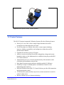
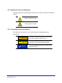
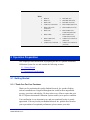
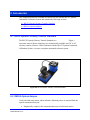
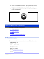
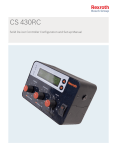
Radian Research, Inc. About This Manual Radian Research, Inc. makes no warranty on the accuracy of the information contained in this manual and accepts no liability for its use. The information contained in this manual remains the property of Radian Research, Inc. It is provided in good faith for the operation and servicing of this Radian Research, Inc. product. We reserve the right to take legal action where this information is divulged to third parties without our written consent or in circumstances that may cause us commercial harm. The operation of this equipment requires training and experience in electric meter testing. The information in this manual is designed to supplement existing knowledge and experience already attained and practiced by journeyman-level meter test technicians. Beginning meter test technicians should not attempt to operate this equipment without first gaining the basic knowledge of meter testing and the application of meter testing equipment from a certified training course. Copyright © 2012 Radian Research, Inc. Radian Research reserves the right to change any information in this document without notice . Table of Contents 1 Product Introduction and Specifications............................................................................ 7 1.1 Product Overview ............................................................................................................ 7 1.2 Product Features ............................................................................................................. 9 1.3 System Configurations....................................................................................................10 1.3.1 New System Configurations ...................................................................................................... 10 1.3.2 Upgrade Configurations ............................................................................................................. 10 1.3.3 Accessories ................................................................................................................................ 11 1.4 Safety Information ..........................................................................................................12 1.4.1 General Safety Summary .......................................................................................................... 12 1.4.2 Symbols Found on the Equipment ............................................................................................ 13 1.4.3 Conventions Used in this Manual ............................................................................................. 13 1.5 Specifications .................................................................................................................14 2 Operation Preparation ........................................................................................................17 2.1 Getting Started ...............................................................................................................17 2.1.1 Thank You For Your Purchase ................................................................................................. 17 2.1.2 Preparing Equipment for Use .................................................................................................... 18 2.1.3 System Setup and Training ....................................................................................................... 19 2.1.4 Registering Your Equipment ..................................................................................................... 20 2.2 Operational Considerations ............................................................................................21 3 System Components and Features....................................................................................22 3.1 RS-711 Syntron Signal Source .......................................................................................22 3.2 RS-932 Current Amplifier Module ...................................................................................23 3.3 Voltage/Current Amplifier Panel ......................................................................................23 3.4 RS-710 System Power Supply ........................................................................................23 3.5 RS-940 Data Collection Module ......................................................................................24 3.6 Potential and Current Indicator Panel .............................................................................25 3.7 System Cooling Module ..................................................................................................26 4 RS-933 Control Software ....................................................................................................26 4.1 Software Overview .........................................................................................................27 4.2 Software Documentation ................................................................................................27 4.3 System Requirements ....................................................................................................28 4.4 Setting Up the Equipment ...............................................................................................28 4.5 Installing the Software ....................................................................................................28 4.6 Menu Structure ...............................................................................................................30 4.6.1 Ribbon Tabs .............................................................................................................................. 31 4.6.1.1 System ................................................................................................................................... 31 4.6.1.2 Define Channels ..................................................................................................................... 31 4.6.1.3 Test ........................................................................................................................................ 31 4.6.1.4 Tools....................................................................................................................................... 37 4.6.2 Quick Access Toolbar ............................................................................................................... 40 4.7 Configuring the Software ....................................................................................................40 4.7.1 Operator .................................................................................................................................... 40 4.7.2 Test Configuration Setting......................................................................................................... 41 4.7.3 System Connection ................................................................................................................... 41 4.7.4 Database ................................................................................................................................... 42 4.7.5 Folders ...................................................................................................................................... 42 4.7.6 Auto Null .................................................................................................................................... 42 5 Applications Information ....................................................................................................44 5.1 Setting Up the Hardware ................................................................................................44 5.1.1 Hardware Requirements ........................................................................................................... 44 5.1.2 Hardware Setup ........................................................................................................................ 44 5.2 Setting Up the Software and Running the Test ...............................................................46 5.2.1 Start the Software ..................................................................................................................... 46 5.2.2 Associate DUTs to Channels .................................................................................................... 47 5.2.3 Open and Run the Test ............................................................................................................. 48 5.2.4 Viewing Results ......................................................................................................................... 50 5.2.5 Exporting Data .......................................................................................................................... 52 6 Accessories .........................................................................................................................53 6.1 RD-22 Dytronic Primary Transfer Standard ....................................................................53 6.2 RM-OA Optical Adapter ..................................................................................................53 7 Routine Maintenance and Service .....................................................................................54 7.1 Contact Information ........................................................................................................54 7.2 Routine Maintenance ......................................................................................................55 7.3 Service ...........................................................................................................................55 7.3.1 Service ...................................................................................................................................... 55 RS-933 Operations Manual 2-2013 RR 942011.E Radian Research, Inc. 4 7.3.2 Warranty Service ....................................................................................................................... 55 7.3.3 After-Warranty Service .............................................................................................................. 56 7.4 Helpful Documentation and Resources ...........................................................................57 Table of Figures Figure 1. RS-933 Syntron Automated Calibration System ........................................................................... 8 Figure 2. RD-22 Dytronic Primary Transfer Standard ................................................................................... 9 Figure 3. RS-933 Syntron Automated Calibration System Nameplate Containing Equipment Serial Number........................................................................................................................................................ 21 Figure 4. Front Panel of RS-940 Data Collection Module ........................................................................... 24 Figure 5. Main Power Switch on Potential and Current Indicator Panel. .................................................... 25 Figure 6. RS-933 Control Software Icon. .................................................................................................... 25 Figure 7. Ribbon Tabs and Quick Access Toolbar. .................................................................................... 30 Figure 8. Information Window ..................................................................................................................... 31 Figure 9. Configuration Window .................................................................................................................. 53 Figure 10. Define Channels Ribbon Tabs ................................................................................................... 53 Figure 11. Load Device File Window .......................................................................................................... 53 Figure 12. Test Ribbon Tabs....................................................................................................................... 53 Figure 13. Load Test File Window .............................................................................................................. 53 Figure 14. New Test Window ...................................................................................................................... 53 Figure 15. Legacy Data Review Window .................................................................................................... 53 Figure 16. Select Result Data Window ....................................................................................................... 53 Figure 17. Tools Ribbon Tabs ..................................................................................................................... 53 Figure 18. Stimulus State Window .............................................................................................................. 53 Figure 19. New Waveform Window ............................................................................................................ 53 Figure 20. Open Waveform File Window .................................................................................................... 53 Figure 21. Quick Access Toolbar ................................................................................................................ 40 Figure 22. Operator Information .................................................................................................................. 41 Figure 23. Test Configuration Information .................................................................................................. 41 Figure 24. System Connection Information................................................................................................. 42 Figure 25. Database Information ................................................................................................................ 42 Figure 26. Folders Information .................................................................................................................... 43 RS-933 Operations Manual 2-2013 RR 942011.E Radian Research, Inc. 5 Figure 27. Autonull ...................................................................................................................................... 44 Figure 28. Hardware Connections for Certifying an RD-2X Radian Research, Inc. Reference Standard . 46 Figure 29. RS-933 Control Software Icon ................................................................................................... 47 Figure 30. System Connected .................................................................................................................... 47 Figure 31. Select Channel Configuration .................................................................................................... 48 Figure 32. Select Refresh ........................................................................................................................... 48 Figure 33. Select Load Test ........................................................................................................................ 49 Figure 34. Select the Test File .................................................................................................................... 49 Figure 35. Test Screen................................................................................................................................ 51 Figure 36. Select Test/Select Result Data .................................................................................................. 51 Figure 37. Select the Test Results .............................................................................................................. 52 Figure 38. Test Results ............................................................................................................................... 52 Figure 39. Exporting Test Results ............................................................................................................... 53 Figure 40. RD-22 Dytronic Primary Transfer Standard ............................................................................... 54 Figure 41. RM-OA Optical Adapter ............................................................................................................. 54 RS-933 Operations Manual 2-2013 RR 942011.E Radian Research, Inc. 6 1 Product Introduction and Specifications This chapter provides an introduction to the RS-933 Syntron Automated Calibration System and contains the following sections: 1.1 Overview 1.2 Product Features 1.3 System Configurations 1.4 Safety Information 1.5 Specifications 1.1 Product Overview The Radian Research, Inc. RS-933 Syntron Automated Calibration System (see Figure 1) is designed for calibrating wide variety of test equipment. It provides the accuracy and diverse functionality needed by today’s metrology laboratories. The RS-933 offers: Optimum testing efficiency and increased productivity Simple operation Testing standardization that allows unsurpassed accuracy and linearity across the entire operating range Expansive testing capabilities, including: o Energy reference standards o Digital multimeters o Phase meters o Energy meters o Power meters o Revenue meters o Amp meters o Panel meters o Power quality meters RS-933 Operations Manual 2-2013 RR 942011.E Radian Research, Inc. 7 Figure 1. RS-933 Syntron Automated Calibration System RD-22 Dytronic Primary Transfer Standard When combined with the RD-22 Dytronic Primary Transfer Standard (see Figure 2), the RS-933 Syntron Automated Calibration System becomes a complete automated reference system. In this setup, a computer with the RD-22 is directly connected to the RS-940 Data Collection Module, and the Control Software receives processed measurement information from the standard. The pulse outputs of the portable standards are also connected to the RS-940 Data Collection Module. When the test is complete, the RS-933 Control Software displays test results in percent error or percent registration comparing the RD-22 to the unit being tested as well as comparing the RS-933 to the RD-22. In this manner, the RS-933 and RD-22 together effectively serve as a check and balance to the proper functioning of the test sequence. In addition, primary references of DC voltage, resistance, and time can be tested against the RD-22. This is a useful feature for laboratories that desire to perform a DC to AC transfer. RS-933 Operations Manual 2-2013 RR 942011.E Radian Research, Inc. 8 Figure 2. RD-22 Dytronic Primary Transfer Standard 1.2 Product Features The RS-933 Syntron Automated Calibration System offers the following features: Delivery of 1 mA–200 A from a single output eliminates the need to reconfigure test leads and reduces test time For all test points over 200mA, direct drive current output technology improves stability, repeatability, and settling time without the need for measurement feedback Guaranteed watt-hour accuracy of 50 ppm Ability to create user-defined waveforms; independent voltage and current harmonics relative to the fundamental are established using the provided RS933 Control Software Automatically tests up to 16 meters simultaneously with automatic results calculation and automated saving of data More than 60 measurement parameters including multiple VAR-hours Flexibility of single or multiple phases with harmonic control of each independent phase and axis Microsoft Windows-based RS-933 Control Software provides full automation and documentation control TCP/IP interface protocol allows any local or remote terminal to be used for control or data access Based on Radian’s proven Syntron technology RS-933 Operations Manual 2-2013 RR 942011.E Radian Research, Inc. 9 Creates a complete automated AC reference test system when combined with the Radian RD-22 Dytronic Primary Transfer Standard Two-year warranty Purchase includes 1–2 day on-site training and setup assistance by Radian Research, Inc. 1.3 System Configurations 1.3.1 New System Configurations The RS-933 Syntron Automated Calibration System is available in the following configurations: Model Number Features 931/8C/120A Single phase, 8 channel data collection, 120 A 933/8C/120A Three phase, 8 channel data collection, 120 A 931/8C/200A Single phase, 8 channel data collection, 200 A 933/8C/200A Three phase, 8 channel data collection, 200 A 931/16C/120A Single phase, 16 channel data collection, 120 A 933/16C/120A Three phase, 16 channel data collection, 120 A 931/16C/200A Single phase, 16 channel data collection, 200 A 933/16C/200A Three phase, 16 channel data collection, 200 A 1.3.2 Upgrade Configurations The Syntron Automated Calibration System can be upgraded as shown below. Contact your Radian Research, Inc. representative for additional information. RS-933 Operations Manual 2-2013 RR 942011.E Radian Research, Inc. 10 Data Collection Upgrade Only* Model Number Features UPG93X/16C DATA 16 channel data collection module *Requires return to factory and new computer platform RS-600 System Upgrade* Model Number Features 600UPG/931/16C/120 Single phase, 16 channel data collection,120 A 600UPG/931/16C/200 Single phase, 16 channel data collection, 200 A 600UPG/933/16C/120 Three phase, 16 channel data collection,120 A 600UPG/933/16C/200 Three phase, 16 channel data collection, 200 A *Requires return to factory and new computer platform RS-703A Single Phase System Upgrade Model Number Features 703/1P/UPG/931/16C/120 Single phase, 16 channel data collection,120 A 703/1P/UPG/931/16C/200 Single phase, 16 channel data collection, 200 A 703/1P/UPG/933/16C/120 Three phase, 16 channel data collection,120 A 703/1P/UPG/933/16C/200 Three phase, 16 channel data collection, 200 A *Requires return to factory and new computer platform RS-703A Three Phase System Upgrade* Model Number Features 703/3P/UPG/933/16C/120 Three phase, 16 channel data collection,120 A 703/3P/UPG/933/16C/200 Three phase, 16 channel data collection, 200 A *Requires return to factory and new computer platform 1.3.3 Accessories See Section 6 of this manual for accessories for the RS-933 Power and Energy Calibration System. RS-933 Operations Manual 2-2013 RR 942011.E Radian Research, Inc. 11 1.4 Safety Information Review the information in this section to avoid injury and prevent equipment damage. 1.4.1 General Safety Summary ! WARNING The operation of this equipment requires training and experience in electric meter testing. The information in this manual is designed to supplement existing knowledge and experience already attained and practiced by qualified electric utility personnel. The information in this manual is not intended to replace existing electric utility safety procedures and those listed in the Handbook for Electricity Metering. Operation of this equipment involves high voltage. Always wear the appropriate personal protective equipment and follow all safety precautions specified for high voltage activities. Follow proper grounding techniques when using this equipment. Follow all safety guidelines contained in this manual. ! CAUTION Do not use this equipment for any purpose other than for which it was designed. Do not operate the equipment outside of the environmental conditions specified in this manual, including areas that are wet or damp or where flammable gases or fumes are present. Do not operate this equipment with covers or panels removed. Keep equipment surfaces clean and dry. Handle the RS-933 Syntron Automated Calibration System components with care; it is a precision instrument. Inspect the equipment before each use. Do not use the equipment if damage is observed. Use only the specified fuses. Do not attempt to service this equipment; contact Radian Research, Inc. for service or repairs. RS-933 Operations Manual 2-2013 RR 942011.E Radian Research, Inc. 12 1.4.2 Symbols Found on the Equipment The following safety symbols appear on the RS-933 Syntron Automated Calibration System: Danger of electrical shock. Warning: Refer to manual. 1.4.3 Conventions Used in this Manual The following conventions are used in this manual to highlight important information: ! WARNING Indicates an imminently hazardous situation that can result in death or a serious injury. ! CAUTION Indicates a potentially hazardous situation that can result in an injury or equipment damage. NOTE Indicates important information you should review before proceeding. RS-933 Operations Manual 2-2013 RR 942011.E Radian Research, Inc. 13 1.5 Specifications Operational Test voltage 60–630 VAC at 60 Hz 60–525 VAC at 50 Hz [(10.5)*(F) not to exceed 630 VAC] (0.001 volt increments) (V < 60 VAC is at linearly derated accuracy) VAout = 150 VA/phase at 120VAC or higher Test current 1 mA to 200 A AC in 1mA increments Test frequency 47–63 Hz (fundamental) Test phase angle 0–360º in 0.00001º increments Stability Included within system accuracy specification Recalibration interval 365 days Warm-up time 30 minutes Watthours Accuracy ± 0.005% ± traceability to NIST with fundamental waveforms This accuracy specification is listed as Percent of Reading and applies across the entire voltage and current operating range. Is also includes the variables of stability for one year after calibration, power factor, and test system errors. Influences affecting accuracy Temperature: +0.00006% typical, +0.0002% maximum/°C from 22 °C 21–25 °C (70–77 °F) for specified accuracy Pulse input BNC; up to 16 channels Pull-up resistor value of 150, 1K, 10K, 100K Ohms (programmable) I/O Port RJ45 jack; up to 16 channels Physical Size Height: 63 in (1.6 m) Width: 47 in (1.2 m) Length: 25.5 in (0.7 m) Maximum Weight 957 lbs (434 kg) Warranty 2-year warranty against defects in material or workmanship; extended warranties are available RS-933 Operations Manual 2-2013 RR 942011.E Radian Research, Inc. 14 Electrical Power requirements 240 VAC, 40 A Supply frequency 48–62 Hz Fuses RS-711 Syntron Signal Source: Littelfuse KLKD004 Littelfuse 0312.125 RS-710 System Power Supply: Littelfuse 0314015.HXP (15 A 250 V ceramic) Littelfuse 0312.250HXP (.25 A 250 V fast acting) Environmental Operating temperature 21–25 °C (70–77 °F) for specified accuracy Storage temperature 0º to 50 ºC (32º to 122 ºF) Relative humidity 15–80% Shock and vibration Any that is nondestructive Water resistance Neither splash proof nor water resistant Traceability Calibration compliance ISO 9001:2000 and ANSI/NCSL Z540-1 using applicable Radian Research, Inc. procedures Test conditions Temperature: 23 (+/-2) ºC Relative humidity: 15–80% Reference to watthours Calibrated to a bank of 3 RD-22-RTS Dytronic Primary Watthour Standards that are directly traceable to NIST, or by accuracies derived from the accepted values of natural physical constants, or by accuracies derived from accepted ratio type calibration techniques. Calibration is then confirmed across all ranges with RD-22-RTS Dytronic Transfer Standards. Reference to frequency Calibrated using a Hewlett Packard 100 MHz Universal Counter calibrated using the Arbiter Systems Model 1083B GPS Satellite-Controlled Frequency Standard. The frequency reference for the RS-933 is loaded within the RS-940. Reference to volts Calibrated to a bank of 3RD-22-RTS Dytronic Transfer Standards that is traceable to NIST. Note: All references supporting this calibration system are calibrated on a schedule that is adjusted to maintain traceability at the required accuracy level. RS-933 Operations Manual 2-2013 RR 942011.E Radian Research, Inc. 15 Testing Capability Reference standards Up to 8 SC-10 standards Up to 4 IB-10 standards Up to 16 Radian Research, Inc. standards Watthour meters Up to 4 induction meters (typical) Up to 4 solid state meters (typical) Instruments Analog or digital AC voltmeter Analog or digital AC ammeter Wattmeter Phase angle meter Voltage chart recorder Current chart recorder Measurement functions Accumulated Wh (net) Wh (delivered) Wh (received) VARh (net) VARh (delivered) VARh (received) VARh INT (net) VARh INT (delivered) VARh INT (received) VARh INT 50 VARh INT 60 Qh VAh RMS VAh AVE Vh RMS Vh AVG Ah RMS Ah AVE V2h A2h Instantaneous RS-933 Operations Manual 2-2013 RR 942011.E Radian Research, Inc. W VAR VAR INT VAR INT 50 VAR INT 60 VAR RMS VA RMS VA AVE V RMS V AVE dV RMS dV AVE A RMS A AVE Phase Phase OVR Phase RMS Phase AVG PF PF OVR PF RMS PF AVE dPhase Freq Time 16 Delta Delta Wh (net) Delta Wh (delivered) Delta Wh (received) Delta VARh (delivered) Delta VARh (received) Delta W Delta VA Delta VAR VAR Cross Connected Delta VAR Cross Connected Delta VAh Delta VARh Delta VARh Cross Connected VARh Cross Connected Delta VARh Cross Connected (delivered) Delta VARh Cross Connected (received) VARh Cross Connected (delivered) VARh Cross Connected (received) 2 Operation Preparation This chapter provides information on preparing the RS-933 Syntron Automated Calibration System for use and contains the following sections: 2.1 Getting Started 2.2 Operational Considerations 2.1 Getting Started 2.1.1 Thank You For Your Purchase Thank you for purchasing this quality Radian Research, Inc. product. Radian reference standards are recognized throughout the world for their unparalleled accuracy, precision, and stability. We have taken every effort to ensure that your RS-933 Syntron Automated Calibration System reaches you in perfect condition. Your satisfaction is very important to us, and your continued loyalty is greatly appreciated. If for any reason your Radian Research, Inc. product does not meet your expectations of exceptional performance, please contact your sales RS-933 Operations Manual 2-2013 RR 942011.E Radian Research, Inc. 17 representative or Radian Research, Inc. Radian Research, Inc. 3852 Fortune Drive Lafayette, IN 47905 USA Tel: (765) 449-5500 Fax: (765) 448-4614 Email: [email protected] Website: www.radianresearch.com 2.1.2 Preparing Equipment for Use Follow these steps to prepare your RS-933 Syntron Automated Calibration System for use. 1. Unpack and inspect: Carefully remove the equipment from the packaging, and check for any signs of damage. NOTE If you observe any damage to the equipment, immediately notify the carrier and your sales representative. 2. Verify the contents: Verify that your shipment includes the following items: o Tower assembly: Double-wide cabinet RS-940 Data Collection Module RS-711 Syntron Signal Source (1 or 3, depending on model number) RS-710 System Power Supply (2) RS-932 Current Amplifier Modules (1 or 3, depending on model number) RS-935 Potential/current connection panel RS-936 Potential and current indicator panel RS-937 System cooling module (2) RS-933 Operations Manual 2-2013 RR 942011.E Radian Research, Inc. 18 Power lock switch key (4) o Cables and cords: Control computer interface cable Un-terminated system power cord External potential cable set (1 or 3, depending on model number) External current cable set (1 or 3, depending on model number) RM-1C 6' BNC cables (8 or 16, depending on model number) Ethernet communication cables (9 or 17, depending on model number) Syntron Cable Adaptor Kit o RS-933A tool kit, containing a 1/8” ball head Allen driver, bent-tip pliers, and a 12 mm hex L-key o Calibration report(s) o RS-933 Control Software o Optional accessories NOTE If any items are missing from your shipment, contact Radian Research, Inc. 2.1.3 System Setup and Training The purchase of the RS-933 Syntron Automated Calibration System includes onsite setup and training assistance by Radian Research, Inc. Contact Radian Research, Inc. to coordinate the site visit. Prior to the site visit: Determine a suitable location for the equipment. Provide a suitable power source for the system. See Section 2.2 in this manual for details on placement, cooling, and power. ! CAUTION RS-933 Operations Manual 2-2013 RR 942011.E Radian Research, Inc. Do not attempt to set up the RS-933 without a Radian Research, Inc. representative present. 19 2.1.4 Registering Your Equipment Register your equipment to: Activate the equipment warranty. Receive firmware and software updates as well as product application notes from Radian Research, Inc. NOTE You must register your equipment at www.radianresearch.com/reg to activate the twoyear equipment warranty. If you do not activate the warranty, the warranty period is reduced to one year. Follow these steps to register your RS-933 Syntron Automated Calibration System: 1. Navigate to www.radianresearch.com/reg. 2. Complete the online form. The serial number can be found on the top left corner on the rear of the unit (see Figure 3). RS-933 Operations Manual 2-2013 RR 942011.E Radian Research, Inc. 20 Figure 3. RS-933 Nameplate Containing Equipment Serial Number 2.2 Operational Considerations To protect the RS-933 Syntron Automated Calibration System and ensure optimal performance, follow these guidelines: Placement: The RS-933 is designed for use in a dry, clean, temperaturecontrolled environment that is free from dust, debris, and flammable gases and fumes, such as a standards lab. The system should be placed in an area where space is available for the system control computer, the devices under test, and any accessories. Operating this equipment in an unsuitable environment can affect equipment performance and shorten equipment life. Cooling: When placing the RS-933 for use, do not block the Cooling System Module on the lower front of the unit. NOTE NOTE Ensure 6" of space exists between the front and rear of the unit and any wall or structure to allow adequate air flow to and from the cooling system. Power: The RS-933 requires 240 VAC, 40 A service. RS-933 Operations Manual 2-2013 RR 942011.E Radian Research, Inc. 21 3 System Components and Features This chapter provides detailed information on the system components of the RS-933 Syntron Automated Calibration System and their features. It contains the following sections: 3.1 RS-711 Syntron Signal Source 3.2 RS-932 Current Amplifier Module 3.3 Voltage/Current Amplifier Panel 3.4 RS-710 System Power Supply 3.5 RS-940 Data Collection Module 3.6 Potential and Current Indicator Panel 3.7 System Cooling Module NOTE All components of the RS-933 include a power indicator light on the front panel. The indicator light is lit when power is present at that component. 3.1 RS-711 Syntron Signal Source The RS-711 Syntron Signal Source generates voltage and current signals with extreme accuracy and extremely low distortion. It has the following features: Accuracy of 0.0003 Hz; eliminates error of calibration on frequency-sensitive devices Test frequency of 48–63 Hz Test phase angle of 0–360° in 0.000001° increments Allows for true three-phase testing with 123/321 phase rotation as specified by the operator Can also be used for single-phase testing RS-933 Operations Manual 2-2013 RR 942011.E Radian Research, Inc. 22 Synthesis and generation of arbitrary waveforms (first through sixty fourth harmonic) as specified by the operator via the RS-933 Control Software (useful for evaluation testing of electro-mechanical and solid-state meter designs) 3.2 RS-932 Current Amplifier Module The gain error and the distortion of the RS-932 Current Amplifier Module is extremely small in proportion to the 50 ppm specification of the RS-933 Syntron Automated Calibration System. The current amplifier module has the following features: Can source any current from 1 mA–200 A in 1 mA increments Extremely low output impedance, which minimizes burden errors Output power is 50 VA per phase at 50 A, which is sufficient for testing multiple reference standards 3.3 RS-935 Voltage/Current Amplifier Panel The RS-935 Voltage/Current Amplifier Panel provides the external potential and current connection interfaces. 3.4 RS-710 System Power Supply The RS-710 System Power Supply provides power to all components of the RS-933 Syntron Automated Calibration System. It provides high accuracy by: Coupling in the incoming power and removing the common ground between components of the RS-933, which makes it possible to send highly accurate signals to the components. Operating at 1 kHz, making individual power supplies more compact and easily shielded. RS-933 Operations Manual 2-2013 RR 942011.E Radian Research, Inc. 23 3.5 RS-940 Data Collection Module The RS-940 Data Collection Module interfaces to the pulse outputs of the standards under test and transfers the data to the system computer. Figure 4 shows the front panel of the RS-940. It has the following features: Connects directly to a personal computer for direct memory access, which permits rapid data collection from a large number of standards using the RS933 Control Software Interfaces directly to the Radian Research, Inc. RM-1H optical pickup, which is used to sense the calibration LED on solid state meters Interfaces with the RM-DS Meter Disk Sensor, which is used to sense disk rotation when testing induction meters Available with 8 or 16 channels Serial interface connections Figure 4. Front Panel of RS-940 Data Collection Module (16 channel version 8 channel not shown) RS-933 Operations Manual 2-2013 RR 942011.E Radian Research, Inc. 24 3.6 RS-936 Potential and Current Indicator Panel The RS-936 Potential and Current Indicator Panel indicates the potential and current phases that are active during testing. It also contains the main power switch for the RS-933 Syntron Automated Calibration System (see Figure 5). In the off position, this switch can be locked into place with a padlock or a lockout-tagout mechanism. Figure 5. RS-933 Main Power Switch on Potential and Current Indicator Panel. RS-933 Operations Manual 2-2013 RR 942011.E Radian Research, Inc. 25 3.7 RS-937 System Cooling Module The RS-933 Syntron Automated Calibration System includes two RS-937 System Cooling Modules located at the bottom of each tower. Each cooling module includes the following features: Three 24 V brushless DC fans that each produce over airflow of over 150 cfm Acoustical insulation to minimize noise A replaceable 10" x 16" x 1" air filter to reduce dust inside the unit (available from Radian Research, Inc.) NOTE Ensure 6" of space exists between the front and rear of the unit and any wall or structure to allow adequate air flow to and from the cooling system. 4 RS-933 Control Software This chapter describes the RS-933 Control Software and contains the following sections: 4.1 Software Overview 4.2 Software Documentation 4.3 System Requirements 4.4 Setting Up the Equipment 4.5 Installing the Software 4.6 Configuring the Hardware 4.7 Menu Structure 4.8 Configuring the Software RS-933 Operations Manual 2-2013 RR 942011.E Radian Research, Inc. 26 4.1 Software Overview RS-933 Control Software is used to: Operate the RS-933 Syntron Automated Calibration System Develop test sequences for many types of equipment, including electrical energy reference standards, electro-mechanical and solid-state watthour meters, voltmeters, and ammeters Generate arbitrary waveforms Store, print, and export test data NOTE A personal computer is required to operate the RS933 Control Software. This computer is not included in the purchase of the RS-933. 4.2 Software Documentation This manual section is intended to provide a brief overview of the control software, including an example test set-up. See Section 5 of this manual for instruction for certifying a Radian Research, Inc. RD-2X series reference standard using the RS-933 Syntron Automated Calibration System. Additional application notes, on testing a wide range of devices, can be found at Radian Research’s website: www.radianresearch.com. Contact Radian Research, Inc. at (765) 449-5500 for additional support. RS-933 Operations Manual 2-2013 RR 942011.E Radian Research, Inc. 27 4.3 System Requirements RS-933 Control Software can be run only on Microsoft Windows. The minimum system requirements are listed below. Additional disk space required, depending on amount of test results saved. Component Minimum Requirement Computer and processor 1 GHz processor Memory 1GB RAM (32-bit) or 2 GB RAM (64-bit) Hard disk 16 GB (32-bit) or 20 GB (64-bit) Display DirectX 9 graphics device with WDDM 1.0 or higher driver Operating system Windows 7 32-bit or 64-bit Additional requirements Secondary LAN interface 4.4 Setting Up the RS-933 For all new system purchases, a Radian Research, Inc. representative will set up the RS-933 Syntron Automated Calibration System and install the RS-933 Control Software during the site visit. See Section 2.1.3 of this manual. 4.5 Installing the Software Follow these steps to install the software: 1. Insert the disk into the computer’s drive. 2. Locate file setup.exe, click and then follow the instructions on the screen. When the installation is complete, the icon below (see Figure 5) will appear on the desktop. RS-933 Operations Manual 2-2013 RR 942011.E Radian Research, Inc. 28 Figure 6. RS-933 Control Software Icon 3. Double-click the icon to start the software. NOTE During installation, the RS-933 Control Software will create a group of directories where device configurations, test setups, waveforms, and test results are stored. 4. Download and run the setup program for “Microsoft SQL Server 2012 Express with Tools” from Microsoft’s website. Select “New SQL Server stand-alone installation or add features to an existing installation”. Accept license agreement, click Next. Ensure selected features and installation directory are set to default, click Next. Ensure instance configuration settings are set to defaults, click Next. Ensure server configuration settings are set to defaults, click Next. At database engine configuration: a. Select “Mixed Mode” under Authentication Mode. b. Enter a password for the administrator c. Click Next. Click Next for Error Reporting. Allow installation to run – this may take a few minutes. Click Close – installation is finished. Close the setup program. Launch SQL Server Management Studio. Login using Windows Authentication as administrator File | Open | File Open “Generate933Database.sql”. Modify the path to “RadianRS933.mdf” and “RadianRS933_log.ldf” to the correct path for your installations. Click “Execute Query” and ensure that the query executes successfully. RS-933 Operations Manual 2-2013 RR 942011.E Radian Research, Inc. 29 Close SQL Server Management Studio 5. Configure the software by following the instructions in Section 4.7 of this manual. 4.6 Menu Structure The RS-933 Control Software includes a series of ribbon tabs and associated buttons. A quick access toolbar is also included, which contains many of the most used functions (see Figure 6). Both are described below. The Quick Access Toolbar contains many of the most frequently used functions. Ribbon Tabs contain all configuration and testing functions. Figure 7. Ribbon Tabs and Quick Access Toolbar RS-933 Operations Manual 2-2013 RR 942011.E Radian Research, Inc. 30 4.6.1 Ribbon Tabs The RS-933 Control Software ribbon tabs and the associated buttons allow easy access to all configuration and testing functions. Each ribbon tab is described below. 4.6.1.1 System Contains important system information such as module serial numbers, calibration dates, number of I/O channels, database connection, software version, and an error log (see Figure 7). Information Figure8. Information Window RS-933 Operations Manual 2-2013 RR 942011.E Radian Research, Inc. 31 Allows the user to configure various system parameters such as operator identification, comments, test settings, and the system IP address. This window also allows the user to select the location of saved database, test, waveform, device, and results files. An autonull can also be executed. Configuration Figure9. Configuration Window RS-933 Operations Manual 2-2013 RR 942011.E Radian Research, Inc. 32 4.6.1.2 Define Channels Figure 10. Define Channels Ribbon Tabs Channel Configuration Allows the user to associate and configure the devices under test (DUT’s) to the available RS940 Data Collection Module channels (see Figure 10). Figure10. Channel Configuration Window Refresh – Scans all the available channels and populates the channel table based on the connected DUT’s Add Device – Allows the customer to add a device to the channel table Disconnect All – Removes all channel configurations Device: Model – The DUT’s model number Serial Number – The DUT’s serial number Name – This field will auto-populate, if the DUT is an RD standard and has a name programmed (see the RD standard’s Operations Manual for details) Enabled – Enables/disables the entire DUT Connections: Comm Port – Establishes the specific RS-940 serial communications input channel for the DUT RS-933 Operations Manual 2-2013 RR 942011.E Radian Research, Inc. 33 Pulse Ports – Establishes the specific RS-940 pulse input channel(s) for the DUT. Measurements: Enabled – Enables/disables a single phase of the DUT Name – Defaults to the device name, if programmed. If not programmed, it will set to the DUT’s serial number. If no serial number is available, the model number is displayed. I-Turns – Establishes the scaling factor for the number of turns around the input CT of the DUT. Stimulus Seen – Allows the user of a single potential/current phase or combination of potential/current phases to apply stimuli to the DUT, enter the voltage, current, phase angle, and waveform into the appropriate phases and check Stimulus On. Opens a Select Device File window (see Figure 11) for browsing to a pre-configured device file (see Figure 11). Load Device Figure 11. Load Device File Window RS-933 Operations Manual 2-2013 RR 942011.E Radian Research, Inc. 34 4.6.1.3 Test Figure 12. Test Ribbon Tabs Opens a Select Test File window for browsing to a pre-configured test file. Load Test Figure13. Load Test File Window New Test RS-933 Operations Manual 2-2013 RR 942011.E Radian Research, Inc. Allows the user to create a new test sheet. 35 Figure 14. New Test Window Allows retrieval and review of archived RS-703 System Test Results Legacy Data Review Figure 15. Legacy Data Review Window Select Result Data RS-933 Operations Manual 2-2013 RR 942011.E Radian Research, Inc. Allows the user to review saved test results. 36 Figure 16. Select Result Data Window 4.6.1.4 Tools Figure 17. Tools Ribbon Tabs Stimulus State RS-933 Operations Manual 2-2013 RR 942011.E Radian Research, Inc. Allows the user to set and apply specific potential, current, phase, frequency, and harmonic stimuli to the DUT’s 37 Figure 18. Stimulus State Window Allows the user to create new potential and current waveforms, with various harmonic content. New Waveform Figure19. New Waveform Window Name – The name of the waveform file Description – Description of the waveform Active – Allows the user to activate and deactivate each of the 64 harmonics indescriminately RS-933 Operations Manual 2-2013 RR 942011.E Radian Research, Inc. 38 Amplitude – The strength of the harmonic component, as referenced to the fundamental Phase – The phase of the harmonic component, as referenced to the fundamental Controls: Normalize To Unity RMS – Normalizes the harmonic values so that the waveform’s total RMS is one. Normalize To Fundamental – Scales the harmonic values to a fundamental amplitude of one. THD – The total calculated THD for all the harmonic content and the fundamental Phase Units – Degrees or Radians Waveform File: Revert to Saved Data – Clears all changes and restores original waveform Save Waveform – Saves the waveform changes to the original file Save Waveform As – Saves the waveform changes to a new file Opens a Select Harmonic Waveform File window for browsing to a pre-configured waveform file. Open Waveform Figure20. Open Waveform File Window RS-933 Operations Manual 2-2013 RR 942011.E Radian Research, Inc. 39 4.6.2 Quick Access Toolbar The RS-933 Control Software Quick Access Toolbar allow easy access to the most frequently used configuration and testing functions. Figure 21. Quick Access Toolbar 4.7 Configuring the Software The System/Configuration screen allows the user to configure various system parameters such as operator identification, comments, test settings, and the system IP address. This window also allows the user to select the location of saved database, test, waveform, device, and results files. An autonull can also be executed. 4.7.1 Operator Use the Operator section fields to specify: The operator ID information Operator comments and notes Figure 22. Operator Information RS-933 Operations Manual 2-2013 RR 942011.E Radian Research, Inc. 40 4.7.2 Test Configuration Settings Use the Test Configuration section fields tab to specify: Default Display View - % Error, %Registration, PPM, Measured, Expected, Nulling PPM, or Correction Factor % Error: The percent error of a DUT is the difference between its percent registration and one hundred percent. % Registration: The percent registration of a DUT is the ratio of the actual registration of the meter to the true value of the quantity measured in a given time, expressed as a percent. PPM: The % Error expressed in parts per million (e.g. 0.001% error = 10ppm) Measured: The value of the stimuli measured by the DUT Expected: The expected reading, based on the selected waveform, voltage and current settings, and phase inputs Nulling PPM: % Registration expressed in PPM Correction Factor: The amount, normalized to one, to correct errors in the DUT. Default Point Order – By Row, By Column (down/up), or By Column (down) Phase Offset Model – Phase 1:2-2:3, or Phase 1:2-1:3 Figure 23. Test Configuration Information 4.7.3 System Connection Use the System Connection section fields to specify: RS-940 System IP Address NOTE RS-933 Operations Manual 2-2013 RR 942011.E Radian Research, Inc. Each RS-940 has its own IP address. This address is typically determined at the time of purchase. If you do not know the system’s address, please contact Radian Research, Inc. for further assistance. 41 Connect/Disconnect to the system Autoconnect to last RS-940 System Figure 24. System Connection Information 4.7.4 Database Use the Database section fields to: Source Path User Name Password Test Connection Figure 25. Database Information 4.7.5 Folders Use the Folders section fields to: Select the location of Test files Select the location of Waveform files Select the location of Device files Select the location of Results files RS-933 Operations Manual 2-2013 RR 942011.E Radian Research, Inc. 42 Figure 26. Folders Information 4.7.6 AutoNull Use the AutoNull section to: Execute a AutoNull NOTE Auto Null: Eliminates any DC component in the potential and current output signals. Figure 27. Autonull RS-933 Operations Manual 2-2013 RR 942011.E Radian Research, Inc. 43 5 Applications Information This chapter explains how to certify a Radian Research, Inc. RD-2X series reference standard using the RS-933 Syntron Automated Calibration System and contains the following sections: 5.1 Setting Up the Hardware 5.2 Setting Up the Software and Running the Test 5.3 Creating a New Test Device 5.4 Creating Voltages and Current Signals with Harmonic Content NOTE This section contains only instructions for certifying Radian Research, Inc. RD-2X series reference standards. Application notes on conducting instructions for additional tasks are available; see Section 7.4 in this manual. 5.1 Setting Up the Hardware 5.1.1 Hardware Requirements The following equipment is needed to certify a RD-2X reference standard with the RS-933 Syntron Automated Calibration System: 1. RD-2X reference standard (device under test) 2. 120 VAC auxiliary power input cable (Radian Research, Inc. part number 194015) 3. Test connection kit (Radian Research, Inc. part number 109321 supplied) 4. RJ-45 cable (Radian Research, Inc. part number 194200) 5.1.2 Hardware Setup Follow these steps to set up the hardware: 1. With the main power switch on the Potential and Current Indicator Panel in the off position, verify that: RS-933 Operations Manual 2-2013 RR 942011.E Radian Research, Inc. 44 The personal computer with the RS-933 Control Software is connected to the RS-933 and ready for use. The main power cable of the RS-933 is connected to the power source. 2. Turn on the main power to the RS-933 using the main power switch on the Potential and Current Indicator Panel. Make sure both RS-710 key switches are in the on position. 3. Turn on the personal computer with the RS-933 Control Software. 4. Connect the hardware as shown in Figure: Connect From Connect To Cable 120 VAC Auxiliary power input of the DUT 120 VAC auxiliary power input cable SERIAL PORT of the DUT Channel 1 of the RS-940 Data Collection Module (front panel) RJ-45 Cable Potential output of the Voltage/Current Amplifier Panel Potential input of the DUT External potential cable Current output of the Voltage/Current Amplifier Panel B current input of the DUT External current cable Right angle current adaptors (hardwired to RS933) Figure 28. Hardware Connections for Certifying an RD-2X Radian Research, Inc. Reference Standard 5. Configure the DUT as follows: RS-933 Operations Manual 2-2013 RR 942011.E Radian Research, Inc. 45 Component Setting Port 2 Wh Pulse constant 0.00001 Wh/pulse Port polarity + NOTE For optimum accuracy and stability, the recommended warm-up time for the RS-933 system is 30 minutes. NOTE Consult the user manual for the DUT for additional information on configuration. 5.2 Setting Up the Software and Running the Test 5.2.1 Start the Software Follow these steps to start the software: 1. Double-click the RS-933 Control Software icon on the personal computer desktop. Figure 29. RS-933 Control Software Icon NOTE Upon power-up, the RS-940 module executes a diagnostic routine. This routine can take a few minutes. If the control software is opened prior to the completion of this routine, the software will either deny the connection or display an initializing message. RS-933 Operations Manual 2-2013 RR 942011.E Radian Research, Inc. 46 The software will start. Browse to System/Configuration screen and ensure that the system is connected Figure 30. System Connected 5.2.2 Associate DUTs to Channels Follow these steps to associate the DUTs to the appropriate channels: 1. Select Define Channels/Channel Configuration Figure 31. Select Channel Configuration The Channel Configuration window will appear. Select Refresh The RS-940 will scan all the available channels for communications with connected Radian RD Reference Standards and automatically associate them to the connected channel. RS-933 Operations Manual 2-2013 RR 942011.E Radian Research, Inc. 47 Figure 32. Select Refresh Enter an appropriate DUT name (optional). Select the number of I-Turns and the appropriate phases for Stimulus Seen. a. I-Turns = 1.0000 b. Stimulus Seen = check Phase 1 only NOTE I-Turns: The number of current turns applied to the input of the DUT. 5.2.3 Open and Run the Test Follow these steps to open and run the test: 1. Select Test/Load Test. Figure 33. Select Load Test RS-933 Operations Manual 2-2013 RR 942011.E Radian Research, Inc. 48 2. Browse to and select Certify RD Standard Watthour 60Hz, and then click Open. Figure 34. Select the Test File The Test Run screen will appear. The serial numbers or names of the previously associated DUTs are shown on tabs on the right. The screen displays the test points. 3. If necessary, click any of the current, voltage, or phase (degrees) values in the Test Run screen to make changes. 4. Configure the test options listed at the bottom of the Test Run screen as follows: Setting Selection or Value Meas Mode WYE K Factor 0.000010 Frequency 60.000000 Stab Time User Preference (1 second increments; 1to 9,999seconds) Test Time User Preference (1 second increments; 1sec to 49.77days) RS-933 Operations Manual 2-2013 RR 942011.E Radian Research, Inc. 49 View User Preference Default View User Preference Source Comm (pulse, comm, or pulse/comm) Show Phase Check Phase 1 only Phase Offset 1:2 = 0.000000; 2:3 = 0.000000 Point Order User Preference Volt Wave All set to Pure Curr Wave All set to Pure 5. Select Run. The test will automatically start with the first test point and continue until all test points have been executed. Figure 35. Test Screen 5.2.4 Viewing Results Follow these steps to view results: 1. Select Test/Select Results Data. RS-933 Operations Manual 2-2013 RR 942011.E Radian Research, Inc. 50 Figure 36. Select Test/Select Result Data 2. From the list, select the required test by locating the serial number and time/date of the test. Figure 37. Select the Test Results The desired results data will appear. RS-933 Operations Manual 2-2013 RR 942011.E Radian Research, Inc. 51 Figure 38. Test Results 5.2.5 Exporting Data Data from the RS-933 Control Software can be exported easily by selecting the Export button from the Test/Select Result Data screen. This exports the data from the current test sheet or results within the database to an Excel compatible *.csv file. Figure 39. Exporting Test Results RS-933 Operations Manual 2-2013 RR 942011.E Radian Research, Inc. 52 6 Accessories This chapter describes the available accessories for use with the RS-933 Syntron Automated Calibration System and contains the following sections: 6.1 RD-22 Dytronic Primary Transfer Standard 6.4 RM-OA Optical Adapter 6.1 RD-22 Dytronic Primary Transfer Standard The RD-22 Dytronic Primary Transfer Standard (see Figure ) represents state-of-the-art technology in a commercially available true DC to AC accuracy transfer reference. When combined with the RS-933 Syntron Automated Calibration System, it creates a complete automated reference system. Figure 40. RD-22 Dytronic Primary Transfer Standard 6.2 RM-OA Optical Adapter Used with solid-state meters whose infrared calibration pulses are emitted from the optical communications port. Magnetically couples to the communications port of solid-state meters. RS-933 Operations Manual 2-2013 RR 942011.E Radian Research, Inc. 53 Suction cup of the Radian Research, Inc. RM-1H Infrared Optical Pickup attaches to the clear polycarbonate cover of the RM-OA. Incorporates a rare-earth permanent magnet for exceptional holding power over the life of the product. Figure 41. RM-OA Optical Adapter 7 Routine Maintenance and Service This chapter contains the following sections: 7.1 Contact Information 7.2 Routine Maintenance 7.3 Service 7.4 Helpful Documentation and Resources 7.1 Contact Information For questions related to maintenance and service, contact Radian Research, Inc.: Radian Research, Inc. 3852 Fortune Drive Lafayette, IN 47905 USA Tel: (765) 449-5500 Fax: (765) 448-4614 Email: [email protected] Website: www.radianresearch.com RS-933 Operations Manual 2-2013 RR 942011.E Radian Research, Inc. 54 7.2 Routine Maintenance The RS-933 Syntron Automated Calibration System requires the following routine maintenance: Frequency Activity Before each use Yearly Or as needed Ensure that the work area is clean and dry. Ensure that the system power connection is secure and in good condition. Ensure that the equipment is free from dust. Recalibrate and recertify the system. Replace the cooling fan filters (see Section 3.7 in this manual). 7.3 Service 7.3.1 Service The RS-933 Syntron Automated Calibration System is serviceable only by Radian Research, Inc. ! WARNING The RS-933 produces high voltages and is serviceable only by Radian Research, Inc. Attempts to service the equipment by unqualified personnel can result in personnel injury. 7.3.2 Warranty Service Radian Research, Inc. warrants that each product is free from defects in material and workmanship. Our obligation under this warranty is to repair or replace any instrument or component therein that, within two years after shipment and with normal use, proves to be defective upon examination. To Obtain Warranty Service All warranty returns must have a return materials authorization (RMA) number. To obtain an RMA, visit www.radianresearch.com/forms/RMA/RMA-form.html. Follow these guidelines to ensure prompt warranty service: RS-933 Operations Manual 2-2013 RR 942011.E Radian Research, Inc. 55 Radian Research, Inc. must authorize all warranty replacements. Ship returned items prepaid, fully insured, and in the original packing to minimize the possibility of damage. Radian Research, Inc. will not accept collect shipments and does not accept liability for damage caused by improper packing or handling during shipment. Include in the shipment a detailed description of the problem and the events that led up to the development of the problem. Radian Research, Inc. will pay local domestic surface freight costs to return the product to the customer. Radian will not pay for overnight or express shipping service. Use the following address for warranty returns: Radian Research, Inc. 3852 Fortune Drive Lafayette, IN 47905 USA Attn: Service 7.3.3 After-Warranty Service If after-warranty service by Radian Research, Inc. is needed: A purchase order is required. The owner must pay all shipping costs. If requested, Radian Research, Inc. can provide an estimate for the repair; however, if the repair is not made, the cost of labor required to obtain the estimate will be invoiced at the hourly repair rate. To Obtain After-Warranty Service All after-warranty service requests must have a return materials authorization (RMA) number. To obtain an RMA, visit www.radianresearch.com/forms/RMA/RMA-form.html. Payment information must also be provided (purchase order or credit card). Please follow these guidelines to ensure prompt after-warranty service: Ship returned items prepaid, fully insured, and in the original packing to minimize the possibility of damage. RS-933 Operations Manual 2-2013 RR 942011.E Radian Research, Inc. 56 Include in the shipment a detailed description of the problem and the events that led up to the development of the problem. Radian Research, Inc. will invoice return shipping costs to the customer. 7.4 Helpful Documentation and Resources http://www.radianresearch.com/products/RS-933.php http://www.radianresearch.com/brochures/RS-933.pdf RS-933 Operations Manual 2-2013 RR 942011.E Radian Research, Inc. 57